Introduction
This document describes how to integrate ISE with Prime Infrastructure to gain visibility for authenticated endpoints.
Prerequisites
Requirements
Cisco recommends that you have knowledge of these topics:
- Cisco ISE.
- Cisco Prime Infrastructure.
- Wireless or Wired AAA flow for endpoints authenticating against ISE.
- SNMP Configuration on NADs (Network Access Devices) like Switches and WLCs.
Components Used
The information in this document is based on these software and hardware versions:
- ISE 3.1 deployment.
- Cisco Prime Infrastructure 3.8.
- C6816-X-LE running Cisco IOS® 15.5.
- Windows 10 Machine.
The information in this document was created from the devices in a specific lab environment. All of the devices used in this document started with a cleared (default) configuration. If your network is live, ensure that you understand the potential impact of any command.
Configure
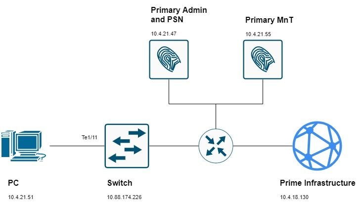
Network Diagram
Configurations
Switch Configuration
1. Configure the Network Access Device (NAD) for AAA authentication against ISE. In this guide you are using this configuration:
aaa new-model

radius server ise31
 address ipv4 10.4.21.47 auth-port 1812 acct-port 1813
 key Cisc0123

aaa server radius dynamic-author
 client 10.4.21.47 server-key Cisc0123

aaa group server radius ISE
 server name ise31

aaa authentication dot1x default group ISE
aaa authorization network default group ISE
aaa accounting dot1x default start-stop group ISE

dot1x system-auth-control
2. Configure Device Tracking in the switch:
device-tracking policy DT1
 tracking enable

device-tracking tracking auto-source
3. Configure the switchport for dot1x authentication and attach the device tracking policy to it:
interface TenGigabitEthernet1/11
 device-tracking attach-policy DT1
 authentication host-mode multi-domain
 authentication order dot1x mab webauth
 authentication priority dot1x mab webauth
 authentication port-control auto
 mab
 dot1x pae authenticator
4. Configure RO SNMP community and SNMP traps to meet your networks requirements (Optionally, you can configure the RW community):
snmp-server community public RO
snmp-server community private RW
snmp-server trap-source TenGigabitEthernet1/16
snmp-server source-interface informs TenGigabitEthernet1/16
snmp-server enable traps snmp authentication linkdown linkup coldstart warmstart
snmp-server enable traps aaa_server
snmp-server enable traps trustsec authz-file-error
snmp-server enable traps auth-framework sec-violation
snmp-server enable traps port-security
snmp-server enable traps event-manager
snmp-server enable traps errdisable
snmp-server enable traps mac-notification change move threshold
snmp-server host 10.4.18.130 version 2c public udp-port 161
5. Configure either a Telnet or SSH access so that Prime can manage the device:
username admin password 0 cisco!123
aaa authentication login default local

line vty 0 4
 transport input ssh
 login authentication default
6. (Optional) For SSH connections, an RSA key is required. If the NAD does not have one use these steps to generate it.

Note: Some devices require a configured domain before generate the RSA. Check if your device have a domain configured so that you do not override the existing one.
ip domain-name cisco.com
crypto key generate rsa
Cisco Prime Infrastructure Configuration
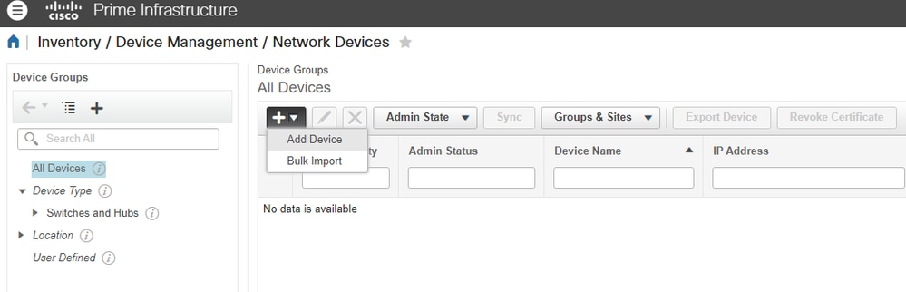
7. Add the Network Device in Inventory > Device Management > Network Devices > Plus sign (+) > Add Device:
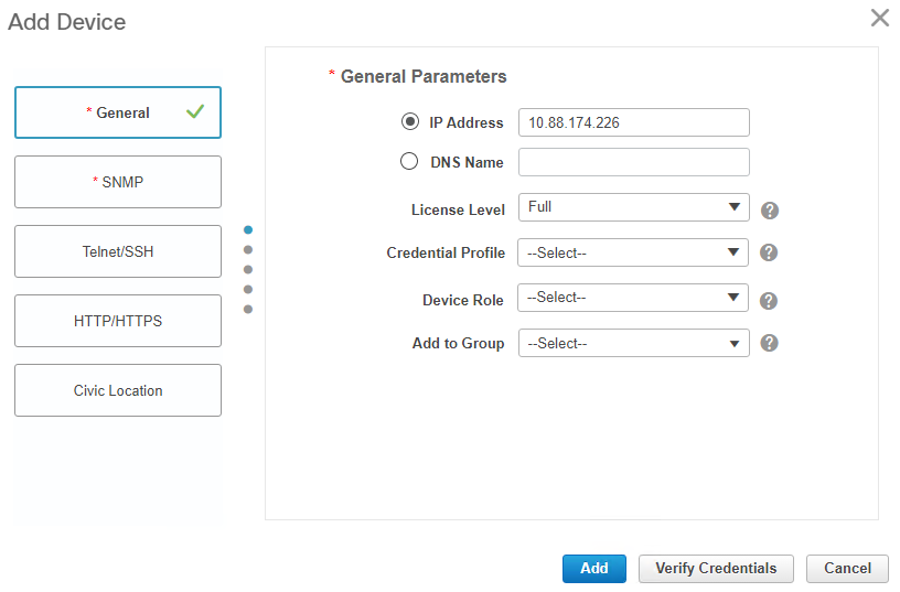
Mandatory fields to get inventory completed are:
For wired devices:
- General: either IP or DNS.
- SNMP: RO community is required - make sure to configure it also in the Switch/WLC.
- Telnet/SSH: Exec mode and enable mode credentials.
For WLC:
- General: either IP or DNS.
- SNMP: RO community is required - make sure to configure it also in the Switch/WLC.
In this guide you are using a Cisco Switch:
i. General section:
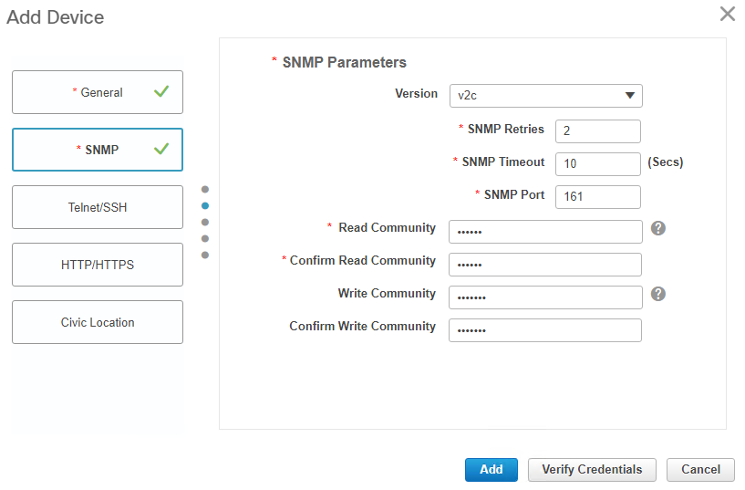
ii. SNMP section:
iii. Telnet/SSH section:
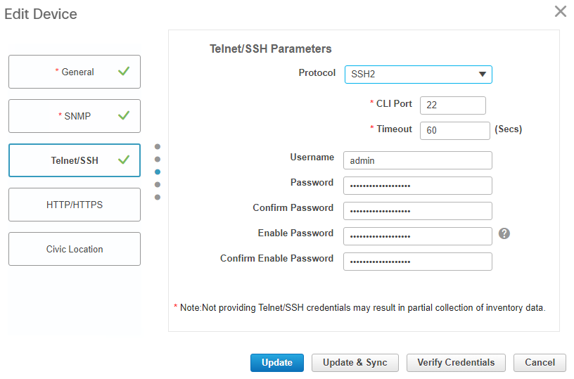
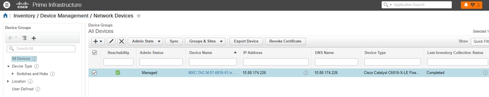
8. Once all required fields are complete, make sure that Reachability and Collection Status are Green and Completed respectively:
9. Integrate Prime with ISE.
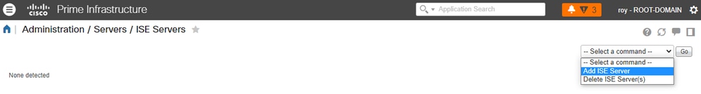
i. Navigate to Administration > Servers > ISE Servers.
ii. In the dropdown menu, select Add ISE Server and then click Go:
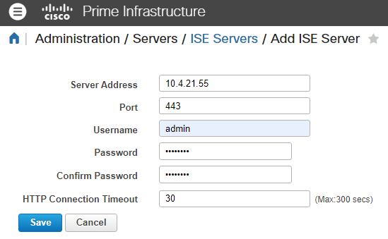
iii. Fill all the fields and click Save.
Note: The connection must be established against the primary and secondary (if applicable) monitoring ISE nodes.
Note: The default port is set to 443, but you can use any other opened port in ISE to establish the connection.
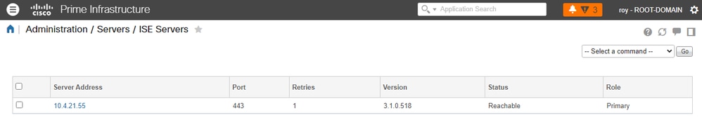
iv. Navigate back to the ISE Server page. The server status says Reachable and the Role is displayed (either Standalone, Primary [MnT] or Secondary [MnT]):
Endpoint Configuration
10. The endpoint must be configured to perform dot1x (RFC 3850) authentication. This can be achieved either by configuring Cisco Network Access Manager (NAM) or leveraging the OS Native Supplicant. There are a plenty of guides regarding this configuration so we are not including those steps in this guide.
Verify
Verify ISE
ISE receives the RADIUS request from the NAD and successfully authenticate the user.
The NAD is added and configured for RADIUS in ISE > Administration > Network Resources > Network Devices.
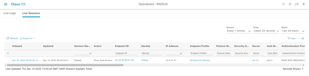
1. Navigate to Operations > RADIUS > Live Sessions.
Make sure the user live session is listed in this page. The session information is shared with Prime Infrastructure.
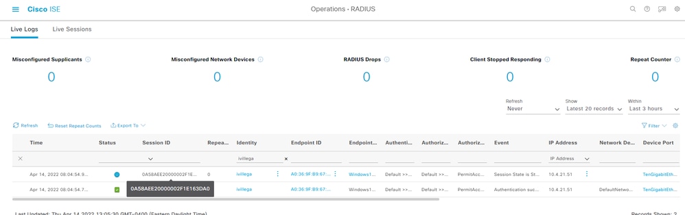
2. Check the Session ID in Operations > RADIUS > Live Logs:
Verify the NAD
3. Check the session details in the NAD. The session ID matches the session ID in ISE:
MXC.TAC.M.07-6816-01#show authentication session int Te1/11 detail
        Interface: TenGigabitEthernet1/11
      MAC Address: a036.9fb9.67ea
     IPv6 Address: Unknown
     IPv4 Address: 10.4.21.51
        User-Name: ivillega
           Status: Authorized
           Domain: DATA
   Oper host mode: multi-domain
 Oper control dir: both
  Session timeout: N/A
Common Session ID: 0A58AEE20000002F1E163DA0
  Acct Session ID: 0x00000023
           Handle: 0xD9000001
   Current Policy: POLICY_Te1/11

Method status list:
        Method     State
        dot1x      Authc Success
Verify Prime Infrastructure
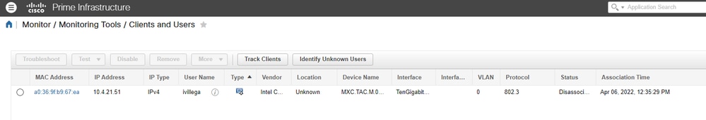
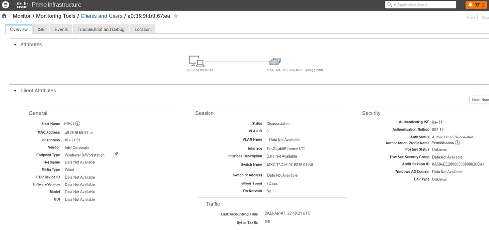
4. Navigate to Monitor > Monitoring Tools > Clients and Users. The MAC address of the endpoint is displayed:
5. If you click it, you see the user session details and the ISE server information:
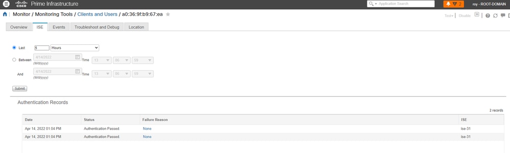
6. There is also a tab labeled as ISE to retrieve the session events for this particular endpoint. You can select a time-frame that Prime Infrastructure uses to fetch events from ISE:
Troubleshoot
1. Test connectivity between ISE and Prime Infrastructure with pings. If there is no connectivity, you can use trace routes either from ISE or PI to locate the issue.
2. Check that port configured in Step 9 is opened in ISE MnT node (default port is 443):
ise-31-1/admin# show ports | include :443
     tcp: 0.0.0.0:80, 0.0.0.0:19444, 0.0.0.0:19001, 0.0.0.0:443
If the port is listed in the output, that means ISE MnT has the port opened.
If there is no output or the port is not listed, that means ISE MnT has that port closed. In such case, you can try with another port or open a TAC case with ISE team to check why the port is not opened.
Note: ISE MnT node only uses some ports, there is no way to open ports in ISE MnT node that are not listed in the ISE installation guide, Port reference section.
3. Test the port configured in Step 9 with Telnet from Prime infrastructure:
prime-testcom/admin# telnet 10.4.21.55 port 443
Trying 10.4.21.55...
Connected to 10.4.21.55.
If the output of the telnet test is Connected to <ISE MnT IP/FQDN>, that means the test was successful.
If the output of the telnet test is stuck at Trying <ISE MnT IP/FQDN>, that means the test failed. This can be related to ACLs in your intermediary network devices or with Firewall rules.
 Feedback