Troubleshoot Layer 2 VPN Virtual Private LAN Service on IOS XE
Available Languages
Contents
Introduction
This document describes how to troubleshoot Layer 2 VPN Virtual Private LAN Service (VPLS) on Technologies for Cisco IOS® XE.
Prerequisites
Requirements
Cisco recommends that you have knowledge of these topics:
- Basic IP Routing
- Layer 2 VPN Virtual Private LAN Service
Components Used
The information in this document is based on Cisco IOS XE software.
The information in this document was created from the devices in a specific lab environment. All of the devices used in this document started with a cleared (default) configuration. If your network is live, ensure that you understand the potential impact of any command.
Network Diagram
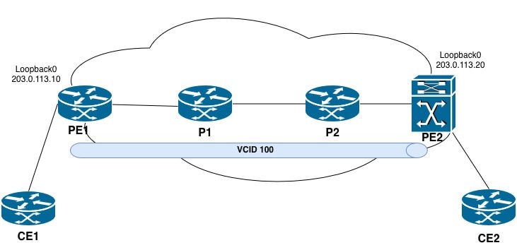 VPLS Topology
VPLS Cross-Connect Is Not Operational
Troubleshooting Steps
The VPLS cross-connect is in a down state after the session was terminated unexpectedly.
PE2#show xconnect all
Legend: XC ST=Xconnect State S1=Segment1 State S2=Segment2 State
UP=Up DN=Down AD=Admin Down IA=Inactive
SB=Standby HS=Hot Standby RV=Recovering NH=No Hardware

XC ST  Segment 1                         S1 Segment 2                         S2
------+---------------------------------+--+---------------------------------+--
DN pri vfi 100                           UP mpls 203.0.113.10:100             DN
UP pri ac Vl100:100(Eth VLAN)            UP vfi 100                           UP
UP pri bd 100                            UP vfi 100                           UP
Step 1. Confirm the exact VC/VPLS state.
PE2#show mpls l2transport vc 100 detail
Local interface: VFI 100 vfi up
   Interworking type is Ethernet
   Destination address: 203.0.113.10, VC ID: 100, VC status: down
     Last error: Local access circuit is not ready for label advertise << The local device is unable to advertise labels because the access circuit (AC) is not in a ready state.
     Output interface: none, imposed label stack {} << no MPLS labels are being imposed because no path exists.
     Preferred path: not configured << No explicit traffic engineering path is configured for this pseudowire.
     Default path: no route << No route to the remote PE (203.0.113.10) exists in the routing table.
     No adjacency
Create time: 10:50:35, last status change time: 00:17:39
  Last label FSM state change time: 00:17:33
Signaling protocol: LDP, peer x.x.x.x:0 up
  Targeted Hello: 203.0.113.20(LDP Id) -> 203.0.113.10, LDP is DOWN, no binding
  Graceful restart: not configured and not enabled
  Non stop routing: not configured and not enabled
  Status TLV support (local/remote) : enabled/None (no remote binding
    LDP route watch : enabled
    Label/status state machine : local ready, LruRnd
    Last local dataplane status rcvd: No fault
    Last BFD dataplane status rcvd: Not sent
    Last BFD peer monitor status rcvd: No fault
    Last local AC circuit status rcvd: No fault
    Last local AC circuit status sent: DOWN(hard-down) << The local device is advertising the access circuit as hard-down to the remote PE.
    Last local PW i/f circ status rcvd: No fault
    Last local LDP TLV status sent: No fault
    Last remote LDP TLV status rcvd: None (no remote binding) << No status has been received from the remote PE.
    Last remote LDP ADJ status rcvd: None (no remote binding) << No adjacency status received from the remote peer.
  MPLS VC labels: local 16, remote unassigned
  Group ID: local n/a, remote unknown
  MTU: local 1500, remote unknown
  Remote interface description:
Sequencing: receive disabled, send disabled
Control Word: On (configured: autosense)
SSO Descriptor: 203.0.113.10/100, local label: 16
Dataplane:
  SSM segment/switch IDs: 0/8194 (used), PWID: 1
VC statistics:
  transit packet totals: receive 0, send 0
  transit byte totals: receive 0, send 0
  transit packet drops: receive 0, seq error 0, send 0
The VPLS cross-connect (VC ID 100) has transitioned to a down state. The root cause is attributed to the conditions described:
1. No route to the remote PE - The router does not have a route to 203.0.113.10 in the routing table (Default path: no route). Without a valid route, no MPLS label-switched path (LSP) can be established.
2. Targeted LDP session is down - The targeted LDP session from 203.0.113.20 to 203.0.113.10 is not established. This prevents the exchange of pseudowire labels between the PE routers.
3. No remote label binding - Because the targeted LDP session is down, no remote label has been assigned for VC 100. The pseudowire cannot forward traffic without both local and remote labels.
4. No adjacency - Without a valid route and LDP session, no MPLS adjacency exists toward the remote PE.
Step 2. Check the local attachment circuit.
On the PE where the VC is down:
PE2#show interfaces vlan 100 | include up|errors
Vlan100 is up, line protocol is up , Autostate Disabled
Keepalive not supported
0 input errors, 0 CRC, 0 frame, 0 overrun, 0 ignored
0 output errors, 1 interface resets

PE2#show running-config interface vlan 100
Building configuration...

Current configuration : 72 bytes
!
interface Vlan100
no ip address
no autostate
xconnect vfi 100
end
Step 3. Verify the VFI configuration.
PE2#show running-config | section l2 vfi
l2 vfi 100 manual
vpn id 100
neighbor 203.0.113.10 pw-class VPLS_100

PE2#show l2vpn vfi
Legend: RT=Route-target, S=Split-horizon, Y=Yes, N=No

VFI name: 100, state: up, type: multipoint, signaling: LDP
  VPN ID: 100
  Bridge-Domain 100 attachment circuits:
    Vlan100
  Pseudo-port interface: pseudowire100001
  Interface Peer Address VC ID S
  pseudowire100002 203.0.113.10 100 Y
Key Observations
1. VFI is operationally up - The local VFI instance is active and ready to forward traffic.
2. Attachment circuit is bound - Vlan100 is correctly associated with Bridge-Domain 100 and the VFI.
3. Pseudowire is configured - A pseudowire (pseudowire100002) is defined toward the remote PE at 203.0.113.10 with VC ID 100.
4. Split-horizon is enabled - This is expected behavior in a VPLS multipoint environment to prevent Layer 2 loops.
Step 4. Verify PE loopback reachability:
PE2#ping 203.0.113.10
Type escape sequence to abort.
Sending 5, 100-byte ICMP Echos to 203.0.113.10, timeout is 2 seconds:
!!!!!
Success rate is 100 percent (5/5), round-trip min/avg/max = 1/1/1 ms

PE2#show ip route 203.0.113.10
Routing entry for 203.0.113.10/32
Known via "ospf 1", distance 110, metric 2, type intra area
Last update from 192.0.2.9 on TwentyFiveGigE1/0/3, 00:01:30 ago
Routing Descriptor Blocks:
* 192.0.2.9, from 198.51.100.2, 00:01:30 ago, via TwentyFiveGigE1/0/3
Route metric is 2, traffic share count is 1

PE2#ping mpls ipv4 203.0.113.10/32 source 203.0.113.20
Sending 5, 72-byte MPLS Echos to 203.0.113.10/32,
timeout is 2 seconds, send interval is 0 msec:

Codes: '!' - success, 'Q' - request not sent, '.' - timeout,
'L' - labeled output interface, 'B' - unlabeled output interface,
'D' - DS Map mismatch, 'F' - no FEC mapping, 'f' - FEC mismatch,
'M' - malformed request, 'm' - unsupported tlvs, 'N' - no label entry,
'P' - no rx intf label prot, 'p' - premature termination of LSP,
'R' - transit router, 'I' - unknown upstream index,
'l' - Label switched with FEC change, 'd' - see DDMAP for return code,
'X' - unknown return code, 'x' - return code 0

Type escape sequence to abort.
!!!!!
Success rate is 100 percent (5/5), round-trip min/avg/max = 1/1/2 ms
Total Time Elapsed 8 ms
Standard Ping Versus MPLS LSP Ping: Key Distinctions
A standard ping can succeed even when the MPLS LSP is broken because:
• The ICMP packet can be IP-routed (not label-switched) if the destination is directly reachable via IP.
• Transit routers can forward the ICMP packet using IP lookup if no label is imposed.
Conversely, ping mpls ipv4 validates the actual MPLS data plane by forcing the packet through the label-switched path. This ensures that:
• Labels are correctly allocated and distributed.
• The LFIB entries are consistent at each hop.
• The LSP end-to-end path is functional.
Step 5. Verify MPLS and LDP in the core:
PE2#show mpls ldp neighbor
    Peer LDP Ident: 203.0.113.10:0; Local LDP Ident 203.0.113.20:0
        TCP connection: 203.0.113.10.646 - 203.0.113.20.39001
        State: Oper; Msgs sent/rcvd: 16/15; Downstream
        Up time: 00:02:15
        LDP discovery sources:
          TwentyFiveGigE1/0/3, Src IP addr: 192.0.2.9
          Targeted Hello 203.0.113.20 -> 203.0.113.10, active, passive
        Addresses bound to peer LDP Ident:
          203.0.113.10 192.0.2.6 192.0.2.9
This command presents the LDP neighbor session information between the local router (PE2) and the remote peer. Each field in the output is described in detail.
- Peer Identification:
Peer LDP Ident | 203.0.113.10:0 | The LDP router ID of the remote peer. The :0 indicates the default platform-wide label space. This is typically the loopback address of the remote router.
Local LDP Ident | 203.0.113.20:0 | The LDP router ID of the local router (PE2). This is typically the loopback address of PE2.
- TCP Session Information:
TCP connection | 203.0.113.10.646 - 203.0.113.20.39001 | The TCP session used for LDP communication. The remote peer (203.0.113.10) uses the well-known LDP port 646, and the local router (203.0.113.20) uses ephemeral port 39001. LDP uses TCP for reliable label distribution.
- Session State:
State | Oper | The LDP session is in an operational state, meaning the session is fully established and functional.
Msgs sent/rcvd | 16/15 | The number of LDP messages sent (16) and received (15) since the session was established. This includes keepalives, label mappings, and other LDP messages.
Downstream | - | Indicates the label distribution mode. Downstream Unsolicited means the peer distributes labels to PE2 without PE2 explicitly requesting them. This is the default mode for LDP.
Up time | 00:02:15 | The session has been operational for 2 minutes and 15 seconds. - LDP Discovery Sources:
TwentyFiveGigE1/0/3 | Src IP addr: 192.0.2.9 | A basic discovery (link-level) hello is received from the peer on interface TwentyFiveGigE1/0/3 with a source IP address of 192.0.2.9. This indicates that the two routers are directly connected on this interface.
Targeted Hello | 203.0.113.20 → 203.0.113.10, active, passive | A targeted discovery (extended) hello exists between the local router (203.0.113.20) and the remote peer (203.0.113.10). - Addresses Bound to Peer LDP Ident:
Addresses bound to peer | 203.0.113.10, 192.0.2.6, 192.0.2.9 | The list of IP addresses that the remote peer has advertised via LDP Address messages. These represent the interfaces on the remote router.
Step 5.1 Verify the MPLS Label-Switched Path to the Remote VPLS Peer
PE2#show mpls forwarding-table 203.0.113.10
Local        Outgoing         Prefix               Bytes Label     Outgoing          Next Hop
Label        Label            or Tunnel Id         Switched        interface
25           Pop Label        203.0.113.10/32      0                Twe1/0/3         192.0.2.9

PE2#show mpls ldp bindings 203.0.113.10 32
  lib entry: 203.0.113.10/32, rev 69
        local binding: label: 25
        remote binding: lsr: 203.0.113.10:0, label: imp-null
PE2 receives imp-null directly from PE1, bypassing the expected label path through P2 and P1. This indicates a missing LDP session or MPLS configuration issue between PE2 and P2.
Step 5.2 Validate the next-hop information by executing the commands provided:
- show mpls ldp neighbor
- show mpls forwarding-table
P2#show mpls forwarding-table 203.0.113.10
Local        Outgoing          Prefix Bytes          Label           Outgoing       Next Hop
Label        Label             or Tunnel Id          Switched        interface
None         No Label          203.0.113.10/32       0
Key Observation
- Local label: None | P2 has not allocated a local label for this prefix.
- Outgoing label: No Label | No label operation is performed.
- No outgoing interface or next hop | The prefix is treated as locally owned - no forwarding toward PE1 occurs.
P2#show mpls ldp neighbor
    Peer LDP Ident: 203.0.113.20:0; Local LDP Ident 198.51.100.2:0
        TCP connection: 203.0.113.20.17326 - 198.51.100.2.646
        State: Oper; Msgs sent/rcvd: 30/29; Downstream
        Up time: 00:13:57
        LDP discovery sources:
           GigabitEthernet0/0/1, Src IP addr: 192.0.2.10
        Addresses bound to peer LDP Ident:
          203.0.113.20 192.0.2.10
Peer LDP Ident: 198.51.100.1:0; Local LDP Ident 198.51.100.2:0
    TCP connection: 198.51.100.1.646 - 198.51.100.2.12799
    State: Oper; Msgs sent/rcvd: 30/28; Downstream
    Up time: 00:13:56
    LDP discovery sources:
      GigabitEthernet0/0/0, Src IP addr: 192.0.2.5
    Addresses bound to peer LDP Ident:
      192.0.2.2 192.0.2.5 198.51.100.1

P2#show ip ospf neighbor

Neighbor ID       Pri   State           Dead Time    Address           Interface
198.51.100.3        0   FULL/ -         00:00:34     192.0.2.10        GigabitEthernet0/0/1
198.51.100.1        0   FULL/ -         00:00:34     192.0.2.5         GigabitEthernet0/0/0
Key Observation
- P2 does not have a direct LDP adjacency with PE1 (203.0.113.10). This is expected, as P1 resides between P2 and PE1 in the topology. P2 is responsible for label-switching traffic toward P1, which then forwards it to PE1.
- P2's LDP Ident is 198.51.100.2:0 | P2 uses 198.51.100.2 as its LDP router ID, not 203.0.113.10. However, 203.0.113.10 is still configured on Loopback10 and causes a routing conflict.
Step 6. Verify the route to the remote PE loopback address:
P2#show ip route 203.0.113.10
Routing entry for 203.0.113.10/32
  Known via "connected", distance 0, metric 0 (connected, via interface)
  Routing Descriptor Blocks:
  * directly connected, via Loopback10
      Route metric is 0, traffic share count is 1
Conclusion
- Duplicate IP address - The IP address 203.0.113.10 is configured on P2 (Loopback10) and PE1 (Loopback0), which creates a conflict in the MPLS domain.
- Routing conflict - P2 installs 203.0.113.10/32 as a connected route (administrative distance 0), which takes precedence over any IGP-learned route originated by PE1.
- LSP failure - Because P2 considers the prefix as locally owned, it does not allocate or advertise a transport label for 203.0.113.10/32 to PE2.
- VPLS impact - The absence of a valid transport label from P2 prevents PE2 from establishing an LSP to PE1. As a result, the VPLS pseudowire transport path cannot be formed.
VPLS Cross-Connect Established but No Data Traffic Traverses the Pseudowire
VPLS Operational Verification for Catalyst 9000 Series
Troubleshooting Steps
Step 1. Confirm that the pseudowire is in an operational state.
Ensure the parameters are correct:
- VFI state is up
- The pseudowire interface is listed
- The correct peer address and VC ID are displayed
PE2#show mpls l2transport vc

Local intf    Local circuit              Dest address    VC ID      Status
------------- -------------------------- --------------- ---------- ----------
VFI 100        vfi                       203.0.113.10    100        UP
PE2#show mpls l2transport vc 100 detail
Local interface: VFI 100 vfi up
  Interworking type is Ethernet
  Destination address: 203.0.113.10, VC ID: 100, VC status: up
    Output interface: Twe1/0/3, imposed label stack {17 16}
    Preferred path: not configured
    Default path: active
    Next hop: 192.0.2.9
Create time: 1d11h, last status change time: 00:30:50
  Last label FSM state change time: 00:30:26
Signaling protocol: LDP, peer 203.0.113.10:0 up
  Targeted Hello: 203.0.113.20(LDP Id) -> 203.0.113.10, LDP is UP
  Graceful restart: not configured and not enabled
  Non stop routing: not configured and not enabled
  Status TLV support (local/remote) : enabled/supported
    LDP route watch : enabled
    Label/status state machine : established, LruRru
    Last local dataplane status rcvd: No fault
    Last BFD dataplane status rcvd: Not sent
    Last BFD peer monitor status rcvd: No fault
    Last local AC circuit status rcvd: No fault
    Last local AC circuit status sent: No fault
    Last local PW i/f circ status rcvd: No fault
    Last local LDP TLV status sent: No fault
    Last remote LDP TLV status rcvd: No fault
    Last remote LDP ADJ status rcvd: No fault
  MPLS VC labels: local 16, remote 16
  Group ID: local n/a, remote 0
  MTU: local 1500, remote 1500
  Remote interface description:
  MAC Withdraw: sent:1, received:0
Sequencing: receive disabled, send disabled
Control Word: On (configured: autosense)
SSO Descriptor: 203.0.113.10/100, local label: 16
Dataplane:
  SSM segment/switch IDs: 16395/8194 (used), PWID: 1
VC statistics:
transit packet totals: receive 0, send 0
transit byte totals: receive 0, send 0
transit packet drops: receive 0, seq error 0, send 0
- VFI status | up | The VFI is operationally up on the local device.
- Destination address | 203.0.113.10 | The remote PE router ID (PE1 loopback address).
- VC ID | 100 | The virtual circuit identifier for this pseudowire. Must match on both PE routers.
- VC status | up | The pseudowire is operationally up. Both local and remote signaling indicate no faults.
- Imposed label stack {17 16} | The two-label MPLS stack imposed on packets entering the pseudowire. Label 17 is the transport label (outer) used to reach the remote PE across the MPLS core. Label 16 is the VC label (inner) used to identify the pseudowire at the remote PE.
- Targeted Hello | 203.0.113.20 → 203.0.113.10, LDP is UP | The targeted LDP session between PE2 (local) and PE1 (remote) is established and operational.
- Local label | 16 | The VC label allocated by PE2 for this pseudowire. The remote PE (PE1) uses this label when sending traffic to PE2. Remote label | 16 | The VC label advertised by PE1 for this pseudowire. PE2 imposes this label (inner label) when sending traffic to PE1.
- MAC Withdraw sent | 1 | PE2 has sent 1 MAC withdraw message to the remote PE. This is used to flush MAC address tables after a topology change.
- MAC Withdraw received | 0 | No MAC withdraw messages have been received from the remote PE.
- VC Statistics | no traffic is being forwarded in either direction (send: 0, receive: 0).
Step 2. Verify the attachment circuit (trunk interface) status.
Confirm that the trunk interface is operational and associated with the correct VLAN.
Verify:
- The interface is in an up/up state
- The VLAN associated with the VPLS bridge domain is allowed and active on the trunk
- The VLAN is not pruned or blocked by STP
PE2#show interfaces twentyFiveGigE 1/0/2 status
Port       Name        Status        Vlan          Duplex       Speed  Type
Twe1/0/2               connected     trunk           full         10G  SFP-10GBase-SR
PE2#show interfaces trunk
Port         Mode        Encapsulation   Status       Native vlan
Twe1/0/2     on          802.1q          trunking     1

Port         Vlans allowed on trunk
Twe1/0/2     100

Port         Vlans allowed and active in management domain
Twe1/0/2     100

Port         Vlans in spanning tree forwarding state and not pruned
Twe1/0/2     100
Step 3. Verify vlan association with the bridge domain.
On the Catalyst 9000 with a trunk configuration (no EVC), the vlan must be mapped to the bridge domain.
Confirm:
- The VLAN is associated with the bridge domain via the member vfi or member configuration.
- The bridge-domain configuration references the correct VFI.
PE2#show running-config interface vlan100
Building configuration...

Current configuration : 72 bytes
!
interface Vlan100
no ip address
xconnect vfi 100
Step 4. Verify MAC address learning.
Confirm that MAC addresses from both the local attachment circuit and the remote pseudowire are being learned.
Verify:
- The local CE1 MAC address is learned on the trunk interface.
- The remote CE2 MAC address is learned on the pseudowire interface.
If no MAC addresses are learned on the pseudowire:
- Traffic is not received from the remote PE.
- The remote PE has a configuration issue that prevents traffic from entering the pseudowire.
- The bridge domain is not correctly associated with the pseudowire interface.
If no MAC addresses are learned on the local trunk:
- The CE device is not transmitting traffic on the expected VLAN.
- The VLAN is in a blocked or inactive state on the trunk interface.
PE2#show mac address-table vlan 100
          Mac Address Table
-------------------------------------------

Vlan Mac Address Type     Ports
---- ----------- -------- -----
100 cc7f.76b7.525f STATIC Vl100
100 e462.c4bb.17f1 DYNAMIC Twe1/0/2  >> CE2 Mac address learned over Twe1/0/2 interface.
Step 5. Verify spanning tree Ppotocol (STP) state.
STP can block the VLAN on the trunk interface, which prevents traffic from entering the bridge domain.
Verify:
• The trunk port is in a forwarding state for the VLAN associated with the VPLS bridge domain
• The port is not in a blocking, listening, or learning state
If STP is blocking the port:
• Adjust STP priority or port cost
• Consider configuring the trunk port as an STP edge port (if appropriate for the topology)
PE2#show spanning-tree vlan 100

VLAN0100
  Spanning tree enabled protocol rstp
  Root ID    Priority 32868
           Address cc7f.76b7.51c0
           This bridge is the root
           Hello Time 2 sec Max Age 20 sec Forward Delay 15 sec

Bridge ID  Priority  32868 (priority 32768 sys-id-ext 100)
           Address   cc7f.76b7.51c0
           Hello Time 2 sec Max Age 20 sec Forward Delay 15 sec
           Aging Time 300 sec

Interface           Role Sts Cost      Prio.Nbr Type
------------------- ---- --- --------- -------- --------------------------------
Twe1/0/2            Desg FWD 2000      128.2    P2p
Step 6. Verify the MPLS label stack and forwarding path.
Confirm that the correct labels are imposed and the forwarding path is valid.
Verify:
- A valid outgoing label is present (not No Label or None)
- The outgoing interface and next hop are correct
From PE2 to P2 LSP path:
PE2#show mpls forwarding-table 203.0.113.10 32
Local     Outgoing     Prefix            Bytes Label     Outgoing      Next Hop
Label     Label        or Tunnel Id      Switched        interface
22        17           203.0.113.10/32   810             Twe1/0/3      192.0.2.9 << For the transport path to the remote PE1 loopback, the imposed outgoing label is 17. The router at 192.0.2.9 assigned this value as its local label binding for the destination prefix.
From P2 to P1 LSP path:
P2#show mpls forwarding-table 203.0.113.10 32
Local     Outgoing    Prefix            Bytes Label     Outgoing       Next Hop
Label     Label       or Tunnel Id      Switched        interface
17        16          203.0.113.10/32   79290           Gi0/0/0        192.0.2.5 << Local label as 17 and the imposed outgoing label is 16. The router at 192.0.2.5 assigned this value as its local label binding for the destination prefix.
From P1 to PE1 LSP path:
P1#show mpls forwarding-table 203.0.113.10 32
Local     Outgoing    Prefix            Bytes Label     Outgoing       Next Hop
Label     Label       or Tunnel Id      Switched        interface
16        Pop Label   203.0.113.10/32   76184           Gi0/0/0        192.0.2.1 << Pop Label is performed before forwarding the packet to the next hop. This confirms that the next hop (PE1) advertised implicit null to P1.
From P1 to PE1 LSP path:
PE1#show mpls forwarding-table 203.0.113.10 32
Local      Outgoing   Prefix           Bytes Label         Outgoing       Next Hop
Label      Label      or Tunnel Id     Switched            interface
None       No Label   203.0.113.10/32  0
Label path confirmation:
Based on this output and the previous outputs from PE2 and P2, the complete label-switched path from PE2 to PE1 is:
[PE2] Packet leaves with label stack: | 17 | (transport label)
        ↓
[P2]  Receives label 17, swaps to 16: | 16 | (transport label)
        ↓
[P1]  Receives label 16, pops label:  | IP | (pure IP packet)
        ↓
[PE1] Receives pure IP packet - local delivery
When VPLS traffic traverses this LSP, the packet carries a two-label stack (transport : VC label)
[PE2] Packet leaves with label stack: | 17 | 16 | (transport + VC label)
       ↓
[P2] Receives label 17, swaps to 16:  | 16 | 16 | (transport + VC label)
       ↓
[P1] Receives label 16, pops label:   | 16 | (VC label only)
       ↓
[PE1] Receives VC label 16 - pseudowire disposition into bridge domain
Conclusion
The MPLS transport LSP from PE2 to PE1 is fully operational and correctly programmed across all routers in the path. The VPLS pseudowire signaling is complete, with both local and remote labels exchanged and no faults reported.
However, no user traffic is being forwarded across the pseudowire despite the control plane being fully established. This confirms that the issue resides outside the MPLS core and pseudowire signaling - specifically at the attachment circuit layer on one or both PE routers
VPLS Operational Verification for Routers
Troubleshooting Steps
Step 1. Confirm the exact VC/VPLS state.
Ensure the parameters are correct:
PE1#show mpls l2transport vc

Local intf    Local circuit              Dest address     VC ID     Status
------------- -------------------------- --------------- ---------- ----------
VFI 100        vfi                       203.0.113.20    100         UP
PE1#show mpls l2transport vc 100 detail
Local interface: VFI 100 vfi up
  Interworking type is Ethernet
  Destination address: 203.0.113.20, VC ID: 100, VC status: up
    Output interface: Te0/0/4, imposed label stack {19 16}
    Preferred path: not configured
    Default path: active
    Next hop: 192.0.2.2
  Create time: 1d09h, last status change time: 08:38:02
    Last label FSM state change time: 08:38:25
  Signaling protocol: LDP, peer 203.0.113.20:0 up
    Targeted Hello: 203.0.113.10(LDP Id) -> 203.0.113.20, LDP is UP
    Graceful restart: not configured and not enabled
    Non stop routing: not configured and not enabled
    Status TLV support (local/remote) : enabled/supported
      LDP route watch : enabled
      Label/status state machine : established, LruRru
      Last local dataplane status rcvd: No fault
      Last BFD dataplane status rcvd: Not sent
      Last BFD peer monitor status rcvd: No fault
      Last local AC circuit status rcvd: No fault
      Last local AC circuit status sent: No fault
      Last local PW i/f circ status rcvd: No fault
      Last local LDP TLV status sent: No fault
      Last remote LDP TLV status rcvd: No fault
      Last remote LDP ADJ status rcvd: No fault
    MPLS VC labels: local 16, remote 16
    Group ID: local n/a, remote 0
    MTU: local 1500, remote 1500
    Remote interface description:
    MAC Withdraw: sent:0, received:1
  Sequencing: receive disabled, send disabled
  Control Word: On (configured: autosense)
  SSO Descriptor: 203.0.113.20/100, local label: 20
  Dataplane:
    SSM segment/switch IDs: 8199/4097 (used), PWID: 1
  VC statistics:
    transit packet totals: receive 336, send 0
    transit byte totals:   receive 27552, send 0
    transit packet drops: receive 0, seq error 0, send 0
- VFI status | up | The VFI is operationally up on PE1.
- Destination address | 203.0.113.20 | The remote PE router ID (PE2 loopback address).
- VC ID | 100 | The virtual circuit identifier for this pseudowire. This value matches on both PE routers.
- VC status | up | The pseudowire is operationally up. Both local and remote signaling indicate no faults.
- Local interface | VFI 100 | The local Virtual Forwarding Instance associated with this pseudowire.
- Imposed label stack | {19 16} | The two-label MPLS stack imposed on packets entering the pseudowire. Label 19 is the transport label (outer) used to reach PE2 across the MPLS core. Label 16 is the VC label (inner) used to identify the pseudowire at PE2.
- Targeted Hello | 203.0.113.10 → 203.0.113.20, LDP is UP | The targeted LDP session from PE1 (local) to PE2 (remote) is established and operational.
- Local label | 16 | The VC label allocated by PE1 for this pseudowire. PE2 uses this label (as the inner label) when sending traffic to PE1.
- MAC Withdraw sent | 0 | PE1 has not sent any MAC withdraw messages to PE2.
- MAC Withdraw received | 1 | PE1 has received 1 MAC withdraw message from PE2. This indicates that PE2 experienced a topology change and requested PE1 to flush its MAC address table for this VFI.
- VC Statistics | Transit packets received | 336 | 336 packets have been received from PE2 on this pseudowire.
Transit bytes received | 27,552 | 27,552 bytes have been received from PE2.
Transit packets sent | 0 | No packets have been sent from PE1 into the pseudowire toward PE2.
Transit bytes sent | 0 | No bytes have been sent toward PE2.
Step 2. Verify the Bridge-Domain configuration and membership.
Confirm that the bridge domain has the correct members (Service Instance interface and pseudowire).
PE1#show running-config interface TenGigabitEthernet0/0/5
Building configuration...

Current configuration : 174 bytes
!
interface TenGigabitEthernet0/0/5
no ip address
service instance 100 ethernet
encapsulation dot1q 100
rewrite ingress tag pop 1 symmetric
bridge-domain 100
!
end

PE1#show interfaces tenGigabitEthernet 0/0/5 | include up|errors
TenGigabitEthernet0/0/5 is up, line protocol is up
  Keepalive not supported
  Full Duplex, 10000Mbps, link type is force-up, media type is H10GB-CU1M
     0 input errors, 0 CRC, 0 frame, 0 overrun, 0 ignored
     0 output errors, 0 collisions, 1 interface resets
Step 3. Verify MAC address learning.
Confirm that MAC addresses from both the local attachment circuit and the remote pseudowire are being learned.
PE1#show bridge-domain
Bridge-domain 100 (2 ports in all)
State: UP                 Mac learning: Enabled
Aging-Timer: 300 second(s)
Unknown Unicast Flooding Suppression: Disabled
Maximum address limit: 65536
    TenGigabitEthernet0/0/5 service instance 100
    vfi 100 neighbor 203.0.113.20 100
   AED MAC address Policy Tag Age Pseudoport
-----------------------------------------------------------------------------
The bridge-domain itself is up, but the absence of learned MAC addresses is the key detail. That usually points to no traffic learned yet or a service mapping / forwarding issue somewhere between the local interface, the bridge-domain, and the remote VFI.
Step 4. Verify the VFI configuration:
PE1#show running-config | section vfi
l2 vfi 100 manual
 vpn id 100
 bridge-domain 100
neighbor 203.0.113.20 encapsulation mpls
Step 5. Verify the MPLS transport path.
Perform a quick validation by sending an MPLS traceroute to the remote loopback address.
PE1#traceroute mpls ipv4 203.0.113.20 255.255.255.255 source 203.0.113.10
Tracing MPLS Label Switched Path to 203.0.113.20/32, timeout is 2 seconds

Codes: '!' - success, 'Q' - request not sent, '.' - timeout,
'L' - labeled output interface, 'B' - unlabeled output interface,
'D' - DS Map mismatch, 'F' - no FEC mapping, 'f' - FEC mismatch,
'M' - malformed request, 'm' - unsupported tlvs, 'N' - no label entry,
'P' - no rx intf label prot, 'p' - premature termination of LSP,
'R' - transit router, 'I' - unknown upstream index,
'l' - Label switched with FEC change, 'd' - see DDMAP for return code,
'X' - unknown return code, 'x' - return code 0

Type escape sequence to abort.
0 192.0.2.1 MRU 1500 [Labels: 17 Exp: 0]
L 1 192.0.2.2 MRU 1500 [Labels: 16 Exp: 0] 96 ms
L 2 192.0.2.6 MRU 1500 [Labels: implicit-null Exp: 0] 12 ms
! 3 192.0.2.10 2 ms
The MPLS traceroute output confirms successful establishment of a Label Switched Path (LSP) between the source PE router (203.0.113.10) and the destination PE router (203.0.113.20).
The trace shows label imposition at the ingress PE, label swapping operations across transit Label Switch Routers (LSRs), and Penultimate Hop Popping (PHP) prior to reaching the egress PE.
Specifically:
- Hop 0 indicates that label 17 is imposed for traffic destined to the target FEC.
- Hop 1 shows a label swap operation from 17 to 16, confirming MPLS forwarding through the core.
- Hop 2 advertises implicit-null, indicating that PHP is being performed by the penultimate router.
- Hop 3 successfully reaches the destination, indicated by the "!" return code.
The traceroute does not report any MPLS forwarding anomalies such as missing label bindings, FEC mismatches, premature LSP termination, or unsupported label operations.
PE1
Push 17
  ↓
P1
Swap 17 → 16
  ↓
P2
Pop label
  ↓
PE2 receives pure IP packet
Step 6. Validate the Pseudowire Dataplane.
PE1#ping mpls pseudowire 203.0.113.20 100 source 203.0.113.10
Sending 5, 72-byte MPLS Echos to 203.0.113.20,
timeout is 2 seconds, send interval is 0 msec:

Codes: '!' - success, 'Q' - request not sent, '.' - timeout,
'L' - labeled output interface, 'B' - unlabeled output interface,
'D' - DS Map mismatch, 'F' - no FEC mapping, 'f' - FEC mismatch,
'M' - malformed request, 'm' - unsupported tlvs, 'N' - no label entry,
'P' - no rx intf label prot, 'p' - premature termination of LSP,
'R' - transit router, 'I' - unknown upstream index,
'l' - Label switched with FEC change, 'd' - see DDMAP for return code,
'X' - unknown return code, 'x' - return code 0

Type escape sequence to abort.
!!!!!
Success rate is 100 percent (5/5), round-trip min/avg/max = 1/1/1 ms
Total Time Elapsed 6 ms
PE2#ping mpls pseudowire 203.0.113.10 100 source 203.0.113.20
Sending 5, 72-byte MPLS Echos to 203.0.113.10,
timeout is 2 seconds, send interval is 0 msec:

Codes: '!' - success, 'Q' - request not sent, '.' - timeout,
'L' - labeled output interface, 'B' - unlabeled output interface,
'D' - DS Map mismatch, 'F' - no FEC mapping, 'f' - FEC mismatch,
'M' - malformed request, 'm' - unsupported tlvs, 'N' - no label entry,
'P' - no rx intf label prot, 'p' - premature termination of LSP,
'R' - transit router, 'I' - unknown upstream index,
'l' - Label switched with FEC change, 'd' - see DDMAP for return code,
'X' - unknown return code, 'x' - return code 0

Type escape sequence to abort.
!!!!!
Success rate is 100 percent (5/5), round-trip min/avg/max = 1/1/2 ms
Total Time Elapsed 9 ms
The MPLS pseudowire data plane is validated successfully by the ping mpls pseudowire test. Since the pseudowire ping succeeds and the bridge-domain learns a remote MAC through VPLS, the issue is more likely on the local attachment circuit or VLAN forwarding path where the expected local MAC address is not being learned.
Conclusion
The successful MPLS pseudowire ping confirms that the MPLS transport LSP and pseudowire label bindings are operational between the local and remote PE routers. The result indicates that MPLS forwarding, label distribution, and pseudowire signaling are functioning correctly and that the remote PE is able to process pseudowire OAM packets for the specified VC.
Based on this result, the MPLS core and pseudowire infrastructure appear operational. If traffic issues persist, further investigation can focus on the attachment circuits, VPLS forwarding behavior, MAC learning, MTU consistency, and CE-facing connectivity rather than the underlying MPLS transport path.
For more information on these topics, see:
- Multiprotocol Label Switching Configuration
- Configuring MPLS Layer 2 VPNs
- Configuring VPLS between Cat9500 and ISR4K
- VPLS with BGP Signaling Tech Note
Revision History
| Revision | Publish Date | Comments |
|---|---|---|
1.0 |
07-Jul-2026
|
Initial Release |

 Feedback
Contact Cisco
- Open a Support Case

- (Requires a Cisco Service Contract)