Cisco ACI Multi-Site Architecture White Paper
Available Languages
Bias-Free Language
The documentation set for this product strives to use bias-free language. For the purposes of this documentation set, bias-free is defined as language that does not imply discrimination based on age, disability, gender, racial identity, ethnic identity, sexual orientation, socioeconomic status, and intersectionality. Exceptions may be present in the documentation due to language that is hardcoded in the user interfaces of the product software, language used based on RFP documentation, or language that is used by a referenced third-party product. Learn more about how Cisco is using Inclusive Language.
With the increasing adoption of Cisco Application Centric Infrastructure (Cisco ACI) as a pervasive fabric technology, enterprises and service providers commonly need to interconnect separate Cisco ACI fabrics. Business requirements (business continuance, disaster avoidance, etc.) lead to the deployment of separate data center fabrics, and these need to be interconnected with each other. Depending on the deployment option used (and as explained in this document), these fabrics may be called pods or fabrics and sites.
Note: To best understand the design presented in this document, readers should have at least a basic understanding of Cisco ACI and how it works and is designed for operation in a single site or pod. For more information, see the Cisco ACI white papers available at the following link: https://www.cisco.com/c/en/us/solutions/data-center-virtualization/application-centric-infrastructure/white-paper-listing.html.
Figure 1 shows the architectural options to extend connectivity and policy enforcement between different ACI networks that have been offered from the launch of Cisco ACI up to today.
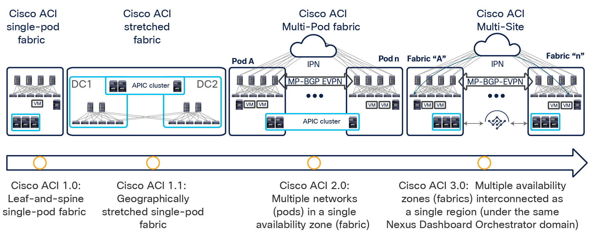
Cisco ACI connectivity options and policy domain evolution
● The first option, available from Cisco ACI Release 1.0, consists of a classic leaf-and-spine two-tier fabric (a single pod) in which all the deployed leaf nodes are fully meshed with all the deployed spine nodes. A single instance of Cisco ACI control-plane protocols runs between all the network devices within the pod. The entire pod is under the management of a single Cisco Application Policy Infrastructure Controller (APIC) cluster, which also represents the single point of policy definition.
● The next step in the evolution of Cisco ACI geographically stretches a pod across separate physical data center locations, usually deployed in the same metropolitan area. Given the common limited availability of fiber connections between those locations, the stretched fabric uses a partial mesh topology, in which some leaf nodes (called transit leaf nodes) are used to connect to both the local and remote spine nodes, and the rest of the leaf nodes connect only to the local spine nodes. Despite the use of partial mesh connectivity, functionally the stretched fabric still represents a single-pod deployment, in which a single instance of all the Cisco ACI control-plane protocols run across all the interconnected data center sites, and so creates a single failure domain.
Note: For more information about the Cisco ACI stretched-fabric deployment option, refer to the following link: https://www.cisco.com/c/en/us/td/docs/switches/datacenter/aci/apic/sw/kb/b_kb-aci-stretched-fabric.html.
● To address the concerns about extending a single network fault domain across the entire stretched-fabric topology, Cisco ACI Release 2.0 introduced the Cisco ACI Multi-Pod architecture. This model calls for the deployment of separate Cisco ACI pods, each running separate instances of control-plane protocols and interconnected through an external IP routed network (or Interpod Network [IPN]). The Cisco ACI Multi-Pod design offers full resiliency at the network level across pods, even if the deployment remains functionally a single fabric, with all the nodes deployed across the pods under the control of the same APIC cluster. Each pod can hence be considered as a separate availability zone; all the pods under the control of the same APIC cluster are part of the same fabric (region).
The main advantage of the Cisco ACI Multi-Pod design is hence operational simplicity, with separate pods managed as if they were logically a single entity. This approach implies that all the Cisco ACI functions available in single-pod deployments (network service chaining, microsegmentation, Virtual Machine Manager [VMM] domain integration, etc.) can be deployed seamlessly across pods: a unique value provided by this architecture. Note, though, that because a Cisco ACI Multi-Pod architecture is managed as a single fabric (APIC domain), it represents a single tenant change domain, in which any configuration and policy changes applied in the context of a given tenant are immediately applied across all the pods. Although this behavior contributes to the operational simplicity of a Multi-Pod design, it also raises concerns about the propagation of configuration errors.
Note: Changes are applied immediately across all the pods, but only in the context of a given tenant. The implicit multitenant nature of a Cisco ACI fabric helps ensure complete isolation for all the resources deployed in separate tenants, shielding them from errors and disruptive events. For more information about the Cisco ACI Multi-Pod design, refer to the following link: https://www.cisco.com/c/en/us/solutions/collateral/data-center-virtualization/application-centric-infrastructure/white-paper-c11-737855.html.
Additionally, a maximum latency of 50 msec RTT can be supported between pods starting from Cisco ACI Release 2.3(1). In previous Cisco ACI releases, this limit is 10 msec RTT instead.
● The need for complete isolation (both at the network and tenant change-domain levels) across separate Cisco ACI networks led to the Cisco ACI Multi-Site architecture, introduced in Cisco ACI Release 3.0(1). This architecture is the main focus of this document and will be discussed in detail in the following sections.
● The same architectural approach taken for ACI Multi-Site has also been extended to provide connectivity and policy extension between on-premises ACI fabrics and public cloud resources (integration with AWS and Azure is supported at the time of writing of this document).
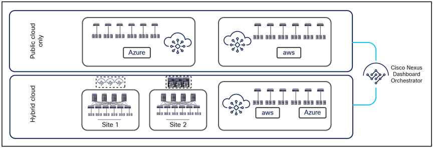
Support for hybrid-cloud and public cloud only deployment options
As shown above, both hybrid-cloud (that is, on-premises ACI fabrics connecting to public cloud resources) and public-cloud-only scenarios are currently supported. Describing those deployment options more in detail is out of the scope of this paper. For more information, please refer to the white papers below:
Before exploring the details of the Cisco ACI Multi-Site design, you should understand why Cisco uses both Multi-Pod and Multi-Site architectures and how you can position them to complement each other to meet different business requirements. To start, you should understand the main terminology used in this document and leveraging some naming conventions heavily utilized in AWS public cloud deployments.
● Pod: A pod is a leaf-and-spine network sharing a common control plane (Intermediate System–to–Intermediate System [ISIS], Border Gateway Protocol [BGP], Council of Oracle Protocol [COOP], etc.). A pod is hence a single network fault domain that can be compared with an AWS availability zone.
◦ Fabric: A fabric is the set of leaf and spines nodes under the control of the same APIC domain. Each fabric represents a separate tenant change domain, because every configuration and policy change applied in the APIC is applied to a given tenant across the fabric. A fabric can hence be compared to an AWS Region.
● Multi-Pod: A Multi-Pod design consists of a single APIC domain with multiple leaf-and-spine networks (pods) interconnected. As a consequence, a Multi-Pod design is functionally a fabric (an interconnection of availability zones), but it does not represent a single network failure domain, because each pod runs a separate instance of control-plane protocols. A Multi-Pod fabric can hence be compared to an AWS region interconnecting different AWS availability zones.
◦ Multi-Site: A Multi-Site design is the architecture interconnecting multiple APIC cluster domains with their associated pods. A Multi-Site design could also be called a Multi-Fabric design, because it interconnects separate regions (fabrics) each deployed as either a single pod or multiple pods (a Multi-Pod design).
Note: Do not confuse the term “Multi-Fabric design” used here to identify the Multi-Site architecture discussed in this document with the term “dual-fabric design,” which refers to a precursor of the Multi-Site design. When operating more than one ACI Fabric, it is highly recommended to deploy Multi-Site instead of interconnecting multiple individual ACI fabric to each other via leaf switches (dual-fabric design). Although the latter option may have been one of the only ways prior to these features, it is currently officially not supported because no validations and quality assurance tests are performed in such topologies specifically when deployed in conjunction with a separate Data Center Interconnect (DCI) technology (such as OTV, VPLS, etc.) allowing extension of Layer 2 domains across sites. Hence, although ACI has a feature called Common Pervasive Gateway for interconnecting ACI fabrics prior to Multi-Site, it is highly recommended to design a new ACI Multi-Fabric deployment with Multi-Site instead when there is a requirement to extend Layer 2 between separate APIC domains.
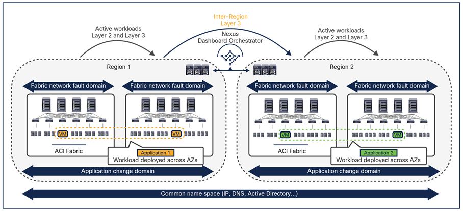
An understanding of AWS constructs as availability zones and regions is essential to understanding why Cisco decided to invest in a Multi-Site architecture after having already delivered the Cisco ACI Multi-Pod design. Organizations typically need to deploy different instances of applications across data center fabrics representing separate regions. This setup is critical to help ensure that any network-level failures or configuration or policy definition errors that occur in one region will not be propagated to the application’s workloads running in a separate region; thus reinforcing both disaster-avoidance and disaster-recovery capabilities.
The deployment of Cisco ACI Multi-Pod and Multi-Site architectures thus can be combined to meet two different requirements. You can create a group of flexible Cisco ACI islands that can be seen and operated as a single logical entity (fabric or region) and used to deploy the functional components of a given application in a classic active/active model (that is, different endpoints building the application tiers can be freely deployed across availability zones that are part of the same fabric). You then can also reliably interconnect and scale those fabrics to be able to deploy different application instances in separate regions (a per-application active/active deployment model that is used for disaster-avoidance requirements) or to provide full application-recovery capabilities across them (a disaster recovery use case). See Figure 3.
Change and network fault domains isolation
Note: The combined deployment of a Cisco ACI Multi-Pod and Multi-Site architecture shown above is supported in Cisco ACI Release 3.2(1) and later.
In lower-scale deployments, it is also quite common for customers to use the same two data center locations for addressing disaster-avoidance and disaster-recovery requirements. Combining ACI Multi-Pod with ACI Multi-Site also allows you to handle also those specific requirements, providing support at the same time for a classic active/active application deployment across sites and a typical application recovery mechanism required in disaster recovery scenarios (Figure 4).
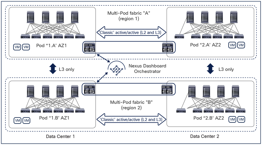
Combined deployment of Cisco ACI Multi-Pod and Multi-Site architectures
The specific deployment of Multi-Site shown in the previous two figures as a means to interconnect at Layer 3 separate fabrics (regions), leaving at Multi-Pod the duty of providing Layer 2 extension services should be the preferred and recommended model. That said, and as it would be made clear in the rest of this paper, Multi-Site also offers native Layer 2 extension capabilities that allow to position this architecture to address some of the specific use cases where usually Multi-Pod could be considered a better fit. When doing so, it is important to keep into considerations some of the functional restrictions that may be encountered (as it is the case for example to integrate FW or SLB clusters into Multi-Site).
The remainder of this document focuses on the Cisco ACI Multi-Site architecture, starting with an overview of its functional components.
Cisco ACI Multi-Site architecture
The overall Cisco ACI Multi-Site architecture is shown in Figure 5.
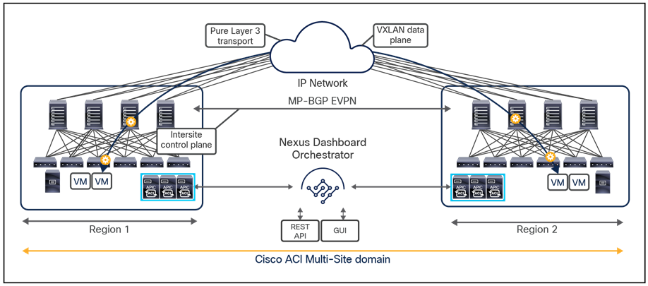
Cisco ACI Multi-Site architecture
Note:
This design is achieved by using the following functional components:
● Cisco Nexus Dashboard Orchestrator (NDO): This component is the intersite policy manager. It provides single-pane management, enabling you to monitor the health-score state for all the interconnected sites. It also allows you to define, in a centralized place, all the intersite policies that can then be pushed to the different APIC domains for rendering them on the physical switches building those fabrics. It thus provides a high degree of control over when and where to push those policies, hence allowing the change domain separation that uniquely characterizes the Cisco ACI Multi-Site architecture.
Prior to the Orchestrator Software Release 3.2(1), this component was named Multi-Site Orchestrator (MSO), whereas in newer releases it is supported only as an application running on the Cisco Nexus Dashboard (ND) compute platform, hence the new name Nexus Dashboard Orchestrator (NDO). However, in Cisco documentation you could indifferently find reference to “Multi-Site Orchestrator (MSO)”, “Nexus Dashboard Orchestrator” (NDO), or simply “Orchestrator service.” All these names refer to the same functional component of the Cisco Multi-Site architecture.
For more information about Cisco Nexus Dashboard Orchestrator, see the section “Cisco Nexus Dashboard Orchestrator.”
● Intersite control plane: Endpoint reachability information is exchanged across sites using a Multiprotocol-BGP (MP-BGP) Ethernet VPN (EVPN) control plane. This approach allows the exchange of MAC and IP address information for the endpoints that communicate across sites. MP-BGP EVPN sessions are established between the spine nodes deployed in separate fabrics that are managed by the same instance of Cisco Nexus Dashboard Orchestrator, as discussed in more detail in the section “Cisco ACI Multi-Site overlay control plane.”
● Intersite data plane: All communication (Layer 2 or Layer 3) between endpoints connected to different sites is achieved by establishing site-to-site Virtual Extensible LAN (VXLAN) tunnels across a generic IP network that interconnects the various sites. As discussed in the section “Intersite connectivity deployment considerations”, this IP network has no specific functional requirements other than the capability to support routing and increased Maximum Transmission Unit (MTU) size (given the overhead from the VXLAN encapsulation).
Note: Starting from Nexus Dashboard Orchestrator Software Release 4.0(1), a new deployment model is supported, allowing you to deploy NDO to manage up to 100 “autonomous fabrics.” In that specific use case, there is no VXLAN EVPN intersite connectivity between the fabrics that are part of the Multi-Site domain, and the Orchestrator essentially becomes a single pane of glass from where to provision configurations to all those sites. Layer-3-only communication is possible between the fabrics, leveraging the L3Out data path. For more information on the deployment of NDO with “autonomous fabrics,” please refer to the “Layer-3-only connectivity across sites” section.
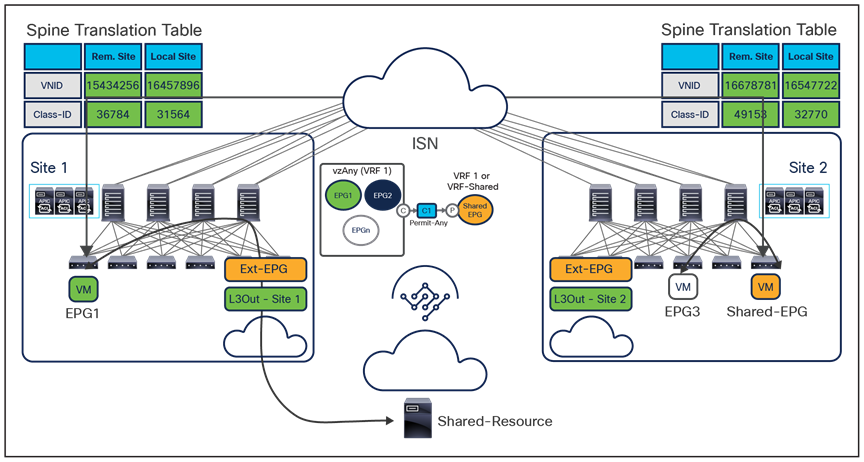
The use of site-to-site VXLAN encapsulation greatly simplifies the configuration and functions required for the intersite IP network. It also allows network and policy information (metadata) to be carried across sites, as shown in Figure 6.
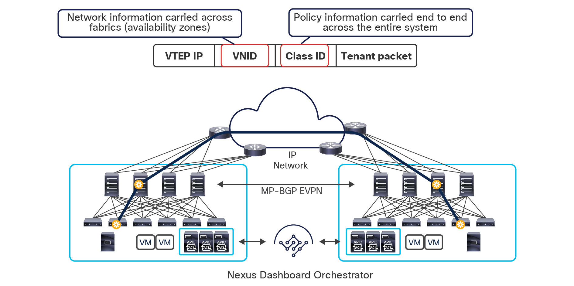
Carrying network and policy information across sites
The VXLAN Network Identifier (VNID) identifies the bridge domain (BD) (for Layer 2 communication) or the Virtual Routing and Forwarding (VRF) instance (for Layer 3 traffic) of the endpoint sourcing the traffic (for intra-VRF communication). The class ID is the unique identifier of the source Endpoint Group (EPG). However, these values are locally significant within a fabric. Because a completely separate and independent APIC domain and fabric are deployed at the destination site, a translation function (also referred to as “name-space normalization”) must be applied before the traffic is forwarded inside the receiving site, to help ensure that locally significant values identifying that same source EPG, bridge domain, and VRF instance are used.
To better understand the need for this name-space normalization function, it is important to clarify what happens when a specific contract is defined between two EPGs deployed in separate sites in order to allow intersite communications between endpoints that are part of those EPGs. As shown in Figure 7, when the desired configuration (intent) is defined in Cisco Nexus Dashboard Orchestrator and then pushed to the different APIC domains, specific copies of EPGs, named shadow EPGs, are automatically created in each APIC domain. This ensures that the whole configuration centrally defined in NDO can be locally instantiated in each site and the security policy properly enforced, even when each EPG is only locally defined and not stretched across sites (specific VNIDs and class IDs are assigned to the shadow objects in each APIC domain).
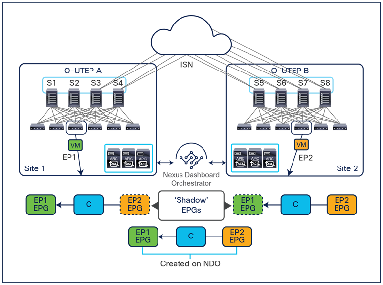
In the example above, the yellow EP2 EPG (and its associated BD) is created as a “shadow” EPG in APIC domain 1, whereas the green EP1 EPG (and its associated BD) is a “shadow” EPG in APIC domain 2. Up to Cisco ACI Release 5.0(1), the shadow EPGs and BDs are not easily distinguishable in the APIC GUI, so it is quite important to be aware of their existence and role.
Since both APIC domains are completely independent from each other, it is logical to expect that different VNID and class-ID values would be assigned to a given EPG (the “real” and the “shadow” copy) across sites. This implies that a translation of those values is required on the spines receiving data-plane traffic from a remote site before injecting the traffic into the local site, as highlighted in Figure 8, below.
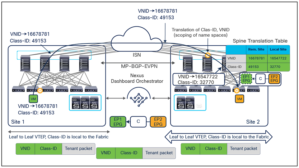
Name-space translation function on the receiving spine
When the policy is created on Cisco Nexus Dashboard Orchestrator stating that “EP1 EPG” must communicate with “EP2 EPG,” the Nexus Dashboard Orchestrator receives from each APIC controller the specific identifiers (pcTag, L2VNI, L3VNI) assigned to the local and shadow objects, and instructs the APIC controllers to program proper translation rules in the local spines. The end result is that the configured policy can then correctly be applied on the leaf node before sending the traffic to the destination endpoint. Additionally, the creation of a contract between EPGs locally deployed in separate sites usually results also in the configuration of the BD subnets associated to the EPGs on the leaf nodes of remote sites (in order to enable the proxy-path via the local spine nodes). More details about this can be found in the “Cisco ACI Multi-Site overlay data plane” section.
Note: The example in Figure 8 shows the policy being applied on the leaf node in the receiving site. This is normally the case until the leaf node in the source site learns via the data-plane the location information of the remote endpoint. From that moment on, the policy can be applied directly on the ingress leaf. The use of service-graph with Policy-Based Redirection (PBR) is a specific case where this may not be always the case, as discussed in more detail in the “Network services integration” section.
This name-space translation function should be performed at line rate to avoid negatively affecting the performance of intersite communication. To achieve this, you must use specific hardware for the spine nodes deployed in the Cisco ACI Multi-Site architecture: only the Cisco Nexus EX platform (and newer) generation of spine switches are supported in a Multi-Site deployment. Note that first-generation spine switches can coexist with the new spine-switch models, as long as the latter are the only ones connected to the external IP network and used for intersite communication, as shown in Figure 9.
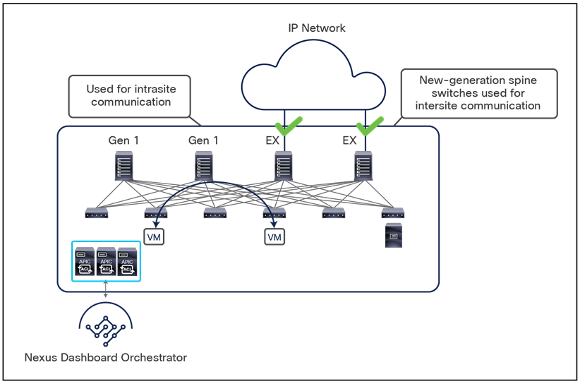
Coexistence of first-generation spine switches with EX-platform (and newer) spine switches
The specific coexistence scenario displayed in Figure 9 also shows that not every deployed spine needs to be connected to the external Layer 3 domain. You determine the number of spines and links used to connect to the external IP network based on the specific hardware available and your desired level of resiliency and throughput.
Note: For specific non modular spine models, as the 9332C and 9364C platforms, it is also possible to use the native 10G interfaces (SFP based) to connect to Inter-Site Network (ISN) devices.
The introduction of the Cisco ACI Multi-Site architecture also allows you to scale up the total number of leaf and spine nodes deployed across the interconnected fabrics, as well as the total number of endpoints. This capability is one of the main points of differentiation between Cisco ACI Multi-Site and Multi-Pod designs, because the latter option is still bound by the scalability restrictions of a single fabric design.
Note: When planning a Cisco ACI deployment, you always should refer to the scalability guides available at Cisco.com. See, for example, the following link for the scalability guide valid for the Cisco ACI Release 4.0(1): https://www.cisco.com/c/en/us/td/docs/switches/datacenter/aci/apic/sw/4-x/verified-scalability/Cisco-ACI-Verified-Scalability-Guide-401.html.
The translation table entries on the spine nodes are always populated when an EPG is stretched across sites; this is required to allow intra-EPG communication that is permitted by default. If instead there is a requirement to establish intersite communication between endpoints that are part of EPGs locally defined in separate sites, the definition of a contract between the EPGs is required to trigger the proper population of those translation tables (this is the example shown in figures 7 and 8, above). It is therefore mandatory to define the contract and the EPGs and apply the contract between them directly on NDO when there is a requirement to establish intersite communication via the intersite network (VXLAN data-path). Notice that this contract could be very simple (the equivalent of a “permit all”) and could be applied between all the different EPG pairs if the goal is to allow any-to-any communication.
Support for two additional functionalities – preferred group and vzAny – has been introduced on Nexus Dashboard Orchestrator to simplify the definition of policies between EPGs and allow the proper programming of the translation tables on the spines for intersite connectivity. Those functionalities will be discussed in the following two sections.
Note: The content of the translation tables can be verified by connecting to the spine nodes and issuing the CLI command “show dcimgr repo {eteps | sclass-maps | vnid-maps}”.
Cisco ACI Multi-Site and preferred group support
Cisco ACI Release 4.0(2) introduces support for EPG preferred groups with Cisco ACI Multi-Site. The preferred group construct is enabled at the VRF level and allows grouping together of all (or a subset of) the EPGs defined in that VRF. As shown in Figure 10, EPGs that are part of the preferred group can communicate with each other without requiring the creation of a contract. EPGs that are excluded from the preferred group still require the definition of a contract to communicate between them and with any of the EPGs included in the preferred group.
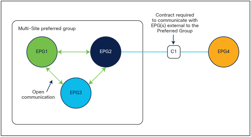
Note: A contract must be applied to all the individual EPGs part of the preferred group in order to communicate with EPGs external to the preferred group.
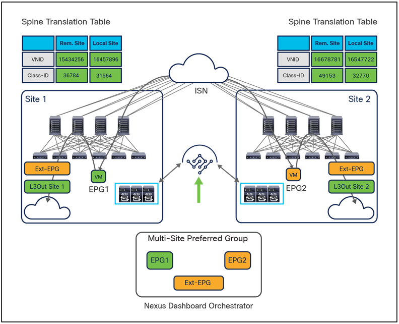
For the specific Cisco ACI Multi-Site scenario, the inclusion of EPGs as part of the preferred group must be done directly on NDO and causes the automatic creation of the proper translation entries on the spines to enable intersite communication between endpoints that are part of those EPGs and also north-south communication with the external network domain (Figure 11).
Use of preferred groups to enable north-south and east-west communication
As such, it is important to consider the overall scalability figures for the number of EPGs supported in a preferred group. As previously mentioned, this information is available on the Validates Scalability Guide available on the Cisco.com website.
One other important consideration is for the configuration of a preferred group for an external EPG (Ext-EPG) associated to an L3Out. When doing this, it is not possible to configure on an Ext-EPG the prefix 0.0.0.0/0 for classification purposes. This is because when traffic is received on an L3Out and classified based on such a prefix, the Class-ID of the VRF is assigned to the incoming packets and not the specific Class-ID of the Ext-EPG. As a consequence, communication with the other EPGs that are part of the preferred group for that VRF would not be allowed, since no security rule has been created to allow traffic from the VRF Class-ID to the specific EPG Class-IDs. As a workaround, it is instead possible to create for classification two separate prefixes (0.0.0.0/1 and 128.0.0.0/1), allowing you to cover the whole address space.
Finally, as of release 3.4(1) of the Orchestrator and 5.2(1) of the APIC, it is not possible to use preferred-group to enable Intersite L3Out connectivity. For more information about Intersite L3Out, refer to the “Introducing the Intersite L3Out Functionality (ACI 4.2(1) Release and onward)” section.
Cisco ACI Multi-Site and vzAny support
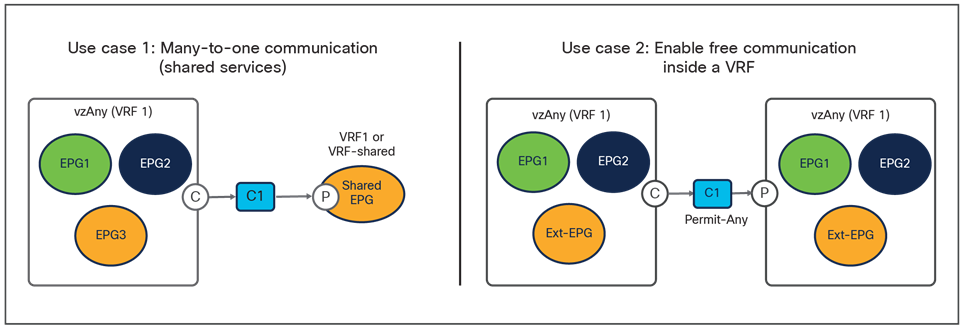
Cisco Multi-Site Orchestrator Release 2.2(4) introduces support in Multi-Site for the vzAny functionality. vzAny is a logical construct representing all the EPGs (internal and external) that are part of a given VRF. Being able to represent all those items with a single object simplifies the deployment of the two main cases shown in Figure 12.
Main use cases supported with vzAny
● The first use case consists in applying a “many-to-one” security policy between all the EPGs that are part of a given VRF and a shared resource that can be part of the same VRF or in a separate VRF. Instead of having to apply the contract between each individual EPG and the shared EPG, it is possible to configure “vzAny” as consumer of the contract provided by the shared EPG. Notice that doing so only ensures the application of the security policy between each EPG and the shared EPG, but not between EPGs that are part of the same VRF.
The exposure of the vzAny construct on the Orchestrator from Release 2.2(4) ensures that this “many-to-one” security policy enforcement paradigm can be deployed independently from the fact that the endpoints are part of the same ACI fabric or deployed across different sites, allowing also access to a shared resource in the external network domain (Figure 13).
Many-to-one communication across sites and with the external network
● If instead the goal is to open up communication between all the EPGs in the same VRF (an alternative configuration option to the use of Preferred Group), it is possible to configure vzAny to consume and provide a single contract defined with a “permit any” filter rule. Functionally, this allows you to achieve the same goal as the “VRF unenforced” option (not supported on NDO) removing the security policy from the equation and allowing you to use the ACI Multi-Site deployment only for network connectivity. As highlighted in Figure 14, this configuration option allows you to establish both east-west and north-south communication and results in the proper programming of the required translation entries in the spines.
Establishment of any-to-any intra-VRF communication
The use of vzAny in this scenario not only simplifies the configuration, removing the need for the creation of full mesh contracts between the EPGs, but also drastically reduces the TCAM utilization.
It is important to point out that the only requirement to support vzAny in a Multi-Site architecture is to run Cisco Multi-Site Orchestrator Release 2.2(4) (or newest NDO versions), and there is no dependency on the specific ACI SW versions deployed in the different fabrics that are part of the same Multi-Site domain. More considerations about dependencies between NDO and APIC SW releases can be found in the “Inter-version support (Cisco Multi-Site Orchestrator Release 2.2(1) and beyond)” section.
Also, as of Cisco ACI Release 6.0(4c) or later, and Cisco Nexus Dashboard Orchestrator (NDO) Release 4.2(3e) it is supported also associating a service graph to the contract used by vzAny (for both many-to-one and any-to-any use cases). For more information about this, please refer to the white paper below: https://www.cisco.com/c/en/us/solutions/collateral/data-center-virtualization/application-centric-infrastructure/white-paper-c11-743107.html
Cisco Nexus Dashboard Orchestrator
Cisco Nexus Dashboard Orchestrator (NDO) is the product responsible for provisioning, health monitoring, and managing the full lifecycle of Cisco ACI networking, fabric, and tenant policies across Cisco ACI sites around the world. It essentially represents the single source of truth for all the tenant policies required to establish intersite (that is, east-west) communication between endpoints deployed in separate ACI fabrics.
In its latest implementation, Cisco Nexus Dashboard Orchestrator is enabled as a service running on top of a Cisco compute cluster, named Nexus Dashboard. In previous implementations, the product was named “Cisco Multi-Site Orchestrator (MSO)”, so in the rest of this document you may still find references of the term “MSO,” especially when talking about functionalities that were originally introduced in that previous type of Orchestrator. For more details on the previous implementations of the Multi-Site Orchestrator, please refer to Appendix B.
Cisco Nexus Dashboard Orchestrator provides several main functions. It is worth noticing that the creation and management of user profiles and RBAC rules, together with the process of site onboarding, have been taken out of the Orchestrator and moved to the Nexus Dashboard compute platforms, because they represent services common to all the different applications that can be run on the ND compute cluster.
The following are the specific functionalities still offered by NDO:
● Use the health dashboard to monitor the health, faults, and logs of intersite policies for all the Cisco ACI fabrics that are part of the Cisco Multi-Site domain. The health-score information is retrieved from each APIC domain and presented in a unified way, as shown in Figure 15.
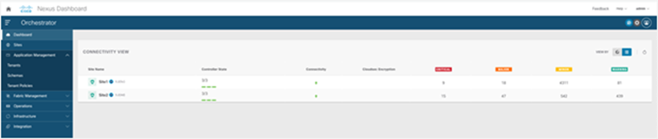
Cisco Nexus Dashboard Orchestrator dashboard
● Provision day-0 infrastructure to allow the spine switches at all Cisco ACI sites to peer with the Inter-Site Network (ISN) devices directly connected. Once the peering with the ISN is completed for each fabric part of the Multi-Site domain, the MP-BGP EVPN configuration automatically provided by NDO on all the spines ensures that they can connect with each other. This allows the system to establish MP-BGP EVPN control-plane reachability and exchange endpoint host information (MAC and IPv4/IPv6 addresses) across sites.
● Create new tenants and deploy them in all the connected sites (or a subset of them).
● Define application templates. Each application template can be associated with and pushed to a specific set of fabrics, as shown in Figure 16.
Note: One or more templates can be grouped together as part of a schema, which can be considered as a “container” of policies. However, the association of policies to a given tenant is always done at the template level (not at the schema level).
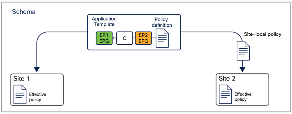
This feature is one of the most important that the Cisco Nexus Dashboard Orchestrator offers, together with the capability to define and provision scoped policies for change management. When you define intersite policies, Cisco Nexus Dashboard Orchestrator also properly programs the required name-space translation rules on the Multi-Site-capable spine switches across sites. As mentioned in the previous section, every intersite communication requires the creation of translation entries on the spine nodes of each fabric part of the Multi-Site domain. This happens only when the policy to allow intersite communication is defined on the Nexus Dashboard Orchestrator and then pushed to the different APIC cluster managing the fabrics. As a consequence, the best-practice recommendation is to manage the configuration of all the tenant objects (EPGs, BDs, etc.) directly on NDO, independently from the fact that those objects are stretched across multiple sites or locally defined in a specific site. For more information on how to deploy NDO schemas and application templates, please refer to the “Deploying NDO schemas and templates” section of this paper.
● From Software Release 4.0(1), other types of templates have been added to NDO (in addition to the Application templates mentioned above), allowing customers to provision specific template policies (tenant policies templates), fabric policies (fabric policies and fabric resource policies templates) and SPAN monitoring policies (monitoring policies templates). For more information on these new types of templates, please refer to the “Autonomous application templates (NDO Release 4.0(1))” section of this paper.
◦ Import policies from an already deployed Cisco ACI fabric (a brownfield deployment) and stretch them to another, newly deployed, site (a greenfield deployment). For more information, see the section “Brownfield integration scenarios.”
The Cisco Nexus Dashboard Orchestrator design is based on a microservices architecture in which the NDO services are deployed across Nexus Dashboard clustered nodes working together in an active/active fashion. The Cisco Nexus Dashboard Orchestrator services must communicate with the APIC nodes deployed in different sites. The communication between NDO and the APIC clusters can be established to the out-of-band (OOB) interface, the Inband (IB) interface, or both (more specific deployment information can be found in the “Cisco Nexus Dashboard deployment considerations” section). The Orchestrator also provides northbound access through representational state transfer (REST) APIs or the GUI (HTTPS), which allows you to manage the full lifecycle of networking and tenant policies that need to be deployed across sites (Figure 17).
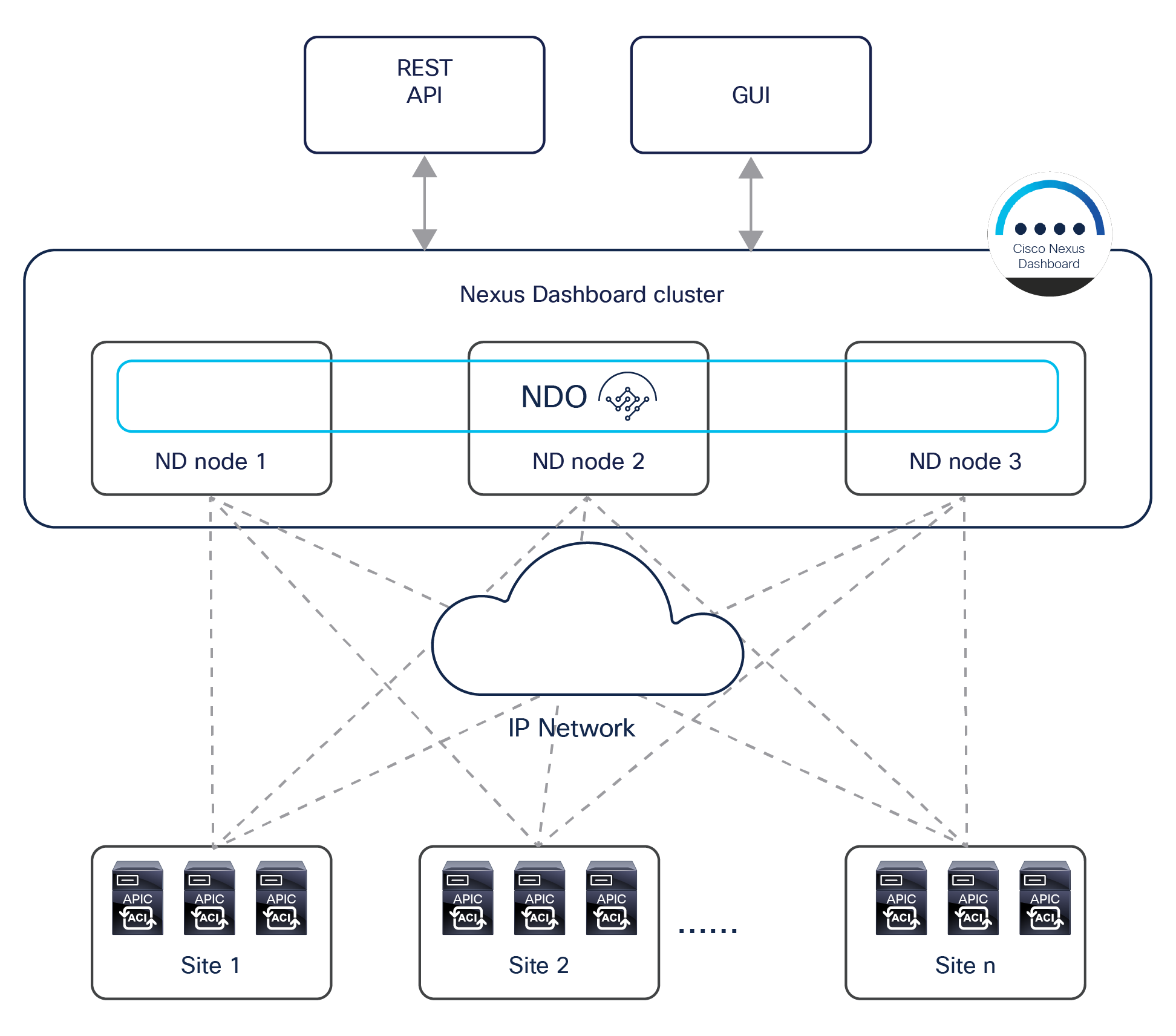
Cisco Nexus Dashboard Orchestrator running on Nexus Dashboard cluster
Security hardening is built into the Cisco Nexus Dashboard Orchestrator cluster. Note that the Cisco Nexus Dashboard Orchestrator cluster design has passed all leading industry benchmark vulnerability tests, such as Nessus, WhiteHat, Chaos Corona, and Norad resulting in no security vulnerabilities discovered.
In addition, all traffic between Orchestrator services running on different physical (or virtual) nodes is always secured. For NDO services running on top of different Nexus Dashboard cluster nodes, the encryption of traffic is handled by each specific service. For example, TLS is used for distributing the information in the Mongo DB, and connections to APIC are through HTTPS; Kafka also uses TLS. Hence, the Orchestrator services can be deployed securely over whatever network infrastructure is available to interconnect them.
Typical use cases for Cisco Nexus Dashboard Orchestrator
As previously discussed in the introduction, there are two popular use cases for the deployment of the Cisco ACI Multi-Site architecture managed by the Cisco Nexus Dashboard Orchestrator:
● Centralized (local) data center deployments, which require the creation of separate fabrics in the same DC location for scalability or fault domain isolation requirements
● Geographically distributed data centers across cities, countries, or continents, in which each data center is a treated as a “region” and requires a single pane of glass for provisioning, monitoring, and management to deploy stretched policies across regions
The following two sections provide more details about these deployment models. As will be clarified in a following section, it is also possible to deploy the ND cluster hosting the Orchestrator in the public cloud (that is, in a specific AWS or Microsoft Azure region) to manage from the cloud all of the ACI fabrics that are part of the Multi-Site domain. This approach can be applied to both of the use cases that are discussed below.
Cisco ACI Multi-Site deployment in a local data center for high leaf-node scale
The centralized deployment use case is popular in the financial and government sectors or with large service providers. In these scenarios, a Cisco ACI Multi-Site design is deployed in a building or a local campus with an ultra-high port count for bare-metal server, virtual machine, or container connectivity. A high number of leaf nodes are deployed across separate Cisco ACI fabrics to scale out the deployment and yet limit the scope of the failure domain and manage everything through a single pane of glass.
In the example shown in Figure 18, four Cisco ACI fabrics are deployed in one hall in four rooms, with each Cisco ACI fabric consisting of up to 500 leaf switches (when deploying a Multi-Pod fabric). The Cisco Nexus Dashboard Orchestrator service is deployed on top of a Nexus Dashboard cluster (three virtual machines in this example, but they could also be three physical nodes). Each ND virtual node can be deployed on its own separate hypervisor (ESXi or KVM) so that there is no single point of failure. All tenant policies can be stretched across all four Cisco ACI sites through the Cisco Nexus Dashboard Orchestrator interface. An additional ND standby primary node can be deployed to replace a failed ND active primary node.
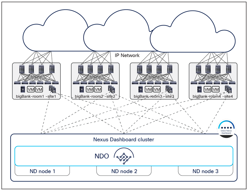
Cisco Nexus Dashboard cluster deployed within a data center
It is not required (and usually not recommended) to connect the bare-metal or virtual servers hosting the Orchestrator services directly to the ACI fabrics; this is to avoid specific ACI fabric connectivity issues that may prevent NDO from communicating with the APIC clusters. Since, as will be clarified in a following section, communication to the OOB, IB, or both interfaces of the APIC clusters is possible (depending on the specific NDO deployment model), one has full flexibility when it comes to where those clusters should be connected (for example, they could also be deployed outside the data center).
Cisco Nexus Dashboard Orchestrator deployment for data centers interconnected over WAN
The WAN use case is common among enterprises and service providers. In this scenario, geographically separated data centers are interconnected across cities in different countries or continents.
In the example shown in Figure 19, three Cisco ACI fabrics are deployed—in Rome, Milan, and New York—and all of them are managed from the Cisco Nexus Dashboard Orchestrator service running on the virtual (or physical) ND cluster stretched between Rome and Milan. An interesting point to note is that the New York site can be managed remotely by the NDO running on the Nexus Dashboard cluster deployed in Italy (due to the support for up to 500 msec RTT latency between an ND node and the APIC controller cluster it manages).
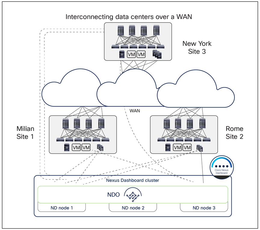
Cisco Nexus Dashboard cluster deployed across data centers interconnected over WAN
As a best practice, you should always deploy the Nexus Dashboard nodes hosting the Orchestrator as part of the same geographical region (United States, Europe, Asia, etc.) even when managing Cisco ACI fabrics that span the world. This is because of the 50 msec RTT latency supported for communication between the ND nodes part of the same ND cluster.
A stable data-plane connection must exist between the Cisco Nexus Dashboard nodes that are part of the same cluster when they are deployed over a WAN. The nodes in a Cisco Nexus Dashboard cluster communicate with each other over a TCP connection, so if any drops occur in the WAN, dropped packets will be retransmitted. Each ND cluster node is assigned a unique IP address; there is no requirement for those IP addresses to be part of the same IP subnet, as communication between the nodes can be routed.
The recommended connection bandwidth between nodes in a Cisco Nexus Dashboard Orchestrator cluster is from 300 Mbps to 1 Gbps. These numbers are based on internal stress testing while adding very large configurations and deleting them at high frequency.
Cisco Nexus Dashboard deployment considerations
The Orchestrator (NDO) is deployed as an application running on a cluster of compute resources represented by the Cisco Nexus Dashboard (ND). The first release 2.0(1) of Nexus Dashboard only supported a cluster of three physical ND compute nodes. From Nexus Dashboard release 2.0(2) onward, it is available as virtual form factors to be deployed on premises or in a public cloud (Figure 20).
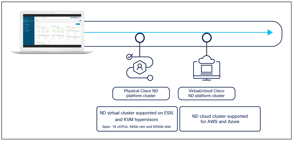
Nexus Dashboard cluster form factors supporting NDO
Note: To “mix and match” those form factors in the same cluster is not supported; only homogeneous deployment models are supported (that is, all physical nodes, all virtual nodes deployed on premises on the same hypervisor flavor, and all virtual nodes deployed in the cloud in the same cloud-service provider).
There are two differences when running NDO as a service on Nexus Dashboard when compared with the previous MSO deployment models described in Appendix B:
● The maximum latency between an ND node and the APIC cluster is reduced to 500 msec RTT (instead of the 1 sec RTT value previously supported with MSO).
● The maximum RTT latency supported for communication between the ND nodes part of the same ND cluster is 50 msec (instead of the 150 msec RTT value previously supported with MSO).
● The ND nodes can communicate with the APIC controllers using their OOB address, IB address, or both (whereas only OOB connectivity was supported with the previous MSO options).
Some important considerations are required for this last specific point. Each Nexus Dashboard compute node, independently from its form factor, has two types of interfaces: a management interface and a data interface (Figure 21).
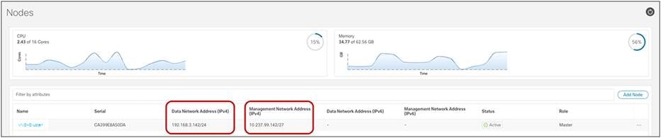
Nexus Dashboard compute node interfaces
Note: The figure above is for a single-node virtual ND cluster used for lab purposes. In real-life ND deployments, there would be 3 nodes part of the same cluster, each with its own interface.
A different routing table is associated to each of these interfaces, and a default route is added to each table pointing to the next-hop device. You can view the routing tables associated to the two interfaces by leveraging the commands below (after connecting in SSH to a Nexus Dashboard node as “rescue-user”):
Management Interface (bond1br)
rescue-user@vND-Cluster:~$ ip route show
default via 10.237.99.129 dev bond1br
10.237.99.128/27 dev bond1br proto kernel scope link src 10.237.99.142
100.80.0.0/16 dev bond0br scope link
169.254.0.0/25 dev k8br1 proto kernel scope link src 169.254.0.44
169.254.0.0/16 dev bond0br scope link metric 1006
169.254.0.0/16 dev bond1br scope link metric 1009
172.17.0.0/16 dev k8br0 proto kernel scope link src 172.17.222.0
192.168.3.0/24 dev bond0br proto kernel scope link src 192.168.3.142
Data Interface (bond0br)
rescue-user@vND-Cluster:~$ ip route show table 100
default via 192.168.3.150 dev bond0br
10.237.99.128/27 dev bond1br scope link
172.17.0.0/16 dev k8br0 scope link
192.168.3.0/24 dev bond0br scope link
For deciding how each ND cluster node should be connected to the network infrastructure, it is critical to understand that different functions and services running on ND have been designed to leverage (by default) the reachability information contained in one of the two routing tables described to communicate with various external services. This specific ND implementation leads to the following considerations:
For example, when ND tries to connect to an NTP server or to a proxy server, the lookup to reach that destination is done in the first routing table. On the other side, when trying to perform the onboarding of APIC controllers on ND, either by specifying the APIC's OOB or IB IP address, the lookup to reach that destination is done in the second routing table.
● The ND Management interface is dedicated to the management of the ND cluster, since its associated routing table is used by ND for connecting to NTP and DC proxy servers, Cisco Intersight clusters, and DNS servers, to provide UI access to ND (and ND Apps) and to perform firmware upgrades for ND and the applications running on it. Assuming all the services mentioned above are deployed in IP subnets different from the one assigned to the ND Management interface, the default route defined in that routing table would be used to communicate with all of them (in the example above, pointing to the next-hop device 10.237.99.129).
● The ND Data interface is used for to bring up the ND cluster (node-to-node communication) and by specific services (NDO, NDI, NDFC, etc.) running on ND for communication to controllers and switches. If the controllers and the switches are part of any IP subnet other than the one assigned to the ND Data interfaces, the default route in the routing table of the ND Data interface would be used to communicate with those devices (in the example above, pointing to the next-hop device 192.168.3.150).
● The default behavior described above could be changed by assigning to the ND Management or ND Data interface the same IP subnet of the external services and devices ND needs to communicate with. For example, if the ND Management interface was deployed in the same IP subnet of the APIC controllers, the entry 10.237.99.128/27 associated to the second routing table in the example above would ensure that the management interface would always be used to connect to the APICs. Alternatively, it is also possible to force the use of a specific interface by adding static routes associated to that ND interface. For example, if the APIC were part of IP subnet 192.168.1.0/24, associating that static route to the ND Management interface would ensure that the 192.168.1.0/24 entry would be installed in the second routing table pointing to the ND Management interface.
◦ Despite the flexibility offered by the ND platform in terms of connectivity (and described in the previous bullet point), the following are the best-practice recommendations when running NDO on the ND compute cluster:
◦ If running only the NDO service on the ND cluster, you can decide to assign both ND Management and Data interfaces to the same IP subnet. However, since this may create problems when enabling additional services (such as, for example, NDI) on the same cluster, it is strongly recommended to assign those two interfaces to different IP subnets.
◦ Also, it is strongly recommended to keep the default behavior of using the two ND interfaces for the specific default communications described in the first two points above. This implies assigning the ND Management and Data interfaces to IP subnets that are different from the ones used by the external entities ND needs to connect. The default routes in each routing table (and their associated interfaces) will hence be used depending on the specific communication that is required.
◦ The ND management interfaces of the node part of the same ND cluster can be part of the same IP subnet or be assigned to different IP subnets. The former is usually the case when the ND cluster is deployed in a specific DC location, the latter when the ND cluster is stretched across different DC locations. The same considerations apply for the ND data interfaces of the ND cluster nodes.
Figure 22 shows some typical deployment scenarios for a Nexus Dashboard cluster with NDO running on top.
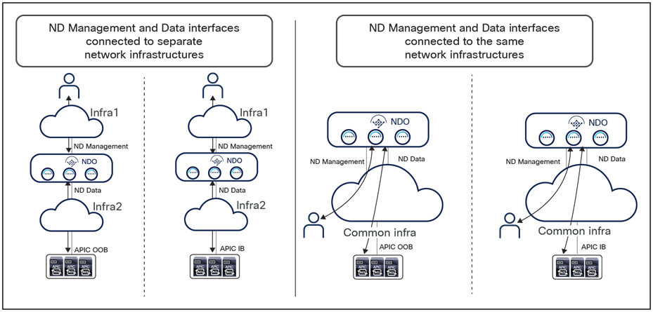
Nexus Dashboard compute node interfaces
The two scenarios on the left show the ND Management and Data interfaces being connected to separate network infrastructures. This makes clearer the dedicating of each interface to specific connectivity duties that was described above.
The two use cases on the right show, on the contrary, the use of a common network infrastructure to connect both ND Management and Data interfaces. In such scenarios, it would probably be very common to use different VRFs inside that network infrastructure to keep isolated the different types of required communications.
Note: For all of the use cases shown in Figure 22, when running only NDO on the Nexus Dashboard cluster, it is fully supported to establish connectivity with the APIC out-of-band (OOB) or inband (IB) interfaces, or both. The onboarding on Nexus Dashboard of a site (for example, the onboarding of the APIC managing that ACI fabric) can be done by specifying one of the IP addresses (OOB or IB) of one of the APIC nodes. Assuming ND can connect to the specified address (using the data interface when following the best-practice recommendations previously described), the IP addresses for all the other APIC nodes that are part of the same cluster will also be automatically discovered.
For more information on Cisco Nexus Dashboard and its capabilities of hosting applications, please refer to the documentation available at the links below: https://www.cisco.com/c/en/us/support/data-center-analytics/nexus-dashboard/products-installation-guides-list.html
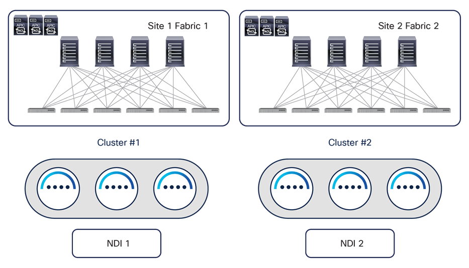
While a physical Nexus Dashboard compute cluster can host multiple applications and services, it is currently not possible to install the services associated to a single instance of NDO across separate Nexus Dashboard clusters, but only across the nodes of the same Nexus Dashboard cluster. This brings some interesting considerations for customers who are interested in leveraging both Nexus Dashboard Insights (NDI) and Nexus Dashboard Orchestrator services. While NDI deployment considerations are out of the scope for this paper, a basic rule of thumb is always not to spread an ND cluster hosting NDI across geographically separated locations (mostly because of the telemetry data ingestion requirements of NDI). This means that, for example, for a two-site deployment scenario, a separate physical ND cluster hosting NDI should be deployed in each DC location, as shown in Figure 23.
Typical NDI deployment for geographically dispersed data centers
When NDO needs also to be deployed in such scenarios, the restriction that currently a single NDO instance cannot be deployed across different ND compute clusters implies that a couple of different NDO deployment options are possible:
1. Deploy the Orchestrator service on a dedicated ND cluster (usually a virtual one) that can be spread across DC locations. As shown in Figure 24, in this recommended deployment model a vND cluster dedicated to NDO can be built using three virtual machines (ND primary nodes) hosted on premises and deployed in different sites. A fourth virtual ND primary node can be deployed as a standby to be able to take over and replace any failed active primary node.
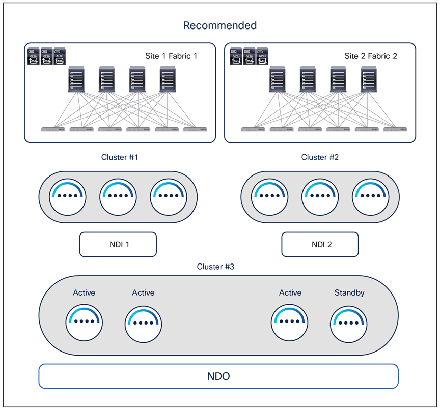
Recommended NDO and NDI deployment option for geographically dispersed data centers
The main advantages of running the Orchestrator service on a dedicated virtual ND cluster are:
● It represents the most flexible deployment option; the vND nodes hosting the Orchestrator service can be geographically dispersed up to 50 msec RTT of latency between them. This is ideal for scenarios where geographically dispersed fabrics are part of the same Multi-Site domain because it allows customers to deploy the vND nodes in those distributed data center locations (reducing the chances of losing multiple vND nodes at the same time). In the scenario shown in Figure 24, if DC1 were to completely fail, the vND standby node in DC2 could be promoted to active to bring the vND cluster in majority state and be able to provision policies to the remaining data center(s).
◦ It allows you to choose how to communicate with the APIC clusters, since both IB and/or OOB communication channels are possible between the vND nodes and the APICs for the Orchestration service (this may not be the case when other services are co-hosted on the ND cluster).
● You can run with just 3 vND primary nodes, independently from the number of sites and leaf nodes per site (based on the maximum supported values). An ND cluster hosting other services may require the deployment of additional “worker” nodes based on the site/leaf scalability requirements. For more information on the ND resources required to support different combinations of services, please refer to the Nexus Dashboard Capacity Planning tool at the link: https://www.cisco.com/c/dam/en/us/td/docs/dcn/tools/nd-sizing/index.html
◦ It allows you to run the Orchestrator services on a vND cluster that can be directly hosted in the AWS/Azure public clouds.
2. Install two separate NDO instances on the two ND clusters deployed in each data center and hosting the NDI instances, as shown in Figure 25.
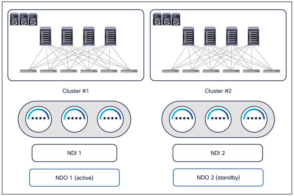
Alternative NDO and NDI deployment options for geographically dispersed data centers
One NDO instance is run as “active,” meaning it is used to manage all the fabrics part of the Multi-Site domain (in the example above, the two fabrics in DC1 and DC2). The second NDO instance is, instead, installed but not actively used (in a sort of “standby” mode). Periodic backups of NDO configurations can be taken on the NDO active instance and saved in a safe remote location. If, for whatever reason, the NDO service running on the ND Cluster 1 becomes unusable, it is possible to import the latest available backup into the second NDO instance running in DC2 and roll back to that configuration. At that point the second NDO instance becomes effectively “active” and can be used to start managing all the fabrics that are part of the Multi-Site domain.
Note: As of NDO release 4.4 (part of the ND unified image 3.2), the NDO roll back procedure mentioned above can be successfully completed only if all the APIC clusters of the fabrics part of Multi-Site domain are reachable. The specific DR use case where both the NDO cluster and the APIC cluster deployed in a given DC location are lost at the same time will be addressed in a future ND/NDO release.
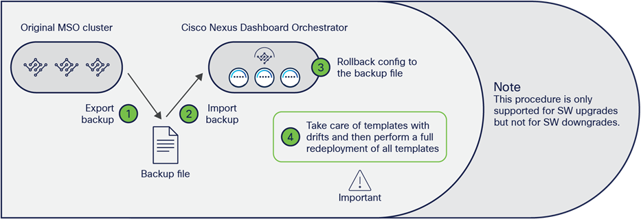
Another strong recommendation is always to deploy the latest version of the NDO software available. Upgrading between different NDO software releases is a quite straightforward process that can be handled directly from the Nexus Dashboard UI. Different considerations apply for what concerns the migration procedure between a VM-based or a CASE-based MSO cluster deployment and NDO. In that case, it is possible to perform the procedure shown in Figure 26.
Upgrading and/or migrating procedure between MSO and NDO
Note: The steps described below apply to migrating to any 3.x NDO release. Different considerations apply to migrating to NDO 4.0(1); please refer to the documents below for more information: https://www.cisco.com/c/en/us/td/docs/dcn/ndo/4x/deployment/cisco-nexus-dashboard-orchestrator-deployment-guide-401/ndo-deploy-migrate-40x.html
● Install the NDO application on a new ND cluster. You can connect the cluster to the network at this point, or alternatively after the step below, where the old MSO cluster is disconnected (this may be required if the same IP addresses need to be used for the old and new clusters).
● Create a backup configuration file on the old VM-based MSO cluster and download the file to a location from where it can be easily retrieved.
● Shut down (or simply disconnect) the old VM-based MSO cluster.
● Import the file into the new NDO application running on the ND cluster (after connecting it to the network, in case this was not already done in the initial step).
● Roll back the configuration of the new NDO application running on the ND cluster to the one contained in the configuration file just imported. This allows you to import both the NDO infrastructure configuration and tenant-specific policies in the new cluster.
Note: Since the onboarding of ACI sites is managed directly on the Nexus Dashboard, in order to be able to successfully roll back the NDO configuration, it is mandatory to ensure that the names assigned to the ACI fabrics onboarded on ND match the names of the ACI fabrics originally onboarded on the MSO cluster.
● Once the rollback of the configuration is completed, some of the templates may show some drift. A drift means that there is a discrepancy between the APIC and NDO configuration of one (or more) objects. A drift may appear after a configuration rollback between two Orchestrator releases that can manage different ACI objects (or objects’ properties). This is the case, for example, when migrating from MSO 2.2 to NDO 3.7, since NDO 3.7 can manage more objects than MSO 2.2. Therefore, once the rollback is completed, NDO 3.7 would assign default values to all the objects it manages but that were not previously managed by MSO 2.2. Those default values may be different from the actual values those objects have on the APICs managing the fabrics that are part of the Multi-Site domain; this would be, for example, the case if those values were changed directly on the APIC given that MSO 2.2 could not manage them. Those drifts can be resolved leveraging a drift-reconciliation workflow that has been introduced since NDO Software Release 3.4(1). For more information on that, please refer to the “NDO operational enhancements” section.
◦ Once all the drifts have been resolved, one last step is required when migrating to an NDO release before 3.8(1). This step consists in redeploying all the defined application templates; it is required to ensure the configuration information for all those templates is properly saved in the NDO database (since this database implements a new format in NDO compared to the format used in MSO). From NDO Release 3.8(1), this “redeployment” is instead automatically handled as part of the migration procedure, so the only thing you need to take care of after the rollback is to resolve configuration drifts (if present).
Note: For more information on this MSO-to-NDO migration procedure, please refer to the document at the link below: https://www.cisco.com/c/en/us/td/docs/dcn/ndo/3x/deployment/cisco-nexus-dashboard-orchestrator-deployment-guide-371/ndo-deploy-migrate-37x.html
Deploying NDO schemas and templates
Multi-Site application templates
The creation of tenant-specific policies (EPGs, BDs, VRFs, contracts, etc.) is always done in NDO within a given application template, because each template is always associated to one (and only one) tenant. Multiple application templates can then be grouped together inside a schema, which essentially represents a container of application templates.
Despite the fact that a schema is not directly associated to a specific tenant, it is a quite common, and also a best-practice, deployment option to group together inside a schema all of the application templates associated to a given tenant, in order to have an easy way to visualize and modify specific tenant policies from the NDO GUI.
Each defined application template must then be mapped to one (or more) sites that are part of the same Multi-Site domain.
Mapping application templates to ACI sites
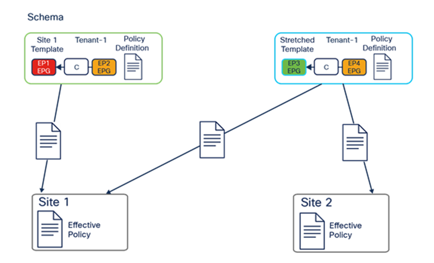
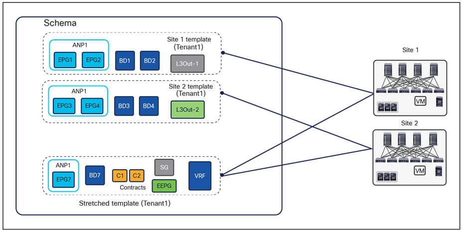
Figure 27 shows the creation of two application templates associated to the same Tenant-1:
● “Site 1 template” is mapped to the specific ACI site 1: This implies that all the specific tenant policies created in that application template can be pushed and deployed (that is, “rendered”) only to the APIC cluster managing that specific ACI fabric.
◦ “Stretched template” is mapped to both ACI sites 1 and 2: As a consequence, all the tenant policies thereby defined are deployed to both sites, leading to the creation of “stretched” objects (that is, objects that are rendered in multiple sites). As an example, and as it will be clarified in the “ACI Multi-Site use cases,” the use of a stretched application template is required to be able to extend a BD across sites.
Based on the current NDO implementation, an application template therefore represents the atomic unit of change for policies: this means that all the changes applied to that template are always pushed immediately to all the site(s) mapped to the template. Specific changes can be pushed only to a specific site when applied to an application template that is solely mapped to that site.
The organization of policy objects in application templates and schemas is quite flexible. In some cases, it may be handy to place network-specific objects (BDs, VRFs) and policy-specific objects (EPGs, contracts, etc.) in separate application templates or even schemas, under the assumption that policy-specific objects are modified more frequently than networking ones.
Figure 28 highlights how it can be possible to reference objects that are defined inside the same application template, across application templates that are part of the same schema or even across application templates contained in separate schemas. All those references can be created between application templates associated to the same tenant or even to separate tenants (as typically would be the case when defining network-specific objects in the “common” tenant).
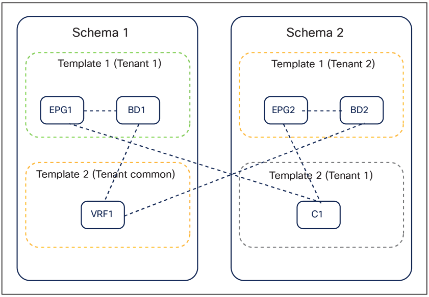
Referencing objects across application templates and across schemas
While technically it is possible to spread configuration objects for the same application tenant across multiple templates and schemas, it is strongly recommended consolidating all the application templates associated to the same tenant in a specific schema (the “tenant schema”), as shown in Figure 29.
Best practices to define application templates inside a schema with NDO 3.x releases
A dedicated application template is mapped 1:1 to each site in the Multi-Site domain; in addition, a stretched application template is mapped to all the sites. VRFs and contracts are typically defined in the stretched application template, as they normally must be available on all the sites. BDs/EPGs are defined either on the stretched application template or on the site-specific application templates, depending on whether they are local or extended across sites.
When following this approach, it is important to check the ACI Verified Scalability Guide (VSG) for the specific software release that is deployed, for the maximum number of application templates and overall objects that can be supported in a given schema. In large-scale deployments, it may be required to deploy templates associated to the same tenant across multiple schemas in order to stay within the validated and supported scalability boundaries for each schema.
The approach shown in Figure 29 represents the best-practice deployment model for any NDO 3.x software release. Beginning with Release 4.0(1), Nexus Dashboard Orchestrator will validate and enforce several best practices when it comes to application template design and deployment:
● All policy objects must be deployed in order according to their dependencies.
For example, when creating a bridge domain (BD), you must associate it with a VRF. In this case, the BD has a VRF dependency so the VRF must be deployed to the fabric before or together with the BD. If these two objects are defined in the same template, then the Orchestrator will ensure that during deployment, the VRF is created first and associate it with the bridge domain. However, if you define these two objects in separate templates and attempt to deploy the template with the BD first, the Orchestrator will return a validation error as the associated VRF is not yet deployed. In this case you must deploy the VRF template first, followed by the BD template.
● All policy objects must be undeployed in order according to their dependencies, or in other words in the opposite order in which they were deployed.
As a corollary to the point above, when you undeploy templates, you must not undeploy objects on which other objects depend. For example, it is not possible to undeploy a VRF before undeploying the BD with which the VRF is associated.
● No cyclical dependencies are allowed across multiple templates.
Consider a case of a VRF1 associated with a bridge domain BD1, which is in turn associated with EPG1. If you create VRF1 in template1 and deploy that template, then create BD1 in template2 and deploy that template, there will be no validation errors since the objects are deployed in the correct order.
However, if you then attempt to create EPG1 in template1, it will create a circular dependency between the two templates, so the Orchestrator will not allow you to save template1 with the newly added EPG.
The introduction of these additional rules and requirements has two main implications:
1. For greenfield configurations created directly on NDO 4.0(1), the best-practice recommendation previously shown in Figure 29 is slightly modified to the version show in Figure 30.
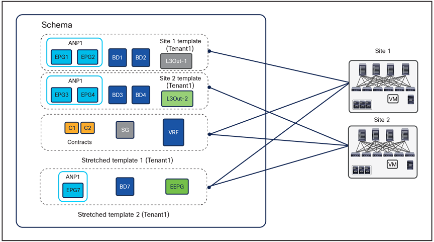
Best practices to define application templates inside a schema, beginning with NDO 4.x releases
The main difference is that two stretched templates are required with NDO 4.0(x) and later, to be able, for example, to define the VRF and the external EPG (referencing that VRF) in two separate templates and to avoid the creation of a cyclical dependency between those objects; this would cause an error when trying to deploy the single stretched template previously used.
Note: NDO release 4.1 introduces support for “L3Out Templates” that can be used to fully manage the provisioning of a Tenant L3Out directly from NDO. NDO release 4.2 introduces instead “Service Device” templates that can be used to define service nodes and PBR policies directly on NDO and consequently deploy the service graph functionality. As a consequence, when running NDO release post 4.2, it is likely that the L3Out and Service Graph objects are not going to be defined anymore as part of the Application templates shown in previous Figure 30.
2. Performing an upgrade to Release 4.0(1) or later from an earlier 3.x release requires an analysis of all existing templates and conversion of any template that does not satisfy the new requirements previously described. This is done automatically by the system during the migration process, and you will receive a detailed report of all the changes that must be applied to your existing templates to make them compliant with the new best practices. If starting with the best-practices deployment model shown in Figure 29, the system will automatically reorganize the objects to mimic the new best-practice deployment model shown in Figure 30.
Note: For more information on the specific procedure to follow to upgrade from NDO 3.x to NDO 4.x releases, please refer to the document at the link below: https://www.cisco.com/c/en/us/td/docs/dcn/ndo/4x/deployment/cisco-nexus-dashboard-orchestrator-deployment-guide-401/ndo-deploy-migrate-40x.html
To provide even more flexibility when organizing policy objects, Cisco Nexus Dashboard Orchestrator supports the migration of EPGs and BDs across application templates (in the same schema or even across schemas) that are associated to the same tenant. Typical use cases for this functionality are being able to start stretching across sites an EPG/BD pair originally defined locally in a site, and vice versa.
Autonomous application templates (NDO Release 4.0(1))
NDO Software Release 4.0(1) introduces a new type of application template, called an “autonomous template.” This type of application template allows you to provision the same objects (EPGs, BDs, VRFs, etc.) of a traditional application template (renamed “Multi-Site templates”); it can also be associated to a single site or to multiple sites. However, the fundamental difference between these two types of application templates is the fact that deploying an “autonomous template” to multiple sites does not result in the creation of “stretched” objects (and their associated translation entries, whose use will be discussed in a later section of this document).
As shown in Figure 31, the use case for the deployment of “autonomous application templates” is when there is a requirement to replicate the same configuration across multiple fabrics that are deployed and operated independently of each other (that is, there is no ISN infrastructure connecting the spines of the different ACI fabrics).
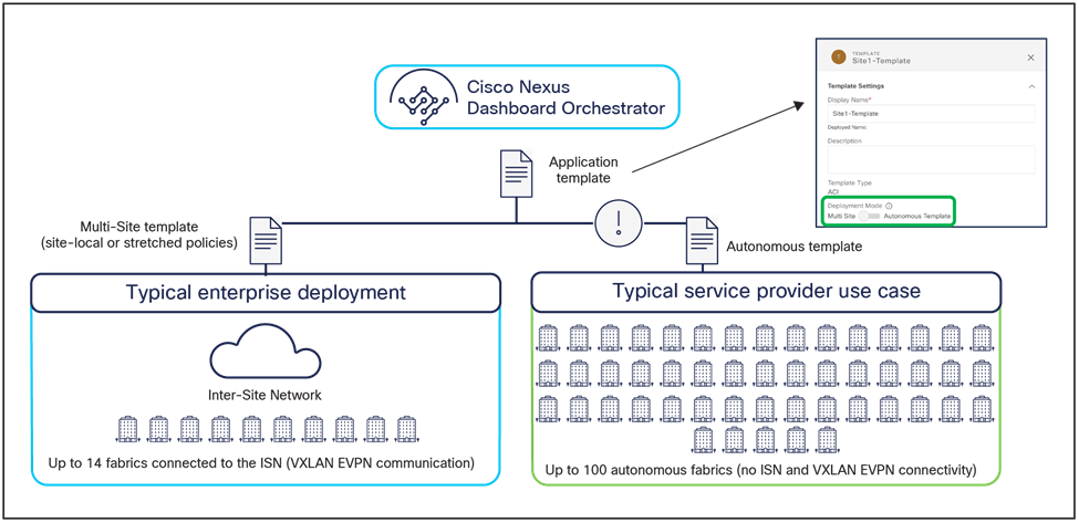
Multi-Site and autonomous application templates
It is important to reiterate how associating an autonomous template to multiple sites does not end up creating “stretched objects,” but, instead, creates independent objects that may simply share the same name. For example, if VRF1 is defined in an autonomous application template associated to sites 1 and 2, the same VRF1 object is going to be created on both APIC domains. However, from a functional perspective, they are two completely independent VRFs that can only be interconnected through the L3Out data-path. Similar considerations apply to the creation of EPGs with the same name, etc.
Given the considerations made above, it is important to follow some specific guidelines for deploying Multi-Site and autonomous application templates:
● A Multi-Site template must only be associated to multiple sites that are also “Multi-Site”–enabled. This implies that the “Multi-Site” knob associated to each site is turned on and the infrastructure configuration for each site has been fully provisioned to ensure connectivity to the Inter-Site Network (ISN). This is because, as already mentioned, the deployment of the Multi-Site template causes the provisioning of stretched objects that mandates VXLAN intersite communication through the ISN.
Note: Starting with NDO Release 4.0(3), the Orchestrator will enforce this guideline and prevent the association of a Multi-Site template to multiple “autonomous” sites.
● An autonomous template can also be associated to sites that are Multi-Site enabled (i.e. the corresponding “Multi-Site” flag is checked for those sites) and that are interconnected through the ISN. It is important to understand that no stretched objects are being created across sites when doing so.
New template types Introduced in NDO Release 4.0(1)
Starting from NDO Software Release 4.0(1), new template types have been introduced to expand the provisioning capabilities of the Nexus Dashboard Orchestrator. These new templates are shown in Figure 32 and briefly described below.
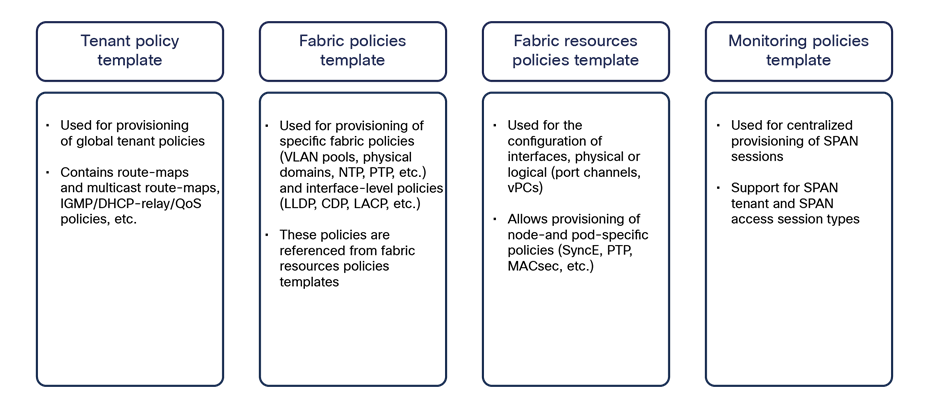
Template types introduced in NDO 4.0(1)
● Tenant policy template: This template is used to provision specific policies for a given tenant that can be used for different purposes. For example, route-maps to be used for tenant-routed multicast configurations or to control the routes advertised on SR-MPLS L3Outs, custom QoS policies, etc. Each defined tenant policy template can be associated to one or more sites, depending on whether the policies must be unique per site or can be commonly applied to a group of sites.
● Fabric policies template and fabric resources policies template: These two types of templates are examples of “fabric management” templates that can be used to provision fabric-specific policies (such as interfaces and interfaces’ properties, physical domains and associated VLAN pools, etc.). Before NDO 4.0(1), such configurations could only be provisioned independently at each specific APIC level. As is the case for tenant policy templates, those fabric management templates can also be associated to one or more sites, depending on whether the policies must be unique per site or can be commonly applied to a group of sites.
● Monitoring policies template: This type of template can be used to provision SPAN sessions for replicating traffic to be monitored toward an external collector. Two types of SPAN configurations are supported: tenant and access SPAN.
Note: Providing configuration details for those new templates is out of the scope for this paper. For more detailed provisioning information, please refer to the documents at the following links: TBD https://www.cisco.com/c/en/us/td/docs/dcn/ndo/4x/configuration/cisco-nexus-dashboard-orchestrator-configuration-guide-aci-401/ndo-configuration-aci-fabric-management-40x.html
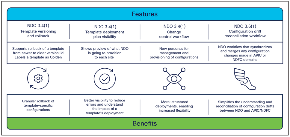
Different NDO software releases have introduced several critical enhancements to simplify and improve the operational aspects of the Cisco ACI Multi-Site architecture. Figure 33 highlights those template-level enhancements.
Note: Specific configuration information for all those functionalities can be found in the NDO configuration guide below: https://www.cisco.com/c/en/us/td/docs/dcn/ndo/3x/configuration/cisco-nexus-dashboard-orchestrator-configuration-guide-aci-371/ndo-configuration-aci-managing-schemas-37x.html?bookSearch=true
● Template versioning and rollback: In earlier releases of the Orchestrator, the only possibility to perform configuration backups and rollbacks was at the global-system level. While this functionality is quite useful and still available in the latest versions of the software, a more granular approach was required. Since the atomic unit of provisioning from NDO is the template (whatever type it is), this requirement led to the introduction of providing backups and rollback capabilities at the template level.
NDO can now keep track of different versions of a template (up to 20), set a specific version as “golden” (this is the version that will never be automatically deleted from the system), allow graphic display of detailed differences between the latest version of a template and any selected older version (see Figure 34), and roll back at any time the configuration of the template to any selected older version.
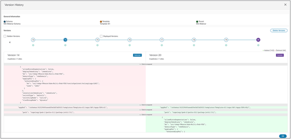
This latest functionality is particularly interesting as it provides a sort of “undo” functionality built into the system: if the deployment of a template at any given point in time causes any sort of functional or connectivity issue, it is possible to quickly roll back the configuration to an earlier deployment that was known to be working fine.
For more information and a live demonstration of template versioning and rollback, please refer to the link below: https://video.cisco.com/video/6277140235001
● Template deployment plan visibility: One of the main concerns customers adopting NDO always bring up is the fact they want to have better visibility into what configuration NDO is pushing and where (that is, to which APIC domains) when they deploy a specific template. Depending on the specific configuration created in a template, its deployment may in fact end up provisioning objects to sites different from the ones the template is associated to. This, for example, is the case when shadow objects are created to enable the VXLAN data-path between sites (the use of shadow objects will be discussed in detail later in this document). Template deployment plan visibility has been introduced to clearly display to the user, both in graphical and XML formats, what changes will be applied (and to which sites) as a result of the template’s deployment. This would allow the user to catch upfront any unexpected behavior (due to a misconfiguration or a bug in the system), halt the template’s deployment, and thus prevent a possible outage. Figure 35 shows the graphical and XML output of the template deployment plan.
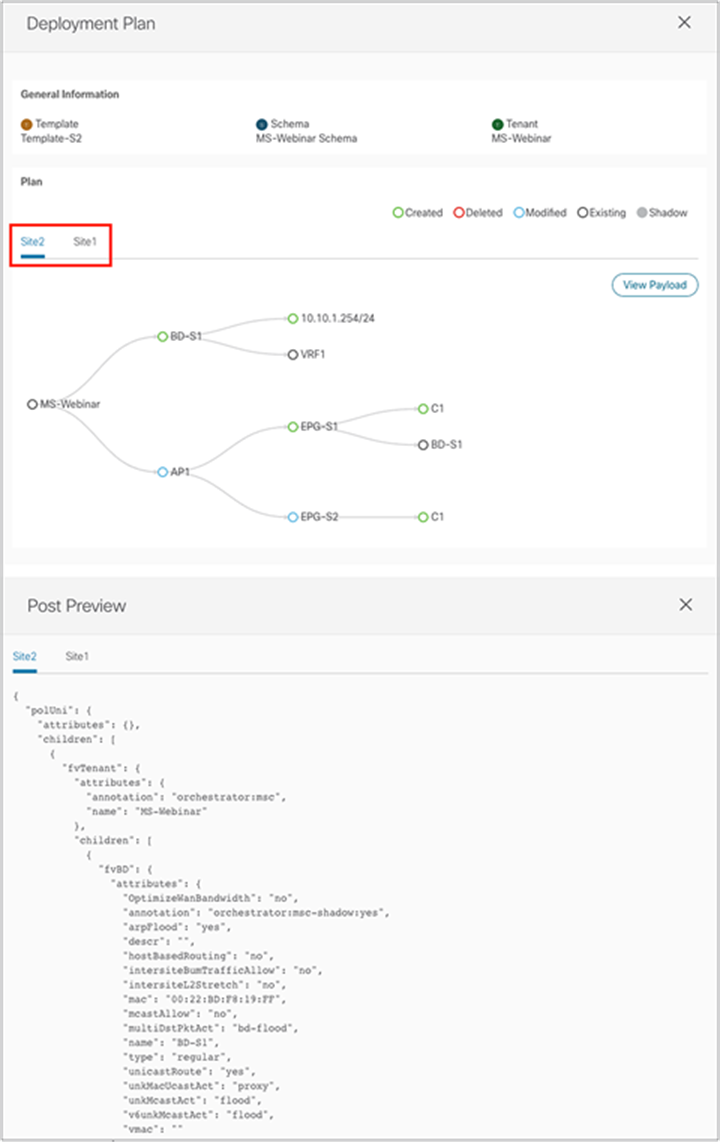
Graphical and XML views of a template deployment plan
For more information and a live demonstration of template deployment plan visibility, please refer to the link below: https://video.cisco.com/video/6277137504001
● Change control workflow: Different customers operate NDO in different ways. Very often, they require having different types of users perform different parts of a specific template’s configuration provisioning, and they may have specific and strict rules to adhere to before any change can be applied to the system. The change-control workflow has been introduced into NDO to provide a capability to define three different types of user’s roles:
◦ The designer, responsible to create or modify a template’s configuration
◦ The approver, whose tasks are to review and approve or deny the configuration changes proposed by the designer. Note that it is possible to require approval from multiple approvers before a template may be deployed. If the approver(s) reject the deployment of the template, a message is sent back to the designer explaining the reasons behind that rejection.
◦ The deployer, who is responsible for deploying the template. The deployer can also reject deployment of the template and send back a message to the designer, who can then take any needed corrective action.
The definition of the roles described above is flexible, and, depending on specific requirements, different roles can be combined. Also, while this change-control workflow is embedded into NDO, it has been designed from the outset to be extensible and will be able, in future, to integrate with external change-management systems.
For more information and a live demonstration of change control workflow, please refer to the link below: https://video.cisco.com/video/6277140011001
● Configuration drift reconciliation workflow: while the recommendation for ACI Multi-Site deployment is to always (and only) provision configurations from NDO, the objects pushed by NDO to APIC (and rendered by APIC on the physical network devices) are not locked and can be modified and/or deleted directly from APIC.
● It is therefore important, at any given point in time, to have a clear understanding whether or not the APIC and NDO “views” of a user’s intent are in sync. A difference between specific configurations of an object on APIC and on NDO results in “drift.” A notification channel exists between APIC and NDO that ensures that NDO can always compare the views of the two systems and notify users of detected drift conditions so that the user can take proper corrective actions.
The NDO configuration drift reconciliation workflow solves these problems: first, it allows a timely warning to the user if a change has been applied on APIC for an object that is managed by NDO (or vice versa); second, through a graphical and intuitive workflow, it offers the user the choice to reconcile the drift either by importing on NDO the configuration present on APIC or to replace the APIC’s configuration with the NDO’s one.
Starting from Cisco Multi-Site Orchestrator Release 2.2(1), inter-version support has been introduced to allow MSO to manage APIC domains running different ACI software releases (Figure 36).
Inter-version support with Cisco Multi-Site Orchestrator Release 2.2(1) and beyond
The same functionality is available also for all Nexus Dashboard Orchestrator versions, as shown in Figure 37.
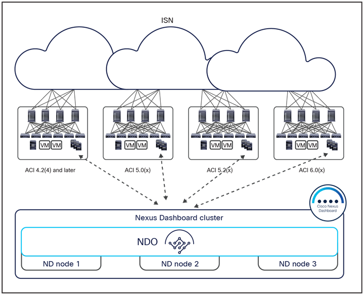
Inter-version support with Cisco Nexus Dashboard Orchestrator releases
It is worth noticing that Cisco ACI Release 4.2(4) represents the minimum APIC software version that can be part of a Multi-Site domain managed by NDO. This is dictated by the fact that the Nexus Dashboard compute platform does not allow the onboarding of fabrics running older versions.
In order to support the inter-version functionality, NDO must be aware of the ACI versions of the connected APIC domains. A WebSocket connection is therefore used between NDO and each APIC managed by NDO to retrieve this information. The purpose of this connection is to detect when an APIC goes down, so that NDO can query the APIC version when it comes back up; this is required, for example, during an APIC upgrade.
NDO can then check if specific functionalities configured on a template associated to a given site can effectively be supported on that fabric, based on its specific ACI release. Table 1, below, provides a non-exhaustive list of features and the corresponding minimum ACI release required for their support.
Table 1. ACI-specific functionalities and the required minimum APIC version for their support
| Feature |
Minimum APIC version |
| Cisco ACI Multi-Pod support |
Release 4.2(4) |
| Service graphs (L4-L7 services) |
Release 4.2(4) |
| External EPGs |
Release 4.2(4) |
| Cisco ACI Virtual Edge VMM support |
Release 4.2(4) |
| DHCP support |
Release 4.2(4) |
| Consistency checker |
Release 4.2(4) |
| Layer 3 multicast |
Release 4.2(4) |
| MD5 authentication for OSPF |
Release 4.2(4) |
| Host-based routing |
Release 4.2(4) |
| Intersite L3Out |
Release 4.2(4) |
| vzAny |
Release 4.2(4) |
| SR-MPLS handoff |
Release 5.0(1) |
An APIC version check can be performed by NDO in two ways:
● During the “Save” operation of a template: This is important to signal to the template designers early on that their configuration may be incompatible with their current APIC software release.
Version check during the “Save” operation of a template
● When trying to “Deploy” a template: This is required in case the user tries to deploy the template without saving it first. Also, it accounts for the case where the version checks all pass during the save operation, but an APIC is downgraded before the user actually tries to deploy the template.
APIC version check at deployment time for a template
Cisco ACI Multi-Site per bridge domain behavior
The Cisco ACI Multi-Site architecture can be positioned to fulfill different business requirements, including disaster avoidance and disaster recovery. Each specific use case essentially uses a different bridge-domain connectivity scenario, as discussed in the following sections.
Note: For more detailed configuration information on those use cases, please refer to the ACI Multi-Site deployment guide for ACI fabrics available at the link below: https://www.cisco.com/c/en/us/td/docs/dcn/whitepapers/cisco-multi-site-deployment-guide-for-aci-fabrics.html
Layer-3-only connectivity across sites
In many deployment scenarios, the fundamental requirement is to help ensure that only routed communication can be established across sites, as shown in Figure 40.
Layer-3-only connectivity across sites
No Layer 2 extension or flooding is allowed in this specific use case, and different bridge domains and IP subnets are defined in separate sites. As always in Cisco ACI, communication between EPGs can be established only after applying a proper security policy (that is, a contract between them), unless the policy component is removed to initially focus only on connectivity (leveraging, for example, the EPG preferred-group functionality available from Cisco ACI Release 4.0(2) or vzAny introduced in Cisco Multi-Site Orchestrator Release 2.2(4)). Different types of Layer 3 connectivity can be established across sites:
● Intra-VRF communication: In this case, typically the source EPG and destination EPG belong to different bridge domains mapped to the same VRF instance (the same tenant). The tenant and VRF instance are stretched across sites, and MP-BGP EVPN allows the exchange of host routing information, enabling intersite communication (Figure 41).
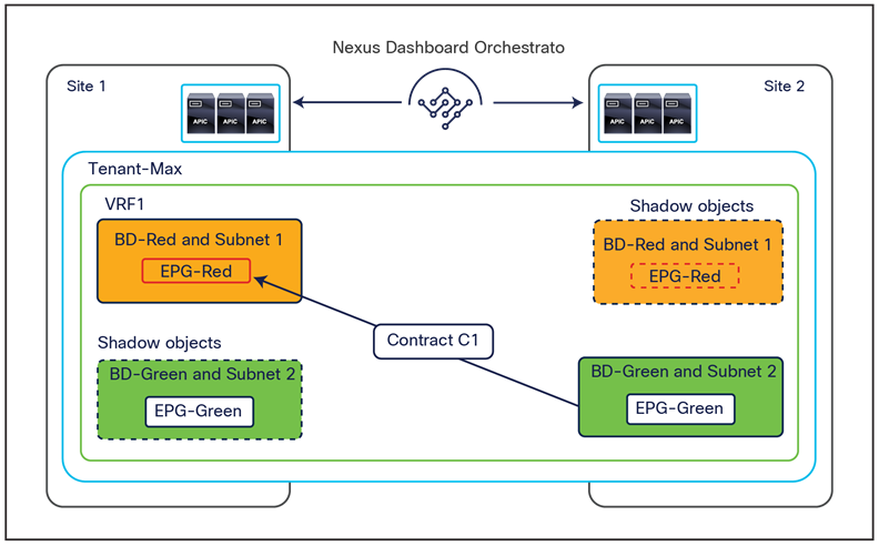
Layer 3 intra-VRF Layer 3 communication across sites
The establishment of the contract between EPG-Red and EPG-Green would cause the creation of the corresponding shadow objects in the remote sites, required to be able to properly program the translation entries in the spines.
One specific use case for intra-VRF Layer 3 communication across sites is shown in Figure 42, below.
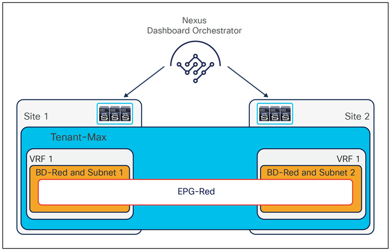
Intra-VRF Layer 3 communication across sites stretching an EPG
In this use case, an EPG is stretched across sites, but the BD associated to such EPG is not configured as a Layer 2 stretched object. This allows you to assign to the BD a different IP subnet in each site. Intersite communication between endpoints that are part of the EPG is therefore routed, but there is no requirement to create a contract since intra-EPG communication is allowed by default.
Note: In order to configure this use case on the Orchestrator, both the EPG and the BD must be defined in a template that is associated to both sites 1 and 2. The BD must then be configured with the “L2 Stretched” flag disabled. For more information on the definition of templates and their association to ACI sites, please refer to the “Deploying NDO schemas and templates” section.
● Inter-VRF communication: In this scenario, the source and destination bridge domains belong to different VRF instances (part of the same or different tenants), and the required route-leaking function to allow this communication is driven simply by the creation of a contract between the source and destination EPGs and by the configuration of the subnet under the provider EPG (as it is required on APIC for a single-site deployment). As shown in Figure 43, the establishment of a contract between the EPGs would result in the creation of the shadow objects in the remote sites.
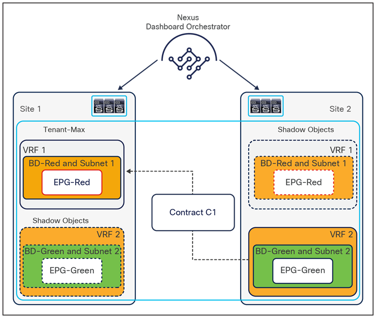
Layer 3 inter-VRF communication across sites
● Shared services: In one specific case of the inter-VRF communication scenario described earlier, multiple source IP subnets are placed in separate VRF instances or tenants that require access to a shared service offered in a separate VRF instance or tenant (Figure 44). This is a typical n:1 connectivity requirement, but again the required exchange of routing information is driven simply by the establishment of a proper security policy between the source and destination EPGs.
Note: In the figure below, we have not represented the shadow objects for simplicity of representation.
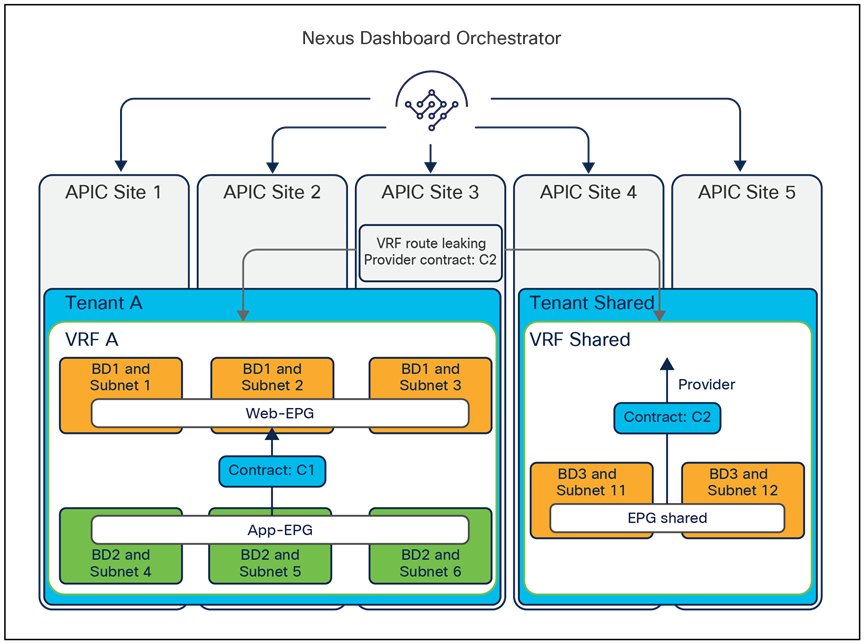
Inter-VRF communication across sites (shared services)
When discussing the deployment of Cisco ACI Multi-Site for Layer-3-only connectivity across sites, a typical question comes up: why using the VXLAN data path across the intersite network for this use case and not simply interconnect the separate Cisco ACI fabrics via L3Out logical connections established from the Border Leaf (BL) nodes?
Figure 45 shows this specific deployment model and the main deployment considerations associated to it.
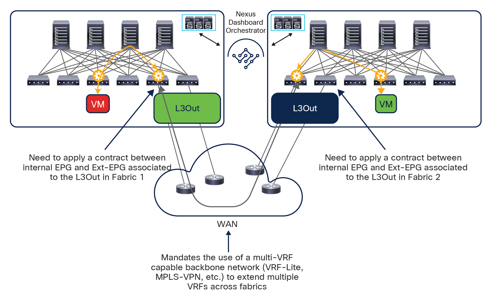
Interconnecting Cisco ACI fabrics for Layer 3 communication via L3Outs
● From a connectivity perspective, to support multi-VRF communication (multi-tenant deployment), the external network interconnecting the fabrics must provide the capability of supporting logically separated routed domains (VRFs or L3VPNs). This usually implies adopting options that are more costly (for example, purchasing multiple L3VPNs services from service providers) or more complex, such as VRF-Lite end-to-end or MPLSoGRE (to name just a few). On the other side, as it will be discussed in the “SR-MPLS/MPLS handoff on border leaf nodes” section, it may sometimes be desirable to provide full visibility to intersite flows across the WAN to be able to differentiate/prioritize them or to allow the transport team to monitor the DC-to-DC flows using existing monitoring tools. With a Multi-Site-native VXLAN data-path, as previously explained, the external network offers simply a routed infrastructure leveraged to establish site-to-site VXLAN tunnels that enable multitenant routing capabilities.
● From a policy perspective, the option depicted in Figure 45 represents the interconnection of disjoint policy domains, since the policy information is not carried with the data-plane traffic, given that the VXLAN encapsulation is terminated on the border-leaf nodes before sending the traffic to the external routers. This implies that traffic must be properly reclassified before entering the remote Cisco ACI fabric and that communication between EPGs in separate fabrics is only possible by creating two separate policies (one in each fabric), increasing the chances of dropping traffic because of operational errors. With the native Multi-Site functionalities, a single policy domain is extended across separate Cisco ACI fabrics and a single and simple policy definition is required on the Cisco Nexus Dashboard Orchestrator to ensure that endpoints that are part of different EPGs can securely communicate across sites.
● Finally, very often the initial requirements of providing Layer-3-only communication across sites evolves into the requirement to stretch IP subnets for various IP mobility use cases. Without Multi-Site, this requires the deployment of a separate Layer 2 Data-Center Interconnect (DCI) technology in the external network, which represents a deployment option not internally validated nor recommended anymore. As discussed in greater detail in the following two sections, a simple configuration on the Cisco Nexus Dashboard Orchestrator allows instead for bridge-domain extension across sites.
Important note: While the deployment model shown in Figure 45 has some drawbacks when compared to the use of a native VXLAN data path for intersite connectivity, it is still fully supported and a viable option when Layer-3-only communication is required between sites. The introduction of the Nexus Dashboard Orchestrator in such a design continues to offer the same advantage of representing a single pane of glass for the provisioning of the configuration in each fabric and for day-2 operations-related activities, and this specifically applies also to the use of NDO to manage “autonomous fabrics” previously discussed in this document. However, it is strongly recommended to choose one option or the other and not mix using a native VXLAN data-path with using an L3Out path for east-west connectivity between EPGs deployed in separate “Multi-Site” sites. In order to understand why, please refer to the example shown in Figure 46, below.
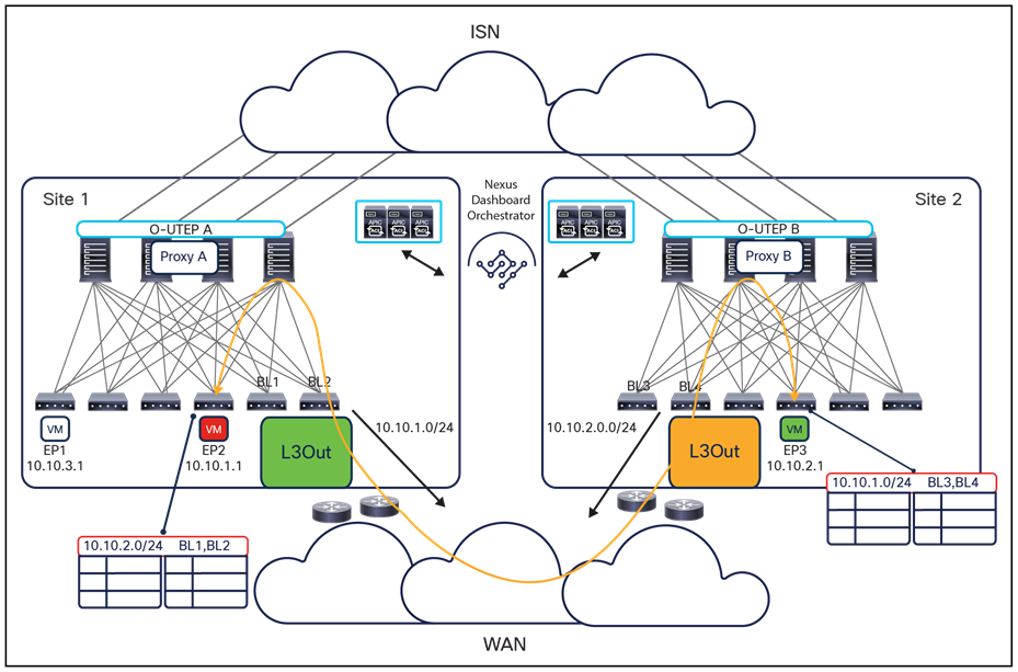
Initial state: Layer 3 intersite communication using the L3Out path
EP2 belonging to the Red EPG/BD locally defined in site 1 is communicating with EP3, part of the Green EPG/BD locally defined in site 2. This routing communication is established through the L3Out path, as the IP subnet of the Green BD (10.10.2.0/24) is received on the L3Out of the BL nodes in site 1, and vice versa for the IP subnet of the Red BD (10.10.1.0/24).
Now EP1 belonging to the Blue EPG/BD locally defined in site 1 is connected to the network, and a contract between the Blue EPG and the Green EPG is created in NDO to allow that communication to happen using VXLAN through the ISN (Figure 47).
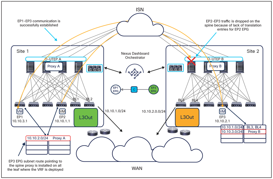
Issue when mixing VXLAN and L3Out traffic paths
The immediate consequence of the creation of the contract between the Blue and the Green EPG is the creation of shadow objects in both sites. Specifically, the creation of the Green BD shadow object in site 1 results also in the installation of a route for the Green BD subnet (10.10.2.0/24) in the routing table of all the leaf nodes where the corresponding VRF is installed. This route points to the proxy-spine VTEP address to enable communication via the ISN and replaces (since it is installed as a directly connected route) the information previously learned from the L3Out and used for establishing the communication between the Red EPG and the Green EPG shown in Figure 47.
As a result, also the traffic between the Red EPG and the Green EPG will start being sent through the VXLAN data path through the ISN. However, since a contract between Red and Green EPGs has not been configured in the NDO, there are no Red EPG/BD shadow objects created in site 2, and this implies that traffic will be dropped when received by the spines in site 2 because of the lack of corresponding translation entries.
The one shown in Figure 47 is just one specific example and not the only scenario that may lead to unexpected traffic drops. As a consequence, in order to avoid issues, it is critical to ensure that a clear decision is taken upfront whether to establish Layer 3 connectivity via the L3Out data path or via the VXLAN data path.
Layer 2 connectivity across sites without flooding
Cisco ACI Multi-Site architecture provides support for IP mobility across sites without requiring any Layer 2 flooding, which represents an important and quite unique functionality (Figure 48).
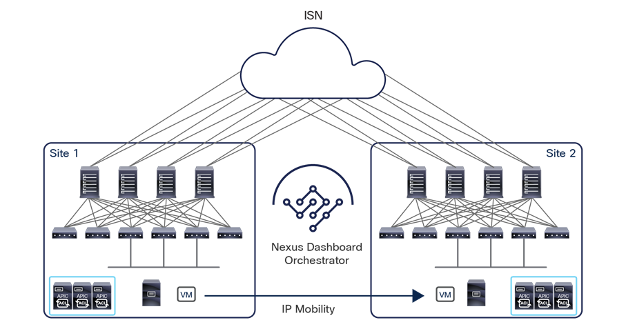
Layer 2 connectivity across sites without flooding
IP mobility support is needed in two main scenarios:
● For disaster-recovery scenarios (cold migrations) in which an application, initially running inside fabric 1, is moved to a different site. While this can be achieved by changing the IP address used to access the application and leveraging a DNS-based mechanism to point clients to the new IP address, in many cases the desire is to maintain the same IP address the application had while running in the original site.
● For business continuity scenarios (live migrations), it may be desirable to temporarily relocate workloads across sites without interruption to the access to the service that is being migrated. A typical example of functionality that can be used for this purpose is vSphere vMotion, as it will be discussed in more detail as part of the “Virtual machine manager integration models” section.
Note: Live migration across sites (with or without the enabling of broadcast, unknown-unicast, or multicast [BUM] flooding) is officially supported starting from Cisco ACI Release 3.2(1).
As shown in the logical view in Figure 48, this use case requires all the objects (tenants, VRF instances, bridge domains, and EPGs) to be stretched across the sites. However, in each specific bridge-domain configuration, you must specify that no Broadcast, Unknown-unicast, or Multicast (BUM) flooding be allowed across the sites.
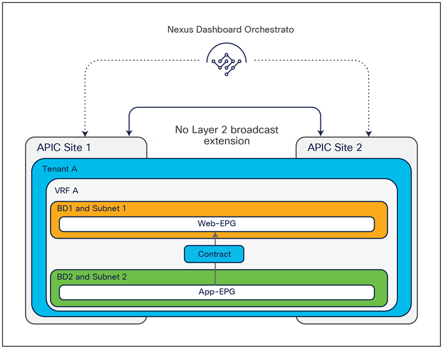
Layer 2 connectivity across sites without flooding (logical view)
The support of IP mobility without BUM flooding is a unique capability offered by the Cisco ACI Multi-Site architecture that is critical to allow flexible connectivity across sites without jeopardizing the overall resiliency of the architecture. An issue in a given bridge domain in a site (as, for example, a broadcast storm) can in fact be confined in that specific site without affecting other connected fabrics.
To support the IP mobility use case, the Cisco ACI Multi-Site solution provides several important functions:
● The relocated endpoint must be allowed to communicate with endpoints that are part of the same (or a different) IP subnet that may still be connected in the original site. To address this requirement, when an ARP request is sourced from the original site for the relocated endpoint, the Cisco ACI Multi-Site architecture must deliver that ARP request to the endpoint in the remote site. If the IP address of the migrated endpoint has been discovered by the fabric (which is normally the case for cold migration scenarios), the ARP request can be delivered across sites in unicast mode (by performing VXLAN encapsulation directly to the spines' anycast TEP address identifying the new site in which the destination endpoint is now connected).
If the IP address of the migrated endpoint is initially not discovered (which could be the case for hot migration if the migrated endpoint remains “silent” after the move), an “ARP Glean” functionality is performed by the spines in the original site to force the silent host to originate an ARP reply allowing its discovery. At that point, a newly originated ARP request would be delivered in unicast mode as described in the previous paragraph.
Note: ARP Glean is supported only for bridge domains that have one or more IP addresses defined, and not for Layer-2-only bridge domains.
● Traffic originating from the external Layer 3 domain must be delivered to the relocated endpoint. You need to consider several different scenarios, depending on the specific way that Layer-3-outside (L3Out) connectivity is established with the external network:
Traditional L3Out on Border Leaf (BL) nodes: Because the same IP subnet is deployed in both sites, usually the same IP prefix information is sent to the WAN from the two sites. This behavior implies that by default incoming traffic may be delivered indifferently to site 1 or site 2. However, commonly one of the two sites is nominated as the home site for that specific IP subnet (the site at which, at steady state, most of endpoints for that subnet are connected). In this case, routing updates sent to the WAN can be properly tuned to help ensure that all incoming traffic is steered toward the home site, as shown in Figure 50.
Note: For more information on this “home site” use case please refer to the “Cisco ACI Multi-Site and L3Out connections on border leaf nodes” section of this paper.
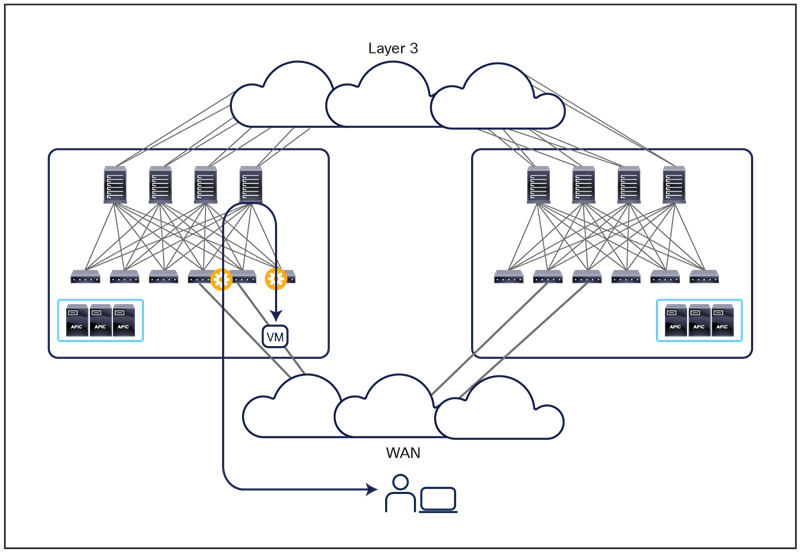
Ingress traffic steered toward the home site
The migration of a specific endpoint to site 2 most likely would not modify the behavior shown above, and ingress traffic would continue to be steered toward the IP subnet home site. Thus, the Cisco ACI Multi-Site architecture must be capable of directing the traffic flow across the intersite IP network to reach the destination endpoint, as shown in Figure 51.
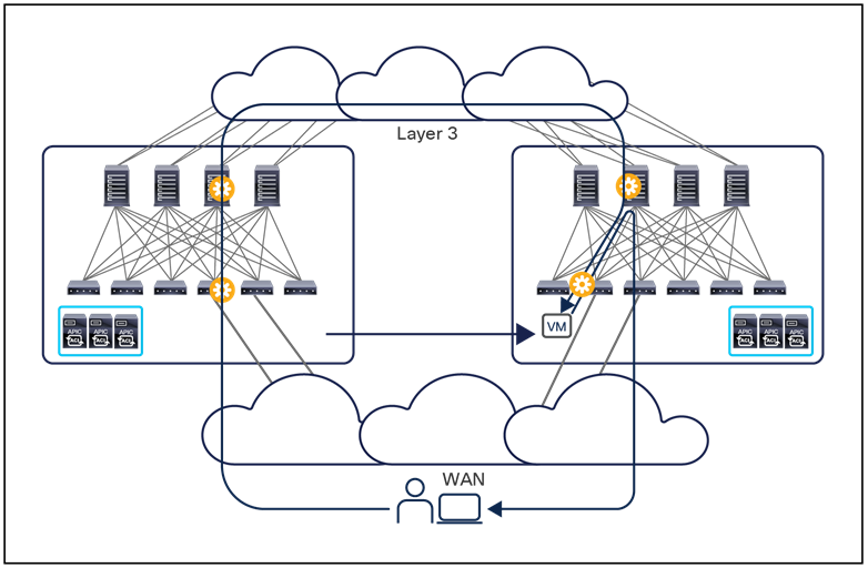
Bouncing traffic across sites toward the migrated endpoint
Again, this behavior is possible because of the dynamic discovery in site 2 of the migrated endpoint, which triggers an EVPN update from the spine nodes in site 2 to the spine nodes in site 1. This update essentially provides site 1 with the location information for the recovered endpoint required to redirect the traffic flows as shown in Figure 51.
Note that after the migration, the return traffic from the migrated endpoint toward the remote client starts using the local L3Out connection in Fabric 2, leading to the creation of an asymmetric traffic path. This behavior may lead to the drop of traffic in designs in which independent stateful firewalls are deployed between the fabrics and the WAN. This problem can be solved by leveraging a new functionality, supported on border leaf L3Outs from Cisco ACI Release 4.0(1), which allows advertising the most specific host-route information to the WAN.
Figure 52 shows how a host-route advertisement may be used only for the endpoints that are migrated away from the home site (in order to reduce the amount of host-route information injected into the WAN). For more considerations about Multi-Site and border leaf L3Out integration, refer to the section “Cisco ACI Multi-Site and L3Out connections on border leaf nodes.”
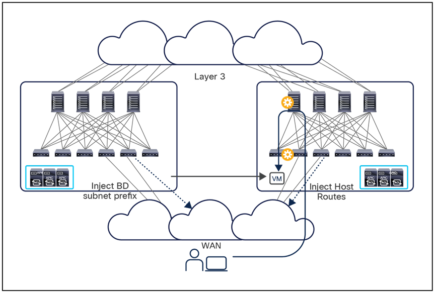
Host-route advertisement on border leaf L3Outs
b) GOLF L3Out: Deploying GOLF L3Out connections has allowed, since it was introduced (that is, from Cisco ACI Release 3.0(1)) to send to WAN edge devices, not only information about IP subnets, but also about specific host routes for endpoints connected to those subnets. As a consequence, in this case as well you can help ensure that ingress traffic is always steered to the site at which the endpoint is located, as shown in Figure 53.
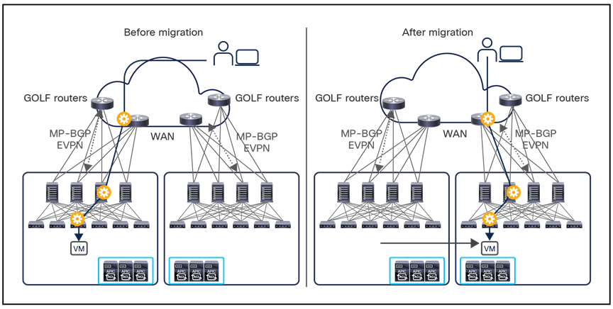
Ingress traffic optimization with GOLF L3Out
For more considerations about Multi-Site and GOLF integration, refer to the Appendix C.
Layer 2 connectivity across sites with flooding
In the next use case, the Cisco ACI Multi-Site design provides traditional Layer 2 stretching of bridge domains across sites, including the capability to flood Layer 2 BUM frames (Figure 54).
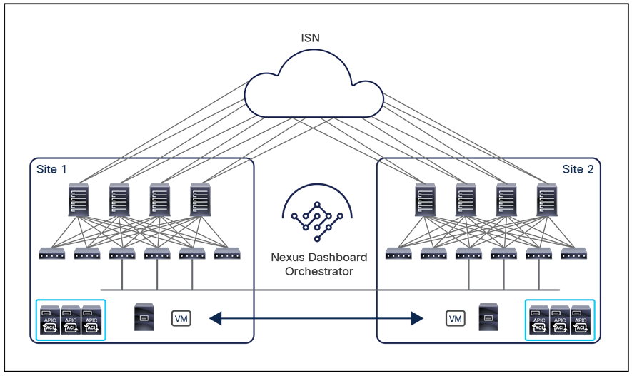
Layer 2 connectivity across sites with flooding
The need to flood BUM traffic is driven by specific requirements, such as application clustering (which traditionally calls for the use of Layer 2 multicast communication between different application cluster nodes).
Figure 55 shows the logical view for this use case, which is almost identical to the case shown earlier in Figure 49 except that now BUM flooding is enabled across sites.
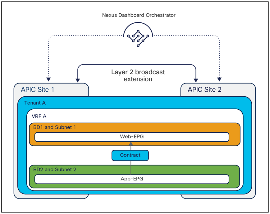
Layer 2 connectivity across sites with flooding (logical view)
Although Cisco ACI Multi-Pod usually would be positioned as the architectural choice for deployments requiring full Layer 2 flooding between Cisco ACI islands, one advantage offered by the Multi-Site design with this configuration is the capability to tightly control which bridge domains are extended (with or without enabling BUM forwarding) and which are kept local. Cisco Nexus Dashboard Orchestrator, in fact, allows you to differentiate the flooding behavior on a per–bridge-domain level, which is useful in a real-life scenario in which the flooding behavior must be supported only in a subset of the stretched bridge domains.
Intersite Network (ISN) deployment considerations
As previously mentioned, the different APIC domains are interconnected through a generic Layer 3 infrastructure, generically called the Intersite Network (ISN). Figure 56 shows a site-to-site VXLAN tunnel established across the ISN.
Note: In the rest of this document the terms “ISN,” “IP WAN,” and “IP network” can be used interchangeably (and shown in the figures) to refer to the routed network infrastructure providing network connectivity between the ACI fabrics that are part of the same Multi-Site domain.
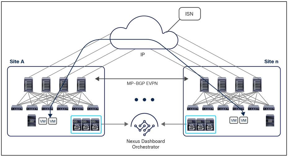
The ISN requires plain IP-routing support to allow the establishment of site-to-site VXLAN tunnels. This requirement means that the ISN can be built in an arbitrary way, ranging from a simple, single router device (two are always recommended, for redundancy) to a more complex network infrastructure spanning the world.
The spine interfaces are connected to the ISN devices through point-to-point routed interfaces. However, traffic originating from the spine interfaces is always tagged with an 802.1q VLAN 4 value, which implies the need to define and support Layer 3 subinterfaces on both the spines and the directly connected IPN devices. It is hence critical to select IPN routers that allow the defining of multiple subinterfaces on the same device using the same VLAN tag 4 and still functioning as separate point-to-point L3 links.
Note: The use of subinterfaces on the ISN devices is only mandatory for the connections toward the spines.
The ISN could be a network infrastructure dedicated to Multi-Site, but it is quite common in many real-life scenarios to use, for this purpose, a network that is also providing other connectivity services. In this latter case, it is strongly recommended to deploy a dedicated VRF routed domain to be used for the forwarding of Multi-Site control plane and data plane traffic. There are two reasons for this recommendation:
● The operational advantage of using a dedicated routing domain when there is the need to troubleshoot intersite connectivity issues (smaller routing tables, etc.)
● The requirement to prevent overloading the ACI “overlay-1” VRF with routing prefixes that are not needed. As previously mentioned, only a handful of prefixes must be exchanged across fabrics that are part of the same Multi-Site domain in order to establish intersite connectivity. There is actually a maximum number of routes allowed inside the ACI “overlay-1” routing space. Currently, this number is 1000 prefixes. Injecting more prefixes into this underlying routing domain may jeopardize the stability and functionality of the ACI spine nodes.
The ISN also requires MTU support above the default 1500-byte value. VXLAN data-plane traffic adds 50 bytes of overhead (54 bytes if the IEEE 802.1q header of the original frame is preserved), so you must be sure that all the Layer-3 interfaces in the ISN infrastructure can support the increase in MTU size (a generic recommendation is to support at least 100 bytes above the minimum MTU required end-to-end on all the interfaces of the ISN devices). This is because the ACI spine nodes are not capable of reassembling in hardware fragmented VXLAN frames. For example, if the spine of a source site 1 were to send out a large MTU packet toward the ISN and an ISN device was forced to fragment it before sending it out one of its interfaces (because of lower MTU support), the receiving spines in the destination site 2 would not be able to reassemble those fragments and would silently discard them, consequently breaking the intersite connectivity.
Note: If the frames get fragmented and reassembled inside the ISN infrastructure (for example, by source and destination ISN devices establishing IPsec connectivity with each other), the intersite connectivity could still be successfully established, since the destination spines would be handled a full-sized, non-fragmented frame. However, it is important to consider the performance implication in terms of throughput when adopting such a workaround; this mostly depends on the specific ISN platforms performing the fragmentation and reassembling duties.
The minimum MTU value to configure in the ISN depends on two factors:
● The maximum MTU of the frames generated by the endpoints connected to the fabric: If the endpoints are configured to support jumbo frames (9000 bytes), then the ISN should be configured with at least a 9050-byte MTU value. If the endpoints are instead configured with the default 1500-byte value, then the ISN MTU size can be reduced to 1550 bytes. This is the case except when the overhead of other encapsulations is also added to each frame, as it would be, for example, with IPsec encryption.
● The MTU of MP-BGP control-plane communication between spine nodes in different sites: By default, the spine nodes generate 9000-byte packets for exchanging endpoint routing information. If that default value is not modified, the ISN must support an MTU size of at least 9000 bytes; otherwise, the MP-BGP exchange of control-plane information across sites would not succeed (despite being able to establish MP-BGP adjacencies). The default value can be tuned by modifying the corresponding system settings in each APIC domain, as shown in Figure 57.
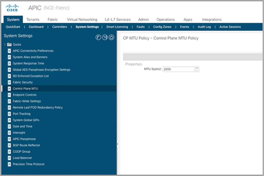
Control-plane MTU setting on Cisco APIC
Note: The global MTU setting shown in figure above applies also to the control plane protocols used inside the ACI fabric (IS-IS, COOP, MP-BGP VPNv4) and to the OSPF protocol used between the spines and the ISN devices. However, no significant performance impact has been noticed when reducing the maximum size for those control plane frames.
ISN and QoS deployment considerations
In specific deployment scenarios, it may be desirable to differentiate the QoS behavior for different intersite traffic flows. In order to understand what capabilities are offered from this point of view in a Multi-Site design, it is useful to quickly refresh how QoS works inside a specific ACI fabric.
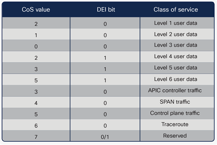
As shown in Figure 58, an ACI fabric supports multiple classes of services for handling traffic inside the fabric.
● Six user-configurable classes of services for user data (for example, tenant) traffic: Those classes are used for all user traffic received on leaf nodes from externally connected devices (endpoints, routers, service nodes, etc.). By default, all traffic received from those devices is assigned to the Level 3 class. This assignment can be modified based on the EPG (or Ext-EPG for L3Outs) that the external devices belong to, or based on the specific contract relationship established between EPGs.
The fabric administrator can tune (as part of the fabric-access policies configuration) specific properties associated to each of these user-level QoS classes, as minimum buffers, congestion algorithm, percentage of allocated bandwidth, etc.
Note: Only three user data classes are available up to Cisco ACI Release 4.0(1).
● Four reserved classes of services used for traffic between APIC controller nodes, control-plane traffic generated by the leaf and spine nodes, and SPAN and traceroute traffic.
The different traffic flows inside the ACI fabric are differentiated as belonging to those different QoS classes based on the specific value assigned to the CoS and DEI bits contained in the 802.1Q header of the VXLAN encapsulated packet.
This behavior represents an issue when VXLAN encapsulated traffic is sent toward the intersite network for communication between fabrics that are part of the same Multi-Site domain, since it is not possible to ensure that an 802.1Q header is present at all inside the ISN or that the value of those specific bits is preserved from end to end. A different mechanism is therefore required to be able to differentiate intersite traffic flows based on the specific QoS class they are supposed to belong to.
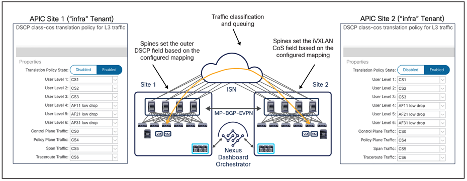
End-to-end consistent QoS behavior between ACI sites
Figure 59 shows how this goal can be achieved in a Multi-Site architecture: a specific mapping table is configured in each APIC domain to consistently map each QoS class to a specific Differentiated Services Code Point (DSCP) value set in the outer IP header of VXLAN encapsulated packets injected into the ISN. This functionality lets you achieve two goals:
● Allows you to properly associate traffic received on a remote ACI fabric to its proper QoS class based on the specific DSCP value carried in the packet: this ensures that you achieve consistent QoS treatment in the different ACI fabrics that are part of the same Multi-Site domain.
● Allows traffic classification and prioritization in the ISN infrastructure interconnecting the fabrics. For example, a basic and common recommendation is to always prioritize the MP-BGP control plane traffic between the spine nodes of different sites, to ensure that data traffic does not disrupt the overall stability of the Multi-Site deployment. Having six user-data classes allows you also to differentiate the services offered to traffic flows belonging to the same tenant or to different tenants.
Note: The configuration required on the ISN devices to classify and prioritize the different types of traffic depends on the specific hardware platforms deployed, and is out of the scope of this paper. Please refer to the specific product’s collateral material.
A basic assumption for achieving the two goals mentioned above is that the DSCP value not be modified by the devices in the ISN, because that would make it impossible to associate the traffic to the proper QoS class once the traffic is received in a remote site.
Also, the mapping between QoS groups and the correspondent DSCP values should be done directly on NDO, to ensure that a consistent mapping can be deployed to all the sites part of the Multi-Site domain. This configuration has been supported on all NDO releases and, starting from Cisco Nexus Dashboard Orchestrator Release 4.0(1), is part of the Fabric Policies template.
Cisco ACI Multi-Site underlay control plane
The ISN devices must use a routing protocol to establish adjacencies with the spine nodes deployed in each site and allow the intersite exchange of specific prefixes required for the establishment of intersite control and data planes, as shown in Figure 60.
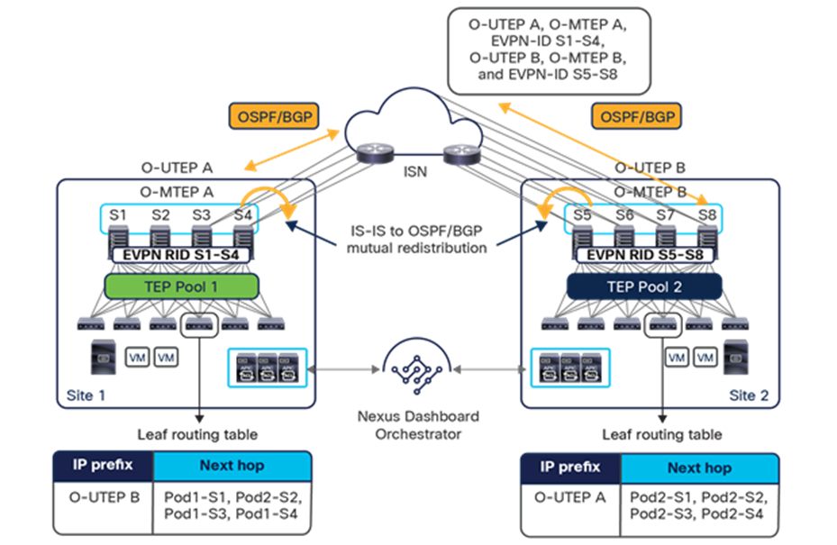
OSPF/BGP peering between the spine nodes in each site and the ISN
Initially, OSPF was the only supported control plane, but from NDO Release 3.5(1) BGP was also added as a viable option.
Note: The use of BGP also requires the deployment of Cisco ACI Release 5.2(1).
OSPF and BGP, which can be concurrently enabled when required, are used to exchange between sites routing information for specific IP addresses defined on the spine nodes:
● BGP-EVPN Router-ID (EVPN-RID): This unique IP address is defined on each spine node belonging to a fabric and is used to establish MP-BGP EVPN and VPNv4 adjacencies with the spine nodes in remote sites.
● Overlay Unicast TEP (O-UTEP): This common anycast address is shared by all the spine nodes in the same pod and is used to source and receive unicast VXLAN data-plane traffic. Each pod is characterized by an O-UTEP address that, essentially, uniquely identifies the site (for single pod fabric deployments).
Note: When deploying a Multi-Pod fabric, each pod gets assigned a unique O-UTEP address. For more information please refer to the “Integration of Cisco ACI Multi-Pod and Multi-Site” section.
● Overlay Multicast TEP (O-MTEP): This common anycast address is shared by all the spine nodes in the same site and is used to perform head-end replication for BUM traffic. BUM traffic is sourced from the O-UTEP address defined on the local spine nodes and destined for the O-MTEP of remote sites to which the given bridge domain is being stretched.
The definition of the O-UTEP and O-MTEP ensures that all the resources connected to a specific site are always seen as reachable from the remote sites through one of those two IP addresses (depending on if it is unicast traffic or BUM/multicast communication). This implies that when observing east-west VXLAN traffic exchanged between two sites in the ISN, all the packets will always be sourced from the O-UTEP address identifying the source site and destined to the O-UTEP (or O-MTEP) of the destination site. Notice that this does not prevent taking advantage of multiple ECMP links that may interconnect the two sites: when building the VXLAN encapsulated packet, a hashing of the L2/L3/L4 headers for the original frame generated by the endpoint is used as a UDP source port in the external header, and this allows you to build “entropy” in the packet. Different application flows between the same sites (and even between the same pair of endpoints) would cause the creation of different UDP source port values: as long as the network devices inside the ISN consider the L4 port information to choose the link to forward traffic, it will hence be possible to load-balance VXLAN packets across multiple paths.
As shown in Figure 60, the EVPN-RID, O-UTEP, and O-MTEP addresses are the only prefixes that must be exchanged across sites to enable the intersite EVPN control plane and the VXLAN data plane. Consequently, they are the only prefixes that should be learned in the ISN routing domain. This implies that those IP addresses must be globally routable across the ISN, which should normally not be a problem, because they are independent of the original TEP pools associated to each fabric and assigned separately on Cisco Nexus Dashboard Orchestrator at the time of Multi-Site deployment.
It is a best-practice recommendation to assign this handful of IP addresses from a dedicated IP range and to allow the advertisement of all those specific /32 prefixes across sites. If desired, it is also possible to summarize all the /32 prefixes used in a site and send only the summary route to the remote fabrics part of the Multi-Site domain. When doing that, an additional configuration step is required on all the remote APIC domains to ensure that the received summary routes can be redistributed to the IS-IS control plane internal to the fabric.
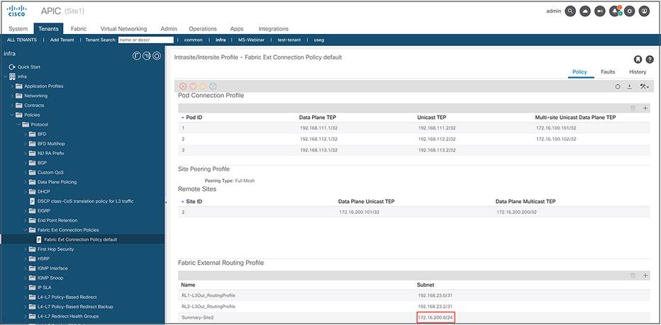
Defining a summary route for remote site 2 on the APIC of site 1
As shown in Figure 61, the summary prefix must be configured on APIC as part of the “Fabric External Routing Profile” policy defined for the “infra” tenant.
Note: The internal TEP pool prefixes used within each site, and assigned at the fabric bring-up time, do not need to be exchanged across sites to allow intersite communication. Therefore, there are no technical restrictions regarding how those pools should be assigned, and ACI fabrics using overlapping internal TEP pools could still be part of the same Multi-Site domain. However, the internal TEP pool summary prefix is always sent from the spines toward the ISN, because this is required for the integration of Cisco ACI Multi-Pod and Multi-Site architectures. It is therefore a best practice to ensure that those internal TEP pool prefixes are filtered on the first ISN device so that they are not injected into the ISN network (as they may overlap with the address space already deployed in the backbone of the network or in remote fabrics). For more information, please refer to the “Integration of Cisco ACI Multi-Pod and Multi-Site” section.
Note that multicast support is not required within the ISN routing domain to allow the exchange of Layer 2 multi-destination (BUM) traffic across pods in the specific use case in which a bridge domain is stretched with flooding enabled. This is because the Cisco ACI Multi-Site design uses the ingress replication function on the spine nodes of the source site to replicate BUM traffic to all the remote sites on which that bridge domain is stretched. For more information about this capability, refer to the section “Layer 2 BUM traffic handling across sites.”
Cisco ACI Multi-Site spines back-to-back connectivity
Starting from Cisco ACI Release 3.2(1), a back-to-back topology between the spines that are part of the separate fabrics is also supported, as shown in Figure 62.
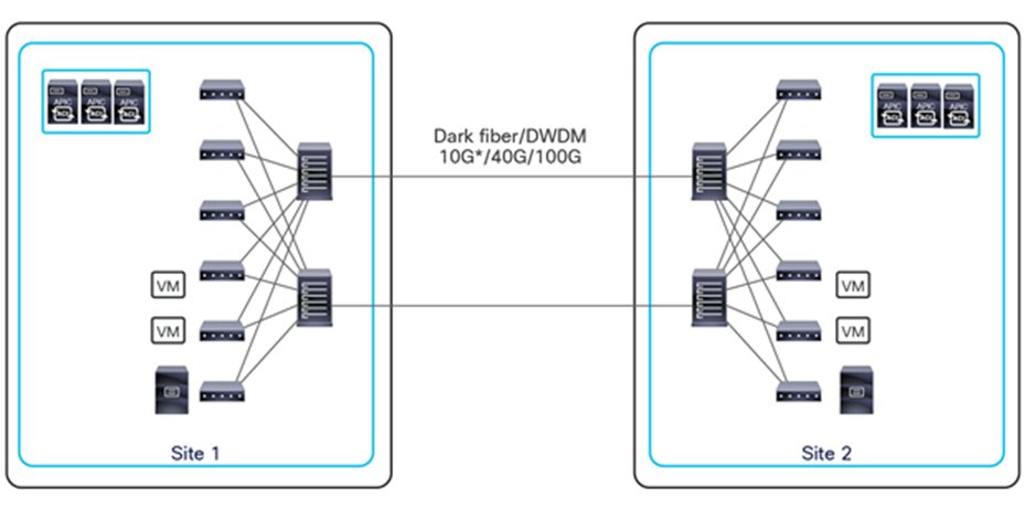
Cisco ACI Multi-Site spines back-to-back connectivity (from Cisco ACI Release 3.2)
Some important design considerations for this topology are the following:
● It is not mandatory to have all the deployed spines in a site connecting to the spines in the remote site; only a subset of the spines may be connected back to back across sites instead.
◦ The decision on how many spines/links to use is mainly a balance between cost to deploy those dedicated links and specific bandwidth/resiliency connectivity requirements
● MACsec encryption can be enabled when the requirement is to encrypt all communications between separate DC sites.
◦ Only two sites (fabrics) can currently be connected back to back. A topology with three or more sites connected with direct links is not supported, given the fact that the spines in a site are not capable of forwarding VXLAN-encapsulated communication between a different pair of sites. For the same reason, the deployment of a “hybrid” topology, where two sites are connected back to back and other remote sites are instead connected via a generic intersite network, is not supported (Figure 63).
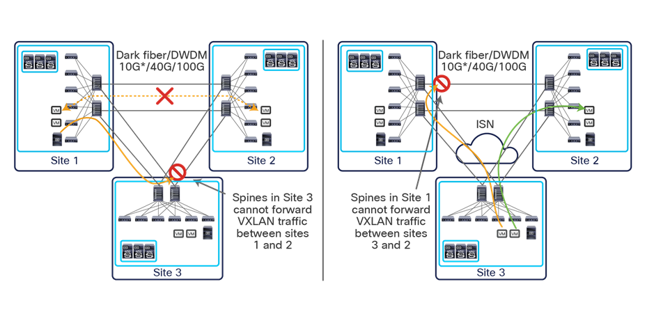
Back-to-back topologies that are not supported
The scenario to the left in the figure above shows how VXLAN traffic between sites 1 and 2 may be steered via the spine in site 3 because of the failure of the direct connections between them. The “hybrid” scenario on the right shows, instead, successful communication between Sites 3 and 2 when traffic is properly steered via the ISN directly to the spines in site 2. If, however, the same flows were steered via the spines in site 1 (for example, because of any rerouting in the ISN), communication between sites 3 and 2 would fail.
In a “hybrid” scenario where higher bandwidth connections are available between a pair of sites, the recommendation is to use those connections to establish direct connectivity between the first-hop intersite network devices (and not directly between the spine nodes), as shown in Figure 64.
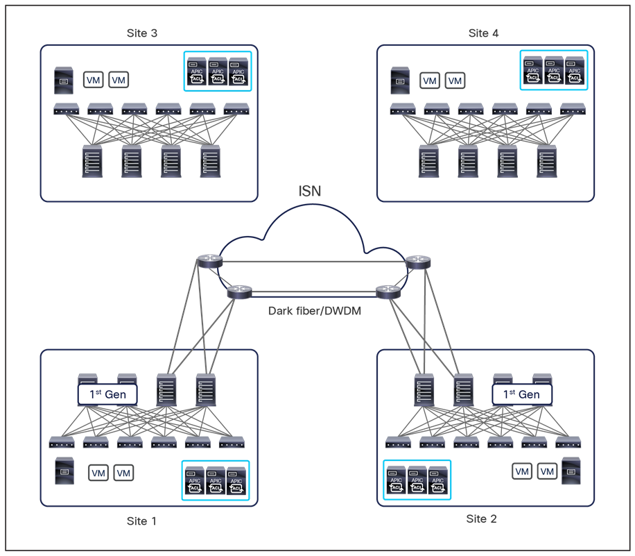
Connecting first-hop ISN routers back to back
● The spines may be connected with a square topology, as shown in Figure 62, above. Even in this topology, the spines would establish a full-mesh BGP peering with the spines in the remote site (assuming that the route-reflector configuration is not in place), but the outbound data-plane traffic on each spine would obviously flow on the single link connecting them to the remote spines. All the BUM traffic across sites is always originated by the specific spine that has been elected as Designated Forwarder for that bridge domain, and it is destined to the O-MTEP address. The receiving spine will then forward the BUM traffic inside the local site (there is no need to elect a designated forwarder role for this function on the receiving site).
◦ Despite what is mentioned above, the best-practice topology consists in creating full-mesh connections between the spines in separate sites. Doing that brings two immediate advantages in failure scenarios such as the one of the remote spine shown in Figure 65: for Layer-2/Layer-3 unicast communication across sites, traffic recovery simply requires a local reshuffling of the VXLAN traffic on the remaining connections available on each local spine. The same consideration applies to Layer 2 BUM traffic across sites, where no re-election of the local designated forwarder is necessary (because it still remains connected to at least a different remote spine).
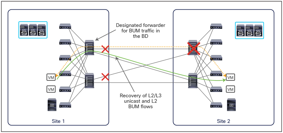
Traffic recovery in remote spine’s failure scenario with full-mesh connections
Note: The traffic recovery, shown above, happens under the assumption that all L2/L3 unicast traffic and BUM traffic were flowing along the dotted line before the remote spine failure event.
● The spines deployed in separate sites must be directly connected (logically or physically). This means that the deployment of a Layer 2 infrastructure between them is not supported and the use of dark fibers or DWDM circuits is required.
◦ Use of EoMPLS pseudowires is also possible, as those can be used to logically extend the point-to-point connection between spines in separate sites across an MPLS core network.
Cisco ACI Multi-Site and site-to-site traffic encryption (CloudSec)
The use of CloudSec in conjunction with ACI Multi-Site is not recommended anymore because of a discovered vulnerability in the Cisco ACI Multi-Site CloudSec encryption feature of Cisco Nexus 9000 Series Fabric Switches in ACI mode. For more information please refer to the security advisory notice below: https://sec.cloudapps.cisco.com/security/center/content/CiscoSecurityAdvisory/cisco-sa-aci-cloudsec-enc-Vs5Wn2sX
Cisco ACI Multi-Site overlay control plane
In a Cisco ACI fabric, information about all the endpoints connected to the leaf nodes is stored in the COOP database available in the spine nodes. Every time an endpoint is discovered as locally connected to a given leaf node, the leaf node originates a COOP control-plane message to communicate the endpoint information (IPv4/IPv6 and MAC addresses) to the spine nodes. COOP is also used by the spines to synchronize this information between them.
In a Cisco ACI Multi-Site deployment, host information for discovered endpoints must be exchanged between spine nodes that are part of separate fabrics to allow east-west communication between endpoints. This intersite exchange of host information is required only for the endpoints that really need to communicate: this include endpoints part of EPGs stretched across sites (since intra-EPG communication is allowed by default without requiring any contract definition), and endpoints connected to non-stretched EPGs with a defined contract to allow communication between them. This controlled behavior is important because it allows you to increase the overall number of endpoints that can be supported across sites, because only information for a subset of those endpoints is synchronized across sites.
Note: You can control the exchange of endpoint information at the bridge domain level. Therefore, if multiple EPGs are part of the same bridge domain and a specific policy dictates the exchange of routes for one of those EPGs, endpoint information also will be sent for all the other EPGs. Also, as previously discussed, the deployment of EPGs as part of preferred groups or the use of vzAny to provide/consume a “permit-all” contract would enable the exchange of host routing information for all the endpoints discovered as part of those EPGs.
Figure 66 shows in detail the sequence of overlay control-plane events.
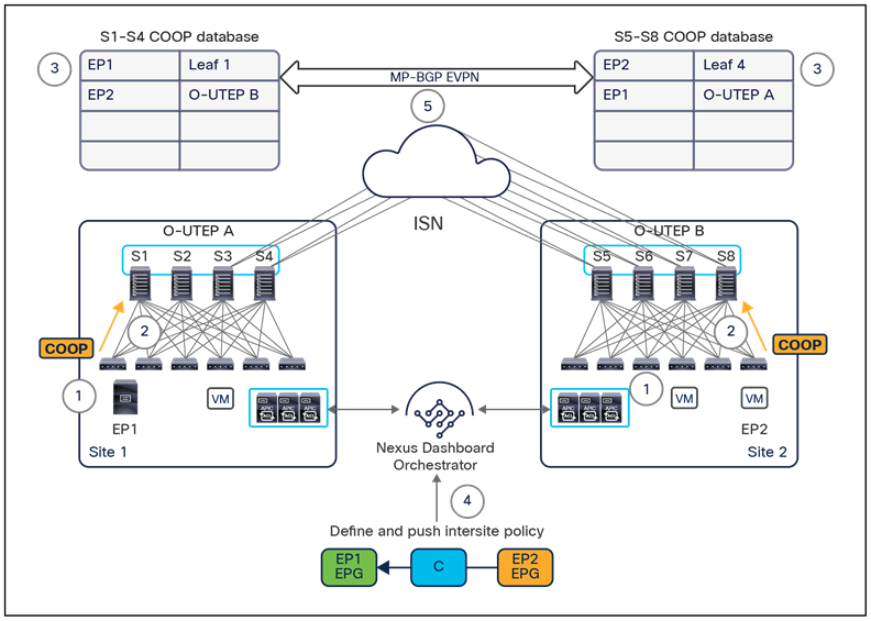
Cisco ACI Multi-Site overlay control plane
1. Endpoints EP1 and EP2 connect to separate Sites 1 and 2.
2. A COOP notification is generated inside each fabric from the leaf nodes on which EP1 and EP2 are discovered and sent to the local spine nodes.
3. The endpoint information is stored in the local COOP database. Spine nodes in site 1 know about locally connected endpoints, and the same is true for spine nodes in site 2. Note that at this point no information is exchanged across sites for EP1 and EP2 EPGs, because there is no policy in place yet indicating a need for those endpoints to communicate.
4. An intersite policy is defined in Cisco Nexus Dashboard Orchestrator and is then pushed and rendered in the two sites.
5. The creation of the intersite policy triggers Type-2 EVPN updates across sites to exchange EP1 and EP2 host route information. Note that the endpoint information always is associated with the O-UTEP address, univocally identifying the site at which each specific endpoint was discovered. Therefore, no additional EVPN updates are required when an endpoint moves around different leaf nodes that are part of the same fabric, until an endpoint is migrated to a different site.
Note: It is worth remarking how only EVPN Type-2 updates are always sent across sites for communicating specific endpoint host route information. EVPN Type-5 routing updates are not used in the current implementation of Cisco ACI Multi-Site for intersite advertisement of IP subnet prefixes associated to bridge domains. EVPN Type-2 updates are always used independently from the fact that the BDs with connected endpoints are L2-stretched or locally defined in each site.
As previously mentioned, MP-BGP EVPN adjacencies are established between spine nodes belonging to different fabrics by using the EVPN-RID addresses. Both MP Interior BGP (MP-iBGP) and MP External BGP (MP-eBGP) sessions are supported, depending on the specific BGP autonomous system to which each site belongs. When deploying eBGP sessions across sites, a full mesh of adjacencies are automatically created by NDO, where each site’s spine connected to the external IP network establishes EVPN peerings with all the remote spine switches, as shown in Figure 67.
Full mesh of EVPN sessions across sites
When iBGP is used across sites, you can instead decide whether to use a full mesh or to introduce route-reflector nodes, usually referred to as External-RRs (Ext-RRs). The recommendation is to keep the default behavior of using full-mesh peering also for iBGP deployments, given the fact that the expectation is that a limited number of sites (that is, fewer than 20) will likely always be interconnected and this does not pose any scalability concern.
If, however, the desire is to introduce the route-reflectors, you should deploy a few Ext-RR nodes and place each node in a separate site to help ensure resiliency. The external route-reflector nodes peer with each other and with all the remote spine nodes, as shown in Figure 68.
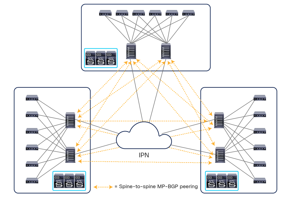
Use of external route reflectors for MP-iBGP EVPN deployments across sites
The best-practice recommendations for the deployment of Ext-RR nodes, due to specific internal implementation, are the followings:
● Ensure that any spine node that is not configured as Ext-RR is always peering with at least one remote Ext-RR node. Since spines do not establish intra-site EVPN adjacencies, this implies that a spine that is not configured as an Ext-RR node should always peer with two remote Ext-RRs (in order to continue to function if a remote Ext-RR node should fail). This means it makes little sense to configure Ext-RRs for a two-site deployment, since it does not provide any meaningful savings in terms of overall EVPN adjacencies that need to be established across the sites.
◦ For a three (or more) site deployment, define one Ext-RR node in the first three sites only (three Ext-RR nodes in total), as shown in Figure 68, above.
Note: The Ext-RR nodes discussed above are used for the MP-BGP EVPN peerings established between spine nodes deployed in separate sites. They serve a different function from that of the internal RR nodes, which are always deployed for distributing to all of the leaf nodes that are part of the same fabric external IPv4/IPv6 prefixes learned on the L3Out logical connections.
Cisco ACI Multi-Site overlay data plane
After endpoint information is exchanged across sites, the VXLAN data plane is used to allow intersite Layer 2 and Layer 3 communication. Before exploring in detail how this communication can be established, you should understand how Layer 2 multi-destination traffic (usually referred to as BUM) is handled across sites.
Layer 2 BUM traffic handling across sites
The deployment of VXLAN allows the use of a logical abstraction so that endpoints separated by multiple Layer 3 hops can communicate as if they were part of the same logical Layer 2 domain. Thus, those endpoints must be capable of sourcing Layer 2 multi-destination frames so that they can be received by all the other endpoints connected to the same Layer 2 segment, regardless of their actual physical location.
This capability can be achieved in one of two ways: by using the native multicast replication functions offered by the Layer 3 infrastructure interconnecting the endpoints or by enabling ingress replication functions on the source VXLAN TEP (VTEP) devices, which create multiple unicast copies of each BUM frame to be sent to all the remote VTEPs on which those endpoints part of the same Layer 2 domain are connected.
The Cisco ACI Multi-Site design adopts this second approach for intersite BUM forwarding, with the Multi-Site-capable spine switches performing the ingress replication function, because the interconnected fabrics may be deployed around the world, and it would be difficult to ensure proper multicast support across the entire interconnecting network infrastructure (the approach adopted instead in the Cisco ACI Multi-Pod architecture).
The transmission of Layer 2 BUM frames across sites is required only for the specific bridge domains that are stretched with flooding enabled (that is, the “Intersite BUM Traffic Allow” flag is configured for the bridge domains). There are three different types of Layer 2 BUM traffic, and below is described the intersite forwarding behavior for each of them when BUM is allowed across sites for a given bridge domain. The assumption here is that specific bridge domain configuration knobs are not modified at the APIC level, but the configuration for the bridge domain is only controlled at the Cisco Nexus Dashboard Orchestrator level.
● Layer 2 Broadcast frames (B): Those are always forwarded across sites. A special type of Layer 2 broadcast traffic is ARP; specific considerations can be found as part of the “Intra-subnet unicast communication across sites” section.
● Layer 2 Unknown Unicast frames (U): Those frames, by default, are not flooded across sites but are instead forwarded in unicast mode, assuming that the destination MAC is known in the COOP database of the local spines (else the traffic will be dropped by the receiving spine). However, there is the possibility of changing this behavior on the bridge-domain-specific configuration of Cisco Nexus Dashboard Orchestrator by selecting the “flood” option associated to the “L2 UNKNOWN UNICAST” traffic.
● Layer 2 Multicast frames (M): The same forwarding behavior applies to intra-bridge-domain Layer 3 multicast frames (that is, the source and receivers are in the same or different IP subnets but part of the same bridge domain) or to “true” Layer 2 multicast frames (that is, the destination MAC address is multicast and there is no IP header in the packet). In both cases, the traffic is forwarded across the sites where the bridge domain is stretched once BUM forwarding is enabled for that bridge domain.
Note: What is mentioned above applies assuming that multicast routing is not enabled. For more considerations about support of multicast routing with Cisco ACI Multi-Site, please refer to the “Multi-Site Layer 3 multicast” section.
Figure 69 shows the sequence of events required to send a Layer 2 BUM frame across sites.
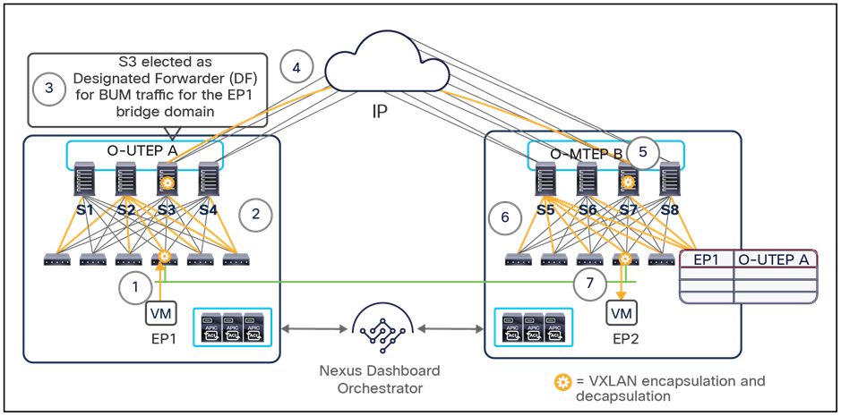
Layer 2 BUM traffic across sites
1. EP1, belonging to a specific bridge domain, generates a Layer 2 BUM frame.
2. Depending on the type of frame and the corresponding bridge domain settings (as previously clarified above), the leaf may need to flood the traffic in that specific Layer 2 domain. As a consequence, the frame is VXLAN-encapsulated and sent to the specific multicast group (called GIPo) associated with the bridge domain within the fabric along one of the specific multi-destination trees associated to that GIPo, so it can reach all the other leaf and spine nodes.
3. One of the spine nodes connected to the external intersite network is elected as the designated forwarder for that specific bridge domain (this election is held between the spine nodes using IS-IS protocol exchanges). The designated forwarder is responsible for replicating each BUM frame for that bridge domain to all the remote sites with the same stretched bridge domain.
4. The designated forwarder makes copies of the BUM frame and sends it to the remote sites. The destination IP address used when VXLAN encapsulating the packet is the special IP address (O-MTEP) identifying each remote site and is used specifically for the transmission of BUM traffic across sites. The O-MTEP is another anycast IP address defined on all the remote spine nodes that are connected to the intersite network (each site uses a unique O-MTEP address). The source IP address for the VXLAN-encapsulated packet is instead the anycast O-UTEP address deployed on all the local spine nodes connected to the intersite network.
Note: The O-MTEP (referred to as “Overlay Multicast TEP” in the Cisco Nexus Dashboard Orchestrator GUI) is yet another IP address that must be sent to the Layer 3 network connecting the fabrics.
5. One of the remote spine nodes receives the packet, translates the VNID value contained in the header to the locally significant VNID value associated with the same bridge domain, and sends the traffic to the site along one of the local multi-destination trees defined for the bridge domain (using the multicast group locally assigned to the BD as destination in the VXLAN header).
6. The traffic is forwarded within the site and reaches all the spine and leaf nodes with endpoints actively connected to the specific bridge domain.
7. The receiving leaf nodes use the information contained in the VXLAN header to learn the site location for endpoint EP1 that sourced the BUM frame. They also send the BUM frame to all (or some of) the local interfaces associated with the bridge domain, so that endpoint EP2 (in this example) can receive it.
As previously mentioned, any defined bridge domain is associated with a multicast group address (or a set of multicast addresses), usually referred to as the GIPo address. Depending on the number of configured bridge domains, the same GIPo address may be associated with different bridge domains. Thus, when flooding for one of those bridge domains is enabled across sites, BUM traffic for the other bridge domains using the same GIPo address is also sent across the sites and will then be dropped on the received spine nodes. This behavior can increase the bandwidth utilization in the intersite network.
Because of this behavior, when a bridge domain is configured as stretched with BUM flooding enabled from the Cisco Nexus Dashboard Orchestrator GUI, by default a GIPo address is assigned from a separate range of multicast addresses. This is reflected in the GUI by the “OPTIMIZE WAN BANDWIDTH” flag, which is enabled by default for BDs that are created directly on NDO, as shown in Figure 70.
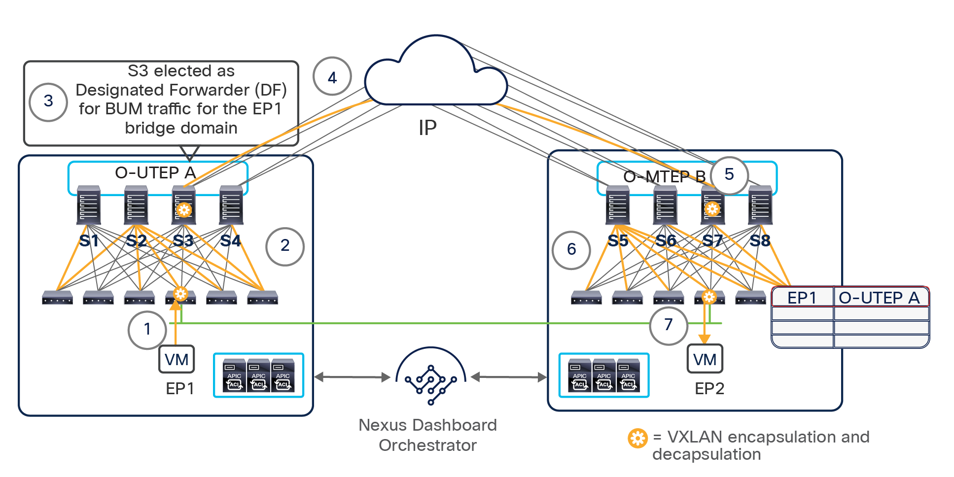
Optimizing BUM flooding across sites
If, however, a bridge domain configuration is imported from an APIC domain, by default the flag is disabled, so you will need to manually configure it to change the GIPo address already associated with the bridge domain. Note that doing so will cause a few seconds of outage for the intra-fabric BUM traffic for the bridge domain while the GIPo address is updated on all the leaf nodes on which that specific bridge domain is deployed.
Intra-subnet unicast communication across sites
The first requirement before intra-subnet IP communication across sites can be achieved is to complete the ARP exchange between source and destination endpoints. As previously mentioned, ARP represents a special type of Layer 2 broadcast traffic, and its forwarding across sites can be controlled at the bridge domain level.
Note: The assumption for the discussion below is that the bridge domain has associated a single IP subnet, even if there may be scenarios where that is not the case and multiple subnets are defined for the same bridge domain.
There are two different scenarios to consider:
● ARP flooding is enabled in the bridge domain: This is the default configuration for stretched bridge domains created on Cisco Nexus Dashboard Orchestrator with BUM forwarding enabled. In this case, the behavior is identical to that discussed in the previous section and shown in Figure 70. The ARP request will reach the destination endpoints in remote sites, which will allow the remote leaf nodes to learn the site location of the source endpoint. As a consequence, the ARP unicast reply will be directly VXLAN-encapsulated to the O-UTEP address identifying the EP1 site, and one of the receiving spine nodes will perform the VNID and class-ID translation and send the frame toward the local leaf node to which EP1 is connected, as shown in Figure 71.
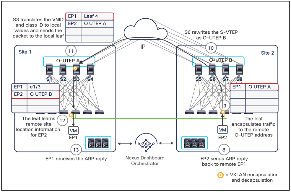
ARP reply delivered to EP1 in site 1
Notice that the reception of the ARP reply allows the leaf node in site 1 to learn the site’s information for EP2 (EP2 is associated with the O-UTEP B address identifying the spine nodes at the EP2 site).
Note: Enabling ARP flooding for the bridge domain (at the APIC level) without the corresponding enablement of BUM forwarding represents a misconfiguration that would prevent the completion of the ARP exchange across sites, consequently breaking intra-bridge-domain connectivity across sites. It is strongly recommended to configure the BD forwarding characteristics only on the Nexus Dashboard Orchestrator to prevent this type of issue.
● ARP flooding is disabled in the bridge domain: This is the default configuration for stretched bridge domains created on Cisco Nexus Dashboard Orchestrator with BUM forwarding disabled. In this case, the ARP request received by the local spines cannot be flooded across sites, so you must be sure that they are encapsulated in the VXLAN unicast packet, as shown in Figure 72.
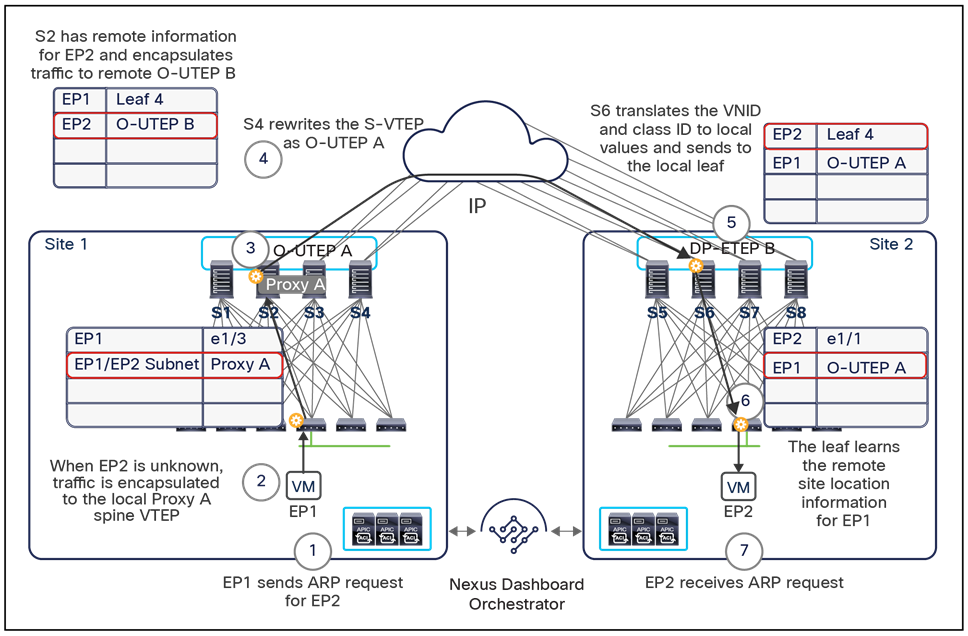
ARP request across sites without flooding
The following is the sequence of steps required in this specific use case to send the ARP request to site 2:
1. EP1 generates an ARP request for the EP2 IP address.
2. The local leaf node inspects the ARP payload and determines the IP address of the target EP2. Assuming that EP2’s IP information is initially unknown on the local leaf, the ARP request is encapsulated and sent toward the Proxy A anycast VTEP address defined on all the local spines (based on the pervasive EP1/EP2 IP subnet information installed in the local routing table) to perform a lookup in the COOP database.
3. One of the local spine nodes receives the ARP request from the local leaf node.
4. The capability of forwarding ARP requests across sites in “unicast mode” is mainly dependent on the knowledge in the COOP database of the IP address of the remote endpoint (information received via the MP-BGP EVPN control plane with the remote spines). Considering initially the case where the IP address of the remote endpoint is known (that is, EP2 is not a “silent host”), the local spine nodes know the remote O-UTEP address identifying the site to which EP2 is connected and can encapsulate the packet and send it across the ISN toward the remote site. It is worth noticing that the spines also rewrite the source IP address of the VXLAN-encapsulated packet, replacing the VTEP address of the leaf node with the local O-UTEP A address identifying the local site. This operation is very important, because, as previously mentioned, when describing the EVPN control-plane exchange across sites, only the EVPN-RID and O-UTEP/O-MTEP addresses of the spine nodes should be visible in the external IP network.
5. The VXLAN frame is received by one of the remote spine nodes, which translates the original VNID and class-ID values to locally significant ones and encapsulates the ARP request and sends it toward the local leaf nodes to which EP2 is connected.
6. The leaf node receives the frame, decapsulates it, and learns the class-ID and site location information for remote endpoint EP1.
7. The frame is then sent out the interface on which the EP2 is learned and reaches the endpoint.
At this point, EP2 can reply with a unicast ARP response that is delivered to EP1 with the same sequence of steps described previously in Figure 71 (the only difference is that flooding is not enabled across sites).
If, instead, at previous step 4 the IP address of the remote endpoint was not known in the COOP database in site 1, from Cisco ACI Release 3.2(1) a new “ARP Glean” function has been introduced to ensure that the remote “silent host” can receive the ARP request, then reply and be discovered in the remote site, as shown in Figure 73, below.
Note: The “ARP Glean” message is sourced from the anycast gateway IP address associated to the bridge domain. This implies that the ARP reply is always locally consumed by the leaf node where EP2 is connected, but this process allows discovery of EP2 (which at that point is no longer “silent”).
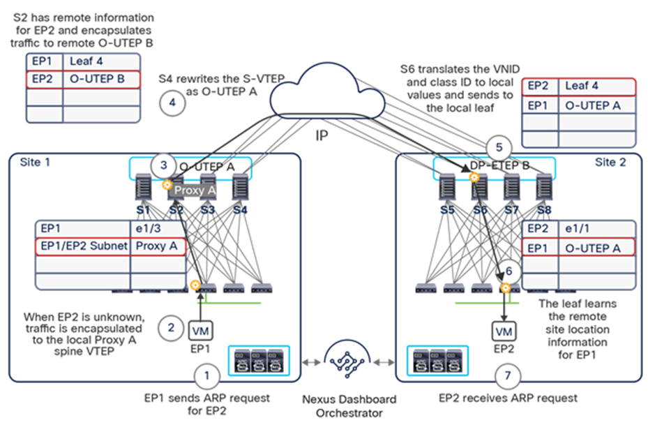
ARP Glean functionality for intra-subnet communication use case
Once the IP address of the remote endpoint is discovered and communicated across sites through the EVPN control plane, the ARP request originated by EP1 can then be sent in unicast mode across toward EP2 as previously described in Figure 72.
At the completion of the ARP exchange process described above, each leaf node has full knowledge of the class ID and location of the remote endpoints that are trying to communicate. Thus, from this point on the traffic will always flow in the two directions, as shown in Figure 74, in which a leaf node at a given site always encapsulates traffic and sends it toward the O-UTEP address that identifies the site to which the destination endpoint is connected.
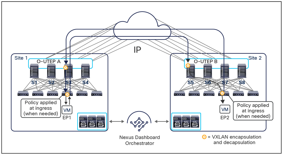
Intra-subnet communication across sites
From a security policy enforcement perspective, there are three main scenarios to consider for the intra-subnet communication use case:
● EP1 and EP2 are in the same EPG and bridge domain, and no microsegmentation is configured (and the EPG is not configured as isolated): In this case, no policy is applied, and EP1 can freely communicate with EP2.
● EP1 and EP2 are in the same base EPG and bridge domain but associated with two micro-EPGs with a specific contract between them: In this case, at steady state the policy is always applied at ingress on the source leaf node.
● Note: Disabling data-plane learning would modify this behavior and cause the enforcement of policy to always happen on the egress leaf nodes.
● EP1 and EP2 are in two different EPGs that are part of the same bridge domain and IP subnet: In this case, communication is dictated by the contract defined between them, and as in the previous case, at steady state the policy is usually applied at ingress on the source leaf node. The exception to this is if the contract has associated a service graph with Policy-Based Redirect (PBR). In that case, as discussed in more detail in the “Network services integration” section, the policy enforcement depends on where the consumer and provider endpoints are connected.
Inter-subnet unicast communication across sites
The considerations and functions for enabling inter-subnet communication across sites are similar to those discussed in the previous section for intra-subnet communication. If the source and the destination endpoints are part of different EPGs (belonging to different bridge domains or to the same bridge domain that has multiple IP subnets configured), a contract must be created between the EPGs on Cisco Nexus Dashboard Orchestrator to enable east-west communication between them. If, instead, the source and destination endpoints are part of the same EPG, even if in different IP subnets, the routing will happen as discussed below without the need to configure a contract. Also, the source endpoint will always resolve the ARP information for its default gateway with the local leaf node to which it connects and then send the data packet destined for the remote endpoint to it. The leaf node will then need to deliver the traffic to the destination endpoint, and, assuming that the destination bridge domain is not stretched across sites, two possible scenarios are possible:
● EP2’s IP address has not been discovered yet in site 2, and as a consequence, it is not known in the source site 1: before Cisco ACI Release 3.2(1), the local spine receiving the traffic from the leaf would perform a lookup, and because EP2 is unknown, traffic will be dropped. The “ARP Glean” functionality introduced in Cisco ACI Release 3.2(1) can be invoked also in this case to allow for the discovery of EP2’s IP address, as shown in Figure 75.
● Once EP2 is discovered, data-plane communication can be established to it as discussed in the following bullet point.
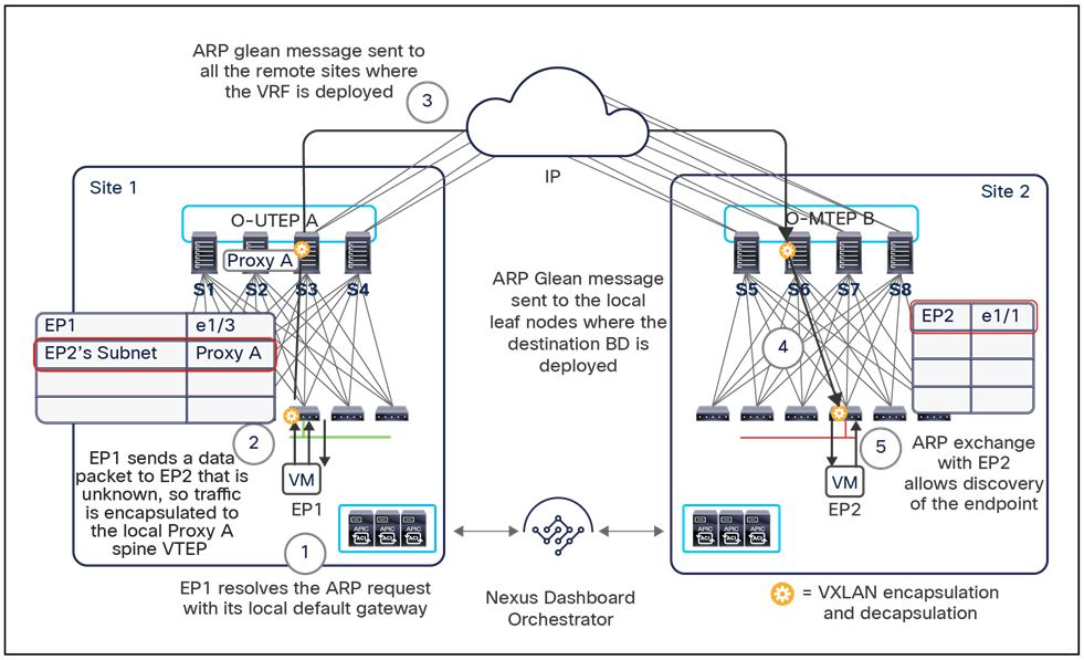
ARP Glean functionality for an inter-subnet communication use case
● EP2’s IP address is known in the COOP database of the spines belonging to source site 1: In this case, the local spine node will encapsulate traffic to the O-UTEP address that identifies the remote site to which EP2 belongs, and the packet will eventually be received by the destination endpoint, as shown in Figure 76.
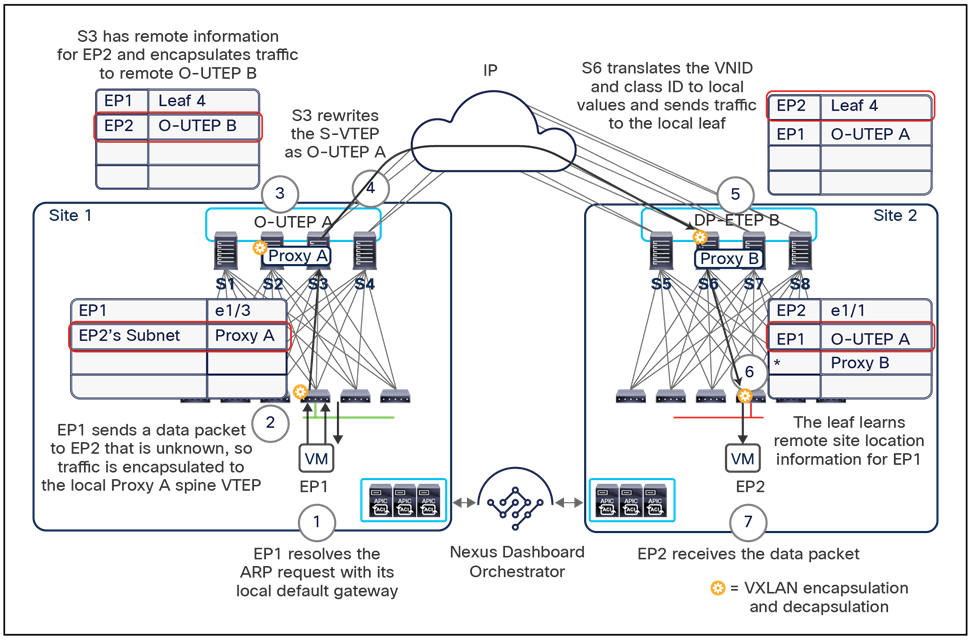
Delivering inter-subnet traffic across sites
Multi-Site Layer 3 multicast (Tenant Routed Multicast – TRM)
Support for Layer 3 multicast communication with Cisco ACI has been introduced since Release 2.0(1). However, up to Cisco ACI Release 4.0(1), this support has been limited to single-fabric deployments (either single pod or Multi-Pod).
Note: For more information about Layer 3 multicast support with Cisco ACI, please refer to the link below: https://www.cisco.com/c/en/us/td/docs/switches/datacenter/aci/apic/sw/2-x/multicast/b_Using_Layer3_Multicast.html
This implies that before Cisco ACI Release 4.0(1), the only option to extend L3-multicast communication between source(s) and receiver(s) connected to a separate Cisco ACI fabrics was deploying those fabrics independently and leveraging the external L3 network to carry multicast flows across fabrics. This model is shown in Figure 77, below.
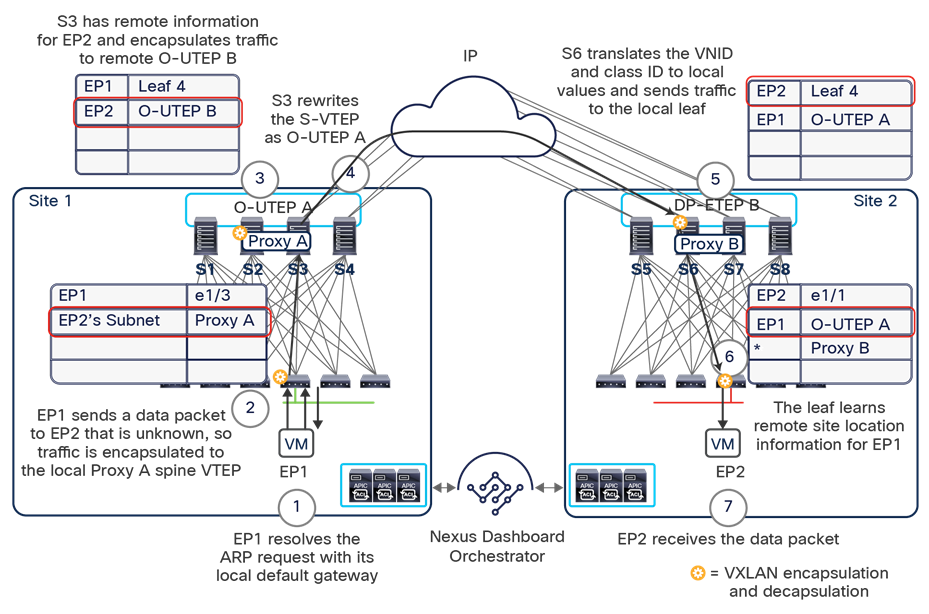
Layer 3 multicast forwarding across separate Cisco ACI fabrics
Cisco ACI Release 4.0(2) and Cisco Multi-Site Orchestrator Release 2.0(2) introduced support for TRM across Cisco ACI fabrics that are part of the same Cisco ACI Multi-Site domain. This essentially implies that Layer 3 multicast flows between source(s) and receiver(s) connected to different Cisco ACI fabrics can be forwarded as VXLAN-encapsulated traffic through the ISN, similarly to how was discussed in the previous sections for Layer 2 and Layer 3 unicast communication, removing the need to deploy a multicast-enabled backbone network (Figure 78).
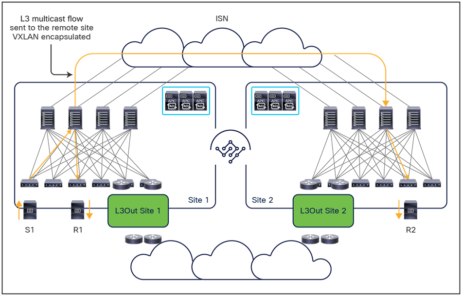
Layer 3 multicast support with Cisco ACI Multi-Site (from Cisco ACI Release 4.0(2))
Before describing how the forwarding across sites is enabled, both at the control and data plane levels, it is important to highlight some design and deployment considerations associated to this model:
● As with a single-fabric deployment, Layer 3 multicast forwarding is only supported when deploying second-generation leaf devices (Cisco Nexus 9300 EX models and newer).
● Just as with a single site, both PIM ASM and SSM are supported with TRM. Multicast source(s) and receiver(s) can be deployed inside the same site, across sites and also externally to the Cisco ACI fabrics (all combinations are fully supported). For what concerns the use of rendezvous points (RPs), required for PIM ASM deployments, RPs support internal to the Cisco ACI fabric is introduced for Multi-Site from Cisco ACI Release 5.0(1) and Cisco Multi-Site Orchestrator Release 3.0(1). For earlier ACI releases only RPs external to the Cisco ACI fabrics can be used for Multi-Site Layer 3 multicast deployments.
● Multicast routing with Cisco ACI is supported with an “always route” approach whereby TTL decrement is applied to the traffic twice (on the ingress and egress leaf nodes) even if the source and the receivers are part of the same IP subnet. It is worth noticing how intra-subnet multicast forwarding could also be achieved with Cisco ACI without enabling multicast routing and just handling those flows as Layer 2 multicast communication. However, those two behaviors are mutually exclusive and once multicast routing is enabled for a bridge domain, the “always route” approach will be the one in use.
● Multicast routing traffic is not subject to any policy enforcement, both intra- and intersite, so no contracts are required between the source’s EPG and the receivers’ EPGs to allow successful traffic forwarding.
● From a configuration perspective, multicast routing must be enabled at the VRF level on Cisco Nexus Dashboard Orchestrator, and this would result in the allocation of a GIPo multicast address to the VRF. A different set of GIPo addresses are reserved for the VRFs when compared to the GIPo addresses associated to the bridge domains (and used to forward BUM traffic inside the fabric).
● Once multicast routing is enabled on a given VRF, it is then required to enable it also for the individual bridge domains with Layer 3 multicast source(s) or receiver(s). Notice that those bridge domains may or may not be stretched across the sites. The solution should work in either case (the source bridge domain in one site and the receiver bridge domain in another site, stretched or non-stretched).
● When traffic originates from a source in a site and is forwarded to remote sites through the ISN, the proper translation entries must be created on the spines (for the VRF VNIDs and the EPG class-IDs), as already discussed for the unicast-communication use cases. In addition, if the source bridge domain is not stretched across sites, it is also required to configure the source IP subnet on the leaf nodes of the remote sites, to ensure a successful Reverse Path Forwarding (RPF) check when multicast traffic is received. In order to avoid having to create this configuration for all the EPGs and/or bridge domains that are Layer 3 multicast enabled, but only for the ones with sources connected, the user must explicitly indicate on Cisco Nexus Dashboard Orchestrator what are the EPGs containing multicast sources.
Support of fabric RP in a Multi-Site domain
Before looking into the details of TRM control and data plane behavior, it is worth to describe the new functionality introduced with Cisco ACI Release 5.0(1) and Cisco Multi-Site Orchestrator Release 3.0(1) that allows to configure multiple anycast RP nodes inside the fabrics part of the same Multi-Site domain.
Previous to those software release, the only option to provide a redundant RP functionality for fabrics that are part of a Multi-Site domain was to deploy anycast RP nodes in the external network domain, as shown in Figure 79.
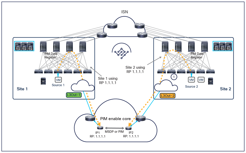
Anycast RP deployment in the external Layer 3 network
When sources connected in different ACI fabrics start generating multicast streams, PIM Data Register messages are sent from the First-Hop Routers (FHRs) where the sources are connected toward RP nodes deployed in the external Layer 3 network. Depending on the specific sites where the sources are located, those PIM messages may be received by different RP nodes, since they all share the same Anycast-RP address (this is the basic concept as in anycast RP providing a redundant RP deployment). It is therefore necessary to deploy an additional control plane between the various RP nodes to synchronize between them information about the active sources. A couple of options are typically deployed for this control plane: Multicast Source Discovery Protocol (MSDP) or Anycast-RP PIM (RFC 4610).
Support for fabric RP in a Multi-Site deployment allows you to simplify the deployment of a redundant RP functionality on multiple ACI leaf nodes belonging to different fabrics (Figure 80).
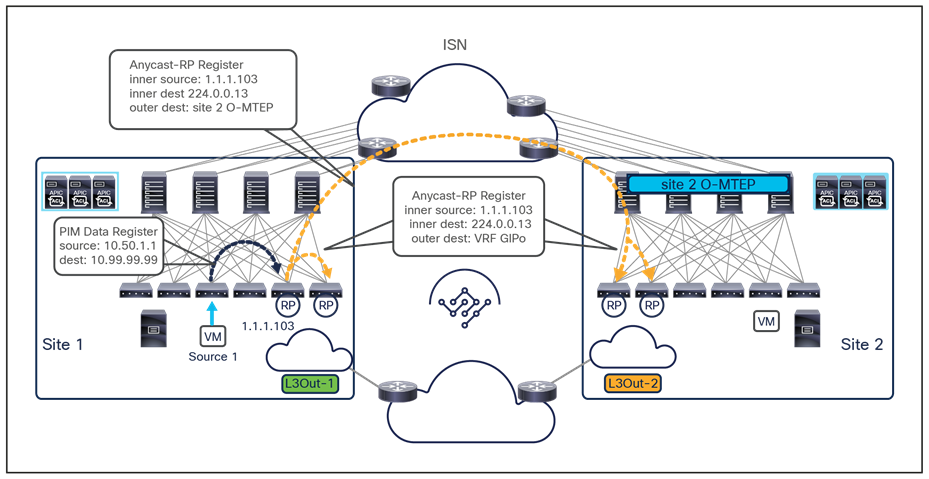
Use of fabric RP in a Multi-Site deployment
The Anycast-RP address is enabled on a set of border leaf nodes deployed inside each fabric. This means that, from the point of view of the external Layer 3 networks, multiple Anycast-RP nodes are seen as reachable via the L3Out connections deployed in each site. In the specific example shown above, when a source connected to an ACI leaf node in site 1 generates a multicast stream, the FHR device generates a PIM Data Register message and forwards it to one of the BL nodes available in the local site.
The specific BL node receiving such a message is then responsible to generate an Anycast-RP Register message (destined to the specific multicast group 224.0.0.13), which is forwarded inside the local fabric as VXLAN traffic destined to the VRF GIPo multicast address (each VRF usually gets assigned a dedicated GIPo address). This ensures that all the other local BL nodes configured as RPs receive the information; additionally, the specific spine that is elected as designated forwarder for traffic associated to the VRF GIPo replicates the Anycast-RP Register toward all the remote sites where the VRF has been stretched. This also allows the remote RP nodes to receive information about the source that got activated.
From a configuration perspective, the Anycast-RP address is configured on NDO associated to a specific VRF. It is then required to enable PIM on at least an L3Out per site (associated to that same VRF) to ensure that the RP address gets activated on the BL nodes that are part of those L3Outs.
Note: The definition of an L3Out in every site (where the corresponding VRF is defined) is mandatory for enabling the fabric RP functionality, even for deployments where the multicast sources and receivers are only connected to the fabric and there are no requirements to send or receive multicast streams to or from the external network connected to that L3Out.
Let’s now look at how the use of fabric RP allows you to deliver Layer 3 multicast streams between source and receivers that can be connected inside the ACI fabrics part of the Multi-Site domain, or in the external Layer 3 network infrastructure.
TRM control and data plane considerations
A set of functionalities (IGMP snooping, COOP, PIM) work together within Cisco ACI for the creation of proper (*,G) and (S,G) state in the ACI leaf nodes. Figure 81 shows those functionalities in action in a PIM-ASM scenario with the use of Anycast-RP nodes deployed across sites and when a source is activated in site 1, whereas receivers are connected in site 2 and in the external network.
Note: The use of the fabric RP configuration is recommended because it is operationally simpler. For more information on control and data plane behavior when deploying an RP external to the ACI fabric, please refer to Appendix A.
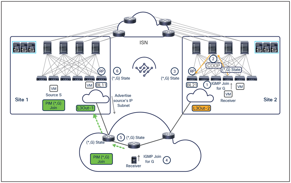
Control plane activity when internal and external receivers join multicast group G
● The receiver in site 2 originates an IGMP-Join for declaring its interest in receiving multicast traffic for a specific group G.
● The IGMP-Join is received by the Cisco ACI leaf node where the receiver is connected (Last-Hop Router [LHR]). The LHR registers the interest of a locally connected receiver (creating a (*,G) local entry) and generates a COOP message to the spines to provide the same information.
● The spines register the interest of the receiver for group G and generates a COOP notification to the local Border Leaf (BL) node that is configured as a fabric RP to communicate this information. A (*,G) local entry is created on the BL node.
● A receiver is connected in the external Layer 3 network and sends an IGMP-Join message for the same multicast group G.
● The LHR receives the message, creates a local (*,G) state, and sends a (*,G) PIM-Join message toward the RP. Since routes to the RPs are advertised in the external network from both ACI fabrics, the best path toward the RP is solely selected based on routing information.
● In the specific example in Figure 81, the RP BL node in site 1 receives the (*,G) PIM-Join message from the directly connected external router and creates a local (*,G) state.
Figure 82 shows the control plane activity happening once a source is connected in site 1 and starts streaming traffic for the multicast group G.
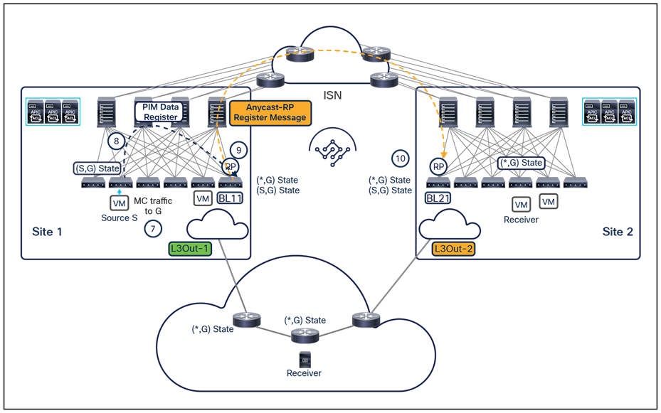
Control plane activity when an internal source starts streaming traffic to multicast group G
● A multicast source S is connected in site 1 and starts streaming traffic destined to group G.
● The first-hop leaf node (FHR) where the source is connected creates the (S,G) local state and sends a PIM data register message toward the RP. PIM Data Register packets are unicast packets with PIM protocol number 103 set in the IP header that will be forwarded through the Cisco ACI fabric toward the local border leaf node configured as RP.
● The RP creates a local (S,G) state and generates an anycast-RP register message that is forwarded across sites, as previously described in Figure 82.
● The RP in the remote site receives the message and creates a local (S.G) state.
At this point, data-plane forwarding for the multicast stream can start, as shown in Figure 83, below.
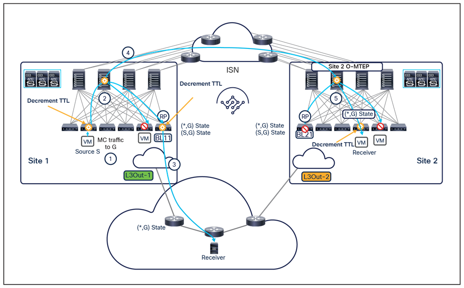
Data-plane forwarding of the multicast stream toward remote and external receivers
● The source S starts sending a multicast stream destined to group G.
● The FHR decrements the TTL in the packets, and VXLAN encapsulates them. The destination address used in the external IP header is the multicast group (GIPo) associated to the VRF. The packet is replicated inside the fabric and reaches all the spines and all the leaf nodes where the VRF has been deployed, including the BL11 node.
● BL11 decapsulates the traffic, decrements TTL, and forwards the stream toward the external network to reach the external receiver that previously joined the group.
● In parallel with the activity described at step 3 above, the specific spine node that has been elected as the designated forwarder for the VRF starts ingress-replicating the stream toward all the remote sites where the VRF has been stretched. The external destination IP address for the VXLAN-encapsulated packets is always the O-MTEP address of the remote sites.
● One of the spines in the remote site receives the packet and forwards it inside the fabric after changing the destination IP address to be the local VRF GIPo. The packet reaches all the leaf nodes where the VRF has been deployed and is then forwarded to directly connected receivers that have previously joined that group.
● Note: The multicast traffic sent to a particular group and originated from a source in a specific VRF is replicated to all the remote sites where that VRF has been stretched. As described above, the receiving spines will then forward the traffic inside the fabric if receivers interested in that group. If no receivers have been discovered, the spines will instead drop the traffic.
Specific considerations apply for the scenario shown in Figure 84, where the source is connected to the external network and the receivers are instead connected in different ACI fabrics that are part of the Multi-Site domain.
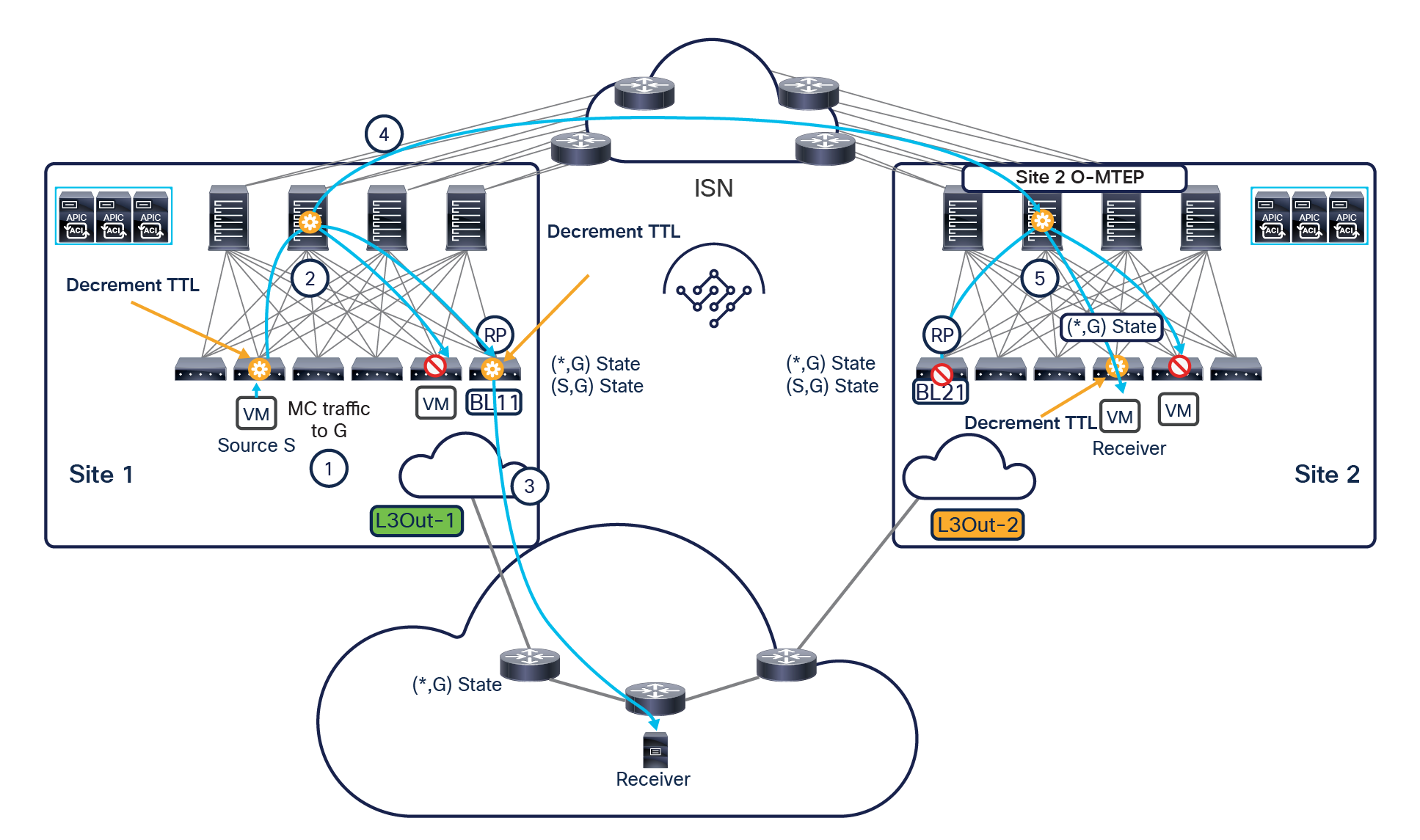
Control plane activity when internal receivers join multicast group G
The control plane activity, shown in Figure 84, when the internal receivers join a specific multicast group G, is quite similar to that previously shown in Figure 81 and ensures that the RPs deployed in each fabric can properly create a local (*,G) state.
Figure 85 highlights the control plane activity when an external source gets activated and starts streaming traffic to group G.
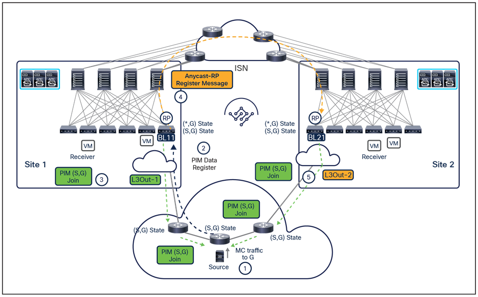
Control plane activity when an external source starts streaming traffic to multicast group G
● The external source starts streaming traffic to multicast group G.
● The FHR sends a PIM data register message toward the RP. As previously mentioned, specific routing information would steer the message toward the RP of a specific fabric (in this example, site 1).
● The BL11 in site 1 functioning as RP receives the message, creates a local (S,G) state, and sends a (S,G) PIM-Join toward the FHR. This allows you to build an (S,G) state on all the L3 routers between BL11 and the FHR.
● In parallel to the activity at step 3, BL 11 also generates an anycast-RP register message to be sent to other local RPs inside the fabric (if present) and to the RPs in the remote sites.
● When the RP on BL21 in site 2 receives the message, it locally creates an (S,G) state and sends (S,G) PIM-Join messages toward the FHR where the source is connected. This is the indication for the FHR devices that G streams received from the source should be replicated in both directions, toward site 1 and site 2.
After the control plane activities are completed, data forwarding for the multicast stream can occur, as highlighted in Figure 86.
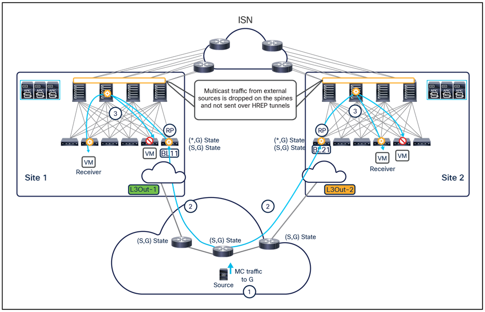
Data-plane forwarding of the multicast stream toward internal receivers
● The source starts streaming traffic for multicast group G.
● The FHR replicates the stream toward both fabrics because of the previously received (S,G) PIM-Join messages.
● When the BL nodes in each fabric receive the stream, they encapsulate in VXLAN frames destined to the VRF GIPo. This ensures that the traffic can be distributed inside each fabric and reach the internal receivers.
As shown in Figure 86, the spine nodes are programmed not to forward the multicast stream toward remote sites. This is done in order to avoid the possibility that remote internal receivers may receive duplicate streams. As a consequence of this behavior, the presence of an active local L3Out connection is mandatory for receivers in a given fabric to be able to get the multicast stream originated from an external source.
Note: The same data-path behavior shown in figures 83 and 86 applies when deploying PIM SSM. The only difference is that in the SSM case there is no need to define the external RP. The receivers, in fact, use IGMPv3 in the SSM scenario to declare their interest in receiving the multicast stream from a specific multicast source, and this leads to the creation of a multicast tree directly between the receiver and the source.
Multicast data plane traffic filtering
Prior to Cisco ACI Release 5.0(1), ACI only supported control plane filtering options for multicast traffic, through the configuration of IGMP report filters, PIM Join prune filters, and RP filters.
The multicast traffic filtering features in Cisco ACI Release 5.0(1) introduce support for filtering multicast traffic in the data plane. This data-plane filtering is controlled by a user-defined route-map configuration that can be configured directly on APIC (for single-fabric deployments) and also on MSO (from Cisco Multi-Site Orchestrator Release 3.0(1)) for Multi-Site deployments.
The data plane filtering is applied at the bridge domain level and allows you to filter:
● Traffic sourced by a specific source (or set of sources) and destined to all the multicast groups or just to a specific range. The set of sources and the multicast range are configured in the specific route-map applied to the bridge domain.
● Traffic received by a specific receiver (or set of receivers). The user can also specify the source (or set of sources) originating those streams and the multicast group range, still playing with the corresponding fields of the route-map applied to the bridge domain where the receivers are connected.
Figure 87 shows source filtering in action.
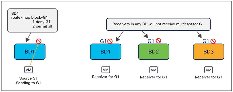
Data plane source multicast filtering
In this specific case, a route-map has been applied to BD1 (where the source S1 is connected) specifying to drop the multicast traffic generated by S1 and destined to the specific group G1. The end result is that receivers that have joined the group G1 (by performing the control plane activity discussed in the previous section) won’t be able to receive the multicast stream. Notice how this applies also to a receiver that is connected in the same bridge domain of the source, independently from the fact that the source and receivers are connected to the same ACI leaf or to different leaf nodes.
Figure 88 highlights the functional behavior when data plane filtering is applied on the bridge domain of the receivers.
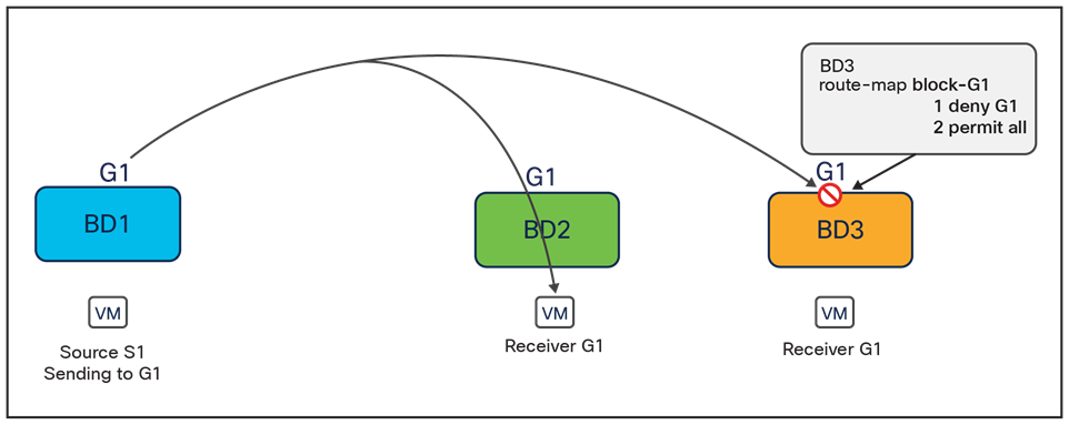
Data plane receiver multicast filtering
In this example, the traffic sourced from S1 and destined to G1 is forwarded (intra-fabric or across sites) to reach the leaf node where the receivers are connected. At that point, applying data plane filtering on BD3 ensures that receivers connected to that bridge domain won’t be able to get the stream, whereas receivers connected to different bridge domains will do so.
The use of route-maps allows greater flexibility in defining how to filter multicast traffic when compared to the use of control plane filtering, and this allows you to fulfill more complex use cases. However, as of Cisco ACI Release 5.0(1), the following are some of the restrictions of data plane multicast filtering:
● Supported only for IPv4 multicast traffic
◦ Multicast filtering is done at the BD level and applies to all EPGs within the BD. As such, you cannot configure different filtering policies for different EPGs within the same BD. If you need to apply filtering more granularly at the EPG level, you must configure the EPGs in separate BDs.
● Multicast filtering is intended to be used for Any-Source Multicast (ASM) ranges only. Source-Specific Multicast (SSM) is not supported for source filtering and is supported only for receiver filtering.
For more information on how to configure data plane multicast filtering on APIC and NDO, please refer to the documents below:
Integration of Cisco ACI Multi-Pod and Multi-Site
Cisco ACI Release 3.2(1) introduces the support for a “hierarchical” design allowing combination of the Cisco ACI Multi-Pod and Cisco ACI Multi-Site architectures. There are two main use cases where this integration becomes beneficial (Figure 89):
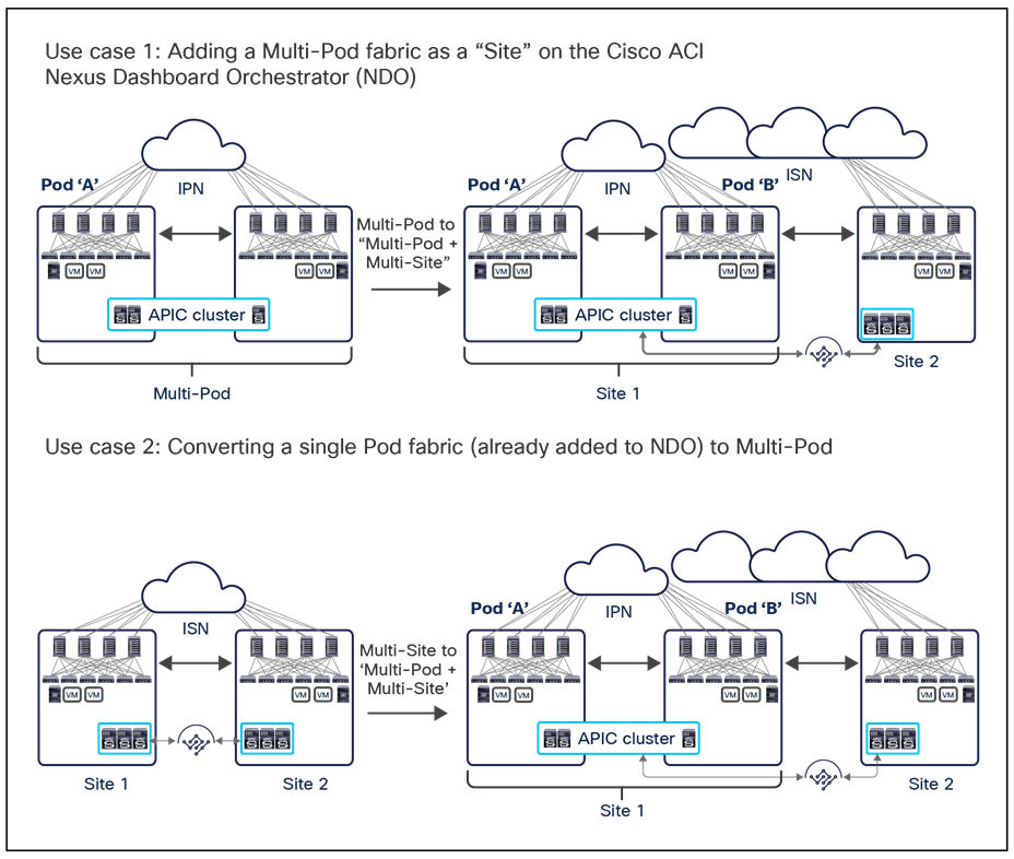
Use cases for integrating Cisco ACI Multi-Pod and Cisco ACI Multi-Site
1. In the first scenario, a Cisco ACI Multi-Pod fabric is already deployed in production and one (or more) additional fabrics are connected to it by leveraging Cisco ACI Multi-Site. This is a pretty typical use case for customers who deployed Cisco ACI Multi-Pod to interconnect active/active data centers (often deployed in the same geographical location or in close proximity to each other), and they want then to connect the Multi-Pod fabric to a remote data center acting as a disaster-recovery site.
Note: In this first use case, when an already deployed Multi-Pod fabric gets added as a “site” to the Cisco Nexus Dashboard Orchestrator, NDO will automatically pull information from the APIC about the already deployed configuration in the “infra” tenant for connecting the spines to the IPN (interfaces, IP addresses, OSPF configurations, etc.).
2. In the second scenario, Cisco ACI Multi-Site is in production to interconnect single-Pod fabrics, but there is a need (for example, for scalability reasons in terms of total number of supported leaf nodes) to convert one or more of the single-Pod fabrics to Multi-Pod.
As shown above, no matter the use case under consideration, the end result is a “hierarchical” architecture combining Cisco ACI Multi-Pod and Multi-Site. The following sections will provide more technical and design considerations for this deployment option.
Connectivity between pods and sites
The Inter-Pod Network (IPN) has specific requirements (PIM-Bidir support, DHCP-Relay support, and increased MTU) to connect the different pods that are part of the same Multi-Pod fabric. The Intersite Network (ISN) is a simpler routed infrastructure required to interconnect the different fabrics (only requiring support for increased MTU). When integrating Cisco ACI Multi-Pod with Cisco ACI Multi-Site, there are two main deployment options, each one characterized by specific design considerations.
● Single network infrastructure offering both IPN and ISN connectivity (Figure 90)
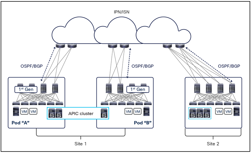
Single network infrastructure offering both IPN and ISN connectivity
The first important thing to notice in the figure above is that first-generation spine models (like Cisco Nexus 9336PQs or modular chassis with first-generation line cards) while supported in the Cisco ACI Multi-Pod fabric design, cannot be used when combining Cisco ACI Multi-Pod and Multi-Site. Only second-generation Cisco Nexus 9000 spine switches (Cisco Nexus 9332C/9364C or Cisco Nexus 9500 modular models with EX/FX line cards or newer) must be connected to the external network providing communication with remote pods/sites. Also, at least one second-generation spine (two for redundancy) must be deployed in each pod of the Multi-Pod fabric when this is added as a site in a Multi-Site domain.
Note: For specific non modular spine models, as the 9332C and 9364C platforms, it is also possible to use the native 10G interfaces (SFP based) to connect to the ISN devices.
If the same network is used for both IPN and ISN connectivity services, it is quite natural to use a common set of links between the spines and the first-hop IPN/ISN routers for both types of east-west traffic. The number of physical links and/or their capacity can then be scaled up or down depending on the estimated amount of east-west communication that is required.
For each pod, all the physical links connecting the spines to the IPN/ISN are configured as part of the same “infra” L3Out logical connection, and OSPF peering can then be established between the spines and the IPN/ISN first-hop routers.
Note: Additional considerations are required when deploying GOLF L3Outs for north-south communication, as discussed in greater detail in the “Multi-Site and GOLF L3Out connections” section.
The “underlay” routes learned on the IPN/ISN first-hop routers can then be redistributed into a different control plane protocol inside the IPN/ISN network.
● Separate network infrastructures for IPN and ISN connectivity (Figure 91)
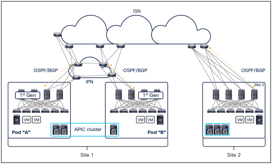
Separate network infrastructures for IPN and ISN connectivity
It is quite common that separate network infrastructures are deployed and used for Cisco ACI Multi-Pod and Multi-Site communication (that is, the IPN and the ISN are physically two separate networks). This is the case since Multi-Pod is often deployed to interconnect Cisco ACI networks that are deployed in the same physical data center locations (Pods represent rooms or halls in the same data center) or in close proximity (Pods represent separate data centers in the same campus or metro area). This implies that dedicated dark fiber or Dense Wavelength Division Multiplexing (DWDM) circuits are frequently used to interconnect the pods that are part of the same Multi-Pod fabric. Multi-Site, on the other side, is often positioned to provide connectivity between Cisco ACI fabrics deployed at larger geographical distances; therefore, separate WAN networks are used to provide the ISN services.
Despite the use of separate IPN and ISN infrastructures, it is required for the spines to use a common set of links to establish OSPF or BGP peering with the external routers and handle both Multi-Pod and Multi-Site east-west traffic flows. This means that the IPN and ISN network must be connected with each other, and it is not possible to use separate connections between the spines and the IPN/ISN to handle the two types of communication (as shown in Figure 92).
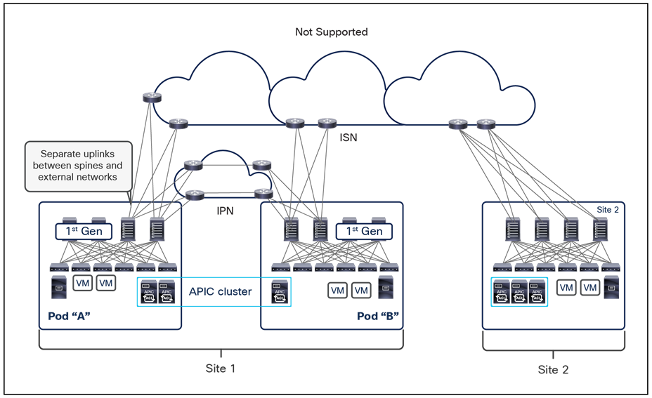
Use of separate uplinks between spines and external networks
The use of MP-BGP EVPN is a common functionality for both Cisco ACI Multi-Pod and Multi-Site architectures. When combining the two designs together, a hierarchical peering model is introduced to minimize the amount of EVPN adjacencies created between the spine nodes part of separate sites.
In order to support this hierarchical peering model, each spine node can support one of these two roles:
● MP-BGP EVPN Speaker: All the spine nodes configured as speakers establish EVPN adjacencies with the speakers deployed in remote sites. It is worth noticing that the speaker’s role must be explicitly assigned by the user to the spines leveraging Cisco Nexus Dashboard Orchestrator (through the GUI or via REST API calls).
● MP-BGP EVPN Forwarder: All the spines that are not explicitly configured as speakers become forwarders. The forwarders establish EVPN adjacencies with all the speakers deployed in the same fabric.
Note: The role of BGP Speakers can only be enabled for Multi-Site-capable spines (that is, second-generation hardware models – EX or newer). The implicit forwarder roles can instead be assigned to all the spines, also first-generation ones.
Figure 93, below, highlights the EVPN adjacencies established in a Cisco ACI Multi-Pod plus Multi-Site deployment model.
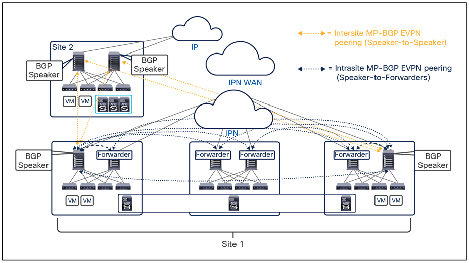
Hierarchical MP-BGP EVPN peering
Note: An MP-BGP EVPN adjacency is also established between the two speakers deployed in separate pods of the same Multi-Pod fabric.
As shown above, for the sake of redundancy it is always recommended to deploy two MP-BGP EVPN Speakers in each site: depending on whether the site is deployed as single pod or Multi-Pod, the two Speakers would be part of the same pod (for example, site 2 in Figure 93) or deployed across pods (for example, site 1 in the same Figure 93).
The EVPN adjacencies between the speakers and the forwarders ensure that the forwarders can learn endpoint information received by the local speakers from the speaker spines in the remote sites, keeping low the total required number of geographical EVPN adjacencies.
Note: The same loopback interface can be configured on each spine node to establish both the EVPN peerings with spines of other pods that are part of the same Multi-Pod fabric and with the spines in remote sites. This applies in both the use cases previously described where an existing Multi-Pod fabric is added to a Multi-Site domain or where a single pod fabric that is already part of a Multi-Site domain is expanded to become a Multi-Pod fabric. From a TEP configuration perspective (i.e., the IP address used to receive VXLAN encapsulated traffic), it is recommended to deploy unique addresses to be sued for Multi-Pod and Multi-Site traffic flows.
As previously discussed in the “Cisco ACI Multi-Site overlay data plane” section, different types of east-west communication can be established between sites, all leveraging the use of VXLAN data-plane encapsulation to simplify the configuration and functionality required by the intersite network. This remains valid when integrating Cisco ACI Multi-Pod and Multi-Site, with just a few additional design considerations discussed in the following sections.
Layer 2 and Layer 3 unicast communication
Assuming endpoint reachability information has been exchanged across sites, and assuming ARP exchange has also successfully completed, the leaf and spine nodes would have their Layer 2, Layer 3, and COOP tables properly populated to allow the establishment of intersite unicast traffic flows (Figure 94).
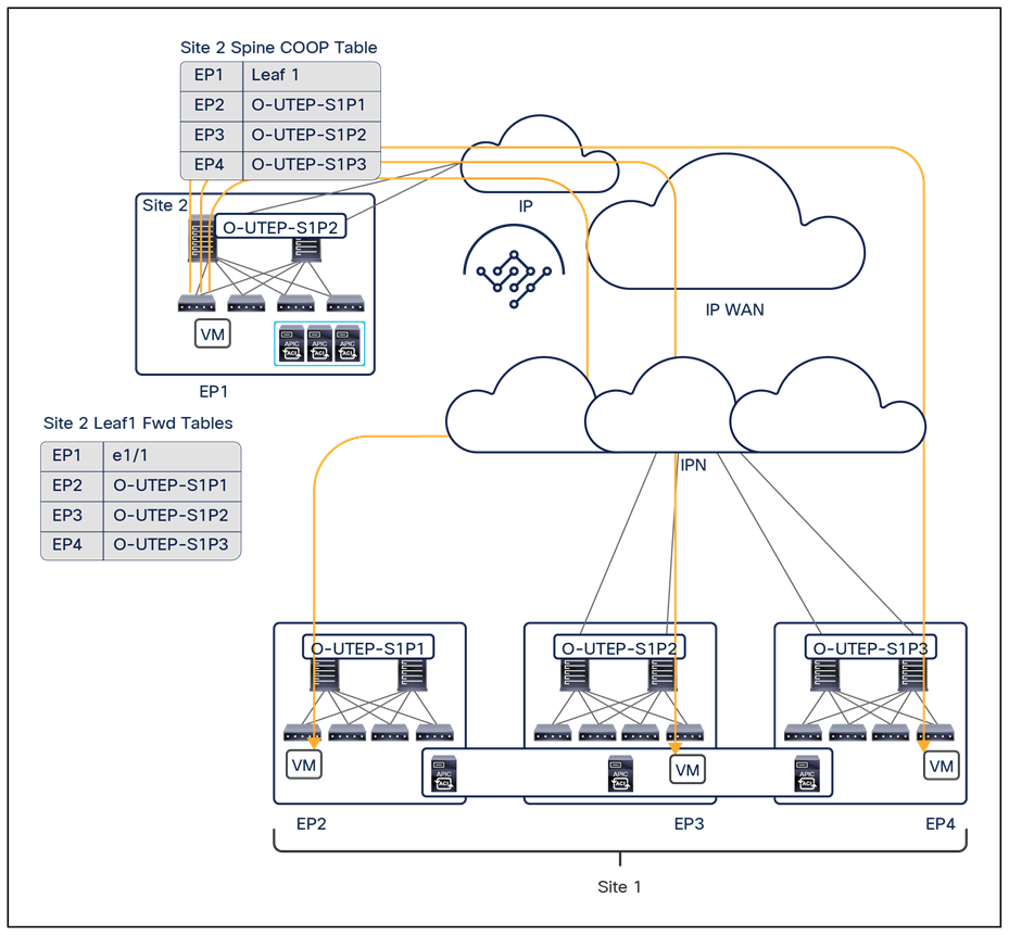
Unicast traffic ingressing a Multi-Pod fabric that is part of Cisco ACI Multi-Site
When integrating a Cisco ACI Multi-Pod fabric in a Multi-Site architecture, each pod will be assigned a unique Overlay Unicast TEP address (O-UTEP) to be associated to all the Multi-Site-capable spines deployed in that pod. This ensures that Layer 2 or Layer 3 traffic received from a remote site can be steered directly to the specific pod where the destination endpoint is connected.
Note: The Data-Plane TEP used for inter-Pod communication must be different from the O-UTEP address used for inter-fabric communication.
Figure 95 shows, instead, how Layer 2 BUM traffic can be sent from a remote site toward a Multi-Pod fabric deployed as a site.
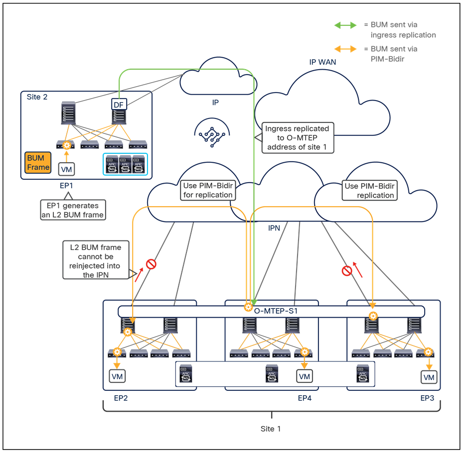
Layer 2 BUM traffic ingressing a Multi-Pod fabric that is part of Cisco ACI Multi-Site
Differently from the unicast scenario, a single Overlay Multicast TEP address is associated to all the Multi-Site-capable spines that are part of the same Multi-Pod fabric (that is, across all the deployed pods). This implies that ingress L2 BUM traffic can be delivered to the spines of any pod, solely based on routing information available in the external backbone network. The receiving spine would then have to perform two operations; it would have to:
● Forward the BUM traffic inside the pod along an FTAG tree associated to the bridge domain the traffic belongs to
● Forward the BUM traffic to the other pods through the IPN
When the spines in other pods receive the BUM traffic, they would then be able to forward it locally inside their pods while not being allowed to reinject the traffic into the IPN, to avoid traffic duplication.
Filtering TEP pool prefixes across sites
Based on what was previously discussed, it should now be clear how all the intersite data-plane communication happens leveraging the Overlay TEP addresses (unicast and multicast) as destinations. This implies that the TEP pool range originally assigned on APIC for the fabric bring-up plays no role in this intersite communication. However, the internal TEP pool is still advertised from the spines to the external network, mostly to allow the integration of Cisco ACI Multi-Pod and Multi-Site, as shown in Figure 96.
TEP pool advertisement out of each pod and filtering it out in the backbone
Communication between endpoints belonging to separate pods that are part of the same Multi-Pod fabric is established by creating VXLAN tunnels directly between the leaf nodes where the endpoints connect. This implies that the TEP pools must be exchanged between different pods that are part of the same fabric.
Between different fabrics, the exchange of TEP pool information not only is not required, but could actually create problems in scenarios such as the one shown above, where the same TEP pool (10.1.0.0/16) has been defined across separate sites. It is therefore a best-practice recommendation to ensure that the TEP Pool information is filtered to prevent injecting it into the backbone of the network.
Similarly, PIM Bidir is used to forward Layer 2 BUM traffic between the pods. Since intersite BUM forwarding is done by leveraging ingress-replication, it is recommended to not enable PIM for those multicast groups in the backbone of the network interconnecting different sites, to prevent forwarding issues in scenarios where different Multi-Pod fabrics are part of the same Cisco ACI Multi-Site architecture.
Connectivity to the external Layer 3 domain
Connectivity for the VRF instances defined within a Cisco ACI fabric to the external Layer 3 network domain is achieved by the creation of logical connections called L3Out connections. The following two design options are available for the configuration of L3Out connectivity:
● L3Out connections defined on border leaf nodes
● EVPN-based L3Out connections (also known as the “GOLF” design option)
Figure 97 shows the L3Out connections defined on border leaf nodes that have been supported with ACI from the beginning.
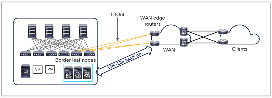
L3Out connections on border leaf nodes
This approach uses a VRF-Lite configuration to extend connectivity for each VRF instance toward the WAN edge routers. The data-plane VXLAN encapsulation used within the Cisco ACI fabric is terminated on the border leaf nodes before the traffic is sent toward the WAN edge routers. This approach allows also to support a “Shared L3Out” model, where a single L3Out (usually defined as part of the “common” Tenant configuration) can be used to provide external connectivity to bridge domains defined inside the fabric and belonging to different VRFs/Tenants.
Note: For more information about border leaf L3Out connections, see the document at the following link: https://www.cisco.com/c/en/us/solutions/collateral/data-center-virtualization/application-centric-infrastructure/guide-c07-743150.html
Figure 98 shows the SR-MPLS/MPLS handoff functionality offer on border leaf nodes from Cisco ACI Release 5.0(1).
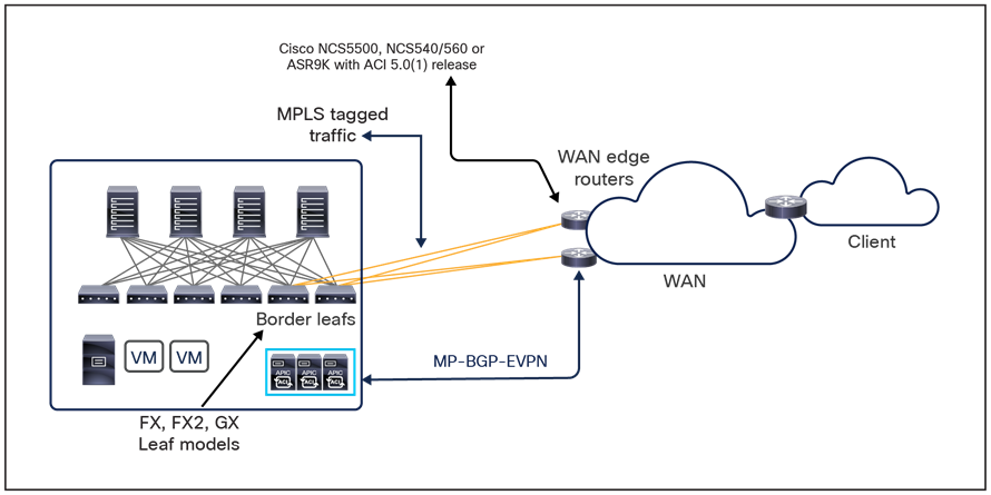
SR-MPLS/MPLS hand-off on border leaf nodes
With this approach, the per-VRF routing peering characterizing the traditional VRF-lite model is replaced with the establishment of a single MP-BGP EVPN control plane between the border leaf nodes and the DC-PE routers. This single control plane allows you to exchange control plane information for all the VRFs defined inside the fabric that require connectivity with the external network domain. From a data-plane perspective, MPLS tags would replace 802.1q tags to ensure logical isolation for Layer 3 communications belonging to different VRFs.
The provisioning of the SR-MPLS/MPLS handoff configuration on the BL nodes can be performed on APIC for single-fabric deployments, but it is also directly exposed on the Cisco Nexus Dashboard Orchestrator for fabrics that are part of a Multi-Site domain. This not only provides the capability of centrally provisioning north-south connectivity for all the fabrics that are part of the Multi-Site domain, but also to ensure that intersite Layer 3 communication can be handled via the external MPLS-enabled core and is not leveraging the native Multi-Site VXLAN data-path. As previously mentioned, when discussing intersite Layer 3 communication, using the L3Out path with SR-MPLS/MPLS handoff may be useful to be able to apply specific SR-MPLS TE policies to east-west traffic flows between ACI networks and also to allow WAN teams to leverage familiar tools for monitoring DC-to-DC communication.
If instead the desire is to deploy SR-MPLS handoff to simplify the peering with the external network to exchange multi-VRF routing information (that is, deploying a single MO-BGP EVPN control plane rather than the routing protocol per VRF model typical of VRF-lite deployments) and establish north-south connectivity, while continuing to leverage VXLAN across the ISN for east-west communication, NDO 4.0(2) introduces the capability of treating SR-MPLS L3Out handoffs the same way as traditional IP-based L3Out handoffs. This will be clarified in the following sections.
Note: For more information on the deployment of SR-MPLS/MPLS handoff, please refer to the document below: https://www.cisco.com/c/en/us/td/docs/dcn/ndo/3x/configuration/cisco-nexus-dashboard-orchestrator-configuration-guide-aci-371/ndo-configuration-aci-use-case-sr-mpls-37x.html
Figure 99 shows the EVPN-based L3Out, or GOLF, design option. The GOLF approach was originally introduced to scale up the number of VRF instances to be connected to the external Layer 3 network domain (1000 VRF instances have been supported from the launch of GOLF integration with Cisco ACI).
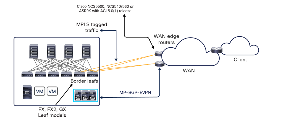
With GOLF, the connectivity to the WAN edge routers is no longer provided by the border leaf nodes, but these routers connect now (directly or indirectly) to the spine nodes. Similarly as the SR-MPLS handoff just discussed, MP-BGP EVPN control plane allows to exchange routes for all the ACI VRFs requiring external connectivity, OpFlex control plane automates the fabric facing VRF configuration on the GOLF router and finally VXLAN data plane enables north-south communication.
Note: For more information on GOLF, see the documents at the following links: https://www.cisco.com/c/en/us/solutions/collateral/data-center-virtualization/application-centric-infrastructure/white-paper-c11-736899.html
The following two sections discuss in detail the integration of border leaf L3Outs (IP-based and SR-MPLS handoffs) with the Cisco ACI Multi-Site architecture. The deployment of GOLF L3Out is not recommended anymore for new production use cases (while remaining fully supported for existing deployments), so the related content has been moved to Appendix C of this paper.
Cisco ACI Multi-Site and L3Out connections on border leaf nodes
From the initial release of the Cisco ACI Multi-Site architecture, the two scenarios shown in Figure 100 are fully supported when deploying IP-based L3Out connections on border leaf nodes.
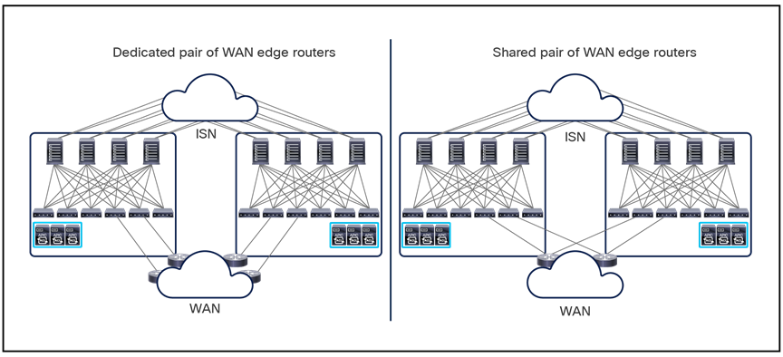
Dedicated or shared pairs of WAN edge routers
Note: Starting from NDO 4.0(2), the same models are also supported with SR-MPLS L3Out handoffs.
In the scenario on the left, most common for the majority of Multi-Site deployments, different Cisco ACI fabrics map to separate physical data center locations. In this case, a dedicated pair of WAN edge routers are commonly used to connect each fabric to the external WAN network. In the scenario on the right, the Cisco ACI Multi-Site design is used to interconnect fabrics deployed in the same geographical location, and a shared pair of WAN edge routers is commonly used to provide connectivity to the WAN. In both cases, and before Cisco ACI Release 4.2(1), you always must deploy a separate L3Out logical connection in each site (that is, on each APIC cluster). In other words, endpoints deployed in a given site can communicate with the external network domain only through a local L3Out connection, as highlighted below.
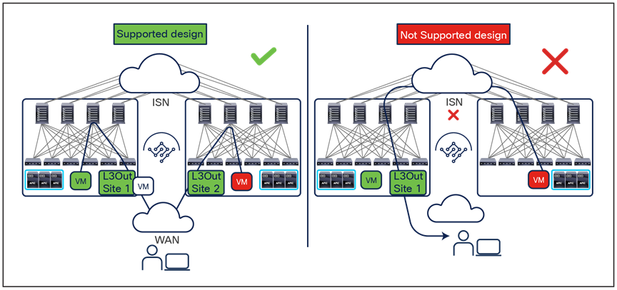
Cisco ACI Multi-Site and L3Out connectivity (pre–Release 4.2(1))
Cisco ACI Release 4.2(1) introduces a new functionality named “Intersite” L3Out, removing the restriction shown above. For more details and use cases for Intersite L3Out please refer to the “Introducing the Intersite L3Out Functionality (ACI 4.2(1) Release and onwards)” section. All the considerations made in the remaining part of this section assume the deployment of at least a local L3Out per site.
The L3Out objects defined in each APIC domain are exposed to the Cisco Nexus Dashboard Orchestrator to be associated to External-EPGs that can be defined directly on the NDO, as explained later in this section.
Figure 101, above, showed the use of two separate network infrastructures: a Layer 3 intersite network (ISN) to be used for all the east-west communication between endpoints connected to different fabrics, and a WAN network used to establish north-south connectivity to remote clients. These are common deployment models. However, you can also use the same WAN infrastructure for both purposes, as shown in Figure 102.
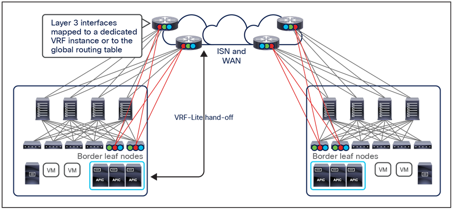
Common Layer 3 infrastructure for east-west and north-south traffic
In this scenario the same pair of WAN edge routers serve two purposes:
● Connect to the border leaf nodes to allow external connectivity to the VRF instances deployed within each Cisco ACI fabric (north-south traffic flows): VRF-lite is used to exchange routing information for each VRF instance when leveraging IP-based L3Outs, whereas MP-BGP EVPN is used for SR-MPLS L3Outs. In both cases, different VRF instances are commonly deployed on the WAN edge routers as well.
Note: The exception is the use case in which different Cisco ACI VRF instances connect to a common routing domain into the external WAN. In this scenario, only a shared VRF (which can even be the global routing table) needs to be defined on the WAN edge router (shared L3Out deployment option). This “Shared L3Out” model is supported with Cisco ACI Multi-Site starting from Cisco ACI Release 4.0(1).
● Connect to the spine nodes to provide routing support for VXLAN traffic that is exchanged across sites (east-west traffic flows): This communication can occur inside the WAN network either in a dedicated VRF instance (best-practice recommendation) or in the global routing table.
Figure 103 shows the sequence of steps required to provide external connectivity to endpoints connected to separate Cisco ACI fabrics in the specific scenario of IP-based L3Outs deployments. Notice that in this specific example the web endpoints belong to different bridge domains that are defined only locally in each specific site (that is, we can consider the Web EPGs being part of separate application stacks).
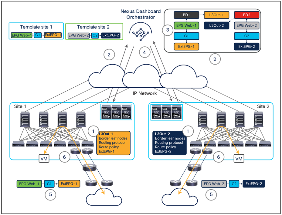
Multi-Site and IP-based L3Out connections on border leaf nodes
● The first step is to create the L3Out configuration to be used to connect the specific web bridge domains to the external Layer 3 domain. This step includes the definition of the border leaf nodes and their interfaces and the routing protocol used to peer with the external devices and is performed at the APIC level (hence separately for each site) and not in the Cisco Multi-Site Orchestrator. Starting from Cisco Multi-Site Orchestrator Release 2.2(1), it is also possible to create an L3Out object directly into the Orchestrator and then deploy it in one or more sites associated to the template where the L3Out was defined. However, the configuration of logical nodes, logical interfaces, etc., is still performed at the APIC level in each fabric. Also, the recommendation is not to configure an L3Out in a stretched template, but instead to define separate L3Outs objects in site-specific templates. Being able to clearly identify and differentiate the L3Outs of different sites provides, for example, better control on where to advertise internal BD subnets, as will be discussed in the “Introducing Intersite L3Out functionality (Cisco ACI Release 4.2(1) and onward)” section.
Note: An L3Out connection is always associated to a specific VRF instance. In the scenario described in this example, the creation of such a VRF stretched across sites should therefore be performed on the Orchestrator before the local creation of L3Outs is possible.
● The user can then define in NDO external EPG objects and associate them to each L3Out for configuring the specific connectivity requirements for internal EPGs.
● In Cisco Nexus Dashboard Orchestrator, you can define two templates with corresponding application network profiles specifying web EPGs that should have access to the external network domain using the specific L3Out connections already provisioned at each site. This is done by creating a specific contract in each template between the web EPG and the external EPG associated to the local L3Out. The created templates are then independently associated with the sites to which they should be pushed (in Figure 103, the first template is associated with site 1, the second with site 2).
Note: An alternative approach consists in creating a single external EPG (Ext-EPG) defined in a template mapped to both sites; this stretched Ext-EPG can then be mapped to each L3Out at the site level. Such an approach is useful when the L3Outs in both sites provide access to the same external network resources, because it allows you to define the Ext-EPG configuration (and its associated security policies) only once (Figure 104).
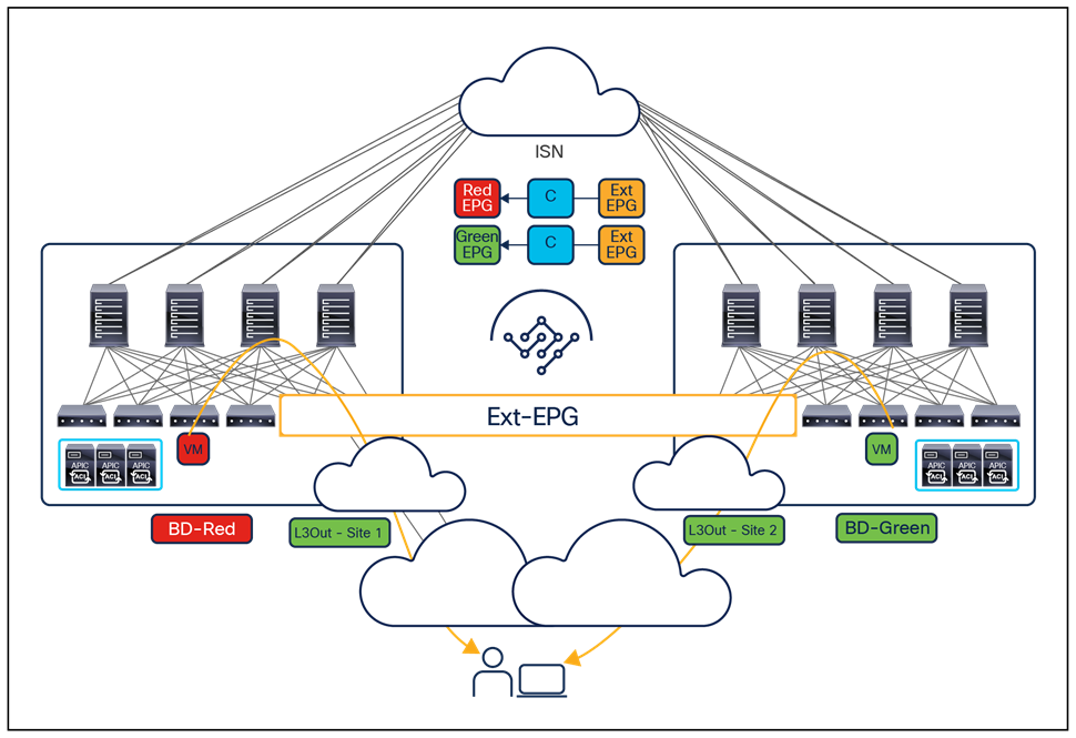
Use of a stretched external EPG (Ext-EPG)
● The template configuration is pushed to the respective sites.
● The configuration is therefore applied in each APIC domain to provide external connectivity to the endpoints that are part of the web EPGs defined at each site.
● Each site’s local L3Out connections are used for inbound and outbound connectivity.
The scenario just described is simple, because each web EPG (with the associated bridge domain and IP subnet) is uniquely defined at each site. As a consequence, inbound traffic originating from the WAN always will be steered to the specific site at which the web destination endpoint is located and flows always will traverse in a symmetric fashion the perimeter firewall that can be deployed between the WAN and each Cisco ACI site.
A different behavior may occur when the web EPG and the associated bridge domain are stretched across sites, as shown in Figure 105.
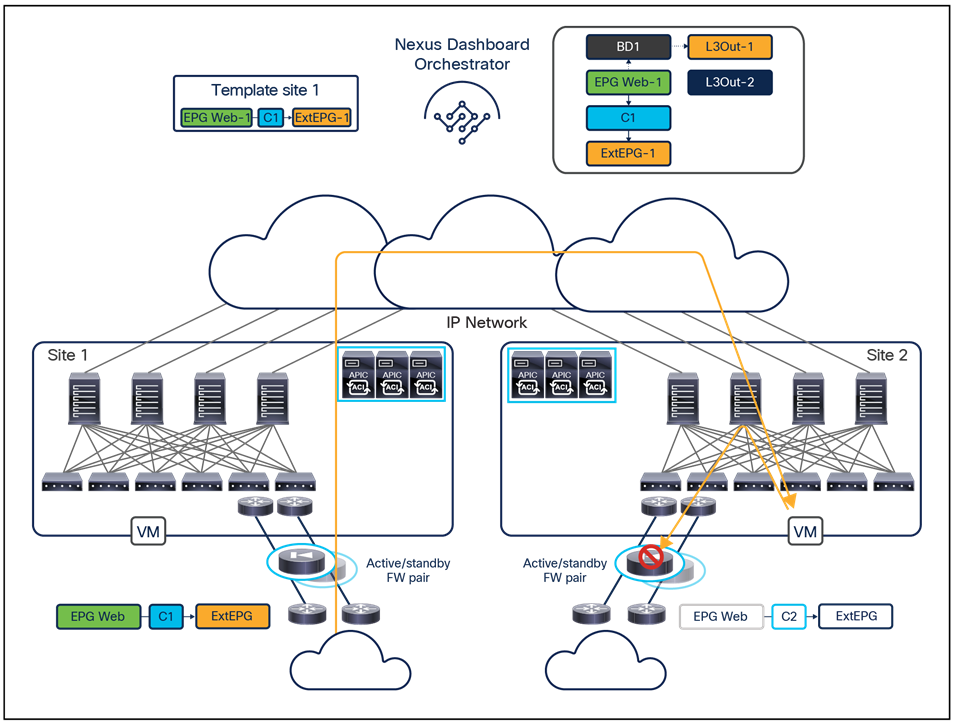
Multi-Site and traditional L3Out connections with a stretched bridge domain
In this case, a different L3Out connection is defined at each site, but the template created in Cisco Nexus Dashboard Orchestrator associates the same web EPG with both, because the web endpoints are connected to the bridge domain stretched across sites. Notice how, before Cisco ACI Release 4.2(1), it is here mandatory for the external EPG associated to both L3Outs to be a “stretched” object part of the same template associated to both sites. This is needed to ensure traffic can enter a given site (site 1 in Figure 105) and then be forwarded via the VXLAN tunnel toward a remote site where the destination endpoint is connected, since proper translation entries in the spine will be created in virtue of the fact that the external EPG is stretched. From Cisco ACI Release 4.2(1) it will be possible instead to have the Ext-EPG also deployed only locally in a site, as the establishment of a contract with an internal (or external) EPG in a remote site would lead to the creation of required translation entries in the spines (for more information please refer to the “Introducing the Intersite L3Out functionality (Cisco ACI Release 4.2(1) and onward)” section).
As a consequence, by default the same web IP prefix will be advertised from both sites toward the external Layer 3 network, and inbound traffic may be delivered to the border leaf nodes of site 1 even if the destination endpoint is connected in site 2. In that case, Cisco ACI Multi-Site will handle the delivery of the traffic to the endpoint via the ISN, but the return flow toward the WAN will use the local L3Out connection in site 2. This approach will cause traffic drops if a stateful firewall device (independent from the one deployed in site 1) is deployed to protect the perimeter of site 2.
A specific functionality, available from Cisco ACI Release 4.0(1), offers a “network centric” solution to this problem by providing support for more granular host-route advertisement out of L3Out connection on border leaf nodes.
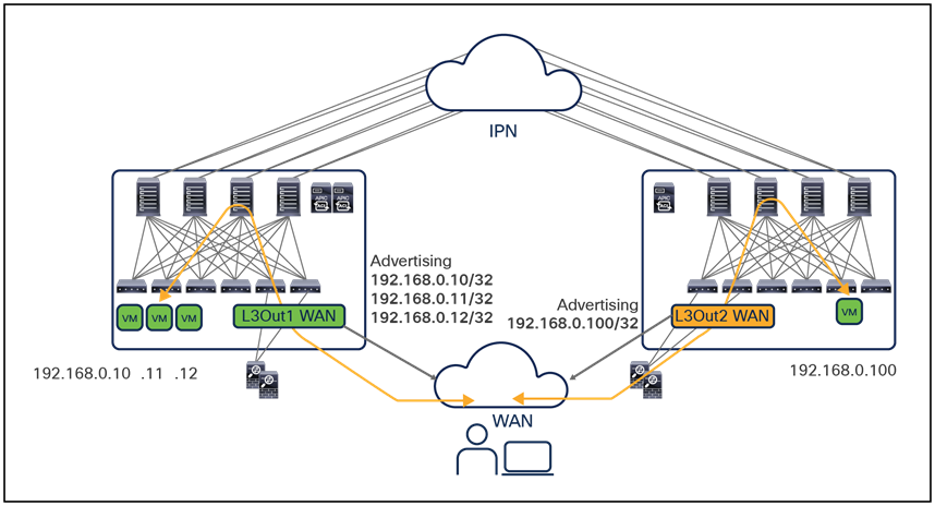
Optimized inbound/outbound traffic flows with host-route advertisement
Note: As of Cisco ACI Release 5.2(5) and NDO Release 4.0(2), host-route advertisement is not supported for SR-MPLS L3Out handoffs.
As shown in Figure 106, enabling host-route advertisement on the local L3Out connections can make the ingress and egress traffic flows symmetric, ensuring that the same stateful service is traversed for each communication between the external network and the internal EPG. Host-route advertisement can be enabled at the specific bridge-domain level, to ensure tight control of what host routes are advertised outside the fabric and mitigate scalability concerns.
Note: When injecting host-routes into the external network, it is important to ensure that those host routes are not received on the L3Out connections of remote sites and re-advertised inside those fabrics (as this may interfere with the native East-West communication across sites established via VXLAN data-plane). Depending on the specific routing protocol, used on the L3Out of each fabric and inside the backbone, this host-route filtering on the receiving L3Out happens automatically. In other cases, it is recommended to apply an ingress route-filtering to explicitly drop the received host-routes.
The support for host-route advertisement allows deployment of a specific design option where one specific ACI site is considered the “home site” for a given IP subnet. This essentially means that the large majority of endpoints belonging to that IP subnet are normally connected to that site, and only for specific reasons (such as business-continuance or disaster-recovery scenarios) may the endpoints be migrated to a separate site.
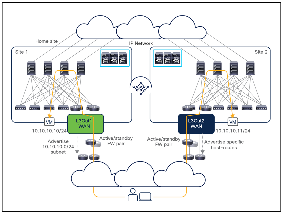
The behavior shown in Figure 107 can easily be achieved by defining a route-map associated to the L3Out of each site and used to specify what IP prefixes should be advertised toward the external network domain: in site 1, the route-map will match only the IP subnet prefix, whereas in site 2, it will match specific host-routes and also the IP subnet prefix but ensuring it is advertised out with a less preferable metric to site 1. As a result, the overall number of host routes that need to be injected is reduced, given that only the IP subnet information is required to steer inbound traffic toward the home site.
In scenarios in which host-route information cannot be advertised in the WAN (either because of scalability concerns or because host routes are not accepted in the WAN network), you still should consider exporting the host routes to the external router, because doing so opens other possible design options:
● Establishment of overlay tunnels directly from the external router to remote routers or directly between the external routers deployed in separate data-center locations (using Multiprotocol Label Switching [MPLS] over generic routing encapsulation [MPLSoGRE] or plain GRE tunneling) to avoid exposing the host routes to the WAN.
Note: Verify the specific GRE support on the external router in the specific platform documentation at Cisco.com.
● Integration with an SD-WAN solution (such as Cisco SD-WAN, for example), which also allows the establishment of a sort of overlay control plane across the WAN network so that granular routing information can be provided directly to the remote WAN edge routers.
◦ Use of Locator ID Separation Protocol (LISP) on the external router, to allow remote LISP routers to encapsulate the traffic to the correct site based on the registration of endpoint information in the LISP mapping server.
Introducing Intersite L3Out functionality (Cisco ACI Release 4.2(1)/MSO Release 2.2(1) and onward)
The behavior shown in Figure 101, above, which does not allow an endpoint deployed in a given site to communicate with resources external to the fabric via the L3Out connection deployed in a separate site, prevents the enablement of some important use cases.
L3Out connections are normally used not only to provide connectivity to the external network domain (WAN or Internet) but are often deployed also to establish connectivity with resources like mainframes, firewalls, load-balancers, etc., for which intersite communication is often required.
This is the main reason Cisco ACI Release 4.2(1)/MSO Release 2.2(1) introduces a new Intersite L3Out functionality, enabling the use cases depicted in Figure 108, below.
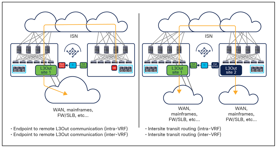
Use cases supported with Intersite L3Out functionality
As shown above, with Intersite L3Out endpoints connected to a specific site are able to communicate with “entities” (WAN, mainframes, service nodes, etc.) deployed in a separate site and reachable via that remote L3Out connection (both intra-VRF and inter-VRF). Additionally, transit routing can also be enabled across sites, also intra-VRF and inter-VRF and this represents important functionalities for the scenarios where a Multi-Site domain is deployed as a core network to interconnect different edge network domains.
Note: As previously mentioned, the behavior shown in Figure 108 can also be achieved with SR-MPLS L3Out handoffs but only starting with NDO Release 4.0(2).
Intersite L3Out guidelines and restrictions
The following are some restrictions to consider for Intersite L3Out at the time of writing of this document (that is, in the Cisco ACI 5.0(1) software release). Please always check the release note for the specific software version of interest to verify what functionalities are fully supported.
● The ACI sites must run, as a minimum, Cisco ACI Release 4.2(1) to be able to establish intersite L3Out communication. It is possible to have deployed in the same Multi-Site domain also fabrics running earlier software versions, as long as the local endpoints connected there have no requirement for Intersite L3Out connectivity.
● In order to support the use cases shown in Figure 108, it is strongly recommended that all the sites requiring Intersite L3Out connectivity run Cisco ACI Release 4.2(2) or later because of some defects discovered in the 4.2(1) software image.
● Intersite L3Out is only supported when deploying border leaf L3Outs and not with GOLF L3Outs.
● When deploying Cisco ACI Multi-Site and remote leaf, Intersite L3Out connectivity is not supported. This means it is not possible to have endpoints connected to an RL location communicating with an L3Out deployed in a separate site (and vice versa).
Intersite L3Out control plane and data plane considerations
The support for Intersite L3Out mandates the deployment of a separate TEP pool (referred to as “external TEP pool” or “routable TEP pool”) for each site that is part of the Multi-Site domain. The configuration of the external TEP pool for each site is managed directly from the Nexus Dashboard Orchestrator (as part of the infra configuration task). The introduction of this new pool allows to assign additional TEP addresses to the BL nodes, since communication between an endpoint in a site and external resources accessible via an L3Out connection in a remote site is established by creating a direct leaf-to-leaf VXLAN tunnel, as shown in Figure 109.
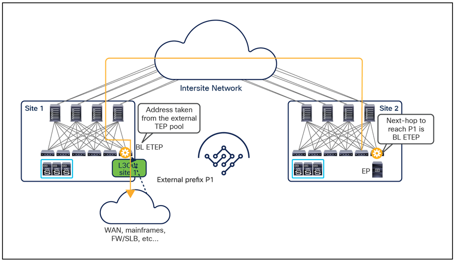
Establishment of leaf-to-leaf VXLAN tunnel across sites
Without the external TEP pool, the establishment of the VXLAN tunnel shown above would mandate that the original TEP pool assigned to each fabric was unique and routable across the ISN, which is often perceived as a too stringent requirement. Additionally, there may be scenarios where the original TEP pools of fabrics that are part of the same Multi-Site domain may be overlapping, which would prevent the establishment of the leaf-to-leaf tunnel shown above.
The configuration of the external TEP pool on NDO in conjunction with the creation of the contract between the internal EPG and the external EPG causes the establishment of MP-BGP VPNv4 (or VPNv6) adjacencies between the spines deployed in separate sites. This is the reason why the external TEP pool should be assigned to all sites part of the same Multi-Site domain, even if a local L3Out was not initially configured.
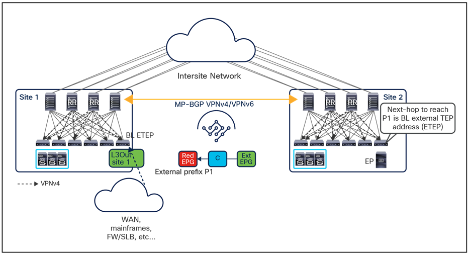
VPNv4/VPNv6 BGP Adjacencies across sites
Those adjacencies are used to exchange reachability information for all the tenant external prefixes that are learned from an L3Out connection and are established in addition to the already existing MP-BGP EVPN sessions used to exchange endpoint reachability information. In the example in Figure 110, above, the external prefix P1 received on the L3Out in site 1 is first distributed to all the local leaf nodes via the MP-BGP VPNv4 control plane leveraging the route reflector function configured on the local spines. Subsequently, it is advertised from the spines in site 1 to the spines in site 2, which then propagates the information to the local leaf nodes. The end result is that the leaf in site 2 where the Red EPG endpoint is connected adds an entry to its routing table specifying the reachability of the prefix P1 via the external TEP address of the BL node in site 1.
It is important to notice how differently from regular intersite (east-west) communication between endpoints, the spines on the receiving site 1 are not involved in any VNID/Class-ID translations for intersite communication to external prefixes (Figure 111).
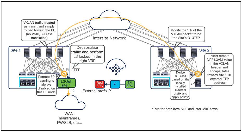
No need for VNID/S-Class translation on the receiving spines
This is because the VXLAN tunnel is established directly to the BL node and the spines in site 1 (as well as the ones in site 2) just become a routed hop in the underlay infrastructure allowing for the VXLAN communication to happen. This has two consequences:
● The information about the L3VNI value for the L3Out in site 1 must be propagated from site 1 to site 2 via the MP-BGP VPNv4 control plane. This allows the compute leaf in site 2 to add this information in the VXLAN header of the packet and ensures that when the BL node in site 1 receives the traffic, it can perform the Layer 3 lookup into the right VRF before sending the traffic out of the L3Out connection. Depending on the use case, the VRF could be the same of the endpoint in site 2 or a different VRF.
● The security policy is always applied on the compute leaf in site 2, as the class-id for the external EPG deployed in site 1 is locally programmed there.
● The Red EPG endpoint information can never be learned on the BL node in site 1 based on data-plane activity (as normally happens); this is because, as previously mentioned, no class-ID/VNI translation happens on the spines in site 1 (since the traffic is destined directly to the VTEP of the BL node), therefore the source class-id identifying the Red EPG in site 2 may have no meaning (or a complete different meaning) in the APIC domain in site 1.
The return flow from site 1 to site 2 is depicted in Figure 112, below.
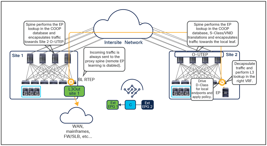
Return traffic from the L3Out to the remote endpoint
The following are some specific points to highlight:
● Traffic received from the L3Out connection and destined to the remote endpoint part of the Red EPG is always encapsulated by the BL node toward the local proxy spine service, since as previously mentioned there will never be specific endpoint information learned on the BL node. The BL node will insert in the VXLAN header the L3VNI identifying the VRF of the endpoint destination assigned in the local site.
● The local spine would then encapsulate to the spine nodes in the remote site where the destination endpoint has been discovered. This is the normal behavior for intersite communication already described in the “Cisco ACI Multi-Site overlay data plane” section and allows the receiving spines to perform the normal S-Class/VNID translation services that are normally done for east-west communication between endpoints.
● The receiving compute leaf node will then be able to perform the Layer 3 lookup in the right VRF, apply the policy and, if allowed, forward the traffic toward the destination endpoint.
Figure 113 shows, instead, the transit routing use case where traffic is routed between L3Out connections deployed across separate sites.
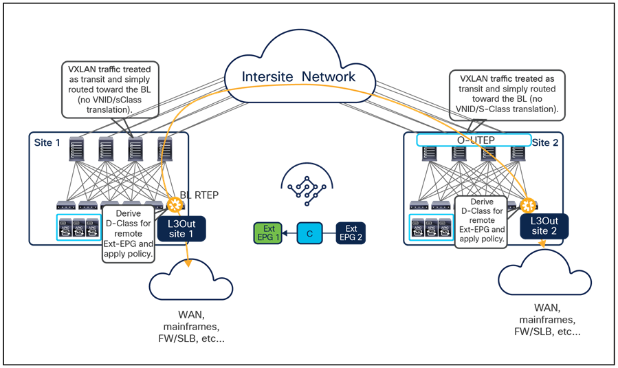
Transit routing across ACI sites
Independently from the fact that transit routing happens inside the same VRF or between separate VRFs (shared services use case), the VXLAN tunnel is always established directly between the BL nodes deployed in separate sites and the spines simply route the VXLAN encapsulated traffic.
From a policy perspective, the contract is always applied on the compute nodes, since it is always possible to locally derive the class-ID of the remote external EPG.
Intersite L3Out deployment considerations
When deploying intersite L3Out, the first decision to make is how to deploy the L3Out configuration and the associated external EPGs. Starting from Cisco Multi-Site Orchestrator Release 2.2(1), it is in fact possible to configure an L3Out object directly on an Orchestrator template (this has instead been possible for external EPGs from the very first Orchestrator release).
It is, however, important to clarify that the specific L3Out configuration (logical nodes, logical interfaces, routing protocols, route-maps, etc.) must still be performed at the APIC level. Exposing the L3Out “container” on the Orchestrator is mostly required to be able to advertise a specific BD subnet deployed in a site out of the L3Out connection deployed in another site, how it will be clarified better below.
Since both L3Outs and external EPGs can be created on NDO, the first consideration is if they should be configured as stretched objects (defined on a template mapped to multiple sites) or not.
● For what concerns the L3Out object, it is probably operationally simpler to name the L3Out in each site uniquely. This requires the creation of a separate L3Out in each template mapped to its unique site. Doing so it also allows to create the L3Out objects only in the specific site(s) that are truly connected to the external network domain.
● In brownfield scenarios, where the L3Out connections are already deployed in one or more sites, it is recommended to import the L3Out object from each APIC domain into the specific template mapped to that site.
● As previously discussed, the external EPGs can be created as stretched objects or not, mostly depending on the resources to which it provides connectivity: for the WAN, it is quite typical to have access to the same external resources from all the sites that have deployed L3Out connections, hence the use of a stretched external EPG(s) would simplify the policy definition. On the other side, if the L3Out provides access to a mainframe server connected in a specific site, a local Ext-EPG would make more sense.
● Independently from the deployment of the external EPG(s) as local or stretched object(s), it is always then required to link them to the deployed L3Out connection(s).
Once the L3Out(s) and the external EPG(s) have been created, it is then possible to establish connectivity between internal resources and the external network or enable routing between external networks through the ACI Multi-Site architecture (L3Out-to-L3Out communication or transit routing).
Before the introduction of Intersite L3Out, the traffic path between internal endpoints and the external network was pretty deterministic, as previously discussed:
● For endpoints belonging to EPGs/BDs locally defined in a site (i.e. not stretched) or stretched across sites, outbound communication was only possible via local L3Out connections.
● For endpoints belonging to EPGs/BDs locally defined in a site (i.e. not stretched), inbound communication was also only possible via the local L3Out, as it was not possible to advertise the BD subnet(s) out of a remote L3Out connection.
● For endpoints belonging to EPGs/BDs stretched across sites, it was possible for inbound flows to keep a sub-optimal path across the ISN when using the L3Out in a remote site. The option of enabling host-based routing advertisement has been made available from Cisco ACI Release 4.0(1) to ensure that inbound flows always take an optimal path.
The enablement of Intersite L3Out can change the behavior described above, so it is quite important to understand the specific functional implications of doing so.
Figure 114 shows the optimal outbound traffic path using always the local L3Out connection as the preferred option (in this example, the Red and Green EPGs/BDs are not stretched but locally defined in each site).
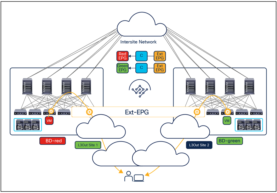
While this is the only supported behavior without configuring intersite L3Out, things may change once that functionality is enabled depending on the specific routing protocol used to connect the ACI fabrics to the external network:
● When using OSPF with the external network, if the same external prefix is received via the L3Out in site 1 and site 2, by default all the leaf nodes in each site would prefer the local outbound path. This is because the received external prefix is injected by the border leaf nodes in each site into the ACI VPNv4 control plane, and also exchanged across sites via the VPNv4 sessions established between the spines (see Figure 114, above); without applying any specific route-map on the border leaf nodes to modify the BGP attributes of such prefix, each leaf would always prefer the information received from the border leaf nodes that are topologically closer from an IS-IS metric perspective (hence the border leaf nodes in the local site).
● When using EIGRP with the external network, the EIGRP metric associated to the prefixes received on the L3Outs is propagated as MED in the ACI VPNv4 BGP process running inside the fabric. This means that if the same prefix is received on the L3Out of site 1 and site 2, the local L3Out would be used by default for outbound flows only if the EIGRP metric is the same. If the EIGRP metric of the prefix received on the L3Out of a specific site is “better” (i.e., lowest), than the prefix will be injected into BGP with a “better” (lower) MED value, so all the outbound flows (from the local and the remote sites) will be sent via that L3Out connection.
● When using BGP with the external network (usually EBGP is the common option), the BGP attributes for the prefix advertised into the ACI VPNv4 control plane will instead be carried by default from the external IPv4/IPv6 peering. This means that if, for example, the AS-Path attribute for the route received in site 1 was worse (that is, longer) than the one for the same route received in site 2, the outbound communication between all the leaf nodes part of the same Multi-Site domain would always prefer the L3Out in site 2 (Figure 115).
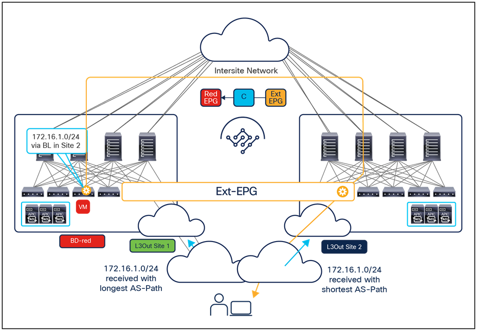
Suboptimal outbound traffic path
One important point to clarify is that in the current implementation, the enablement of Intersite L3Out implies that any prefix learned in a given site on any of the local L3Out connections would always get advertised to all the remote sites. Those prefixes will then be installed on the leaf nodes of the remote sites where the corresponding VRFs have been deployed. This may create unexpected traffic path scenarios, as in the example shown in Figure 116.
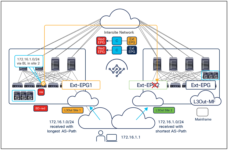
Possible dropping of outbound traffic when using separate external EPGs
In this specific case, Intersite L3Out is enabled to allow communication between endpoints of the Red EPG connected in site 1 with a mainframe server deployed behind a L3Out connection in site 2 (hence the contract configured between Red EPG and the Ext-EPG associated to the L3Out-MF). Therefore, external prefixes learned on both the L3Outs deployed in site 2 would be propagated to site 1 and in this specific example the AS-Path attribute associated to the 172.16.1.0/24 prefix would cause endpoints in site 1 to prefer the path via the L3Out in site 2. When deploying a stretched external EPG, this would cause the suboptimal outbound path previously shown in Figure 115. If, instead, separate external EPGs are deployed per site, as in the example in Figure 116, the communication between the Red EPG and the external client would be dropped, since no contract has been created between the Red EPG in site 1 and the external EPG in site 2. It is therefore important to carefully consider the possible impact on existing communication patterns before enabling Intersite L3Out.
● Independently from the routing protocol used with the external routed domain, it is still possible to force outbound flows to use a specific L3Out in a site by applying a specific inbound route-map on the BL nodes in site 2 to tune a specific BGP attribute before injecting the prefix into the VPNv4 control plane. For example, tuning local-preference is the recommended approach when the two fabrics are part of the same BGP ASN (the highest value is the best, default is 100), whereas tuning AS-Path is instead recommended If they are part of different ASNs, because the local-preference attribute is not carried across EBGP sessions. Figure 117 shows a scenario where all the outbound communications for a given VRF are enforced via the L3Out connection of site 2 by setting a longer AS-Path value (using AS-Path prepend) for all the prefixes received on the L3Out in site 1.
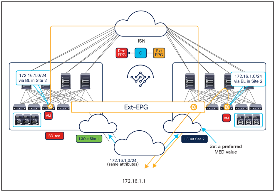
Forcing outbound traffic through a specific L3Out
Note: Setting the AS-PATH for external prefixes received on the BL nodes is only possible when running BGP as the routing protocol between the BL nodes and the external routers.
For what concerns inbound traffic flows, instead, the enablement of Intersite L3Out may cause the behavior captured in Figure 118, below.
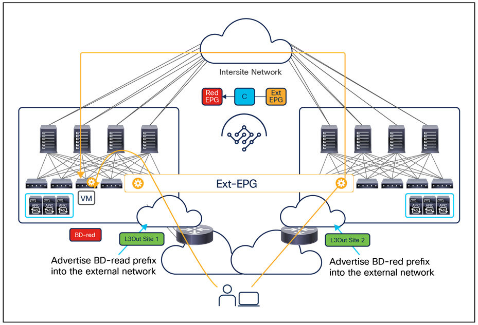
Creation of suboptimal inbound traffic path
In this example, Intersite L3Out is enabled to ensure that in case of the failure of the local L3Out in site 1, the Red endpoint could still communicate with the external network via the L3Out connection deployed in site 2. In order for this to be possible, it is obviously required that the subnet’s prefix associated to the BD-Red (locally deployed in site 1) be announced not only out of the L3Out in site 1 but also out of the L3Out in site 2.
Note: The announcement of a BD-defined in a site from the L3Out of a remote site can be controlled by mapping the BD to the L3Out object directly on the Orchestrator. This is one of the reasons why, since Cisco Multi-Site Orchestrator Release 2.2(1), we started exposing the L3Out object on the GUI. If that approach is not desirable, it is possible to use a route-map applied to the L3Out directly at the APIC level instead.
As a consequence, depending on the specific routing design in the external network, it could happen that traffic originated from an external client and destined to a Red endpoint gets steered toward the border leaf nodes in site 2, despite the fact that the BD-Red is not stretched across sites but only locally confined in site 1.
This behavior could also result surprising, especially considering the behavior in pre-4.2(1) ACI software releases where the IP prefix for a BD locally defined in a site could only be announced out of a local L3Out connection. It is therefore recommended to always consider this possible implication of enabling the Intersite L3Out functionality. As a possible solution, it is possible to apply a route-map to the L3Out directly at the APIC level, to modify the properties of the prefixes externally advertised. When peering EBGP with the external routers, for example, it could be feasible to perform an AS-Path prepend configuration to make the inbound path less preferable on the site where the BD is not originally deployed.
Different network-services-integration models can be considered when discussing a Cisco ACI Multi-Site architecture.
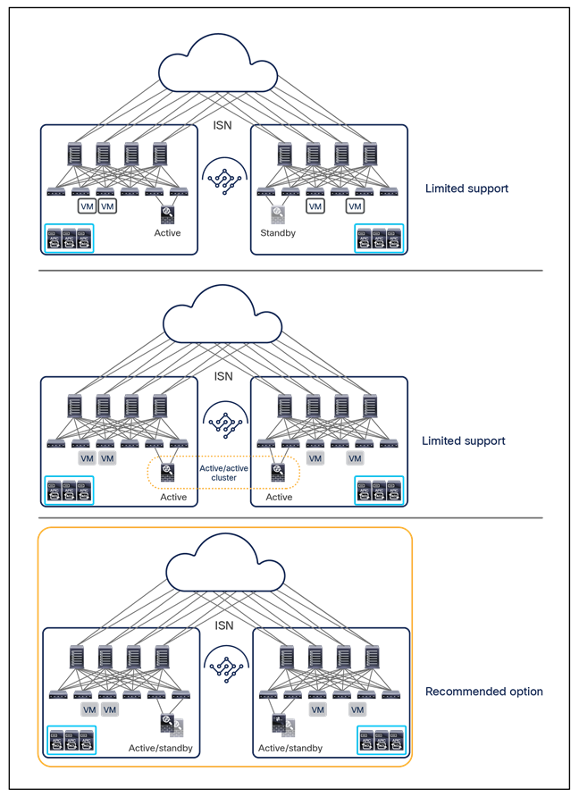
Network-services-integration models with Cisco ACI Multi-Site
The first two models call for the deployment of clustered services between sites: up to Cisco ACI Release 5.1(1), support for active/standby clusters of service nodes deployed across sites is very limited and restricted to the scenarios where Cisco ACI only performs Layer 2 forwarding (firewall as the default gateway for the endpoints or firewall in transparent mode).
Starting from Cisco ACI Release 4.2(1), the introduction of the intersite L3Out functionality allows to deploy an active/standby cluster of perimeter FW nodes connected to an L3Out connection in each site, as long as there is no requirement for L2 connectivity on the data VLANs between the service nodes deployed in separate sites (since it is not possible to extend across sites the BD associated to the L3Out).
Support for active/active clusters of service nodes deployed across sites is also limited and mostly depends on the definition of “active/active”: if all the firewall nodes that are part of the same cluster own the same MAC/IP address, which is the case, for example, when clustering Cisco FTD firewalls, the nodes can’t be deployed across separate fabrics. On the other side, if each node in the cluster were using a different MAC/IP address, it could be possible to connect them in different sites.
Note: Generally speaking, Cisco ACI Multi-Pod is the recommended architecture for the deployment of clustered services across data centers. For more information, please refer to the white paper below: https://www.cisco.com/c/en/us/solutions/collateral/data-center-virtualization/application-centric-infrastructure/white-paper-c11-739571.html
Given the fact that the Cisco ACI Multi-Site architecture has been designed to interconnect separate ACI fabrics, both at the network fault domain and management levels, it is expected that the recommended option for services integration calls for the deployment of independent clustered services (active/standby or even active/active) inside each fabric.
Detailed information about the integration of service nodes in an ACI Multi-Site architecture can be found in the white paper below: https://www.cisco.com/c/en/us/solutions/collateral/data-center-virtualization/application-centric-infrastructure/white-paper-c11-743107.html
Virtual machine manager integration models
Virtual Machine Manager (VMM) domains can be integrated into a Cisco ACI Multi-Site architecture. Separate VMM domains are created at each site because the sites have separate APIC clusters. Those VMM domains can then be exposed to the Cisco Nexus Dashboard Orchestrator in order to be associated to the EPGs defined there, as it will be clarified later in this section.
Two deployment models are possible:
● Multiple VMM instances (for example, vCenter servers, SCVMM) can be used in each site, each one paired with the local APIC cluster.
● A single VMM instance can be used to manage hypervisors deployed across sites and paired with the different local APIC clusters. This deployment model is only possible when integrating with VMware vCenter.
The next two sections provide more information about these models. For more information about how to configure VMM domains with specific supported VMMs (VMware vCenter Server, Microsoft System Center VMM [SCVMM], and OpenStack controller) refer to the following link: https://www.cisco.com/c/en/us/td/docs/switches/datacenter/aci/apic/sw/2-x/virtualization/b_ACI_Virtualization_Guide_2_3_1.html.
It is also worth noticing that VMM integration with Multi-Site is also supported when deploying Cisco AVE as virtual switch, but only from Cisco ACI Release 4.2(1).
Multiple virtual machine managers across sites
In a Multi-Site deployment, multiple VMMs commonly are deployed in separate sites to manage the local clusters of hypervisors. This scenario is shown in Figure 120.
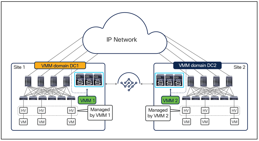
Multiple virtual machine managers across sites
The VMM at each site manages the local hosts and peers with the local APIC domain to create a local VMM domain. The model shown in Figure 120 is supported by all of the VMM options available with Cisco ACI: VMware vCenter Server, Microsoft SCVMM, and OpenStack controller.
The configuration of the VMM domains is performed at the local APIC level. The created VMM domains can then be imported into the Cisco Nexus Dashboard Orchestrator and associated with the EPG specified in the centrally created templates. If, for example, EPG 1 is created at the Multi-Site level, it can then be associated with VMM domain DC1 and with VMM domain DC2 before the policy is pushed to Sites 1 and 2 for local implementation.
The creation of separate VMM domains across sites usually restricts the mobility of virtual machines across sites to cold migration scenarios. However, in specific designs using VMware vSphere 6.0 and later, you can perform hot migration between clusters of hypervisors managed by separate vCenter Servers. Figure 121 shows the steps required to create such a configuration.
Note: At the time of this writing, vCenter Server Release 6.0 or later is the only VMM option that allows live migration across separate Cisco ACI fabrics. With other VMMs (such as vCenter releases earlier than 6.0 and SCVMM), if you want to perform live migration, you must deploy the VMMs in a single Cisco ACI fabric (single pod or Multi-Pod).
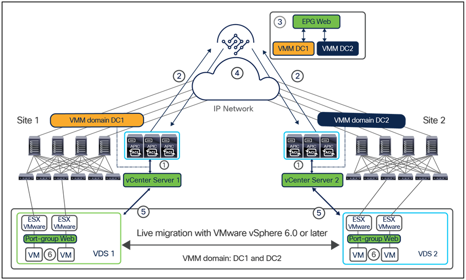
Live migration across VMM domains with VMware vCenter 6.0 or later
1. Create a VMM domain in each fabric by peering the local vCenter Server and the APIC. This peering results in the creation of a local VMware Distributed Switch (VDS 1 at site 1 and VDS 2 at site 2) in the ESXi clusters.
2. The created VMM domains can then be exposed to the Cisco Nexus Dashboard Orchestrator.
3. The user defines a new web EPG in a template associated with both sites 1 and 2. The EPG is mapped to a corresponding web bridge domain, which must be configured as stretched across sites (BUM forwarding is optional). At each site, the EPG then is associated with the previously created local VMM domain.
4. The template policy is pushed to sites 1 and 2.
5. The EPGs are created in each fabric, and because they are associated with VMM domains, each APIC communicates with the local vCenter Server that pushes an associated web port group to each VDS.
6. The server administrator can then connect the web virtual machines to the newly created web port groups. At this point, live migration can be performed across sites.
Notice that the live migration described above can only be manually triggered, as vSphere Distributed Resource Scheduler (DRS) is not supported across VDS and hence it is not possible to leverage that dynamic trigger. Also, functionalities as vSphere High Availability (HA) or Fault Tolerance (FT) are also supported only intra-VDS and hence cannot be leveraged across fabrics.
Single virtual machine manager across sites
Figure 122 shows the scenario in which a single VMM is used across sites.
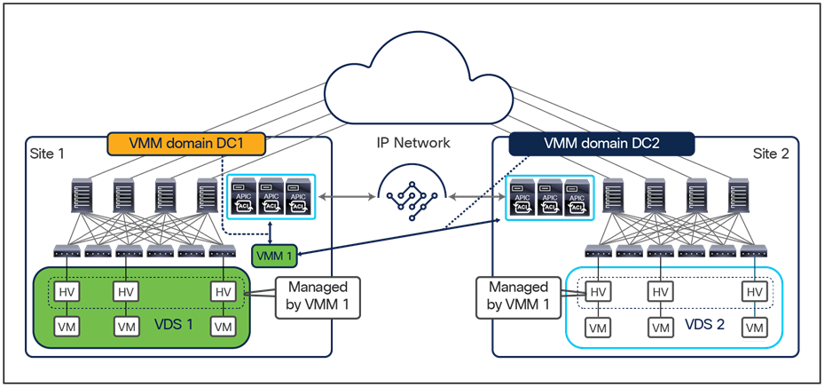
Single VMM with separate VMM domains across sites
In this scenario, supported only when integrating the APICs with a VMware vCenter server, a VMM is deployed in site 1 but manages a cluster of hypervisors deployed within the same fabric and also in separate fabrics. Note that this configuration still leads to the creation of different VMM domains in each fabric with the consequent pushing of different VDS switches to the ESXi hosts locally deployed. This scenario essentially raises the same considerations discussed in the previous section about the support for cold and hot migration of virtual machines across fabrics.
Brownfield integration scenarios
Nexus Dashboard Orchestrator often needs to be introduced to manage ACI fabrics already deployed in production. This means that configurations for those fabrics have already been provisioned leveraging the APICs, so the main question is how to add them to the Multi-Site domain and how to ensure that, once that is done, the configurations can be continued to be managed from NDO.
Two typical scenarios seen in real-life deployments where there may be a need to introduce NDO to manage already existing ACI fabrics are shown in Figure 123.
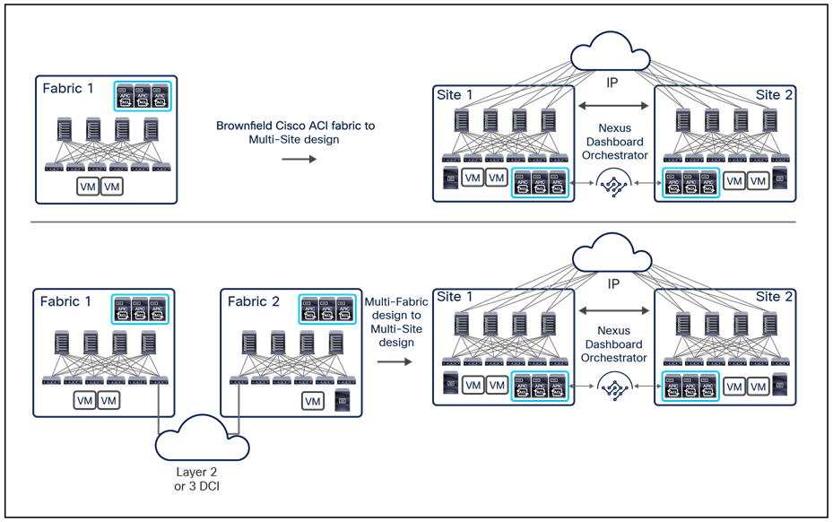
Cisco ACI Multi-Site migration scenarios
The use case at the top of Figure 123 is quite straightforward. It consists of adding one (or more) Cisco ACI fabrics to an existing one. As already discussed in the “Integration of Cisco ACI Multi-Pod and Multi-Site” section, this use case may be relevant for customers who are running an active/active design across a couple of DC locations (using a single Multi-Pod fabric deployment) and who need to connect this environment to a new DR site.
The use case at the bottom of Figure 123 involves converting an existing Multi-Fabric design to a Cisco ACI Multi-Site design. As discussed in the “Layer-3-only connectivity across sites” section, while it is possible to continue to run the ACI fabrics as “autonomous” and establish Layer 3 connectivity only between them through the L3Out data path, there are several advantages when introducing NDO as a single point of management and using the VXLAN data path for east-west connectivity across sites. Additionally, there are several deployments put in production in the past that leveraged an external DCI technology (OTV, VPLS, etc.) for extending Layer 2 connectivity between independent ACI fabrics. This “dual fabric” design is not recommended anymore, so a migration path needs to be provided toward Multi-Site.
From an infrastructure perspective, the biggest change in both scenarios above consists in providing connectivity between the spines of different fabrics across the Inter-Site Network (ISN). From a provisioning point of view, the major shift is starting to handle the configuration of the policies from NDO instead of from APIC. This has obvious implications in terms of automation, because there are different APIs to interact with NDO compared to the APIs used with APIC. Also, and more importantly, it raises the question how to efficiently import into NDO existing policies originally defined on APIC.
Importing existing policies from Cisco APIC into Cisco Nexus Dashboard Orchestrator
The two typical scenarios for importing existing policies from Cisco APIC into NDO are highlighted in Figure 124.
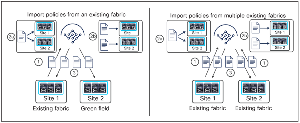
Importing policies into Cisco Nexus Dashboard Orchestrator
Note: The considerations below specifically apply to the import of tenant policies. As previously described in the “New template types introduced in NDO Release 4.0(1)” section, starting from Release 4.0(2) the NDO can also manage and provision fabric and monitoring policies, so the same considerations can be extended to those template types.
Before being able to import the tenant policies, it is obviously required to ensure that the tenant exists in NDO. This can be done by directly creating in NDO a tenant with exactly the same name as the tenant already deployed in site 1 or by “importing” that tenant from site 1. Note that performing a tenant “import” at this point only creates the tenant in NDO without importing any tenant-related configuration.
The scenario on the left of Figure 124 is quite straightforward, and the following are the required import steps:
1. Existing policies for a given tenant must first be imported from the already deployed Cisco ACI fabric into NDO.
2. The imported policies should be organized in different templates, as previously discussed in the “Deploying NDO schemas and templates” section. For example, a tenant configuration that should remain locally provisioned only in the existing fabric should be imported into a template that is only associated to that site. If the plan is to extend connectivity across sites for a specific VRF, the VRF should be imported into a template that is associated to both sites. The same holds true for other objects such as BDs, EPGs, or contracts that are already deployed in site 1 but that should be stretched also to site 2. Additionally, new local policies can be created for site 2 in a dedicated template associated with that site.
It is worth noticing that, when importing a BD into a stretched template, it may be required to change the configuration of the BD to enable the “L2 Stretch” option. When doing so, the warning message shown below is displayed:
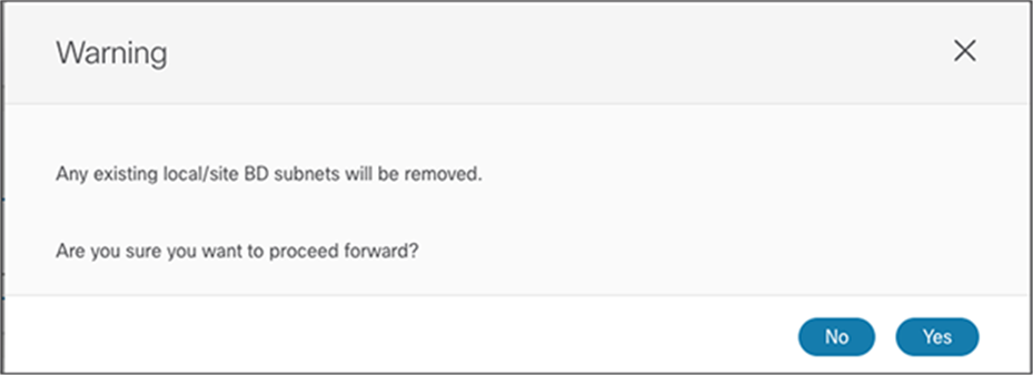
Warning message when enabling the “L2 Stretch” option for a BD
This is simply highlighting the fact that, when a BD gets L2-stretched across sites, the BD subnet becomes a global property common to all the sites (this is an instance of distributed anycast gateway functionality), so it must be configured as part of the global template configuration and not as a site-local property. However, doing that and deploying the template does not cause any connectivity issues in the original site (where the BD subnet was already deployed) and just causes the enablement of the default gateway functionality in site 2.
Note: If BD/EPG pairs are initially imported in a template associated only to the original site 1 (since they are local-only objects), Cisco Nexus Dashboard Orchestrator offers the possibility of migrating those BD/EPG pairs to a stretched template at a later time, in case the requirement arises to stretch those objects. The opposite operation is also possible, when BD/EPG pairs that are stretched must be removed from a remote site and become instead site-local objects. As of NDO Release 4.0(2), this capability of migrating objects across templates is restricted to BDs and EPGs, and only if the templates are associated to the same tenant
The configuration is then pushed back from NDO toward the APIC domains. This ensures that the objects already existing on site 1 will simply get an added annotation attribute to graphically display the information that they are now managed by NDO. At the same time, new objects will be created on site 2.
Note: Re-pushing imported policies to site 1 is not disruptive for existing communication already established inside the fabric and between the fabric and the external network domain.
Similar considerations apply for the use case on the right in Figure 124, with an additional and important consideration: one of the cardinal rules to follow in Multi-Site deployment is that if a given object must exist in different sites and represents the same “thing” (such as, for example, a stretched EPG or BD), it needs to be seen and managed from NDO as a single object. This means that if there is a requirement to import existing policies into NDO from different APIC domains, the names for those policies already defined across sites for a given tenant (including the tenant name itself) must have been assigned consistently. This is because NDO does not currently offer the capability of “merging” objects that are named differently.
For example, imagine a scenario where OTV is deployed between two ACI fabrics to extend a specific EPG/BD across sites. If the EPG and BD in each site are named consistently, those objects can simply be imported from both APIC domains into a stretched template (in order also to import their site-specific properties). But if those objects were originally named EPG-Site1/BD-Site1 and EPG-Site2/BD-Site2, once imported into NDO they would be considered to be different objects.
After considering the important point just discussed, the brownfield import procedure for the scenario on the right of Figure 124 simply becomes the following:
1. Existing policies for a given tenant must first be imported from both of the already deployed Cisco ACI fabrics into NDO.
2. The imported policies should be organized in different templates, as already discussed for the previous scenario, and keeping in mind the naming considerations for common objects that must be added to stretched templates.
3. The configuration is then pushed back from NDO toward the APIC domains, annotations are added to all of the objects, and, from this moment on, NDO is in charge of fully managing the tenant provisioning.
This section provides a summary of best practices and hints to help you easily and smoothly deploy a Cisco ACI Multi-Site design. These recommendations are based on our own learning and experience in deploying real Cisco ACI Multi-Site designs in customer networks from the proof-of-concept phase through deployment in the production environment.
Cisco Nexus Dashboard Orchestrator cluster deployment
Note the following recommendations for deploying a Cisco Nexus Dashboard Orchestrator cluster:
● When running MSO Release 3.1(1) or earlier, connect the Cisco Multi-Site Orchestrator cluster to the APICs using the out-of-band (OOB) management network, because this is the only officially supported option. With NDO running on Nexus Dashboard, you have instead the flexibility of communicating with the APICs using their out-of-band (OOB) address, in-band (IB) address, or both.
● The Cisco cluster nodes used to run the Orchestrator services should not be deployed within a Cisco ACI fabric that it is managing as a site (to avoid being able to make changes to the configuration when intra-fabric connectivity is impacted). It should preferably be deployed outside the Cisco ACI fabric, connected to an infrastructure that provides access to the APIC’s OOB/IB (or both) interfaces, depending on the specific Orchestrator release used.
● Each Cisco Multi-Site Orchestrator cluster node (or Nexus Dashboard node if running the Orchestrator as a service on ND) should have a routable IP address, and all three nodes must be able to ping each other. The nodes of the Multi-Site Orchestrator (or Nexus Dashboard) cluster can use IP addresses assigned from separate IP subnets (that is, there is no L2 adjacency requirement between them).
● When deploying the Docker-based version of Multi-Site Orchestrator, ensure that every MSO node is deployed on a separate ESXi host to increase the high availability of the cluster.
● When deploying NDO as a service on Nexus Dashboard, the recommendation is to dedicate a virtual ND cluster to the Orchestrator service (i.e., do not host other applications on this cluster).
● The maximum RTT latency between the MSO nodes in a cluster should be less than 150 msec. For NDO nodes (or ND nodes) in a cluster should instead be less than 50 ms.
● The maximum RTT latency between a Cisco Multi-Site Orchestrator cluster node and a Cisco ACI APIC node can be up to 1 second when running the Docker-based MSO cluster. The maximum RTT latency is reduced to 500 msec when running the Orchestrator service on a Nexus Dashboard compute cluster.
● A Cisco Multi-Site Orchestrator cluster uses the following ports for the internal control plane and data plane, so the underlay network should always ensure that these ports are open (in the case of an ACL configuration of a firewall deployment in the network):
◦ TCP port 2377 for cluster management communication
◦ TCP and UDP port 7946 for communication among nodes
◦ UDP port 4789 for overlay network traffic
◦ TCP port 443 for Cisco Multi-Site Orchestrator User Interface (UI)
◦ IP 50 Encapsulating Security Protocol (ESP) for encryption
● IPsec is used to encrypt all intra–Multi-Site Orchestrator cluster control-plane and data-plane traffic to provide security because the MSO nodes can be placed up to 150 ms RTT apart and intra-cluster communication could consequently traverse a not-secure network infrastructure.
● For Docker-based installations, the minimum specifications for Cisco Multi-Site Orchestrator virtual machines vary with the specific software release deployed, as shown again below:
◦ For Cisco Multi-Site Orchestrator Release 1.0(x):
VMware ESXi 5.5 or later
Minimum of four virtual CPUs (vCPUs), 8 Gbps of memory, and 50 GB of disk space
◦ For Cisco Multi-Site Orchestrator Release 1.1(x):
VMware ESXi 6.0 or later
Minimum of four virtual CPUs (vCPUs), 8 Gbps of memory, and 50 GB of disk space
◦ For Cisco Multi-Site Orchestrator Release 1.2(x) and above:
VMware ESXi 6.0 or later
Minimum of eight virtual CPUs (vCPUs), 24 Gbps of memory, and 100 GB of disk space
◦ For Cisco Multi-Site Orchestrator Release 2.2(x) and above
VMware ESXi 6.0 or later
Minimum of eight virtual CPUs (vCPUs), 48 Gbps of memory, and 64 GB of disk space
● For deployments where NDO is deployed as an application on top of a Cisco Service Engine or Cisco Nexus Dashboard compute cluster, please refer to the Service Engine and Nexus Dashboard documentation for specifics physical servers’ and/or virtual machines’ requirements.
Day-0 Multi-Site infrastructure configuration
Here are the recommended best practices for deploying Multi-Site connectivity across separate fabrics:
● All the physical interfaces connecting the spine nodes to the intersite network must be on Cisco Nexus EX platform line cards (or a newer generation). Generation-1 spine nodes are not supported and can be used only for intra-fabric communication.
● Generally speaking, the APIC fabric ID in a Multi-Site deployment can be unique for each fabric part of the Multi-Site domain, or the same value can be used across sites (this could be useful/needed when adding to the same Multi-Site domain brownfield fabrics with overlapping fabric IDs). There are, however, a couple of specific scenarios to consider that may influence the choice of how to define those fabric IDs:
a. The deployment of shared GOLF (supported from Cisco ACI Release 3.1(1)), specifically when auto-RT is enabled, and all the sites are part of the same BGP ASN. In this case it is mandatory to deploy separate fabric IDs across sites part of the same Multi-Site domain. If any of the two conditions previously mentioned is not true (i.e. auto-RT is disabled or the fabrics are part of different BGP ASN), it is instead perfectly fine to deploy the same fabric ID across all the sites even in a shared GOLF design.
b. The issue captured in CSCvd59276 that may happen if the fabrics part of the Multi-Site domain use different fabric IDs and there is the need to configure an IGMP Snooping Querier on an ACI BD. As mentioned in the description of the DDTS above, using the same fabric ID would solve the problem. Alternatively, it is still possible to keep the fabric IDs different, as long as higher querier IP address is configured for one of the fabric of the Multi-Site domain.
Note: The configuration of an IGMP Snooping Querier is only required for supporting L2 multicast traffic flows between endpoints when PIM is not enabled on the bridge domain. Enabling PIM on the bridge domain automatically turns on the IGMP Snooping Querier function on the SVI so no explicit querier configuration is required. Also, IGMP Snooping Querier configuration is not needed if there is a querier already deployed in the external network infrastructure.
● The Cisco ACI Multi-Site site ID or site name must be unique across all sites. This parameter is configured directly on the Cisco Nexus Dashboard Orchestrator and cannot be changed after it has been assigned. To reconfigure the site ID, you will need to perform a clean wipe to return to the factory defaults.
Note: The Cisco ACI Multi-Site ID is different from the Cisco ACI fabric ID assigned on the APIC.
● While intersite connectivity can be established between ACI fabrics that have deployed overlapping TEP pools, the best practice recommendation for greenfield deployment is to assign independent TEP pools to each fabric part of the same Multi-Site domain. In any case, it is highly recommended to configure the first layer of ISN routers connected to the spines in each site to filter out the TEP-pool advertisement to the ISN.
● The external TEP pools that can be assigned on Cisco Nexus Dashboard Orchestrator to enable intersite L3Out functionality, should have a mask ranging from /22 to /29. It is possible to define multiple external TEP pools (if needed) without any adjacency requirements between them.
Note that if an external TEP pool was already assigned from APIC to a given ACI fabric (for example, because of the deployment of remote Leaf), such a pool would be automatically imported into NDO when the ACI fabric is added to that Multi-Site domain.
● All Multi-Site control-plane and data-plane TEP addresses should be externally routable over ISN.
● Four types of TEP addresses need to be configured:
◦ Multi-Pod data-plane TEP: Configure this address directly on each APIC cluster in Cisco ACI Release 3.0(1). This configuration is mandatory even if Multi-Pod fabrics are not initially supported in a Cisco ACI Multi-Site architecture for all ACI software releases antecedent to Release 3.2(1). This configuration is not required anymore from Cisco ACI Release 3.2(1) when connecting single pod fabrics to a Multi-Site domain.
◦ Overlay Multicast TEP (O-MTEP): This address is used as the destination IP address for BUM traffic sent across the fabric in ingress replication mode.
◦ Overlay Unicast TEP (O-UTEP): This address is used as the anycast VTEP address for each pod. Configure one address per pod for a Multi-Pod fabric. This address is used as the next-hop on the local spine node to reach remote endpoints.
◦ MP-BGP EVPN Router-ID (EVPN-RID): This address is used to form MP-BGP intersite sessions. Define one unique IP address per spine node.
● When deploying Multi-Pod and Multi-Site together, the same EVPN-RID address can be used to establish EVPN adjacencies between spines of different pods (part of the same fabrics) and spines of different sites (part of different fabrics). The O-UTEP, O-MTEP, and Multi-Pod data-plane TEP addresses should always be unique.
● It is a best-practice recommendation to assign these IP addresses from a dedicated IP range and to allow the advertisement of all those specific /32 prefixes across sites. If desired, it is also possible to summarize all the /32 prefixes used in a site and send only the summary route to the remote fabrics that are part of the Multi-Site domain. When doing that, an additional configuration step is required on all the remote APIC domains to ensure that the received summary routes can be redistributed to the IS-IS control plane internal to the fabric.
● Allocate at least two spine nodes for Multi-Site BGP-EVPN peering in a Cisco ACI pod (for redundancy). Note that not all the spine nodes need to be BGP-EVPN peers.
● When a site is deployed as a Multi-Pod fabric, define two spines (in different pods) as BGP speakers (that is, enable BGP from NDO for those spines) and leave the remaining spines as BGP forwarders. Only the BGP speakers establish BGP EVPN adjacencies with the speakers in remote sites.
● We recommend use of full-mesh BGP-EVPN peering instead of route reflectors since it represents a simpler approach. BGP-EVPN will automatically form full-mesh iBGP and eBGP peerings.
● When route reflectors are used, they will apply to iBGP sessions only within the same Autonomous System and eBGP will still use full mesh between different Autonomous Systems. A spine node can support both types of peering at the same time.
● When deploying a Route Reflector (RR) with high availability for N sites, you can deploy 1 RR instance on a spine node in a site and deploy this across 3 sites which would cover high availability requirement for N sites instead of deploying 1 RR instance in every site.
● Use BGP and OSPF default general settings for Multi-Site ISN.
● Make sure that the source interface for the intersite BGP-EVPN sessions is configured with the MP-BGP EVPN Router-ID (with the infra L3Out connection assigned to the right loopback connector).
● Verify that the secure BGP passwords match in the various sites (if configured).
● The BGP community sample format is extended:as2-nn4:4:15.
General best practices for Cisco ACI Multi-Site design
Note the following lessons learned from trials and actual deployments of Cisco ACI Multi-Site designs:
● If WAN connectivity is over GOLF, you need to consider two scenarios:
◦ Scenario 1: Site 1 has its own non-stretched BD1 and subnet 1 and GOLF L3Out-1 connection, and site 2 has its own nonstretched BD2 and subnet 2 and GOLF L3Out-2 connection. Each GOLF L3Out connection advertises its own bridge domain subnet to its own GOLF router, so host routing is not required.
◦ Scenario 2
◦ BD1 and subnet 1 are stretched to sites 1 and 2.
◦ The Layer 2 stretch flag is enabled for BD1.
◦ Intersite BUM traffic forwarding can be enabled or disabled.
◦ Each site also has its own local GOLF L3Out connection, which advertises the subnet through its GOLF L3Out connection to its GOLF router.
◦ The subnet in the WAN will have an equal-cost multipath (ECMP) path to the two GOLF routers.
◦ Suboptimal routing of GOLF traffic over IPN is not supported. This means that traffic cannot be delivered from the GOLF router to a specific site and then be redirected to a separate site to reach a remote destination endpoint. It is therefore mandatory to enable host-route advertisement for all the stretched bridge domain.
● Intersite VXLAN tunnels must transit through the ISN and cannot use another site for transit. As a consequence, you must build enough redundancy into the ISN to help ensure that two given sites are always connected through the ISN in any node or link failure scenario.
◦ Before Cisco ACI Release 4.2(1), each site must deploy a local L3Out connection.
◦ A site cannot provide L3Out routing services for endpoints deployed in a different site.
◦ A pair of WAN edge routers can be shared across sites (traditional L3Out connection on border leaf nodes).
◦ Shared WAN edge routers across sites are supported from Cisco ACI Multi-Site Release 3.1(1) when GOLF L3Out connections are deployed
● From Cisco ACI Release 4.2(1), the Intersite L3Out functionality allows a given site to provide L3Out services to endpoints located in separate sites.
◦ Be sure that you fully understand the possible impact on existing inbound and outbound traffic flows caused by the enablement of Intersite L3Out
● Each tenant or VRF instance can have its own L3Out connection. Shared L3Out connections, where one L3Out connection is shared across multiple VRF instances, are supported with Multi-Site only from Cisco ACI Release 4.0(1).
● A Multi-Pod fabric is supported as a site in a Cisco ACI Multi-Site architecture from Cisco ACI Release 3.2(1).
● Domain (VMM and physical) definition and association are performed at the site level.
● Policies pushed to a site from Cisco Nexus Dashboard Orchestrator can be modified locally in the APIC. A warning will appear in the Nexus Dashboard Orchestrator if the policy implemented for a site is different from the policy specified in the Nexus Dashboard Orchestrator template.
● Quality-of-Service (QoS) marking in the WAN is not supported when intra-EPG isolation or microsegmentation is configured.
● Without any QoS policies configured at a site, the default DSCP value of the outer IP address of the VXLAN packet in the ISN is set to 0 (zero). You should configure a QoS DSCP marking policy on the spine node to help ensure proper QoS treatment in the ISN.
● A Multi-Site deployment can be enabled only when at least one spine interface is connected to the ISN.
● If a spine port is connected to the ISN and peering is disabled, only the data plane is enabled on that spine node.
● If a spine port is connected to the ISN and peering is enabled (i.e., the spine is configured as a BGP speaker), control-plane MP-BGP EVPN sessions are formed across spine nodes and across sites that have peering enabled through MP-BGP EVPN Router-IDs.
● MP-BGP EVPN convergence for route-reflector or full-mesh scenarios with iBGP, eBGP, or a hybrid (iBGP plus eBGP) is typically <= 1 second in lab environments for medium-size deployments. However, <= 5 seconds for convergence in real medium-size deployments is common due to external factors such as the WAN.
● Cisco Nexus Dashboard Orchestrator discovers pods and supported spine line-card information from the APIC and updates the infra configuration.
● All available infra configurations are retrieved from the APIC of the site being created from the managed objects, and the Cisco Nexus Dashboard Orchestrator configuration is auto-populated.
● The Multi-Site infra L3Out connection under the infra tenant is named “intersite” in the APIC, as shown in Figure 126.
Creation of Intersite L3Out in Cisco APIC
● When a site is added to a Multi-Site domain, the BGP RID is modified on the spines that are configured as BGP speakers. This may cause the re-establishment of intra-fabric VPNv4 adjacencies between the spines (configured as RR for the fabric) and the leaf nodes, with consequent impact on north-south communications. Therefore, it is recommended to perform the addition of the site to the Multi-Site domain during a maintenance window.
● When a site is deleted from a Cisco ACI Multi-Site deployment, its control plane and data plane functionalities will be disabled. However, Cisco Nexus Dashboard Orchestrator will retain the infra configuration and will auto-populate it if that site is added again. If desired, the infra configuration must be deleted directly from the APIC controller.
The new Cisco ACI Multi-Site architecture allows you to interconnect separate Cisco ACI fabrics, each managed by its own APIC cluster, which can be equiparated to different AWS Regions.
The use of the MP-BGP EVPN overlay control plane and VXLAN data plane encapsulation allows you to simplify the establishment of multitenant Layer 2 and Layer 3 communication across fabrics, requiring only underlay routing services from the network infrastructure that interconnects them. The use of the intersite VXLAN data plane that also carries network and policy information (metadata) allows end-to-end policy domain extension.
The introduction of Cisco Nexus Dashboard Orchestrator provides single-pane management, allowing you to monitor the health of the interconnected fabrics, perform the day-0 configuration tasks required to establish MP-BGP EVPN control-plane adjacencies, and define intersite policy templates to be implemented in the various APIC domains.
The Cisco ACI Multi-Site design complements, and does not replace, the existing Cisco ACI Multi-Pod architecture. Different use cases and business requirements call for the deployment of both options, which are characterized by some fundamental differences, as shown in Figure 127.
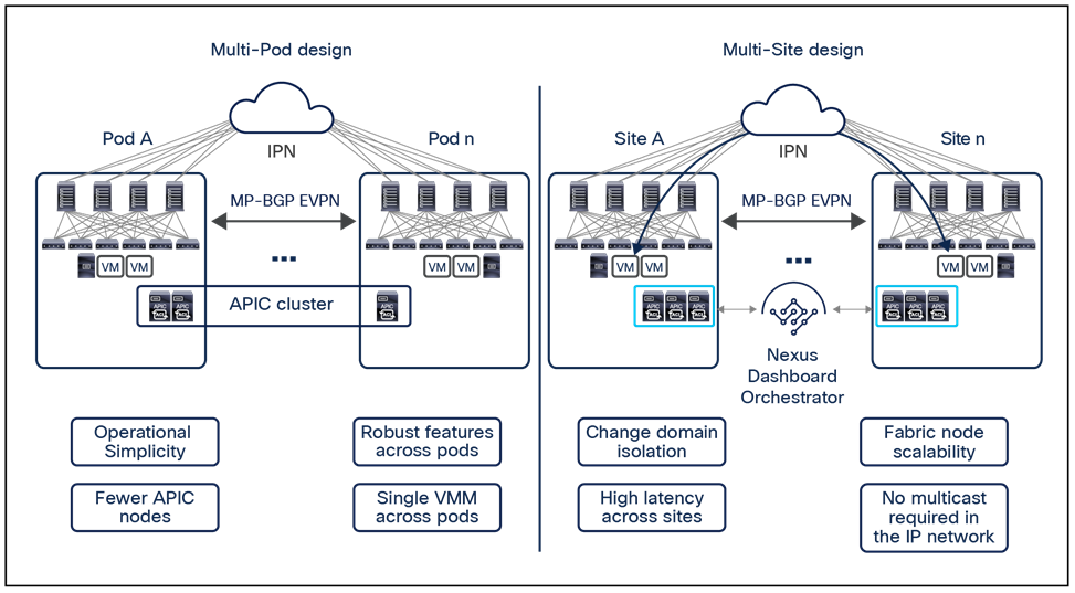
Summary of differences between Cisco ACI Multi-Pod and Cisco ACI Multi-Site architectures
The Multi-Pod design provides more operational simplicity, because a single APIC cluster manages all the interconnected pods. This design also ensures that all the Cisco ACI functions supported in a single-pod fabric are also available in a Multi-Pod fabric (service graph definition, shared L3Out connections, creation of a single VMM domain extending across pods, etc.).
The Cisco ACI Multi-Site architecture provides complete fault and change domain separation between the interconnected fabrics. It also allows you to increase the overall scale of the architecture in terms of the number of Cisco ACI nodes and endpoints that can be connected across separate sites. Finally, the Cisco ACI Multi-Site design also eliminates the need to deploy multicast in the Layer 3 infrastructure that interconnects the fabrics, because head-end replication is performed on the spine switches to allow BUM traffic to be sent across fabrics for all stretched bridge domains that require it.
From Cisco ACI Release 3.2(1), it is possible to deploy one or more Cisco ACI Multi-Pod fabrics as “sites” of a Multi-Site architecture. The combination of those two architectural options provides flexibility and feature-richness to meet the requirements for interconnecting data center networks.
For more information about the Cisco ACI Multi-Site architecture and the other architectures discussed in this paper, please refer to the documentation available at the following links:
● ACI Multi-Pod White Paper
https://www.cisco.com/c/en/us/solutions/collateral/data-center-virtualization/application-centric-infrastructure/white-paper-c11-737855.html
● ACI Multi-Pod Configuration White Paper
https://www.cisco.com/c/en/us/solutions/collateral/data-center-virtualization/application-centric-infrastructure/white-paper-c11-739714.html
● ACI Multi-Pod and Service Node Integration White Paper
https://www.cisco.com/c/en/us/solutions/collateral/data-center-virtualization/application-centric-infrastructure/white-paper-c11-739571.html
● Cisco Multi-Site Deployment Guide for ACI Fabrics
https://www.cisco.com/c/en/us/td/docs/dcn/whitepapers/cisco-multi-site-deployment-guide-for-aci-fabrics.html
● ACI Multi-Site and Service Node Integration White Paper
https://www.cisco.com/c/en/us/solutions/collateral/data-center-virtualization/application-centric-infrastructure/white-paper-c11-743107.html
● ACI Multi-Site Training Videos
https://www.cisco.com/c/en/us/solutions/data-center/learning.html#~nexus-dashboard
● ACI Remote Leaf Architecture White Paper
https://www.cisco.com/c/en/us/solutions/collateral/data-center-virtualization/application-centric-infrastructure/white-paper-c11-740861.html
Appendix A: Multi-Site Layer 3 multicast with external RP
A set of functionalities (IGMP snooping, COOP, PIM) work together within Cisco ACI for the creation of proper (*,G) and (S,G) state in the ACI leaf nodes. Figure 128 shows those functionalities in action in a PIM- ASM scenario requiring the use of an external RP.
Note: Anycast RP nodes can be deployed in the external network for providing a redundant RP functionality. In that case, MSDP or PIM can be used between the different RPs in order to synchronize source information.
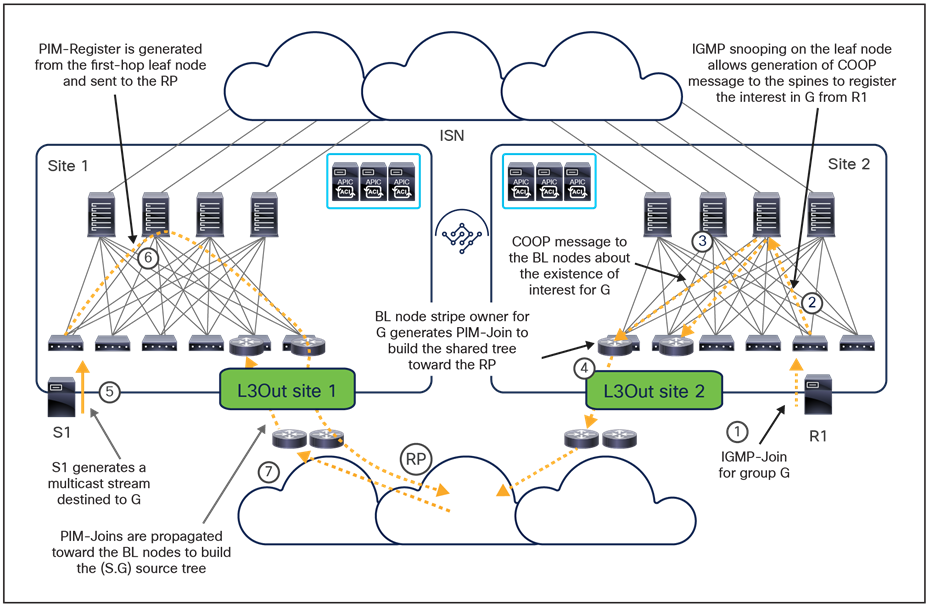
Control-plane interactions for a PIM-ASM use case
When a receiver is connected to the Cisco ACI fabric:
1. The receiver originates an IGMP-Join for declaring its interest in receiving multicast traffic for a specific group G.
2. The IGMP-Join is received by the Cisco ACI leaf node where the receiver is connected. The leaf registers the interest of a locally connected receiver (creating a (*,G) local entry) and generates a COOP message to the spines to provide the same information.
3. The spines register the interest of the receiver for the group G and generate a COOP notification to the local border leaf nodes to communicate this information.
4. One of the border leaf nodes is elected as the “stripe owner” for the multicast group G, so it generates a PIM-Join to the external routers on the path toward the RP. External PIM routers do the same to build a shared tree up to the RP.
5. At this point, a multicast source S1 is connected and starts streaming traffic destined to the group G.
6. The first-hop leaf node where the source is connected will create the (S1,G) local state and send a PIM-Register message toward the RP. PIM-Register packets are unicast packets with PIM protocol number 103 set in the IP header that will be forwarded through the Cisco ACI fabric toward the local border leaf nodes. In the current implementation, a default rule is configured on the Cisco ACI nodes to permit PIM packets, so no contract is required for this control-plane exchange to succeed.
7. The RP will then start sending PIM-Join messages toward the border leaf nodes in site 1 to build the (S1,G) source tree. This is assuming that the BD for S1 is not stretched. If the BD for S1 is stretched the join can go to either site 1 or site 2.
It is important to clarify how the use of the external RP does not mean that Layer 3 multicast forwarding between sources and receivers connected to the different sites must flow though the RP itself, since the VXLAN data-plane across the ISN is going to be used to handle this east-west Layer 3 multicast communication. However, the existence of an active L3Out connection is mandatory to allow for the control plane exchange described above.
Figure 129 shows the complete data-plane forwarding behavior under the assumption that the multicast source is connected to site 1 and receivers are connected to the local site, the remote site, and in the external network.
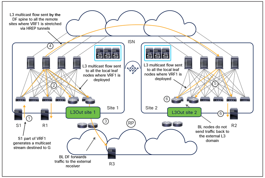
Layer 3 multicast forwarding between internal source and internal/external receivers
1. A multicast source that is part of VRF1 is connected to the leaf node and generates a multicast stream destined to the specific group G.
2. The multicast stream is received by the leaf node where the source is connected. The leaf encapsulates the traffic and sends it to the GIPo associated to VRF1. The multicast traffic is then forwarded inside the site and reaches all the leaf nodes where VRF1 has been deployed, including the border leaf nodes. It is worth noticing that in the ASM case this behavior happens only if there is a valid RP for the group deployed in the external network: the leaf would first send the register toward the RP and then forward the multicast traffic on the VRF GIPo. If there is not RP available, the FHR leaf would not be capable of forwarding multicast traffic.
3. The border leaf node that received the PIM-Join from the external router forwards the multicast stream toward the external network. At this point, the traffic will reach the external multicast receiver H3, either following a direct path or via the RP, depending on whether the Shortest-Path Tree (SPT) switchover has happened or not.
4. At the same time, the spine elected as the Designated Forwarder (DF) for VRF1 in site 1 forwards the VXLAN-encapsulated multicast stream toward all the remote sites where VRF1 has been stretched. This forwarding is performed leveraging the ingress-replication function (HREP tunnels). The VXLAN destination address used for this traffic is the Overlay Multicast TEP address associated to each site and already used also for the L2 BUM traffic forwarding across sites.
5. One of the spines inside each of the remote sites receives the multicast traffic and forwards it inside the local site along the tree associated with the VRF1 GIPo. Notice that the specific GIPo address associated to VRF1 is likely different from the one used in site 1, as it is assigned by a different APIC controller. This does not really matter, as the use of the GIPo is limited to the local fabric where it is defined.
6. The stream is received by all the leaf nodes where VRF1 is deployed, including the border leaf nodes. The reception of the multicast stream gives indications to the border leaf nodes that the stream has been delivered via the Multi-Site data-path, so the border leaf that is the designated forwarder for the group G prunes the shared tree built toward the external RP based on control-plane activity (as shown in Figure 129), to avoid sending duplicate traffic to the external receivers.
Figure 130 shows, in contrast, a scenario where the multicast source is connected to the external Layer 3 network, and the receivers are deployed inside the Cisco ACI fabrics.
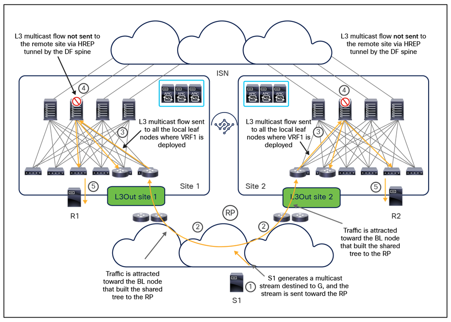
Layer 3 multicast forwarding between external source and internal/external receivers
In this case, the border leaf nodes in all the fabrics where the receivers have been connected attract the multicast stream, then forward it inside the local Cisco ACI fabric, so that the receivers can get it. At the same time, the DF spine getting the stream does not replicate it toward the remote sites, to avoid duplicate traffic reception for the remote receivers.
Note: The same data-path behavior shown in figures above applies when deploying PIM SSM. The only difference is that in the SSM case there is no need to define the external RP. The receivers, in fact, use IGMPv3 in the SSM scenario to declare their interest in receiving the multicast stream from a specific multicast source, and this leads to the creation of a multicast tree directly between the receiver and the source.
Appendix B: Previous deployment options for multi-DC orchestration services
As previously mentioned in this paper, the current recommended deployment model for Orchestration services is by running them on top of a Nexus Dashboard compute cluster (and hence becoming Nexus Dashboard Orchestrator – NDO). The following sections cover the previously available deployment models for Cisco Multi-Site Orchestrator (MSO), which should slowly disappear from customers’ production deployments.
Deploy a VM-based MSO cluster directly in VMware ESXi virtual machines
This is the deployment model supported from the very first release of Cisco Multi-Site Orchestrator (Figure 131). However, 3.1(1) is the last supported MSO release with this specific deployment option.
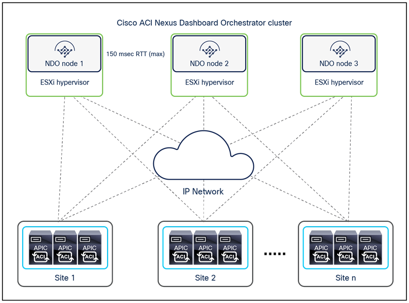
VM-based MSO cluster running on VMware ESXi hosts
With this deployment option, each Cisco Multi-Site Orchestrator node is packaged in a VMware vSphere virtual appliance. For high availability, you should deploy each Cisco Multi-Site Orchestrator virtual machine on its own VMware ESXi host so that all three virtual machines form a cluster over three different ESXi hosts to eliminate any single point of failure.
In the configuration with three virtual machines supported for the creation of the Multi-Site Orchestrator cluster, it is possible to lose one virtual machine and have the cluster still be fully functional. The cluster would instead become inactive if losing two virtual machines, which leads to the recommendation of deploying each virtual machine on a separate ESXi host.
The supported round-trip time (RTT) latency between Multi-Site Orchestrator nodes in the cluster is up to 150 milliseconds (ms), which means that the virtual machines can be geographically dispersed across separate physical locations if required. The Multi-Site Orchestrator cluster communicates with each site’s APIC cluster over a secure TCP connection, and all API calls are asynchronous. The current maximum supported RTT distance is up to 1 second between the Multi-Site cluster and each specific site’s APIC cluster.
The VMware vSphere virtual appliance requirements for each virtual machine are dependent on the deployed Cisco Multi-Site Orchestrator release, as shown below:
For Cisco Multi-Site Orchestrator Release 1.0(x):
● VMware ESXi 5.5 or later
● Minimum of four virtual CPUs (vCPUs), 8 Gbps of memory, and 50 GB of disk space
For Cisco Multi-Site Orchestrator Release 1.1(x):
● VMware ESXi 6.0 or later
● Minimum of four virtual CPUs (vCPUs), 8 Gbps of memory, and 50 GB of disk space
For Cisco Multi-Site Orche Release 1.2(x) and above:
● VMware ESXi 6.0 or later
● Minimum of eight virtual CPUs (vCPUs), 24 Gbps of memory, and 100 GB of disk space
Deploy MSO as an application on a Cisco Application Services Engine (CASE) cluster
This option, available from Cisco Multi-Site Orchestrator Release 2.2(3), consists of an application (.aci format) installed on a Cisco Application Services Engine (CASE). However, 3.1(1) is the last supported MSO release with this specific deployment option. Customers who wish to run newer Orchestration releases should migrate to using the Orchestrator service running on a Nexus Dashboard compute cluster, which represents the evolution of CASE. Note that a simple software upgrade allows customers to transform a CASE compute cluster into a Nexus Dashboard compute cluster, so customers can reuse the physical servers they may have already purchased.
As shown in Figure 132, the Multi-Site Orchestrator can be installed on three different form factors of the Cisco Application Services Engine.
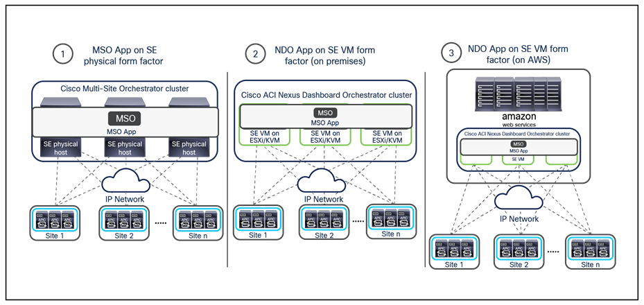
MSO cluster deployment on different Cisco Application Services Engine form factors
● Physical form factor: This essentially allows you to build a physical cluster of 3 server nodes and deploy the MSO microservices across them. A specific .iso file for the Cisco Application Services Engine is available for download on Cisco.com and can be installed on those bare-metal clustered servers.
● Virtual machine form factor (on-premises deployments): Two virtual appliance flavors are available for the CASE, one to be run on VMware ESXi hosts and the second on Linux KVM hypervisors.
● Virtual machine form factor (AWS public-cloud deployments): Cisco Application Services Engine can be deployed in the public cloud using a CloudFormation Template (CFT) for AWS (a specific .ami file is available for the CASE virtual appliance). This allows you to deploy a cluster of three CASE VMs directly in a specific AWS region.
Note: Independently from the specific CASE form factor of choice, the MSO application is installed the same way on top of a three-node CASE cluster, so the same considerations for cluster resiliency mentioned for the VM-based MSO installation continue to be valid here. Also, the recommendation is to deploy the MSO application on CASE starting from Cisco Application Services Engine Release 1.1.3, which also requires a minimum Cisco Multi-Site Orchestrator Release 3.0(2).
The same latency considerations shown in Figure 132 also apply when deploying MSO as an application running on a CASE cluster.
For more information on the installation of a Cisco Application Services Engine cluster and of the MSO application running on top of it, please reference the documents below:
Appendix C: Multi-Site and GOLF L3Out connections
Even when GOLF is used to connect to the external Layer 3 domain, you can deploy a dedicated or a shared pair of GOLF routers to serve different fabrics, as shown in Figure 133.
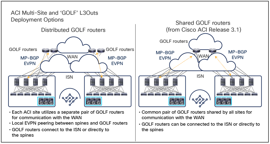
Dedicated or shared pairs of GOLF routers
Note: The shared GOLF devices design on the right is supported from Cisco ACI Release 3.1(1).
In the dedicated GOLF devices use case, the spine nodes deployed in each fabric establish MP-BGP EVPN adjacencies with the local GOLF routers to be able to exchange reachability information and build the VXLAN tunnels required for the north-south data-plane communication.
The scenario using dedicated GOLF devices raises the following deployment considerations when a common Layer 3 infrastructure is used for north-south and east-west communication.
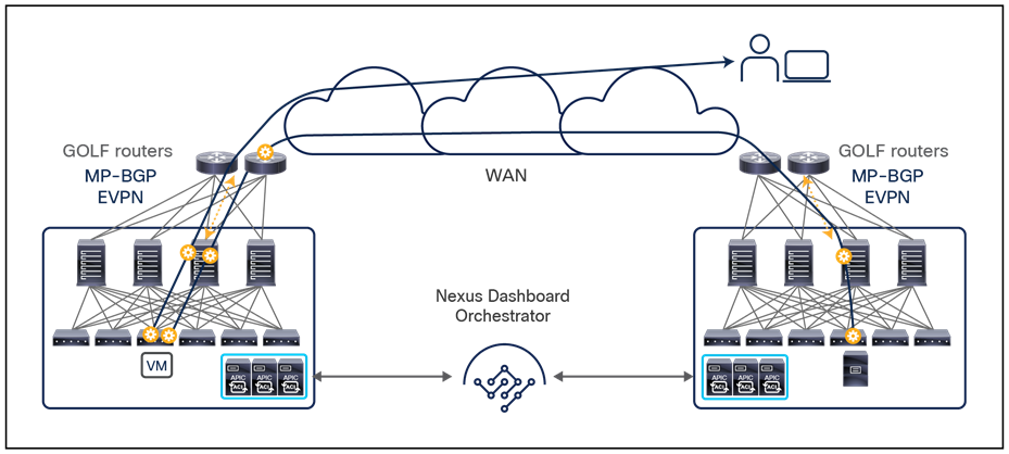
Common Layer 3 infrastructure for east-west and north-south traffic
As shown in Figure 134, the GOLF routers in this case play a double role: as the VTEP for performing VXLAN encapsulation and decapsulation for north-south communications between the Cisco ACI fabric and the WAN, and as the means for performing standard Layer 3 routing for east-west intersite flows. Two approaches are possible, as described in Figure 135: sharing the same set of physical connections between the spine nodes and GOLF routers to carry both types of traffic, or using dedicated connections for each type of communication.
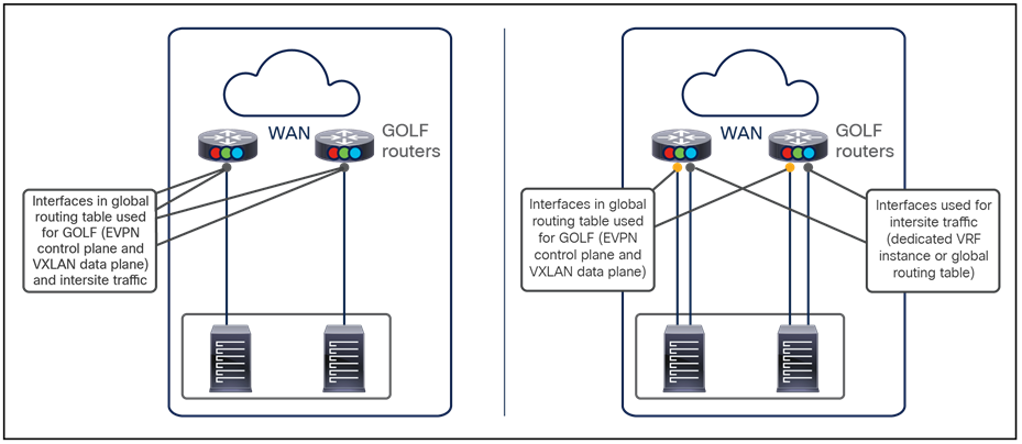
Shared or dedicated physical connections for GOLF and Multi-Site deployments
Note that to establish MP-BGP EVPN adjacencies between the spine nodes and the GOLF routers, the GOLF interfaces must be part of the global routing table routing domain. Hence, the use of a single set of physical connections shown on the left side of Figure 135 implies also that the Multi-Site traffic will be routed in that global table routing domain and cannot be forwarded as part of a different VRF instance.
Note: It could technically be possible to leak selected routes from the global table into a dedicated VRF, if the desire is to carry east-west Multi-Site traffic in a dedicated routing domain. Doing so would, however, increase the complexity of the configuration and expose to potential issues due to misconfigurations.
The only clean way to carry the Multi-Site traffic in a dedicated VRF instance is to use separate physical interfaces, as shown on the right side of Figure 135. This approach often is important with Multiprotocol Label Switching (MPLS) VPN WAN services, because intersite traffic should not be carried in the global routing table.
Regardless of whether the same or dedicated physical interfaces are used for GOLF and intersite communications, before Cisco ACI Release 3.2(1) the Cisco ACI Multi-Site design mandates the definition of two separate L3Out connections in the infra tenant to be used for GOLF (north-south) and Multi-Site (east-west) types of communication. In the specific case in which the same physical interfaces are used for both types of traffic, you must follow these configuration guidelines:
● Define the same router ID for the spine nodes in both infra L3Out connections
● Define the same set of logical interfaces and associated IP addresses
● Associate both L3Out connections with the same overlay-1 VRF instance
● Define the same OSPF area on both L3Out connections
Starting from Cisco ACI Release 4.2(1), it is possible to define the same infra L3Out to be used for GOLF and Multi-Site traffic. This approach simplifies the configuration, and it is desirable when the same set of physical interfaces are used for both types of communication.
Since the first Cisco ACI Multi-Site Release 3.0(1), the deployment of GOLF L3Outs has allowed the announcing of host-route advertisements toward the external network. As shown in Figure 136, and as previously discussed in the border leaf L3Outs section, the use of host-route advertisement is useful in deployments in which a bridge domain is stretched across separate fabrics, because it permits properly steering of the ingress traffic toward the site at which a specific destination endpoint is located.
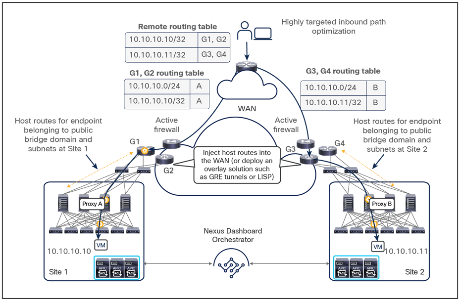
Ingress path optimization using host-route advertisements
This approach helps ensure that traffic can always be sent through the local firewall node active in the same site at which the endpoint is located.
It is important to highlight that enabling host-route advertisement for stretched bridge domains is not only an optimization but a mandatory configuration when deploying GOLF L3Outs in conjunction with ACI Multi-Site.
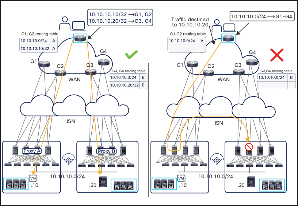
Ingress traffic drop without host-route advertisements on GOLF L3Outs
As shown on the right side of Figure 137, without host-route advertisement, a remote WAN router may receive routing information for the stretched bridge domains from all the GOLF routers. As a consequence, ingress traffic may be steered toward site 1 even if the destination endpoint is located in site 2. This suboptimal behavior can be supported when deploying border leaf L3Outs; however, in the current Cisco ACI Multi-Site implementation with GOLF L3Outs, suboptimal ingress flows are dropped by the spines in the destination site because of the lack of proper translation table entries. As a consequence, the only working option when deploying GOLF L3Outs consists in leveraging host-route advertisement to ensure inbound traffic is always optimally delivered (as highlighted in the scenario to the left in Figure 137).
Note: If the BDs are not stretched, those considerations do not apply because the assumption is that the IP subnet for each non-stretched BD is always and solely advertised by the spine nodes of the fabric where the BD is deployed.
Document history
| New or Revised Topic |
Described In |
Date |
| Removed most of the content related to CloudSec, because the functionality is going to be deprecated and added a link to the security advisory notice. |
Cisco ACI Multi-Site and site-to-site traffic encryption (CloudSec) |
August 1, 2024 |
| Multiple edits and updates. |
Various sections |
August 1, 2024 |
| Refreshed the content throughout the entire document to replace MSO with NDO |
|
November 09, 2022 |
| Added a new section covering Nexus Dashboard deployment considerations |
November 09, 2022 |
|
| Added coverage for new template types introduced in NDO release 4.0(1) |
New Template Types Introduced on NDO 4.0(1) Software Release section |
November 09, 2022 |
| Added a section about NDO operational enhancements (template level functionalities) |
November 09, 2022 |
|
| Refreshed the content relative to brownfield integration scenarios |
November 09, 2022 |
|
| Moved old MSO cluster deployment considerations to Appendix B |
November 09, 2022 |
|
| Moved content related to GOLF L3Out connections to Appendix C |
November 09, 2022 |