Cisco AI Inference White PaperArchitecture for Wide Area Networks
Available Languages
Bias-Free Language
The documentation set for this product strives to use bias-free language. For the purposes of this documentation set, bias-free is defined as language that does not imply discrimination based on age, disability, gender, racial identity, ethnic identity, sexual orientation, socioeconomic status, and intersectionality. Exceptions may be present in the documentation due to language that is hardcoded in the user interfaces of the product software, language used based on RFP documentation, or language that is used by a referenced third-party product. Learn more about how Cisco is using Inclusive Language.
This blueprint describes how to implement AI Inference Routing across a provider's wide area network, whether that provider is a service provider, neocloud provider, or AI inference provider. It shows how a converged network connects distributed inference sites, from a single edge cabinet to a regional facility, with each other and with the enterprises and consumers that depend on them, placing, routing, securing, and assuring AI workloads across edge, regional, and core locations on demand.
It is a high-level design (HLD) intended for network architects, transport and service planning teams, and operations leadership. It makes explicit technology choices so it can serve as the basis for a detailed low-level design and implementation guide.
The design covers the following solution domains:
● Datacenter Interconnect (DCI): Connecting inference sites to one another for model distribution, synchronization, and capacity pooling
● Enterprise Access: Extending inference services to business sites within their isolation and SLA boundaries
● Consumer Access: Steering subscriber inference traffic to the nearest suitable site
● Network Slicing: Providing differentiated performance and isolation for each class of inference traffic
● Resiliency: Protecting inference services against link, node, and site failures through layered fast reroute and failover
● Security and Sovereignty: Keeping traffic on trusted infrastructure and within required boundaries
● Assurance: Measuring network and AI service quality end to end, and verifying where requests were served
● Automation: Provisioning, optimizing, and remediating services through closed-loop, intent-based operations.
Table 1. Revision history
| Version |
Date |
Comments |
| 1.0 |
Current |
Cisco AI Inference Architecture for Wide Area Networks |
The technology choices in this document are drawn from and align to the following published Cisco designs, which should be consulted for protocol-level detail and configuration:
● Agile Services Networking (ASN)
● Cisco DCI Design
● Cisco Autonomous Networking
In scope: the Provider transport and service architecture connecting (a) distributed inference locations to each other (Datacenter Interconnect, DCI); and (b) enterprise and consumer demand to the inference endpoints with IP connectivity. The document covers slicing, assurance and automation for inference connectivity.
Out of scope: the internal GPU/accelerator fabric of each inference site, model lifecycle, and the AI application stack itself — these are treated as workloads that the network serves.
AI inference is moving from centralized experimentation into production applications that must respond quickly, protect sensitive data, and operate reliably. Because users, data, and compute are spread across different locations, no single inference site can meet every workload’s needs. The wide area network must connect these locations and help deliver the right service performance, security, and policy controls
end to end.
This blueprint presents a Cisco architecture for service providers and neoclouds to connect distributed inference infrastructure with enterprise and consumer demand. It treats each inference location as a data center and defines four placement tiers: far edge, metro edge, central edge, and external cloud or peering. Workloads can use the tier best suited to their latency, capacity, cost, data gravity, and sovereignty requirements.
The architecture combines routed optical transport, SRv6 with micro-segment identifiers, Flex-Algo, traffic engineering, and BGP-based VPN and EVPN services. These technologies support both data center interconnect between inference sites and access from enterprise VPNs, broadband, and mobile networks. They also enable providers to apply different connectivity policies for workloads with distinct requirements, including low latency, high throughput, resilience, isolation, and jurisdictional constraints.
The blueprint addresses the operational requirements of an inference service as well as its connectivity. It describes layered security for traffic, platforms, and inference endpoints, alongside observability that correlates user experience with network, gateway, and available compute signals. Automation supports service provisioning, slicing, path selection, capacity planning, and policy-governed remediation. Measures such as time to first token and inter-token latency help providers assess the delivered experience, while the service boundary determines which performance commitments they can support. For external models, the provider can report on its monitored network domains; broader commitments require visibility and shared operational responsibility beyond those domains.
The proposed evolution is incremental: establish measurement and visibility, connect enterprise environments and inference locations, add optimization and security, and then expand to sovereign inference services with defined performance objectives. This gives providers a practical path from transport connectivity to a managed inference service—one that can evolve as customer demand, compute placement, and workload requirements change.
2. Introduction and problem statement
Artificial Intelligence is moving rapidly from experimentation to operational deployment. What began as isolated pilots, innovation projects, and proof-of-concept initiatives is now becoming embedded into the core operating fabric of enterprises. Across industries, organizations are integrating AI into mission-critical workflows: customer service agents that handle real-time interactions, enterprise copilots that augment employee productivity, network automation systems that accelerate operations, fraud detection platforms that analyze behavior patterns, financial analytics engines that support decision-making, and digital twins that model complex physical and business environments.
At the center of this transformation is AI inference: the real-time execution of trained AI models against live enterprise data, user prompts, events, transactions, and operational signals. Inference is where AI delivers business value. It is the point at which trained models — including large language models, small language models, domain-specific models, and multimodal foundation models — are applied to real-world tasks and decisions.
While AI model training remains largely concentrated among hyperscalers, AI-native companies, and organizations with access to massive GPU capacity, inference is evolving very differently. It is becoming more distributed, more latency-sensitive, more security-critical, and more tightly coupled to enterprise operations or consumer demands. Unlike training, which can often be centralized and performed asynchronously, inference must frequently occur close to users, applications, data sources, and business processes. It must respond in real time, preserve data privacy, comply with sovereignty requirements, and deliver predictable performance under production conditions.
This shift creates a strategic inflection point for Providers (service providers and newly evolving cloud providers). AI inference is not simply another cloud compute workload, nor is it only a matter of hosting GPUs in regional data centers. As enterprises and consumers increase AI adoption, inference becomes part of the digital infrastructure they depend on every day.
● It is content-sensitive, because prompts and responses may include proprietary, regulated, or personally identifiable information.
● It is constrained by data sovereignty, because enterprises and governments increasingly require AI processing to remain within defined jurisdictions.
● It is security-exposed, because AI introduces new attack surfaces such as prompt injection, data leakage, model misuse, and adversarial behavior.
● It is operationally critical, because AI agents and applications are beginning to participate directly in customer engagement, financial operations, industrial workflows, healthcare processes, and network control.
● And it is increasingly distributed, because enterprise and consumer use cases require inference capacity at, central edge, metro edge, far edge, and sometimes on-premises locations.
Providers (Services Providers and Neo Cloud Providers) are uniquely positioned to address these requirements. They,
· operate distributed infrastructure footprints,
● maintain trusted relationships with enterprise and public-sector customers as well as consumers,
● understand regulated operating environments,
● and most importantly, own and operate the network fabric that connects users, data, applications, and compute.
These assets allow providers to approach AI inference not as a commodity GPU-hosting business, but as a secure, sovereign, resilient, and SLA-driven AI execution platform.
The opportunity, therefore, is not merely to participate in the AI infrastructure market. It is to redefine the role of the provider (Service and Cloud) in the AI era. By combining distributed compute, deterministic connectivity, policy-based routing, sovereignty enforcement, AI-specific security, observability, and lifecycle services, telecom operators can create a differentiated Inference Fabric: a carrier-grade platform designed to execute AI workloads where enterprises need them, with the performance, control, trust, and resilience that production AI demands.
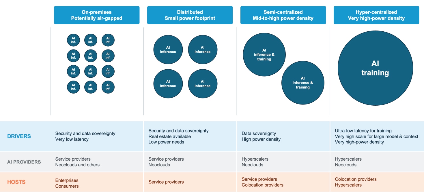
AI Inference market forces
2.2. The shift from centralized to distributed inference
The first wave of generative AI was built and consumed in a centralized model: a handful of hyperscale data centers trained enormous models, and inference requests traveled from anywhere in the world back to those same facilities to get an answer. That architecture worked reasonably well for chatbots and batch-style workloads, where a few hundred milliseconds of round-trip latency is invisible to the end user. But the next generation of AI applications breaks this model entirely, and it breaks it on physics grounds, not just business preference.
2.2.1. Why centralized inference doesn't always fit to AI-native applications
Sovereignty and regulations: There's a regulatory and sovereignty dimension. As AI moves into healthcare, finance, public safety, and government use cases, data residency and jurisdictional control become hard requirements rather than nice-to-haves. Distributed inference lets workloads run within a specific region, country, or even a specific facility, satisfying compliance requirements that a single centralized cloud footprint structurally cannot.
Economics: There's also an economic argument: centralized AI factories are enormously expensive and capacity-constrained. GPU supply is scarce and unevenly distributed. A purely centralized model means peak demand in one application competes directly with peak demand in every other application for the same limited pool of compute, creating congestion, higher token costs, and stranded capacity elsewhere in the system. Treating many smaller, distributed sites as a single orchestrated pool of capacity smooths out these peaks and dramatically improves utilization.
Application requirements: Real-time voice agents, AI-augmented video calls, autonomous robotics, industrial vision systems, and agentic copilots embedded in physical or interactive environments are fundamentally latency-bound. A voice assistant that pauses for 400 milliseconds before responding feels broken in a way a chatbot that takes a few extra seconds does not. A robot at a factory, home or autonomous vehicle making safety-relevant decisions cannot tolerate the variability introduced by a 2,000-mile network hop to a centralized cloud region. As these applications scale from thousands of users to hundreds of millions of users, agents, and devices, the laws of networking — not the limits of GPU compute — become the binding constraint. You cannot compress the speed of light; you can only move the compute closer to where the data and the user actually are.
Data gravity and bandwidth: There's an equally hard constraint: bandwidth and data gravity. Vision, video, and sensor-heavy workloads generate enormous volumes of data at the edge. Hauling all of that raw data back to a centralized AI factory for processing, then sending results back out, multiplies network costs and congests backbone capacity. It's far more efficient to run inference where the data is created and only move the much smaller distilled output — text, embeddings, decisions — across the long haul. This is the same logic that drove Content Delivery Networks (CDNs) to distribute video caching to the edge twenty years ago; AI inference is now following the identical curve, just with a far more compute-intensive payload.
2.2.2. Why wide area networking is key for AI inference
Wide Area Networking (WAN) is becoming a critical foundation for AI inference because inference workloads (Clients, AI-GWs and LLMs) are increasingly distributed across data centers, cloud platforms, edge locations, and end-user devices. AI inference requires moving volumes of data between the point where information is generated and the infrastructure where models are hosted. Consequently, network performance directly affects response time, reliability, cost, and user experience.
AI inference connectivity requirements are ultimately defined at the application and solution level, and these requirements determine the capabilities that the underlying Wide Area Network (WAN) must provide. Different use cases place different demands on connectivity. Real-time applications such as autonomous systems, industrial automation, fraud detection, and interactive assistants require very low and predictable latency, low jitter, minimal packet loss, and high availability. Other workloads, including medical imaging, video analytics, and recommendation systems, may prioritize sustained bandwidth, high throughput, data-transfer capacity, and predictable processing windows. A WAN is therefore essential for connecting users, data sources, cloud platforms, edge locations, and inference infrastructure in a way that supports the performance and operational needs of each solution.
Networking Service-Level Agreements (SLAs) should reflect these application-level requirements rather than rely on a single generic connectivity standard. SLAs may define measurable commitments for end-to-end latency, bandwidth, availability, packet loss, incident response, failover, and recovery time across the complete path—from the user or data source, through the WAN and cloud interconnect, to the inference endpoint. SLA-backed connectivity enables organizations to provide consistent application performance and align network behavior with the business criticality of each AI service.
AI Inference connectivity requires direct peering or private connectivity to multiple cloud providers. This allows organizations to access inference endpoints hosted by public clouds, sovereign clouds, or specialized AI infrastructure without requiring those endpoints to be deployed inside the of Provider network. Peering at suitable WAN locations can reduce latency, avoid unnecessary backhauling, improve resilience, and provide flexibility to select inference resources based on performance, cost, model availability, and jurisdiction. Policy-based routing can direct workloads to the most appropriate endpoint.
Data sovereignty is another solution-level requirement that the “network” must enforce. Regulations and organizational policies may require data to remain within a particular country, region, or legal jurisdiction. The network must support sovereignty-aware routing, data residency controls, segmentation, encryption, security and access policies so that data is processed only in approved locations and through authorized connectivity paths. In this way, WAN networking makes it possible to satisfy the combined requirements of AI applications: performance, scalability, reliability, security, multi-cloud access, and sovereignty.
2.2.3. Why providers are uniquely positioned to host this layer
Providers (Service Providers, and Neo Cloud Providers) are not incidental candidates for the AI inference opportunity. They are structurally among the best-positioned players in the AI value chain to solve the distribution, connectivity, gravity, performance, sovereignty, and trust challenges that will define
production AI.
First, they already operate the physical footprint required for distributed inference. Providers own and manage geographically distributed infrastructure, including central offices, mobile switching centers, metro sites, regional data centers, points of presence, and cell sites. This infrastructure was originally built to deliver voice, mobile, broadband, and enterprise connectivity services, but it now maps closely to where low-latency AI inference needs to run. Many of these facilities can support small-to-medium-scale GPU clusters optimized for inference, enabling AI compute to be placed closer to enterprise users, applications, and data sources without requiring hyperscale data center build-outs.
Second, providers control the network itself, not just compute sitting on top of it. Latency, jitter, bandwidth, packet loss, traffic prioritization, and path resilience are network-layer properties. A provider that owns both the transport network and distributed inference infrastructure can engineer end-to-end performance across the full AI delivery path. This includes packet routing, traffic engineering, deterministic transport, network slicing, edge placement, security enforcement, and SLA assurance in a way that cloud providers relying on third-party network capacity cannot fully replicate.
Third, providers already operate with carrier-grade reliability and operational discipline. They have the monitoring systems, service assurance processes, field operations, security practices, and SLA culture required to run mission-critical infrastructure at national and regional scale. That maturity is essential as AI inference becomes embedded into business-critical workflows, where enterprises will expect predictable performance, resilience, observability, and rapid incident response rather than best-effort API availability.
Fourth, providers have long-standing relationships with both enterprise and consumer customers. They have served enterprises for decades across voice, data, connectivity, managed services, mobility, security, and cloud access. In regulated industries such as finance, healthcare, government, energy, and critical infrastructure, this trust is especially important. Enterprises already rely on providers for foundational digital services, making them natural partners for AI inference services that require accountability, contractual SLAs, compliance alignment, and local operational support.
Fifth, providers are strongly positioned around data privacy and sovereignty. AI inference often processes sensitive prompts, proprietary business data, customer information, operational telemetry, and regulated content. Because many providers are national or regional entities operating under local regulatory frameworks, they have both the credibility and the technical ability to enforce sovereignty requirements. They can support policies that keep inference execution within approved regions, restrict network paths across jurisdictions, and provide auditable controls for data handling, model access, and service delivery.
Finally, this represents a genuine new revenue opportunity for an industry by becoming the execution substrate for AI-native services, rather than simply the connectivity layer beneath them, providers can monetize capabilities that are uniquely theirs: locality, latency, secure transport, deterministic performance, sovereignty, resiliency, and trusted operations. These assets allow providers to transform inference from a simple compute offering into a secure, sovereign, resilient AI execution platform.
2.3. Provider use cases for AI Inference
Production-scale inference is becoming the dominant workload and a critical design point for next-generation network infrastructure. Many emerging AI applications will be served almost every location of the network. They require inference to happen closer to users, devices, cameras, robots, vehicles, and enterprise locations in order to meet strict requirements for latency, jitter, bandwidth, cost, data locality, and service reliability.
Table 2. Networking drivers for AI Inference use cases
| Driver |
Use cases most affected from the driver |
| Deterministic latency |
Voice AI, conversational agents, translation/lip-sync, physical AI, robotics, AVs, AR/XR |
| Bandwidth |
Vision AI, CCTV, smart spaces, public safety, retail loss prevention, video analytics |
| High concurrency/ |
GenAI, multimodal LLMs, image/video generation, voice assistants, media AI |
| Hyper-personalization |
Agentic web, ecommerce recommendations, AI media, ad insertion, personal assistants |
| Safety and split-control loops |
Physical AI, robots, drones, AVs, industrial automation |
| Economics and monetization |
AIaaS, token-as-a-service, agent-as-a-service, enterprise inference platforms |
For providers, these use cases represent a major opportunity to evolve from connectivity into distributed AI services. Their existing footprint of fiber, access connectivity, central offices presence, regional sites, and trusted customer relationships give them a strong position to host and orchestrate AI workloads closer to where data is generated and consumed.
The following table summarizes the key AI use cases that require or strongly benefit from distributed inference and explains the technical and business reasons behind each requirement.
Table 3. AI Inference use cases and requirements
| AI Inference use case |
Use case requirements |
Networking requirement |
| Real-time |
Data gravity: Audio streams and conversational context are generated close to the user, so processing them nearby reduces response delay. |
Low and predictable latency, low jitter and packet loss, session continuity, high availability, encryption, and SLA-backed response, failover, and recovery targets. |
| Real-time language translation and lip-sync |
Data gravity: Speech, video, and personalization context are generated near the user. |
Low latency and jitter, high throughput for audio and video, packet-order preservation, synchronization support, and strict latency and availability SLAs. |
| Real-time video generation and video augmentation |
Data gravity: Video streams and per-viewer context are close to the viewer or content source. |
Ultra-low RTT, tightly controlled jitter, high bandwidth, predictable egress capacity, rapid scale-out, and stringent latency and availability SLAs. |
| Vision AI for smart spaces, CCTV, public safety, and retail loss prevention |
Data gravity: Large volumes of raw video are generated at cameras and local sites, making local preprocessing more efficient. |
High local ingress capacity, edge processing, bandwidth-efficient backhaul, reliable event delivery, burst handling, data protection, and availability SLAs. |
| AR/XR and immersive experiences |
Data gravity: Scene understanding, user state, and rendering inputs are closely tied to the user’s physical location. |
Very low latency and jitter, high sustained throughput, reliable mobility support, and SLA-backed performance for interactive sessions. |
| Agentic web, ecommerce, and recommendation apps |
Data gravity: User profiles, transaction data, and personalization context are distributed across regions. |
User-near latency, elastic bandwidth, reliable API connectivity, intelligent load balancing, multi-cloud peering, encryption, and policy-based routing. |
| AI for media: ad insertion and video augmentation |
Data gravity: Content and session metadata are close to the viewer. |
Low-latency session connectivity, high concurrency, egress and backhaul optimization, predictable bandwidth, content protection, and availability SLAs. |
| Multimodal GenAI/LLMs /image and video generation |
Data gravity: Large prompts, documents, images, and videos may originate across multiple regions. |
High-throughput connectivity, scalable capacity, low transport and queueing latency, multi-cloud peering from WAN locations, traffic engineering, and capacity and failover SLAs. |
| AI APIs for physical AI and enterprise apps |
Data gravity: Enterprise and physical-world data are distributed across sites, devices, and applications. |
Secure and observable API connectivity, tenant isolation, consistent availability and recovery SLAs, direct peering to multiple cloud providers, and sovereignty-aware routing. |
2.4. Every inference location is a datacenter
This blueprint adopts a single, unifying assumption requested for the design: each distributed inference location is treated as an AI Inference Datacenter. An AI Inference DC may be a handful of accelerator servers in a far-edge cabinet, a modest GPU pod in a metro aggregation site, or a larger regional facility with a leaf/spine fabric. Regardless of size, each datacenter has the same network needs: a way to be interconnected with other datacenters (DCI), and a way to be reached by the customers that the inference serves.
1. DCI between DCs — connecting the distributed inference locations to one another for model distribution, state and cache synchronization, backend/collective traffic, and capacity pooling across sites.
2. Reachability to inference — connecting customers (enterprise VPNs) and consumers (wireline and wireless subscribers) to the nearest or most appropriate inference endpoint.
2.5. AI Inference over WAN - Design goals
The architecture is shaped by the following goals, inherited from the ASN Metro design and specialized for inference:
● Any-to-any, any-place service placement. Inference can be terminated at any point in the metro — access, aggregation, edge or central — without redesigning the network.
● A single converged underlay carrying DCI, enterprise and consumer traffic, rather than parallel networks.
● Isolation through network slicing, so inference traffic gets the treatment it needs and is protected from — and does not harm — other services.
● Built-in, measurable assurance of the SLA between consumer and inference and between datacenters.
● Full lifecycle automation, so inference connectivity can be provisioned, changed and assured at machine speed.
● Scale and simplicity, using address summarization and a minimal protocol set so the network grows to tens of thousands of nodes without operational explosion.
3. Reference architecture overview
The Cisco AI Inference Architecture for WAN focuses how Service Providers and Neo Cloud can deliver AI inference with a programmable network across their footprint. A single Agile Services Network interconnects central and metro inference data centers, edge inference nodes, enterprise sites, and consumers over any access network. This enables AI workloads to run close to users and data sources while also supporting connectivity to centralized AI infrastructure and externally hosted inference endpoints.
The network uses Segment Routing over IPv6 (SRv6) with micro-Segment Identifiers (uSID) to provide programmable traffic steering and service-aware connectivity. Flex-Algo-based policies allow the provider to tailor network behavior for different inference needs, including steering towards optimum cost models, low-utilization GPU infrastructure, providing high-throughput interconnect (DCI), and provide sovereign, low latency, secure or isolated connections for AI services.
The architecture supports both east-west and north-south inference traffic. East-west traffic connects distributed inference locations and carries model movement, backend processing, synchronization, and data exchange. North-south traffic connects users, applications, enterprise sites, and inference endpoints. Separating these traffic patterns through programmable routing policies helps prevent contention and ensures that application-specific performance requirements are maintained across the inference path.
Service creation and operation are supported by intent-based automation and orchestration. Crosswork Network Controller and Network Services Orchestrator (NSO) can be used for service provisioning, path computation, policy deployment, slice orchestration, and closed-loop remediation. Assurance and observability continuously correlate network and AI performance, including latency, jitter, packet loss, path health, time to first token, inter-token latency, and inference flow loss. This allows the provider to identify whether an issue originates in the network, the AI gateway, or the model infrastructure.
The underlying routed optical network, timing services, and deterministic backend connectivity provide the transport foundation for these services. Security and policy controls enforce traffic isolation, micro-segmentation, Distributed Denial-of-Service (DDoS) protection, Edge Protect, and transport security across the AI inference path. The architecture is also designed to support Post-Quantum Cryptography (PQC)-ready security. Together, these capabilities allow the providers to deliver scalable, observable, secure, and policy-driven AI inference connectivity across distributed network locations.
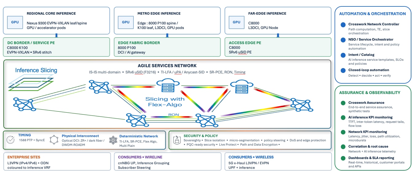
Cisco AI inference for WAN reference architecture
DCI: Datacenters exchange model artefacts, embeddings/vector caches, key-value caches for disaggregated serving, and — where inference is sharded across sites — backend collective traffic. This traffic is bandwidth-heavy and, for tightly coupled cases, latency- and loss-sensitive. It is carried on a high-throughput, optionally bandwidth-guaranteed slice
Access to inference: Enterprise sites reach inference through their IP VPNs; consumers reach inference through their broadband or mobile service. This traffic is requests SLA for interactive use and must be steered to the correct inference endpoint while honoring the customer's isolation and SLA.
3.1. Transport network layered technology stack
The architecture is built from the following layers. Each is justified in detail in later sections; the table summarizes the explicit choices made by this blueprint.
Table 4. Layered technology choices for the blueprint
| Layer |
Chosen technology |
Role for inference |
| Physical/optical |
Routed Optical Networking (DCO ZR/ZR+ pluggables; dark fiber, P2P DWDM, ROADM) |
Collapses transport into the router; high-capacity, low-power mini-DC interconnect. |
| Underlay data plane |
SRv6 with micro-SID (uSID), |
Summarizable, IPv6-native, congruent service+transport; scales to many datacenters and services |
| IGP/topology |
IS-IS, multi-domain with summarization at |
One link-state plane; domains added per metro/region as inference grows. |
| Traffic engineering |
Flex-Algo (intent slices) + |
Realizes per-inference-slice paths and deterministic backend paths. |
| Overlay services |
BGP EVPN (ELAN/VPWS/E-Tree) and L3VPN/mVPN |
DCI between datacenter; enterprise and consumer reachability to inference. |
| Edge/subscriber |
MSE (Multi Service Edge), cnBNG (CUPS), |
Terminates Enterprise and consumers and scales inference sites as leaf/spine fabrics. |
| Assurance |
SR-PM (TWAMP-Light), PTP G.8275.1 + SyncE, Crosswork Assurance/CA- sensors and CA User Experience |
Continuous, measured SLA for inference paths and slices. |
| Automation |
Crosswork (CNC, Planning, HCO, |
Closed-loop provisioning, assurance and remediation of inference connectivity. |
4. Placement of AI Inference in the WAN
A central question for the Providers is where to place inference and how to interconnect it to needed users with a requested SLA. Cisco AI Inference architecture defines a four-tier placement model for inference datacenters.
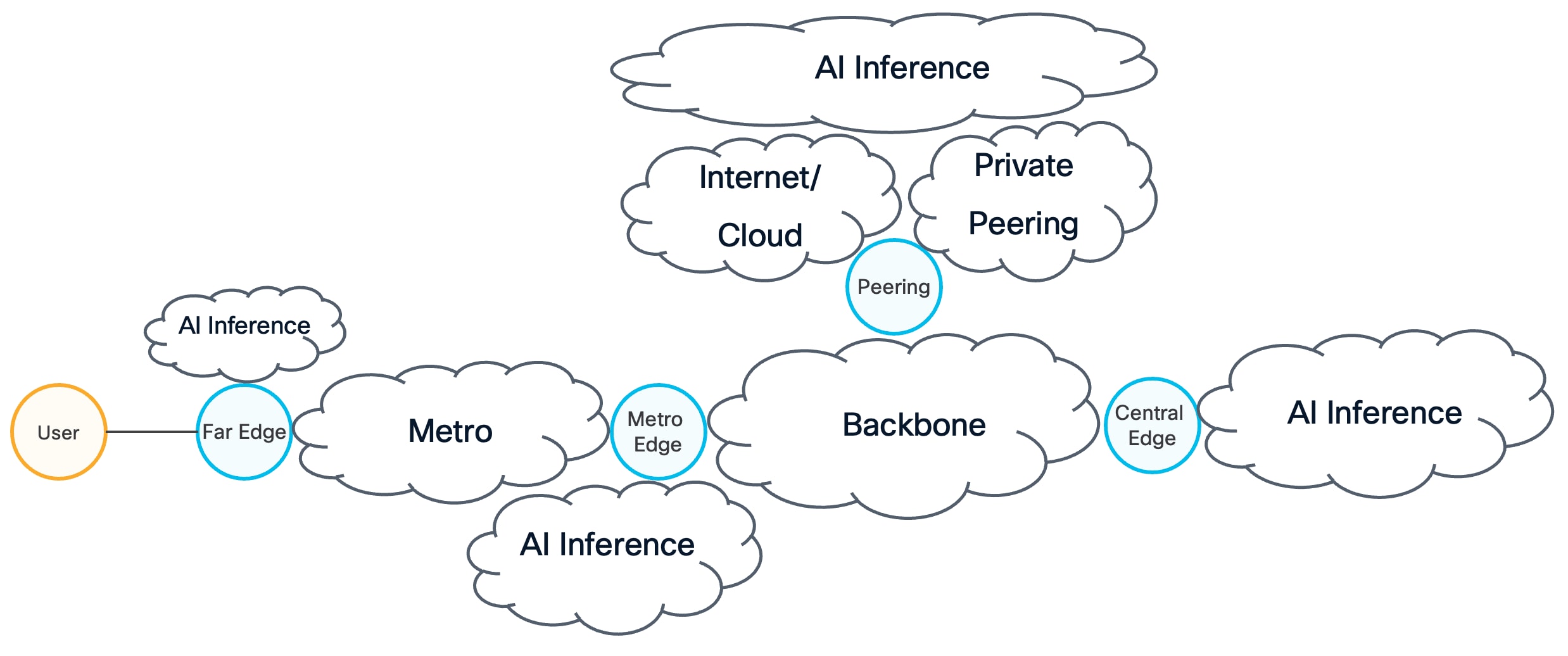
AI Inference placement at provider networks
4.1. A Four-tier distributed inference model
Table 5. Inference placement tiers in the metro.
| Tier |
Where |
Typical platforms |
Inference role |
| Far-edge |
Access site/cabinet, closest to users |
C8011/C8712 PE with a |
Latency-critical, lightweight models; caching/first-hop inference. |
| Metro Edge |
Aggregation or |
Edge Fabric: Cisco 8000 P100, |
Mainstream interactive inference for a metro; bulk of consumer serving. |
| Central Edge |
Regional/central office |
Cisco 8000 Modular, Nexus 9300 at dense GPU pods |
Heavy models, model hosting, |
| Peering |
Regional or Distributed peering |
Cisco 8000 P100, K100 at |
Any model not hosted at |
AI inference cannot be generalized so that does not have a single optimal placement. The right placement depends on the application’s requirements such as token cost, data gravity, workload size, concurrency, infrastructure utilization, sovereignty constraints, and latency. The four-tier model enable providers with a practical way to distribute inference capacity according to these requirements while maintaining a consistent WAN-based service model. It should be noted that application-level inference steering can choose and pick any location for potential inference processing across all available sites. It is also key to enable network capabilities to allow and ease such kind of dynamic connectivity.
Far-edge inference is valuable for latency-critical applications that require an immediate response, such as first-hop voice processing, industrial control, video event detection, and lightweight AI models or telecom network accelerations such as AI-RAN, AI-PON. Placing compact accelerator pods at access sites or cabinets keeps inference close to users and devices, reduces backhaul traffic, and improves response-time predictability. For providers, this creates an opportunity to use existing access infrastructure to deliver differentiated edge services. For neoclouds, it provides a way to extend AI capabilities closer to customers without building a large data center at every location.
Metro-edge inference provides a balance between proximity and scale. Metro sites can aggregate demand from multiple access locations while remaining close enough to support mainstream interactive applications, including conversational AI, recommendation services, translation, and media processing. Larger GPU pods at metro locations improve utilization and simplify operations compared with deploying compute at every access site. This tier also enables providers to offer regional performance SLAs and gives neoclouds a distributed platform for serving high volumes of users with lower latency and reduced transport costs.
Regional inference provides the capacity and economics required for heavy models, model hosting, capacity pooling, and large-scale workload management. Dense GPU deployments at regional or central-office locations can support multiple metros, absorb demand peaks, host larger models, and provide overflow capacity when edge resources are constrained. This placement is particularly beneficial for neoclouds because it supports efficient GPU utilization, centralized model operations, and multi-tenant service delivery. Providers benefit by anchoring these resources within their regional WAN and data-center interconnect infrastructure.
Together, the three tiers allow inference workloads to move between local execution, metro-scale serving, and regional capacity pools. This supports workload offload, failover, model selection, and policy-driven placement based on latency, capacity, cost, security, and data sovereignty. It also allows inference endpoints to remain outside the provider’s private network when appropriate, while being reached through controlled WAN connectivity and cloud peering as the fourth model
For providers, this model creates a joint opportunity to offer AI inference as an integrated network-and-compute service. The provider contributes distributed connectivity, traffic engineering, SLAs, security, and access to customer locations, while the neocloud contributes models, GPU capacity, and inference operations. The result is a flexible and scalable architecture that places each workload where it can meet its performance, economic, and regulatory requirements.
5. Foundations for AI Inference connectivity – Transport and DCI
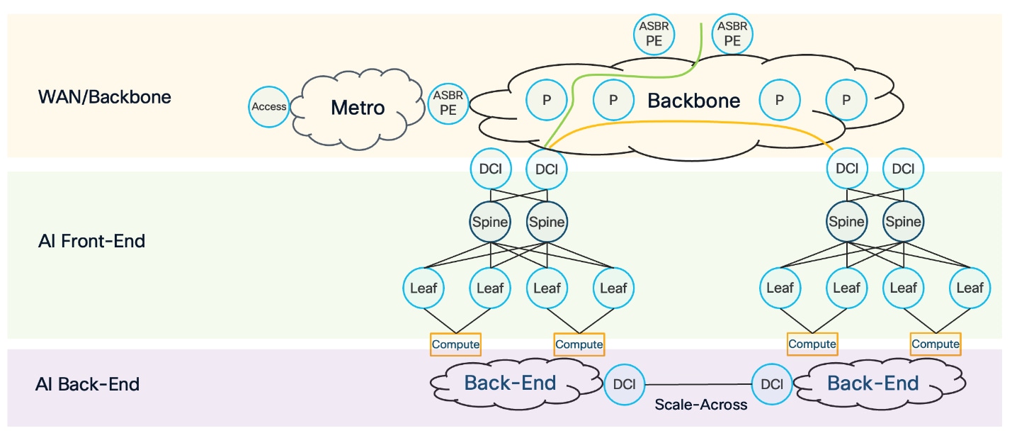
AI Inference Networking Layers
Figure 3 illustrates the end-to-end AI inference connectivity network built with Cisco Silicon One. The architecture connects edge sites through a WAN/backbone to distributed AI front-end and back-end environments. This design supports both user-to-inference connectivity and the high-volume data movement required between AI sites.
The WAN/backbone provides the multitenant transport foundation. It can use BGP Layer 3 VPN with VPNv4 or VPNv6, and BGP Layer 2 VPN with Ethernet VPN (EVPN), over an MPLS or IPv6 Segment Routing over IPv6 with micro-segment identifiers (SRv6 uSID) underlay. This combination supports traffic engineering, fast reroute, service isolation, and resilient connectivity. Cisco IOS XR is typically used in this part of the network.
This document focuses primarily on the backbone design and Layer 3 Data Center Interconnect (DCI) requirements for distributed AI inference.
The AI front-end connects inference traffic from the WAN to the data-center compute environment. It commonly uses BGP EVPN to provide multitenant Layer 2 and Layer 3 services, with either IPv4/IPv6 VXLAN or IPv6 SRv6 uSID as the underlay. Cisco NX-OS or SONiC may be used depending on the deployment model. The DCI provides the connectivity and service boundary between the WAN/backbone and the AI front-end.
The AI back-end provides connectivity to model-serving infrastructure and supports backend processing, model movement, and scale-across operations between AI sites. It may use BGP EVPN with VXLAN or SRv6 uSID to provide multitenant services, traffic engineering, and fast reroute. A dedicated DCI device may be used for backend scale-across connectivity, separate from the DCI device serving the AI front-end. This separation allows front-end access traffic and backend model or compute traffic to be engineered according to their distinct performance, capacity, and resiliency requirements.
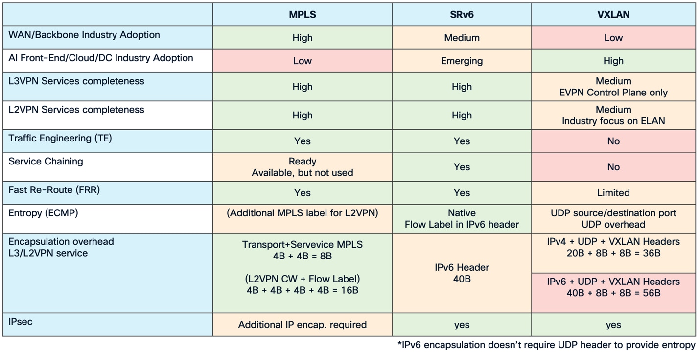
Transport protocol comparison for AI inference backbone
Figure 5 compares the available underlay encapsulation options and their adoption across the different network domains. Because this reference design focuses on backbone, Segment Routing with an IPv6 data plane and SRv6 uSID is used as the primary underlay technology in this design. Segment Routing with an MPLS data plane may also be used as an alternative
5.2. AI Frontend deployment options for AI Clusters
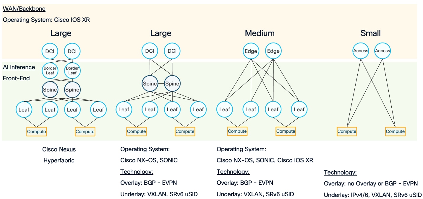
AI Frontend deployment options for AI clusters
Figure 6 illustrates three options for building the AI inference frontend and connecting it to the backbone: large, medium, and small deployments. The appropriate model depends on the geographic location, required scale, proximity to users, and whether the infrastructure is dedicated to AI inference or shared with other services.
5.2.1. Large AI Frontend
The large deployment follows a traditional spine-and-leaf architecture. It is primarily intended for regional or centralized locations and is typically connected to the backbone through a Data Center Interconnect (DCI).
The operating system may be Cisco NX-OS or SONiC. BGP EVPN serves as the overlay technology, with VXLAN as the primary data plane. The design also accommodates SRv6 uSID as an alternative data-plane option for future deployments. Cisco Nexus Hyperfabric is also a possible solution for large AI frontend deployments, providing a cloud-managed spine-and-leaf architecture.
5.2.2. Medium AI Frontend
The medium deployment is located closer to the metro or edge network and may extend toward the access network. This type of AI frontend may be shared with other services rather than being dedicated exclusively to AI inference.
In this model, the leaf devices connect directly to edge devices. The operating system may be Cisco NX-OS, SONiC or Cisco IOS XR. IOS XR can be used on the leaf when the same frontend infrastructure supports services that require IOS XR, such as deployments with specific timing, form-factor, or provider requirements.
Inference services may originate directly from the leaf or compute devices. Consequently, the AI inference frontend does not always need to be implemented as a separate network domain from the backbone.
5.2.3. Small AI Frontend
The small deployment is typically located in the access network or close to the metro edge, near the end user. In this model, the compute devices connect directly to the access device.
The access device combines the roles of the access switch and the leaf switch, providing a compact architecture for deployments that require AI inference resources close to the user.
5.3. AI Inference at WAN backbone
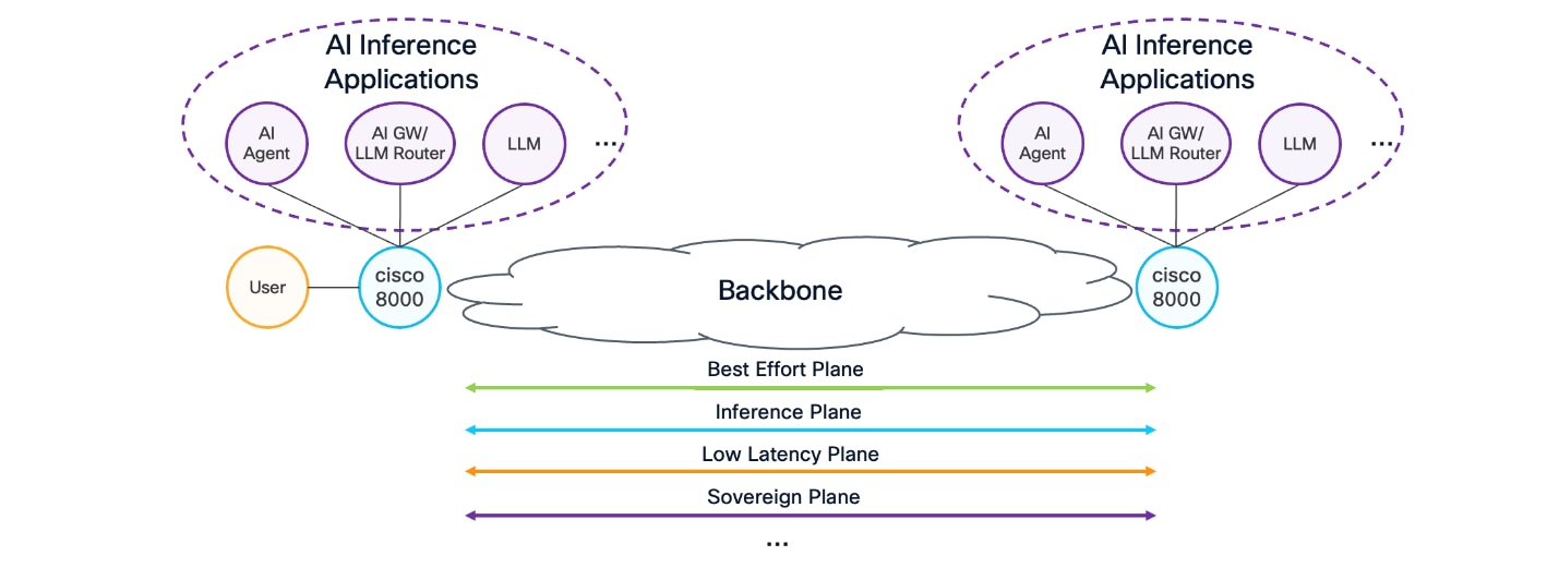
WAN backbone for AI Inference
For distributed AI inference, the backbone must support a multi-plane design. Each plane represents a distinct Service-Level Agreement (SLA) required by an inference workload or by another service operating across the shared backbone.
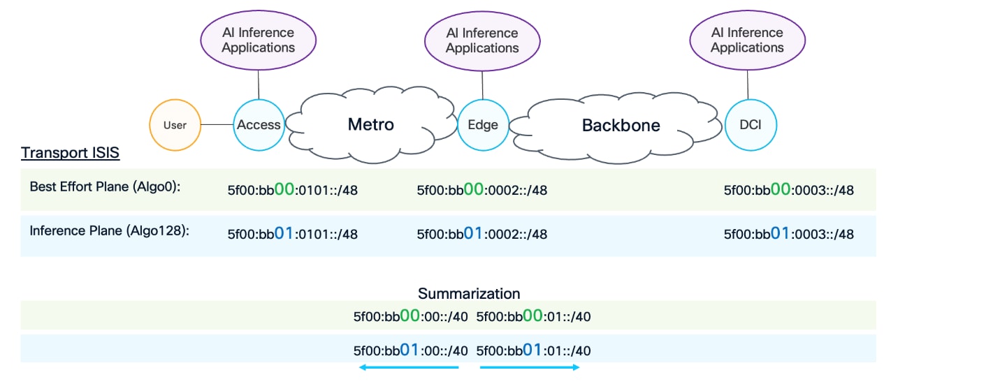
Figure 7 illustrates an example in which the backbone provides a best-effort plane alongside dedicated inference planes. These planes may be defined according to specific requirements, such as low latency, data sovereignty, or other application-specific SLAs.
Figure 7 also illustrates how different AI inference Applications/components can be connected across the network. The components shown are examples and may include an AI agent, an AI gateway, an LLM router, or an LLM service, etc. Each component may be deployed at a different location within the network.
The backbone must therefore provide a flexible, end-to-end transport service that can connect these distributed components according to their required service-level agreements. This capability is enabled through the multi-plane design described above.
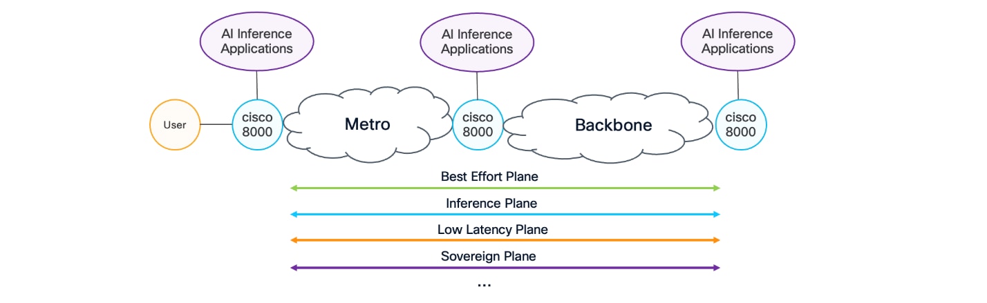
Inference placement at WAN backbone
Figure 8 illustrates that AI inference can be deployed anywhere in the network. It may reside within a network domain controlled by a single, such as the access, metro or backbone network. Alternatively, it may be located outside the provider’s domain and reached through private peering, cloud connectivity, or the Internet.
Design focuses on a distributed AI inference deployment within a single provider-controlled domain. In this model, the metro network effectively becomes an extension of the backbone. To support the SLA requirements of distributed AI inference, the multi-plane design described in the previous section must apply across both the metro and backbone networks.
This approach enables end-to-end service-level agreements to be supported through a consistent multi-plane design spanning the entire metro and backbone network.
The multi-plane design is implemented using Segment Routing Flexible Algorithms (Flex-Algo) within the network IGP. In this design, IS-IS is used as the IGP. Flex-Algo extends the standard shortest-path calculation, which is based primarily on link cost, by allowing paths to be computed according to additional constraints.
These constraints may include low latency, link affinity, secure links, sovereignty requirements, disjoint path, etc. Multiple constraints can also be combined to meet the requirements of a specific AI inference SLA.
Each network plane is associated with a Flex-Algo instance. The Flex-Algo computes the preferred path for that plane according to its defined constraints, ensuring that traffic is transported across the network in accordance with the SLA requirements of the corresponding AI inference service.
It is also important to note that each plane is precomputed by Flex-Algo and programmed into the forwarding of each network node or component before an AI inference request arrives. This ensures that the required network plane and associated SLA are available immediately, without introducing delays caused by real-time path computation or network programming.
5.4. Multiplane backbone - SRv6 uSID addressing and route summarization
Multi-plane backbone design for AI Inference connectivity
As discussed earlier, Cisco AI Inference WAN design uses Segment Routing over IPv6 (SRv6) with uSID. IANA has allocated the 5F00::/16 address block for use within the network. Although Unique Local Addressing (ULA), provider-assigned public IPv6 addresses, or other addressing schemes may be used for operational reasons, the recommended approach is to use the IANA-allocated block.
Figure 9 illustrates two Flex-Algo instances. The first is the default Flex-Algo, which represents the best-effort plane and computes paths using the standard IGP shortest-path calculation based on link cost. The second is an inference-plane Flex-Algo, shown as Flex-Algo 128. The Flex-Algo identifier used in this example is illustrative; multiple Flex-Algo instances may be deployed to support the different network planes described earlier.
Each plane uses a separate addressing block. In the example, the best-effort plane uses 5F00:BB00::/32, while the inference plane uses 5F00:BB01::/32. Separating the address space by plane allows the corresponding locators and routes to be identified, processed, and summarized independently.
The use of IPv6 as the data plane also supports network scalability through route summarization. At the boundary between the metro and backbone domains, the connecting node advertises summarized routes rather than the complete set of individual node routes. The metro and backbone therefore maintain independent IGP domains, with only the required summary routes redistributed between them.
A similar design can be implemented using IS-IS Level 1 and Level 2 domains. Regardless of the specific IGP hierarchy, an appropriate IPv6 addressing plan is critical to achieving effective summarization. Additional details about IPv6 addressing are provided in the appendix of this document.
In this example, each node is assigned a locator from the address block associated with each plane. The locator structure uses consistent values in the lower-order bits across the planes. For example, the leftmost router or access router in the metro use one locator value, while a router at the opposite side of the topology uses another. This structured allocation allows the node locators to be summarized at the metro–backbone boundary shown in Figure 8.
This addressing approach limits the number of routes exchanged between the metro and backbone domains while preserving independent operation of each IGP domain and each network plane.
SRv6 addressing details are available in IETF draft “draft-ietf-srv6ops-srv6addressing”.
5.5. SLA-based BGP Overlay Signaling and SRv6 Transport
BGP signaling for Inference connectivity
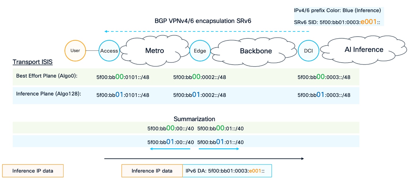
Figure 10 illustrates how BGP overlay signaling is associated with the SRv6 transport plane. On the right side of the figure, a DCI node connects the AI inference frontend to the backbone. The DCI advertises VPNv4 or VPNv6 reachability for the AI inference service, using SRv6 as the transport data plane. The advertised prefix may be installed in a VRF or in the global routing table (BGP IPv4/6 signaling is used instead).
The advertised route also carries a color value. In this example, the blue color represents a numeric value associated with the required SLA and indicates that the prefix must use the inference plane. The specific definition of each plane is described earlier in this document and may represent requirements such as low latency.
Together with the VPN prefix, the DCI advertises an SRv6 SID that provides the information required to encapsulate traffic and transport it across the network. The DCI also allocates an SRv6 function. This function represents the processing required at the DCI, including decapsulation and an IP lookup in the appropriate VRF to be able to forward the traffic toward the AI inference service.
The route advertisement therefore instructs the access node on the left side of the figure, where the user is connected, that traffic destined for the advertised IPv4 or IPv6 prefix must use the inference plane. As a result, traffic destined for the AI inference service follows the required SLA across the network from the user to the DCI and onward to the inference endpoint.
The lower portion of Figure 9 illustrates the data-plane operation. An inference packet travels from the user to the access device. Based on the destination IP prefix learned through the VPNv4 or VPNv6 route advertised by the DCI, the access device encapsulates the packet using SRv6 and steers it into the inference plane.
The different AI frontend-to-backbone interconnection models are described in the following sections of this document.
5.6. AI Inference frontend and backbone interconnect
Figure 6 illustrated three AI frontend deployment models: large, medium, and small. The deployment size is not the only factor that determines how the AI frontend connects to the backbone. The selected overlay and underlay technologies also influence how the interconnection is designed and how the requested service intent is signaled. The network must identify the required SLA and steer traffic onto the corresponding network plane.
The following section describes the connectivity models that can be used at any level of AI inference distribution. The overall design may combine multiple connectivity types depending on the placement of the AI inference components and their SLA requirements.
SLA requirements are typically bidirectional, and a different connectivity model may be used in each direction. The connectivity model may also vary between different segments of the application path. For example, the connection between a user and an LLM router may use one model, while the connection between the LLM router and the LLM model may use another.
5.6.1. Local connectivity
AI Inference cluster – Local connectivity
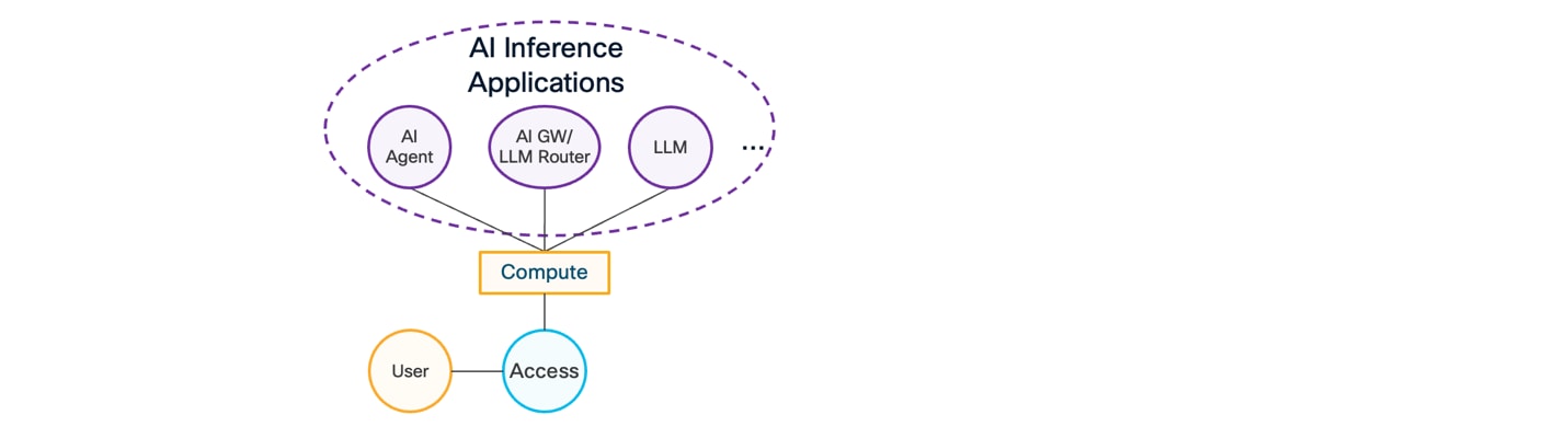
As shown in Figure 11, the local connectivity model connects two components through interfaces on the same router or network device. This model may support communication between a user and a nearby AI component, such as an AI agent, or between AI components such as an AI agent, AI gateway, and LLM router.
Because the communication remains within the same network device, no inter-device network transport is required. Traffic is handled through local forwarding and does not require the multi-plane design.
5.6.2. Remote connectivity - Direct IP Handoff
AI Inference cluster – Remote connectivity with Direct IP Handoff
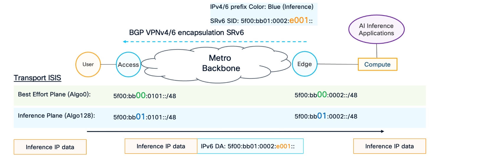
In the direct IP Handoff model, a remote AI component is connected through a routed IP interface to a network node whose routing context is either a VRF or the global routing table. This approach is typically associated with the small AI frontend deployment shown in Figure 5, where compute devices connect directly to the access or edge device.
As shown in Figure 11, the access device signals the requested SLA through a BGP VPNv4 or VPNv6 route by applying the appropriate color and associating the corresponding SRv6 SID. The data-plane portion at the bottom of the figure shows how traffic leaving the access device is encapsulated using SRv6 and steered into the inference plane, where it is transported according to the requested SLA.
This process is described in the section on SLA-based BGP signaling in this document.
5.6.3. Remote connectivity - AI Frontend service overlay
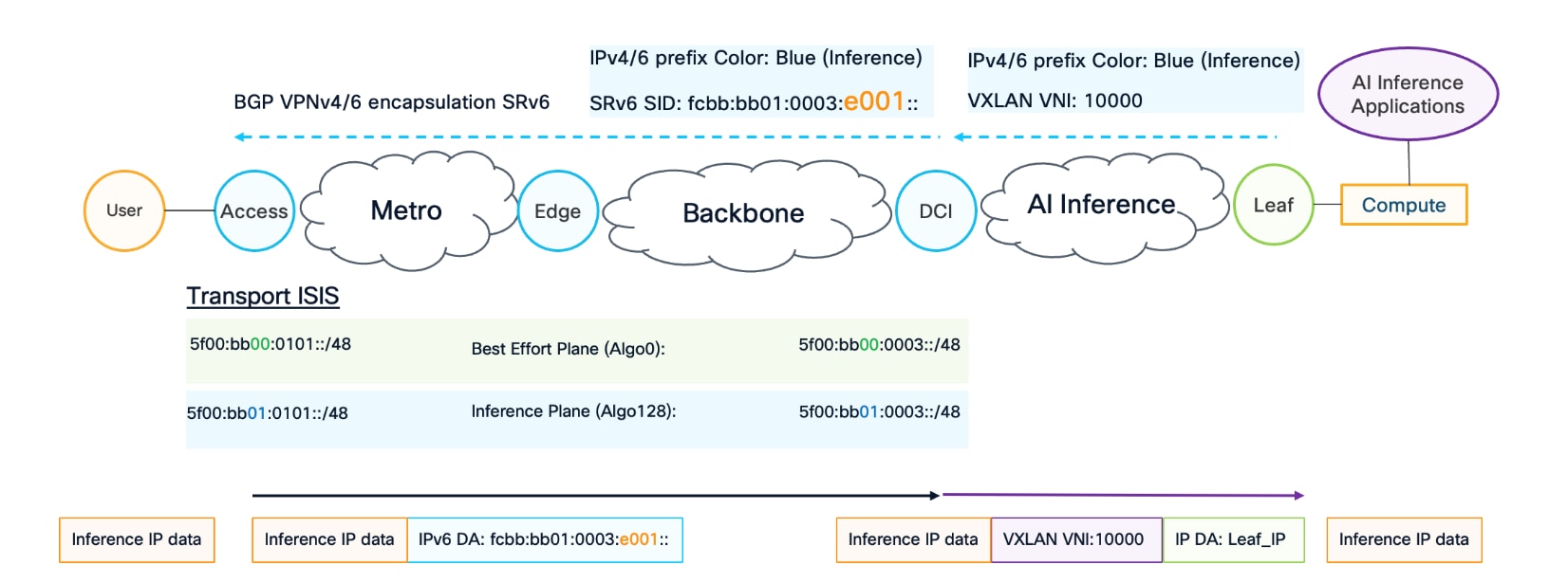
AI Inference cluster – AI Frontend service overlay
Figure 13 illustrates the remote connectivity model in which AI components are reached through an AI frontend that provides overlay services such as VXLAN. This model is typically associated with large, centralized deployments where multitenancy is required to support multiple tenants and service types, including AI inference.
In this model, the leaf advertises the IPv4 or IPv6 prefix associated with the AI inference service together with the required overlay information. In the example shown in Figure 12, the VXLAN overlay uses VNI 10000.
When supported, the leaf applies the appropriate BGP color directly to the advertised route. The color identifies the SLA and indicates the network plane that must be used to reach the prefix.
If the leaf does not support route coloring, it can tag the route using a standard BGP community. The DCI then translates the community into the appropriate color using a route policy.
SLA-based forwarding across multiple network planes is required primarily in the backbone and metro networks. The AI frontend generally does not require this type of forwarding because data center fabrics provide high-bandwidth links, extensive ECMP, a CLOS topology, and short paths between network devices and compute systems. These characteristics provide predictable and high-performance connectivity within the AI frontend.
The DCI uses the route color to signal the requested SLA and corresponding network plane toward the backbone and metro network. It provides both control-plane and data-plane stitching between the AI frontend and the backbone.
From a control-plane perspective, the DCI receives the route from the AI frontend and installs it in the appropriate routing context, such as a VRF or the global routing table. It then advertises the reachability toward the backbone or metro network as BGP VPNv4 or VPNv6, preserving the original color when available or applying the translated color when the route was tagged with a BGP community.
The DCI also advertises the associated SRv6 information required to transport traffic across the backbone according to the requested SLA.
The lower portion of Figure 13 illustrates the data-plane operation. An inference packet received from the user reaches the access device, which encapsulates the packet using SRv6 and steers it into the appropriate network plane, such as the inference plane.
When the packet arrives at the DCI, the SRv6 encapsulation is removed, and the inner IP header is used for a lookup in the appropriate VRF or routing table. The DCI then forwards the packet toward the AI frontend and encapsulates it using VXLAN with VNI 10000.
The leaf removes the VXLAN encapsulation and forwards the packet to the compute device. As described in the DCI section, VXLAN encapsulation and decapsulation may be performed on the leaf. The same forwarding model also applies when the VXLAN VTEP function is implemented directly on the compute device or smart NIC.
5.6.4. Remote connectivity - External peering
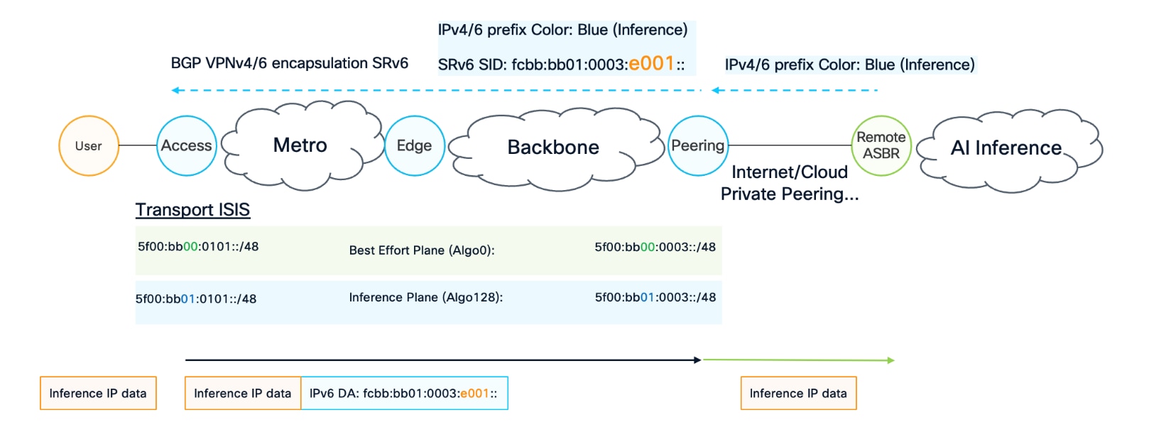
AI Inference cluster – External peering
Figure 14 illustrates the external peering model, in which the AI inference service is located behind an external peering connection. The external domain may be reached through Internet connectivity, cloud peering, or private peering.
In this model, the provider maintains control over the network up to the peering device but does not control the forwarding behavior within the external domain. Signaling between the local peering device and the remote Autonomous System Border Router (ASBR) is performed using BGP IPv4 or IPv6 address families.
The remote ASBR may signal the requested SLA directly by attaching the appropriate BGP color to the advertised prefix. Alternatively, the remote domain may use a standard BGP community. In that case, the peering device translates the community into the appropriate color before advertising the route toward the metro or backbone.
The peering device may also classify prefixes using a locally configured route policy or prefix list. This approach allows prefixes associated with AI inference services to be identified and assigned the appropriate color during advertisement toward the metro or backbone.
The resulting operation is similar to the direct IP handoff model. When the peering device receives a BGP IPv4 or IPv6 route update, it either preserves the existing color or translates the received community into the appropriate color. The peering device then advertises the route toward the backbone or metro using the corresponding BGP VPNv4 or VPNv6 route and the required SLA information.
The lower portion of Figure 13 illustrates the data-plane operation. The access device encapsulates the inference packet using SRv6 and steers it into the appropriate network plane, such as the inference plane. The packet is then transported across the metro and backbone networks toward the peering device.
At the peering device, the SRv6 encapsulation is removed, and the original IP packet containing the inference traffic is forwarded toward the remote ASBR and the external AI inference domain.
In the reverse direction, when bidirectional SLA signaling is supported, the peering node advertises its prefixes with the appropriate BGP color or community to the remote ASBR. The remote ASBR can then identify the requested SLA and apply the corresponding SLA-based forwarding within the external network. SLA treatment within the provider network remains limited to the portion of the path under the provider’s control.
5.6.5. Unified connectivity - AI Frontend unified with Backbone/Metro
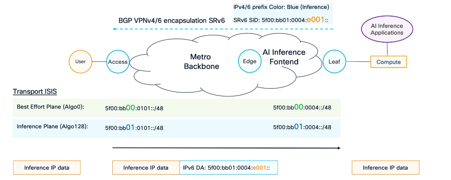
AI Inference cluster – External peering
Figure 15 illustrates the unified connectivity model, in which the AI inference frontend becomes part of the metro or backbone IGP domain. In this model, SRv6 encapsulation, decapsulation, and steering into the appropriate network plane based on the requested SLA are performed directly on the leaf device.
This model can be used in small or medium AI frontend deployments. At the edge, the leaf may be implemented using Cisco IOS XR and Cisco 8000 platforms. These platforms are often selected because the same infrastructure may support additional telco functions, including specific timing or form-factor requirements for telecommunications deployments.
The unified connectivity model is similar to the direct IP handoff model because the edge function is moved directly onto the leaf. When compute devices are connected to the leaf, the leaf advertises the associated IPv4 or IPv6 prefixes through BGP VPNv4 or VPNv6, together with the appropriate color identifying the required SLA.
The lower portion of Figure 15 illustrates the data-plane operation. The access device encapsulates traffic using the appropriate SRv6 SID and steers it into the network plane associated with the requested SLA. When the packet reaches the leaf, the SRv6 encapsulation is removed, and the packet is forwarded directly to the AI inference endpoint.
The primary difference between this model and the direct IP handoff model is that the AI frontend is integrated directly into the metro or backbone IGP domain. This approach is generally better suited to small and medium deployments because it does not provide the same routing-domain separation as a large deployment using a dedicated DCI.
For large AI frontend deployments, a separate DCI and clear separation between the AI frontend and backbone routing domains are typically required to provide the necessary scale, isolation, and operational flexibility.
5.6.6. Shared IP endpoint connectivity
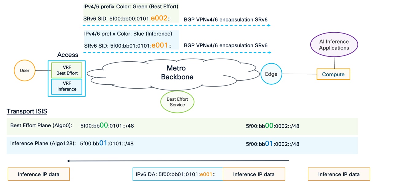
AI Inference cluster – Shared IP endpoint connectivity
Figure 16 illustrates the shared IP endpoint connectivity model, in which the same IP address or prefix must support multiple SLA types.
In the previous examples, each AI component or service was associated with a dedicated IP address or prefix. The prefix was advertised through BGP VPNv4 or VPNv6 with an appropriate color identifying the required SLA. Consequently, all traffic destined for that prefix followed the same network plane.
This approach is not sufficient when an end user or endpoint uses the same IP address for multiple services. For example, the same endpoint may access both general-purpose services and AI inference services, each with different SLA requirements. In this case, traffic must be steered into the appropriate network plane according to a local decision at the ingress forwarding point rather than relying on a single SLA signaled with the destination route.
As shown in Figure 16, the endpoint is connected to the access device through two different VRFs. Each VRF represents a separate network plane. The access device advertises the same user IP address or prefix from each VRF through BGP VPNv4 or VPNv6, assigning a different color to each advertisement.
The access device therefore provides remote network nodes with multiple forwarding options for the same destination. Each route advertisement includes the SRv6 information associated with its respective plane. Because each plane uses a separate address block, locator, and service function, the corresponding SRv6 SID is different for each advertisement.
The access device does not select a single SLA for all traffic destined for the endpoint. Instead, it advertises the available forwarding options, allowing the remote network device to select the appropriate route according to the service or network context from which the traffic originates.
At the remote edge device connected to the AI inference components, the inference VRF imports the user route based on the route target associated with the inference service. When an inference component sends traffic toward the user, the edge device encapsulates the packet using the SRv6 SID allocated by the access device for the inference plane and steers the traffic through that plane.
Similarly, a remote device hosting a best-effort service, such as a web service, imports the corresponding BGP VPNv4 or VPNv6 route based on the route target associated with the best-effort service context. Traffic from that service toward the user is encapsulated using the SRv6 SID allocated by the access device for the best-effort plane.
Together with the other connectivity models described earlier, this shared IP approach supports all required connectivity options, including shared endpoint addresses. It also enables bidirectional forwarding while preserving the SLA requirements of each service.
5.7. Layer3 Data Center Interconnect (DCI) and Border Leaf (BL) design
This section describes how the AI frontend fabric connects to the backbone network. This interconnection is a critical part of the overall design because it must satisfy the feature and scale requirements of both the AI frontend fabric and the backbone.
This document focuses exclusively on a Layer 3 interconnect model. From a scalability and operational perspective, Layer 2 extension is not provided beyond the AI frontend fabric.
5.7.1. L3 Data Center Interconnect – L3 DCI
There are two primary options for implementing the Layer 3 interconnect. The first option, shown in
Figure 17, uses a dedicated Data Center Interconnect (DCI) node. In this model, the DCI device terminates the encapsulation used by the AI frontend fabric, such as VXLAN or SRv6 uSID, performs a Layer 3 lookup, and then re-encapsulates the traffic for transport across the backbone.
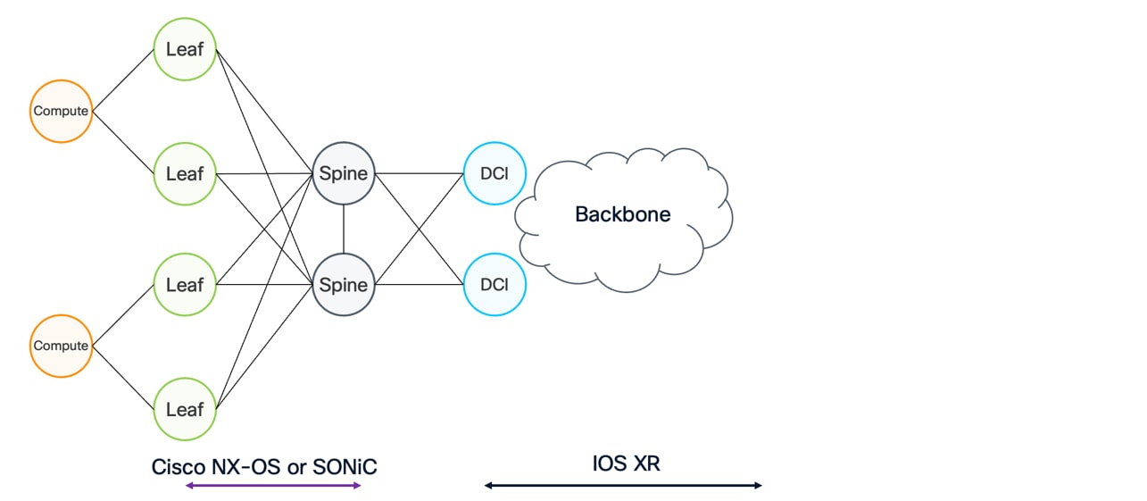
Backbone to Datacenter Interconnect
This approach provides a clean separation between the AI frontend fabric and the backbone, allowing each domain to use the data-plane technology best suited to its requirements.
In this design, a dedicated DCI node connects the AI frontend fabric to the backbone. The DCI node is based on Cisco Silicon One Network Processing Units (NPUs) and runs Cisco IOS XR, providing the advanced feature set required for backbone operation, including traffic engineering and fast reroute.
The AI frontend fabric remains unchanged. The Appendix section on EVPN host routing explains why host routes are required when a subnet is stretched across multiple leaf nodes. This section builds on that discussion by describing how those host routes must be summarized when IP reachability is advertised from the DCI nodes toward the backbone. This summarization is essential for removing host-route scale requirements from remote backbone nodes.
As shown in Figure 17, the AI frontend fabric is connected to two DCI nodes, DCI1 and DCI2. Beyond these nodes is an IP or MPLS backbone, with a remote node represented by DCI3. DCI1 and DCI2 terminate the VXLAN encapsulation originating from the leaf layer, perform an IP lookup in the appropriate routing context—either a VRF or the global routing table—and then re-encapsulate the traffic using the backbone data plane, such as SRv6 uSID.
This IP lookup at the DCI is critical for scalability. At the leaf layer, individual host routes are generated for each compute host to ensure correct forwarding within the EVPN fabric. Advertising all of these host routes into the backbone, however, would not scale. Instead, the DCI summarizes the host routes into aggregated prefixes, such as the subnet prefix X.X.X.0/24 shown in Figure 17 and advertises only the summarized reachability toward the backbone.
From the backbone’s perspective, the prefix X.X.X.0/24 is reachable through DCI1 and DCI2. Packets arriving from the backbone are therefore encapsulated using SRv6 and load-balanced across DCI1 and DCI2 using ECMP. When a packet arrives at either DCI node, it is decapsulated and subjected to a local IP lookup.
At this point, DCI1 and DCI2 must retain the complete set of host routes in their local forwarding tables. These host routes allow the DCI nodes to determine the correct destination leaf or leaves. For example, traffic destined for Compute 1 at IP address X.X.X.10 is forwarded toward LEAF1 and LEAF2, while traffic destined for Compute 2 at IP address X.X.X.20 is forwarded toward LEAF3 and LEAF4.
If the DCI nodes did not retain this host-route information, they would be unable to forward traffic correctly after decapsulation, and packets could be sent to the wrong destination. The DCI layer therefore serves two roles: it interconnects the different data planes used by the AI frontend fabric and the backbone, and it provides the summarization boundary where detailed host routes are retained while only aggregated reachability is advertised to the backbone.
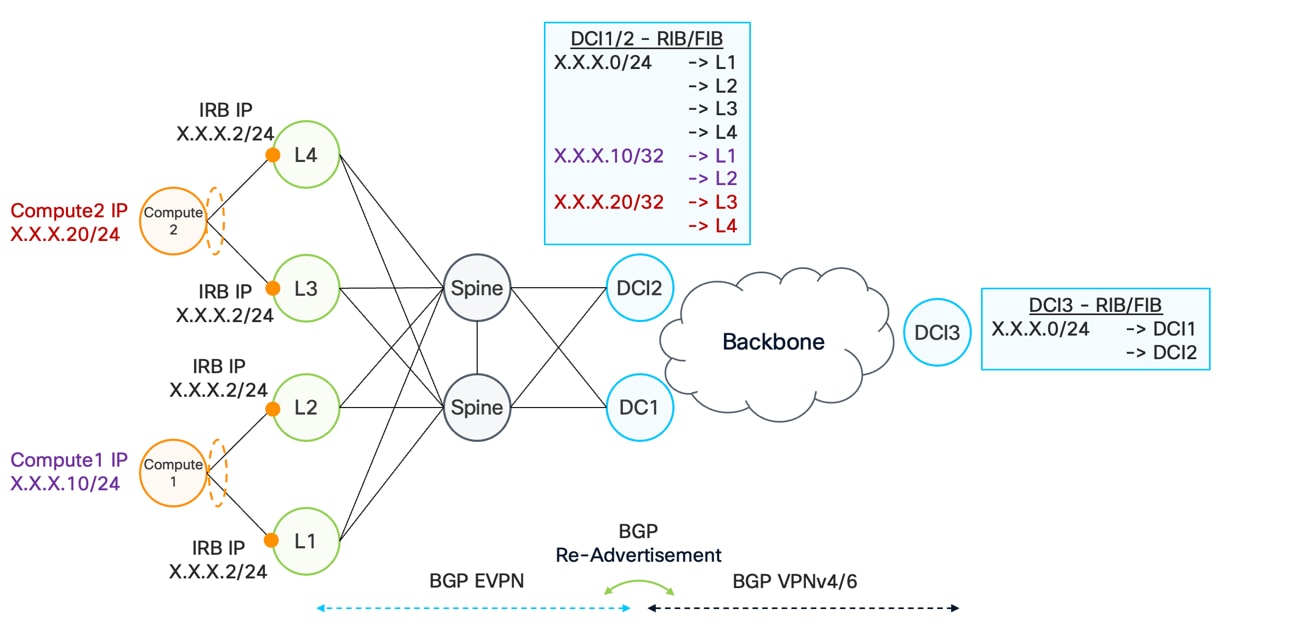
DCI Route Summarization
The same principle applies when a subnet is not stretched across multiple leaves. In the previous example, the subnet X.X.X.0/24 was available across all four leaves. In another scenario, separate subnets may be used—for example, one subnet assigned to LEAF1 and LEAF2 and another subnet assigned to LEAF3 and LEAF4.
In this case, the DCI can summarize the two subnets into a single aggregated prefix before advertising reachability toward the backbone. This approach improves scalability by reducing the number of routes carried in the backbone. Although it is technically possible to advertise both individual subnets, or even individual host routes, doing so may create unnecessary control-plane and data-plane scale requirements.
Summarization at the DCI boundary is therefore a best practice. It limits the propagation of routing information, improves scalability, and preserves correct forwarding behavior within the AI frontend fabric.
Another important consideration is the number of next hops that must be supported. In current AI frontend designs, VXLAN termination and VTEP functionality may be implemented directly on compute smart NIC. This increases the number of next hops visible from the DCI. Each next hop consumes data-plane resources associated with encapsulation and forwarding.
From a BGP control-plane perspective, the architecture within the AI frontend fabric remains unchanged. The AI frontend continues to use BGP EVPN to advertise reachability and overlay information. Within the backbone, routing is typically handled using BGP VPNv4 or VPNv6.
The DCI performs the interworking between these two BGP overlay domains. When the DCI receives a BGP EVPN Route Type 5 advertisement from the AI frontend fabric, it translates and re-advertises the corresponding reachability into the backbone as a BGP VPNv4 or VPNv6 route. Conversely, routes learned from the backbone through VPNv4 or VPNv6 can be re-advertised into the AI frontend fabric as EVPN Route Type 5 routes.
5.7.2. Border Leaf – BL/DCI-Lite
The second option for interconnecting the AI frontend fabric with the backbone is the Border Leaf (BL), also referred to as a DCI Lite solution. In this approach, the DCI function is divided between two devices, as illustrated in Figure 18.
The border leaf terminates the VXLAN encapsulation from the AI frontend fabric. After terminating the VXLAN traffic, the border leaf performs a Layer 3 lookup and provides a pure IP handoff to a second device.
This second device is typically an Autonomous System Border Router (ASBR), also referred to as a Provider Edge (PE) router, which connects directly to the backbone. The ASBR handles backbone-facing functions, including MPLS or SRv6 encapsulation and the advanced transport features required within the backbone. By dividing the DCI function between two devices, this architecture allows each device to focus on the requirements of its respective domain.
A key advantage of this design is platform flexibility. The border leaf can be implemented using Cisco NX-OS or SONiC-based device optimized for the AI frontend fabric, while the ASBR can use an IOS XR-based platform to support the full feature set required for backbone connectivity.
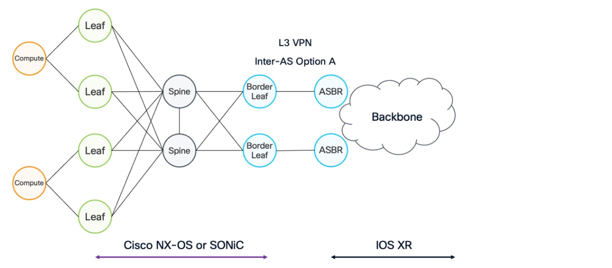
Border Leaf – DCI Lite
5.8. DCI Layer3 control plane with EVPN
EVPN Route Type 5 is used for IP prefix advertisement and provides Layer 3 reachability information within the EVPN framework. Functionally, EVPN Route Type 5 serves a role similar to traditional BGP VPNv4 and VPNv6 address families, which are commonly used in MPLS or SRv6 based networks to distribute L3VPN routes.
In VXLAN based EVPN deployments, there is no direct equivalent to the VPNv4 or VPNv6 BGP address families. Instead, BGP EVPN Route Type 5 is the mechanism used to advertise IP prefixes and enable L3VPN services.
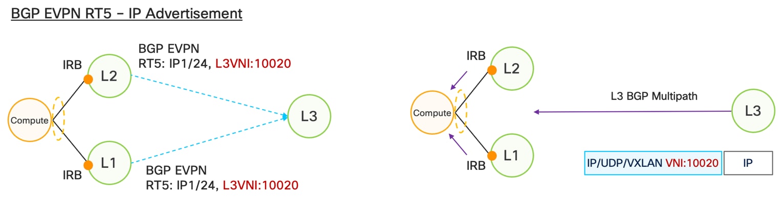
IP Advertisement with EVPN RT5
Figure 20 illustrates how LEAF1 and LEAF2 advertise an BGP EVPN Route Type 5 for the same IP prefix, IP1/24, with the appropriate VXLAN L3VNI, VNI 10020. While this example focuses on IPv4, the behavior is identical for IPv6 prefixes.
On the right side of Figure 20, the corresponding data plane behavior is shown. When both LEAF1 and LEAF2 advertise the same prefix, the remote node, LEAF3, installs multiple next hops for that prefix using BGP multipath. As a result, LEAF3 encapsulates traffic destined for IP1/24 using VXLAN, adding the outer IP and UDP headers followed by the VXLAN header carrying VNI 10020. Traffic is then load balanced on a per flow basis across LEAF1 and LEAF2.
The advertised prefix, IP1/24 in this example, may be locally connected, statically configured on the leaf, or it may be learned dynamically through other routing protocols, such as BGP from the compute. More advanced use cases and additional details on how EVPN Route Type 5 is used to advertise these prefixes will be discussed later in this document.
5.9. EVPN Layer3 distributed anycast gateway
EVPN distributed anycast gateway is another important component for supporting EVPN multi homing. As shown in Figure 20, LEAF1 and LEAF2 both multi home the same Ethernet segment, ESI1 and use Integrated Routing and Bridging (IRB) to provide IP connectivity to the compute node. From the compute perspective, this connectivity remains fully transparent at Layer 2, as discussed in earlier sections.
In addition to Layer 2 transparency, LEAF1 and LEAF2 must also present a consistent and transparent Layer 3 view. To achieve this, the IRB interfaces on both leaves are configured with the same IP address and the same MAC address, effectively creating an anycast gateway. This allows the compute node to use a single default gateway regardless of which leaf it is forwarding traffic through.
Just as MAC address synchronization was required between LEAF1 and LEAF2 in the Layer 2 multi homing case, Layer 3 state must also be synchronized. This includes adjacency information, such as ARP entries for IPv4 and Neighbor Discovery entries for IPv6.
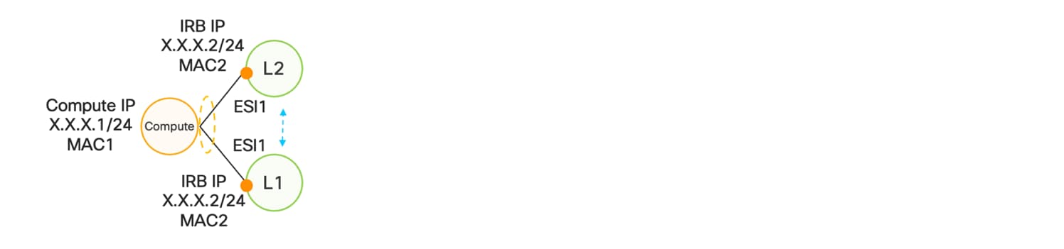
Distributed Anycast Gateway
5.10. EVPN Route Type 2 (RT2) – MAC+IP
Figure 22 illustrates the synchronization of adjacency information between LEAF1 and LEAF2, as well as the advertisement of host reachability to a remote leaf, LEAF3. In earlier sections, the concept of a distributed anycast gateway implemented through IRB was introduced, along with the requirement to synchronize adjacency information between multi homed leaves. This section explains how the BGP EVPN control plane is used to perform that synchronization.
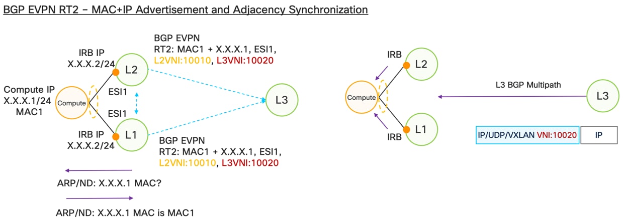
Mac and IP Advertisement
Similar to the Layer 2 use case, the Layer 3 scenario also relies on BGP EVPN Route Type 2. In this context, EVPN Route Type 2 carries not only the Ethernet Segment Identifier (ESI1 in this example) and the MAC address (MAC1), but also the associated IP address (X.X.X.1). This additional information allows the creation of complete adjacency entries, including ARP entries for IPv4 and Neighbor Discovery entries for IPv6.
Adjacency information must first be learned locally. In this example, LEAF1 sends an ARP request to the compute node to resolve the MAC address associated with IP X.X.X.1 address. The compute node responds with an ARP reply indicating that IP X.X.X.1 is reachable via MAC1. An equivalent process occurs for IPv6 using the Neighbor Discovery protocol, which binds IPv6 addresses to MAC addresses. Once either LEAF1 or LEAF2 learns the adjacency information, it generates a BGP EVPN Route Type 2 that includes the MAC address (MAC1), the IP address (X.X.X.1), the Ethernet segment from which the information was learned (ESI1), and the relevant VXLAN VNIs. In this example, the L2VNI is 10010 and the L3VNI is 10020.
This EVPN Route Type 2 is then advertised across the EVPN fabric and received by both LEAF2 and LEAF3. From the perspective of LEAF3, the route provides both Layer 2 and Layer 3 forwarding information, effectively advertising a host route that can be used for Layer 3 unicast forwarding. At the same time, as with MAC only EVPN Route Type 2 advertisements, this route is also used between LEAF1 and LEAF2 for synchronization purposes.
Through this exchange, LEAF1 and LEAF2 install identical adjacency entries pointing toward their locally connected bundle interface associated with ESI1. As a result, both leaves maintain a fully synchronized view of Layer 3 adjacency information, ensuring consistent forwarding behavior and seamless operation of the distributed anycast gateway.
In the previous section, we introduced the EVPN distributed anycast gateway and highlighted the importance of host routing within an EVPN fabric. It was shown how BGP EVPN Route Type 2 carrying both MAC and IP information is used to synchronize adjacency state between two leaf nodes that are multi homing the same device—in this example, LEAF1 and LEAF2 connecting to the same compute node. At the same time, this EVPN Route Type 2 is also advertised to remote leaves, effectively distributing host specific routing information across the fabric.
This naturally raises the question of why host routing is required in an EVPN fabric that uses a distributed anycast gateway. Figure 17 illustrates a more complex topology that helps clarify this requirement. On the left side of the topology, LEAF1 and LEAF2 multi home Compute 1, while LEAF3 and LEAF4 multi home Compute 2. All four leaves participate in a distributed anycast gateway implemented by using IRB, and all are configured with the same subnet, for example X.X.X.0/24. In this example, Compute 1 uses IP address X.X.X.10/24 and Compute 2 uses IP address X.X.X.20/24.
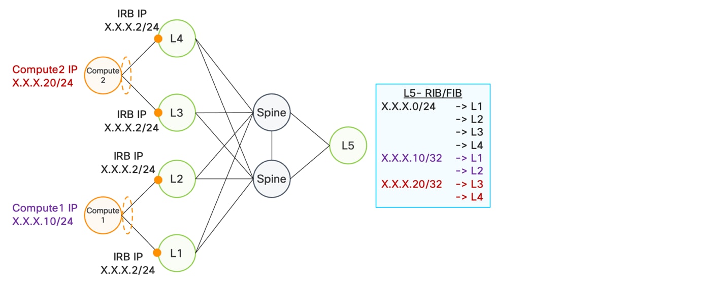
EVPN Host Routing
Considering the forwarding behavior from the perspective of a remote leaf, such as LEAF5, in a traditional L3VPN design, only the subnet prefix X.X.X.0/24 would be advertised, using BGP EVPN Route Type 5. In this case, that prefix is advertised by all four leaves as a connected subnet via their IRB interfaces. As a result, LEAF5 sees Equal Cost Paths (ECMP) for the prefix X.X.X.0/24 via LEAF1, LEAF2, LEAF3, and LEAF4.
If host routes were not present, traffic destined for Compute 1 (IP X.X.X.10) would be forwarded based solely on the subnet route. LEAF5 could select any of the four leaves as the next hop, including LEAF3 or LEAF4, which do not have connectivity to Compute 1. This would clearly result in incorrect forwarding.
To avoid this issue, EVPN introduces host routing. Each compute node is advertised using a host specific route, learned and distributed via BGP EVPN Route Type 2. These host routes provide precise reachability information, ensuring that traffic destined for IP X.X.X.10 is forwarded only toward LEAF1 and LEAF2, while traffic destined for IP X.X.X.20 is forwarded only toward LEAF3 and LEAF4.
Because host routes are more specific than the subnet route, they take precedence in the forwarding decision. This allows remote leaves to load balance traffic on a per flow basis across the correct pair of leaves that are multi homing the destination compute. In this way, host routing is a fundamental requirement when stretching subnets across an EVPN fabric with a distributed anycast gateway, ensuring both correct forwarding and efficient load balancing.
5.12. EVPN Route Type 5 (RT5) with IP Gateway
Figure 24 illustrates the details defined in RFC 9136, which specifies IP prefix advertisement in EVPN. The figure highlights the structure of the EVPN Route Type 5 and, in particular, emphasizes the IP gateway portion of the route.
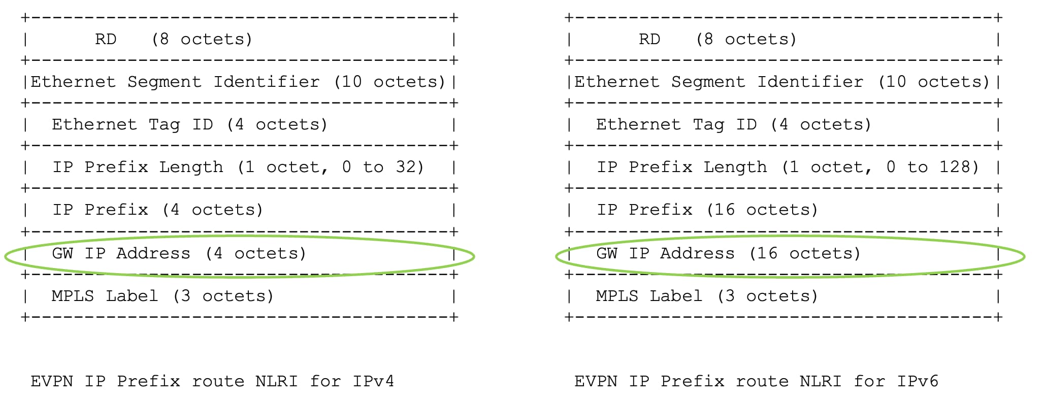
RT5 with IP Gateway
5.13. BGP EVPN RT5 with IP Gateway - Weighted ECMP
This section describes how EVPN Route Type 5, together with the IP Gateway field, can be used to implement weighted ECMP within the AI front end EVPN fabric. To understand why weighted ECMP is required, it is first important to examine the forwarding challenges that arise in large scale environments.
As illustrated in Figure 25, multiple compute nodes are connected to the EVPN fabric through different leaf nodes. In this example, the compute nodes are spread across two subnets, X.X.X.0/24 and Y.Y.Y.0/24. For simplicity, each compute hosts a single application instance and advertises the same anycast prefix, A.A.A.0/24.
In this topology, Compute 1 is connected to LEAF1, Compute 2 is connected to LEAF2, and Compute 3 and Compute 4 are both connected to LEAF3. All leaf nodes learn the anycast prefix A.A.A.0/24 and advertise it into the EVPN overlay as EVPN Route Type 5 with the appropriate VXLAN information.
From the perspective of a remote node, such as DCI1 or DCI2, the prefix A.A.A.0/24 is learned via multiple EVPN Route Type 5 advertisements. BGP multipath installs equal cost paths via LEAF1, LEAF2, and LEAF3. As a result, traffic destined for A.A.A.0/24 is load balanced equally across all three leaves.
This equal cost load balancing creates a mismatch between traffic distribution and compute capacity. LEAF3 connects two compute nodes, while LEAF1 and LEAF2 each connect only one compute node. Ideally, LEAF3 should receive a proportionally larger share of the traffic. This requirement motivates the need for weighted ECMP in the EVPN fabric.
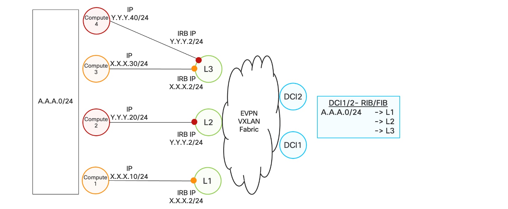
Weighted ECMP
The solution is illustrated in Figure 25, which builds on the IP Gateway mechanism introduced earlier. Instead of advertising a single next hop per leaf, the original next hops associated with each compute are preserved and advertised in the IP Gateway field of EVPN Route Type 5.
In this model, LEAF1 advertises A.A.A.0/24 with the IP Gateway field set to X.X.X.10, representing Compute 1. LEAF2 advertises the same prefix with the IP Gateway field set to Y.Y.Y.20, representing Compute 2. LEAF3 advertises the prefix via single BGP RT5 but with two IP Gateways, IP Gateway X.X.X.30 for Compute 3 and with IP Gateway Y.Y.Y.40 for Compute 4. These multiple IP Gateway entries are advertised using standard BGP Additional Paths (Add-Path) mechanism.
From a forwarding perspective, the prefix A.A.A.0/24 now resolves to four distinct next hops: X.X.X.10, Y.Y.Y.20, X.X.X.30, and Y.Y.Y.40. Each of these next hops represents a compute instance advertising the anycast prefix. A recursive lookup then resolves each compute IP address to the corresponding leaf node. In this example, X.X.X.10 resolves to LEAF1, Y.Y.Y.20 resolves to LEAF2, and both XXX.30 and YYY.40 resolve to LEAF3.
As a result, traffic destined for A.A.A.0/24 is naturally distributed across the leaves in proportion to the number of compute instances behind each leaf. LEAF3 receives twice the traffic flows of LEAF1 or LEAF2, achieving weighted ECMP without introducing any new BGP signaling constructs or explicit weight attributes.
By leveraging EVPN Route Type 5 with the IP Gateway field and standard recursive forwarding behavior, the EVPN fabric can implement effective weighted ECMP. This approach aligns traffic distribution with compute capacity while maintaining a clean separation between the control plane and the data plane and preserving optimal forwarding behavior within the AI front end network.
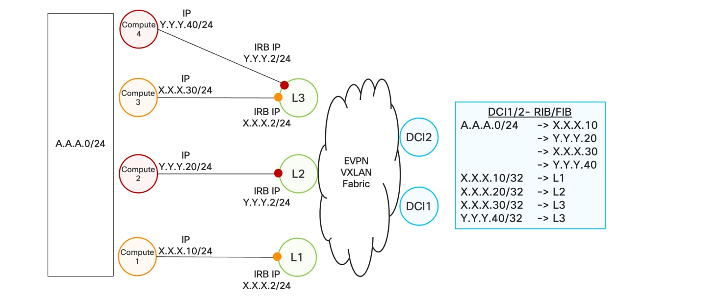
IP Gateway
AI inference introduces a new security requirement for provider networks. The network is no longer only transporting generic enterprise and consumer traffic; it is carrying prompts, responses, embeddings, retrieval context, operational telemetry, customer records, and potentially regulated or proprietary business data. In many cases, this traffic is exchanged in real time between enterprise users, consumers, AI gateways, inference clusters, model endpoints, security engines, and observability platforms. As a result, the inference path itself becomes part of the AI security architecture.
The network is becoming a critical communication fabric that enables digital workers—AI agents—to connect with their respective models and perform inference. As a result, the network itself becomes a valuable and mission-critical asset that must be protected against attacks.
A secure AI Inference Cloud therefore requires transport network security at four complementary layers:
● an encrypted network path protecting inference traffic and network itself
● trusted infrastructure platforms assuring trust and integrity of underlay network
● a DDoS implementation protecting inference endpoints from attacks
● a secure network OS and software stack assuring against vulnerabilities
Together, these capabilities allow the provider to protect the confidentiality, integrity, isolation, and operational reliability of AI traffic across distributed infrastructure.
6.1.1. Encrypted network path for AI Inference
The first requirement is to secure the network path used by AI inference traffic. Inference requests and responses may contain sensitive content, including personally identifiable information, financial records, healthcare data, enterprise documents, source code, customer interactions, or operational network data. Even when model execution occurs in a trusted location, the traffic path between the customer and the inference endpoint must also be protected.
AI inference services commonly protect client-to-model traffic with TLS, usually through HTTPS. With HTTP/1.1 or HTTP/2, TLS runs over TCP, which provides reliable delivery while TLS provides encryption and authentication. This protects prompts, responses, and API credentials as they travel across the network. Some inference services use HTTP/3, which runs over QUIC instead of TCP. QUIC integrates TLS 1.3 into its connection, encrypting application data in transit. Both TCP with TLS and QUIC help prevent network observers from reading or altering inference payloads. Encryption still leaves some information visible, including IP addresses, traffic timing, packet sizes, and connection metadata. TLS also does not guarantee that every proxy or service along the route preserves end-to-end protection. Inference deployments should choose supported secure transports where appropriate.
An encrypted AI inference network path ensures that traffic remains confidential as it traverses the provider network, metro infrastructure, regional data centers, edge locations, and cloud interconnects over peerings. This can be implemented using transport encryption technologies such as IPsec, MACsec, or encrypted overlays, depending on the service model and network domain. The goal is to provide confidentiality and integrity from the enterprise access point to the AI gateway, and from the gateway to the inference execution environment.
AI inference traffic carries sensitive prompts, proprietary model data, and regulated information with a confidentiality lifetime of many years, its exposure window extends therefore harvest now, decrypt later" attacks becomes a key point for security framework. Post Quantum security framework ensures network path is secured against those.
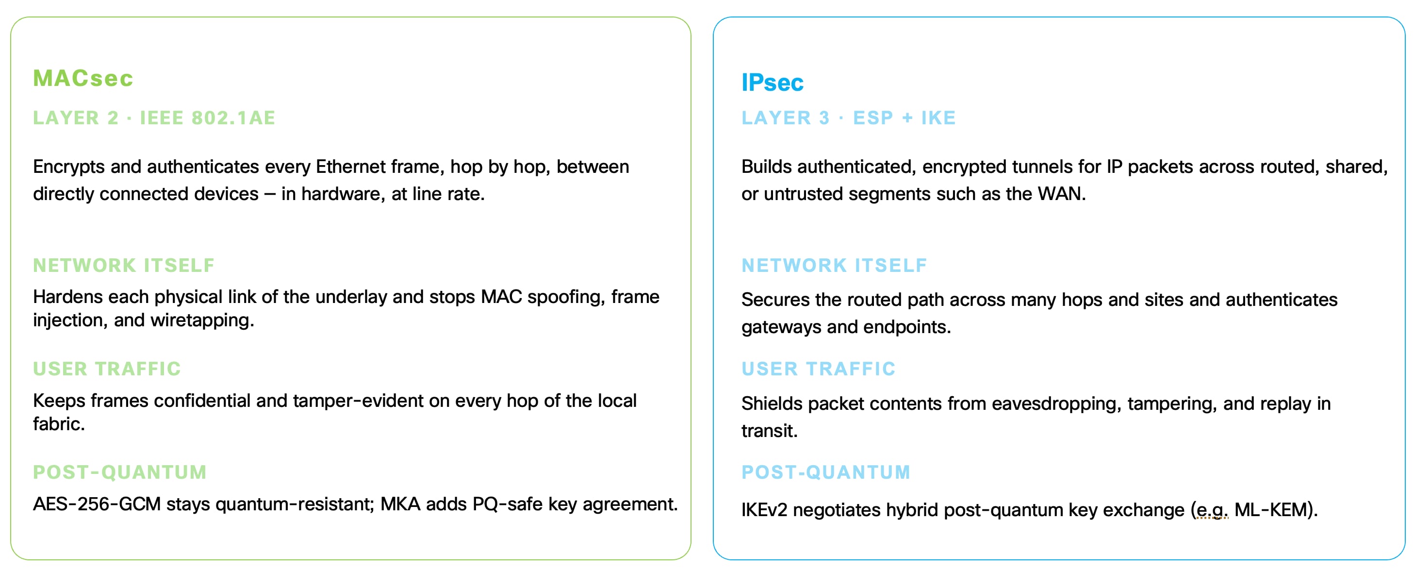
Securing Transport Layer
6.1.2. Platform security with trust anchor module chips
A secure inference network also depends on the trustworthiness of the infrastructure platforms that forward, host, and secure the traffic. Routers, switches, edge nodes, AI gateways, and compute platforms become part of the trusted execution chain. If one of these platforms is compromised, the confidentiality and integrity of the inference service can be undermined even if the traffic itself is encrypted.
Platform security begins with hardware-based trust. Cisco platforms use hardware trust mechanisms such as Trust Anchor Module capabilities to establish a secure root of trust. A hardware root of trust provides a foundation for verifying that the device boots with authentic software, that firmware has not been tampered with, and that the platform identity can be cryptographically validated.
This matters in an AI Inference Cloud because the infrastructure is distributed. AI inference nodes may be deployed in central offices, metro facilities, regional data centers, edge locations, and customer-adjacent sites. These environments may not all have the same physical security posture as a centralized hyperscale facility. Hardware-based platform trust helps ensure that each node participating in the inference fabric can be authenticated and validated before it is allowed to carry or process sensitive AI traffic.
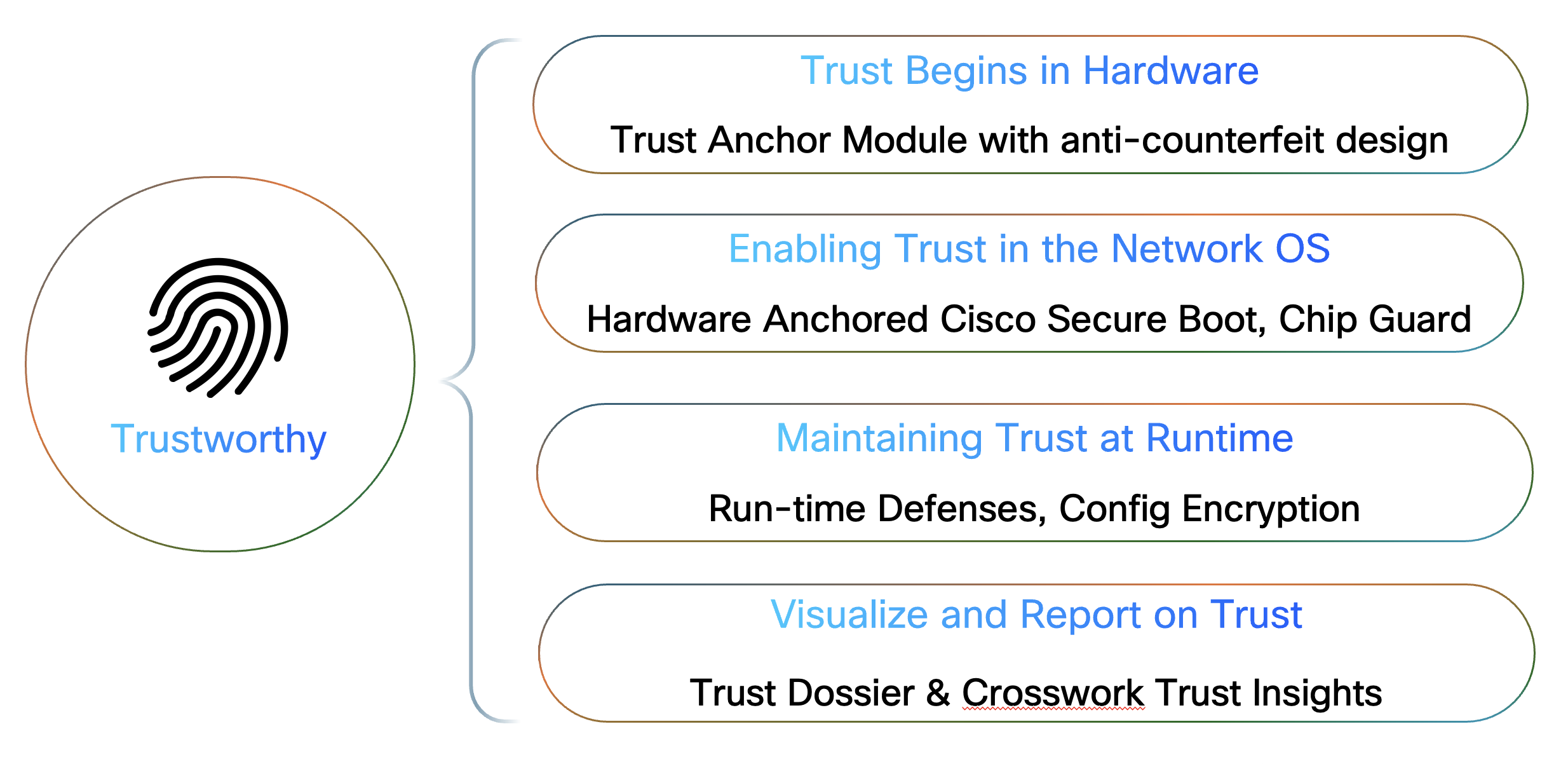
Trusted Platform Framework
6.1.3. DDoS protection for AI Inference endpoints
AI inference changes the DDoS problem from a generic network-availability issue into a direct threat against the AI service experience. Inference endpoints are not simple web servers; they sit in front of API gateways, LLM routers, security engines, model-serving platforms, GPU clusters, vector databases, and observability systems. A successful DDoS attack can therefore affect not only bandwidth, but also inference queue depth, GPU utilization, model response time, time-to-first-token, inter-token latency, and service availability.
For AI inference, DDoS protection must address two directions of risk.
● The first is server-side protection, where attackers attempt to overwhelm public or private AI inference endpoints, AI gateways, API gateways, or hosted enterprise model services.
● The second is client-side protection, where compromised subscribers, enterprise endpoints, IoT devices, or consumer devices generate attack traffic toward an AI inference service or use the provider network as an attack source.
In both cases, the provider must protect the availability of the inference path before malicious traffic consumes backbone capacity, overloads service gateways, or reaches expensive GPU-backed infrastructure.
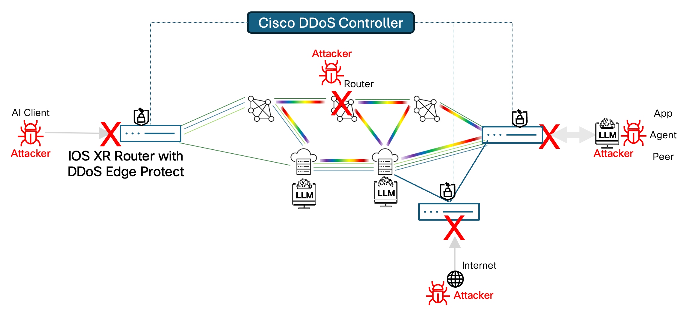
DDoS Protection for Inference
Cisco Secure DDoS Edge Protection help by identifying attack patterns before they reach these AI endpoints. The mitigation point is moved closer to the network ingress, so malicious traffic can be blocked before it consumes backbone bandwidth, overwhelms load balancers, or reaches the inference gateway. This protects not only the application endpoint, but also the expensive and scarce compute resources behind it.
In an AI Inference architecture, this should be positioned as availability protection for the AI service perimeter. It complements, rather than replaces, AI-specific security functions. Providers need to detect and suppress attack traffic close to the originating point therefore DDoS placement has to be as close as to and Inference endpoint.
6.1.4. Datapath Software vulnerability protection
AI Inference Cloud introduces a new class of infrastructure risk. The routers, switches, edge nodes, and service platforms that carry inference traffic are no longer only transport elements; they become part of the trusted execution path for AI services. These platforms connect enterprise users, AI gateways, inference routers, model-serving clusters, GPU infrastructure, observability systems, security engines, and cloud or edge inference endpoints. If a vulnerability exists in this infrastructure layer, it can directly affect the availability, integrity, and trustworthiness of the AI inference service.
This creates a critical operational challenge for providers. AI inference services are expected to be always available, low latency, secure, and SLA-driven. At the same time, the infrastructure that supports those services must be continuously protected against newly discovered vulnerabilities. Traditional software patching and image upgrades remain essential, but they often require testing, qualification, change approval, maintenance windows, and in some cases disruptive reloads or service-impacting upgrades. For a distributed inference platform, this creates a dangerous gap between the moment a vulnerability becomes known and the moment a permanent software fix can be safely deployed across the network.
For this reason, AI Inference Architecture requires a runtime infrastructure protection model in addition to conventional patch management. The objective is not to replace permanent software fixes. The objective is to reduce exposure during the vulnerable window between discovery and full remediation. Runtime protection provides an interim shield that allows providers to protect critical infrastructure quickly, maintain service continuity, and complete permanent remediation through controlled operational processes.
Cisco Live Protect closes this gap by enabling validated protective controls to be applied directly to the running infrastructure. These protections reduce the exploitability of known vulnerabilities without requiring the operator to immediately perform a full software upgrade or service-disrupting maintenance action. This gives the provider a faster response option during the most critical period of exposure.
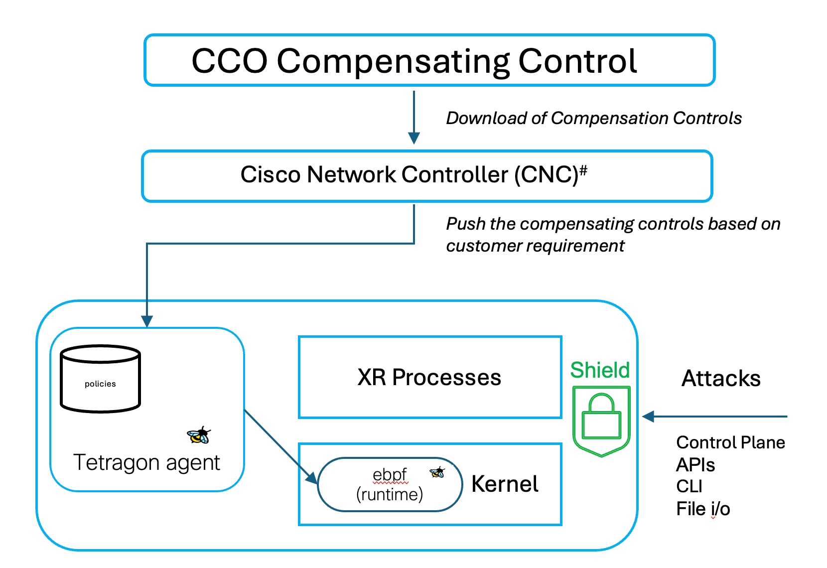
Cisco Live Protect
For AI inference, this capability addresses several important risks and protects service continuity, protects the trusted infrastructure path and supports operationally controlled security response.
7. Automation, observability and assurance
7.1. Why inference automation is needed
AI inference is a dynamic, distributed service. Inference endpoints may be located at far-edge sites, metro data centers, regional AI facilities, or external cloud and neocloud platforms. Demand changes continuously across users, enterprises, models, and locations, while failures, congestion, and model capacity changes can affect the best path to an inference endpoint. Manual network configuration cannot respond quickly or consistently enough to maintain the required application performance.
Automation is therefore needed to translate service intent into network behavior. Application and service requirements—such as latency, bandwidth, availability, isolation, security, and data sovereignty—must be converted into policies that the network can enforce and continuously adapt. This includes selecting the appropriate VPN, transport slice, Segment Routing over IPv6 (SRv6) policy, Flex-Algo topology, Quality of Service (QoS) treatment, security controls, and monitoring profile.
Automation supports three operational priorities:
Table 6. Automation priorities
| Priority |
Core capabilities |
Outcome |
| Deliver premium services quickly |
On-demand provisioning; reusable service templates; SLA-aware paths, slices, and monitoring; API integration with OSS/BSS and infrastructure as code |
Shorter order-to-service time and consistent implementation of differentiated service tiers |
| Operate efficiently at scale |
Topology and traffic visibility; service alarms; zero-touch provisioning; fleet upgrades; configuration audits; controlled maintenance workflows with pre- and post-checks |
Lower operational effort and configuration risk across large, multivendor networks |
| Minimize disruption and recovery time |
Resilient transport; continuous path optimization; KPI-triggered remediation; policy-controlled re-steering and recovery validation |
Faster mitigation of failures, congestion, and SLO degradation |
Automation becomes most valuable when it operates as a closed loop. The system continuously collects network and inference telemetry, correlates the results, and compares actual performance with the intended service objectives. Network indicators may include latency, jitter, packet loss, bandwidth, path health, and availability. AI-specific indicators may include time to first token, inter-token latency, queueing delay, completion rate, and inference flow loss.AI agents can further assist operations through reactive root-cause analysis, preventive detection of emerging failures, and prescriptive recommendations for configuration improvements.
AI agents can further assist the operations team by identifying likely root causes, detecting emerging failures, and recommending preventive or corrective actions. These recommendations can be evaluated against operator policies before being applied through the automation system.
7.2. Why inference assurance is needed
Customers purchase a measurable inference experience—not merely endpoint reachability or a successful HTTP response. An HTTP success code confirms only that a request was accepted or returned; it does not demonstrate that the service met its objectives for responsiveness, streaming quality, completion, endpoint placement, security, or data sovereignty.
The customer experience depends on an end-to-end delivery chain that spans the application, access network, WAN, peering or Data Center Interconnect (DCI), AI gateway, and model-serving platform. Inference assurance provides visibility across this complete chain, linking customer-visible outcomes to the infrastructure that transports and processes each request. This enables the provider to identify affected services and customers, verify compliance with Service-Level Objectives (SLOs), isolate the domains contributing to degradation, and confirm that corrective actions have restored the expected experience.
Inference assurance combines three evidence layers:
Table 7. Inference layers
| Evidence layer |
What it measures |
Operational purpose |
| Inference experience |
Response start, inference quality, completion, and errors from users or synthetic transactions |
Establish whether the service met its objectives |
| Delivery path |
Delay, jitter, loss, utilization, congestion, routing, class of service, and ECMP path |
Identify network conditions contributing to degradation |
| Serving system |
Gateway selection, admission, queues, model execution, cache behavior, Kubernetes state, and accelerator health |
Explain processing conditions when the provider operates the platform or receives its telemetry |
Together, these capabilities transform a vague complaint that “the AI service is slow” into a precisely scoped incident tied to the affected customer, workload, location, service tier, inference endpoint, network path, and time window.
7.3. Crosswork network controller as AI inference transport automation layer
In the AI Inference architecture, Crosswork Network Controller is the transport automation and service lifecycle controller. Its role is to automate the lifecycle of the network services that connect enterprise users, consumers, AI gateways, inference clusters, edge nodes, regional AI PODs, and public or private cloud inference endpoints.
At the service layer, Crosswork Network Controller supports provisioning and lifecycle management for transport slices, and related transport constructs. These capabilities are important because AI inference services may be delivered in different forms. Some customers may consume inference through private L3VPN connectivity. Others may require L2 point-to-point access into a dedicated inference platform. Some may use a transport slice with a low-latency or sovereign intent. Others may require SRv6-based service steering across metro, regional, and core domains.
At the control layer, Crosswork integrates with SR-PCE and the Crosswork Optimization Engine to compute transport slices based on topology, latency, bandwidth, disjointness, affinities, and other constraints. This is a direct influence to AI inference because the optimal path to an inference endpoint may depend on service tier, location, current network conditions, and policy constraints. A premium inference customer can be mapped to a low-latency SR policy. A sovereign workload can be mapped to a constrained transport plane. A mission-critical AI service can be mapped to disjoint primary and backup paths.
At the provisioning layer, Crosswork uses NSO as the service provisioning engine. This allows high-level service intent to be translated into device configuration through model-driven service packages and device abstractions. In an AI Inference Cloud, this is valuable because providers can expose AI transport services through APIs or user interfaces while maintaining consistent, validated configuration across the network.
At the data collection layer, Crosswork Data Gateway provides scalable data collection from network devices using protocols such as SNMP, gNMI, model-driven telemetry, CLI, syslog, traps, and NETCONF. This data is used by Crosswork applications for topology, performance monitoring, service health, optimization, and external integrations. For AI inference, this telemetry foundation is critical because closed-loop automation depends on accurate and timely visibility into utilization, delay, faults, and service state.
The resulting architecture provides the key automation loop required for AI Inference Cloud: Provision → compute path → activate service → monitor service health → detect degradation → optimize or remediate → validate conformance. This is the operational foundation for delivering AI inference as a carrier-grade service rather than as static connectivity.
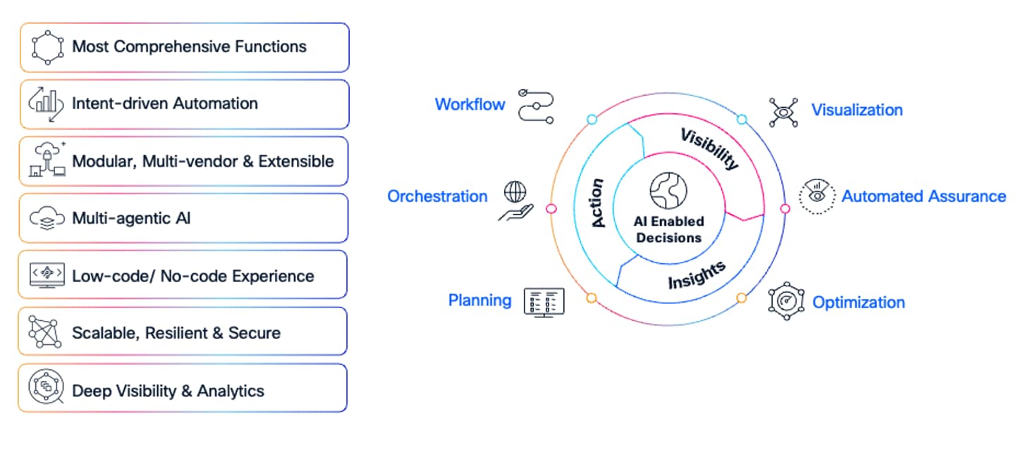
Automation and Assurance Loop for AI Inference
7.3.1. Inferencing service management and automation
This section complements the designs described in Section 4 by explaining how the Crosswork Network Controller (CNC) can automate the lifecycle of AI inference connectivity services. Using model-based provisioning and northbound APIs, providers can Create, Read, Update, and Delete (CRUD) services consistently across the network.
AI inference services should be provisioned according to service intent rather than through manual, device-level configuration. An Operations Support Systems/Business Support Systems (OSS/BSS) platform should be able to request an outcome such as:
● All traffic for a specific AI inference service must use a low-latency path between enterprise sites and a regional inference gateway.
● Traffic for a regulated AI workload must remain within defined national transport boundaries.
● The inference service must use physically or logically disjoint primary and backup paths.
● The customer requires an AI network slice with bandwidth assurance and proactive Service-Level Objective (SLO) monitoring.
CNC translates these requirements into the network services and policies needed to deliver them. The resulting AI transport service may include an L3VPN or EVPN, an underlay path based on Flex-Algo or SRv6 Traffic Engineering/On-Demand Next Hop (SRv6 TE/ODN/AS), edge Quality of Service (QoS), route-policy associations, security controls, and an assurance profile. The required performance-monitoring sessions can be activated as part of the same workflow, ensuring that service performance is measured from the time the service is deployed.
CNC supports both granular and composite provisioning models. In the granular model, operators can provision the individual components of the service and control the sequence in which they are applied. In the composite model, a service designer creates reusable catalog entries that combine the required connectivity, transport, security, and monitoring policies. For example, a secure-national-slice service could automatically create an L3VPN, bind it to a Flex-Algo that is restricted to sovereign transport links, apply MACsec protection, and activate the required assurance sessions.
A step-by-step workflow can also be used when the service requires more detailed control. CNC can first provision the VPN and then associate the relevant route policies, inference-specific VRF, Flex-Algo topology, and QoS treatment. Route policies that add BGP Color communities can be created through CNC and attached to the L3VPN as import or export policies. Where a customer requires an SRv6 TE policy to reach specific inference destinations, CNC can provision both the BGP Color-based route policies and the corresponding ODN templates. Custom-template functionality can extend the standard VPN provisioning models when additional configuration is required, such as assigning customer-originated inference traffic to a dedicated VRF with a distinct SLA.
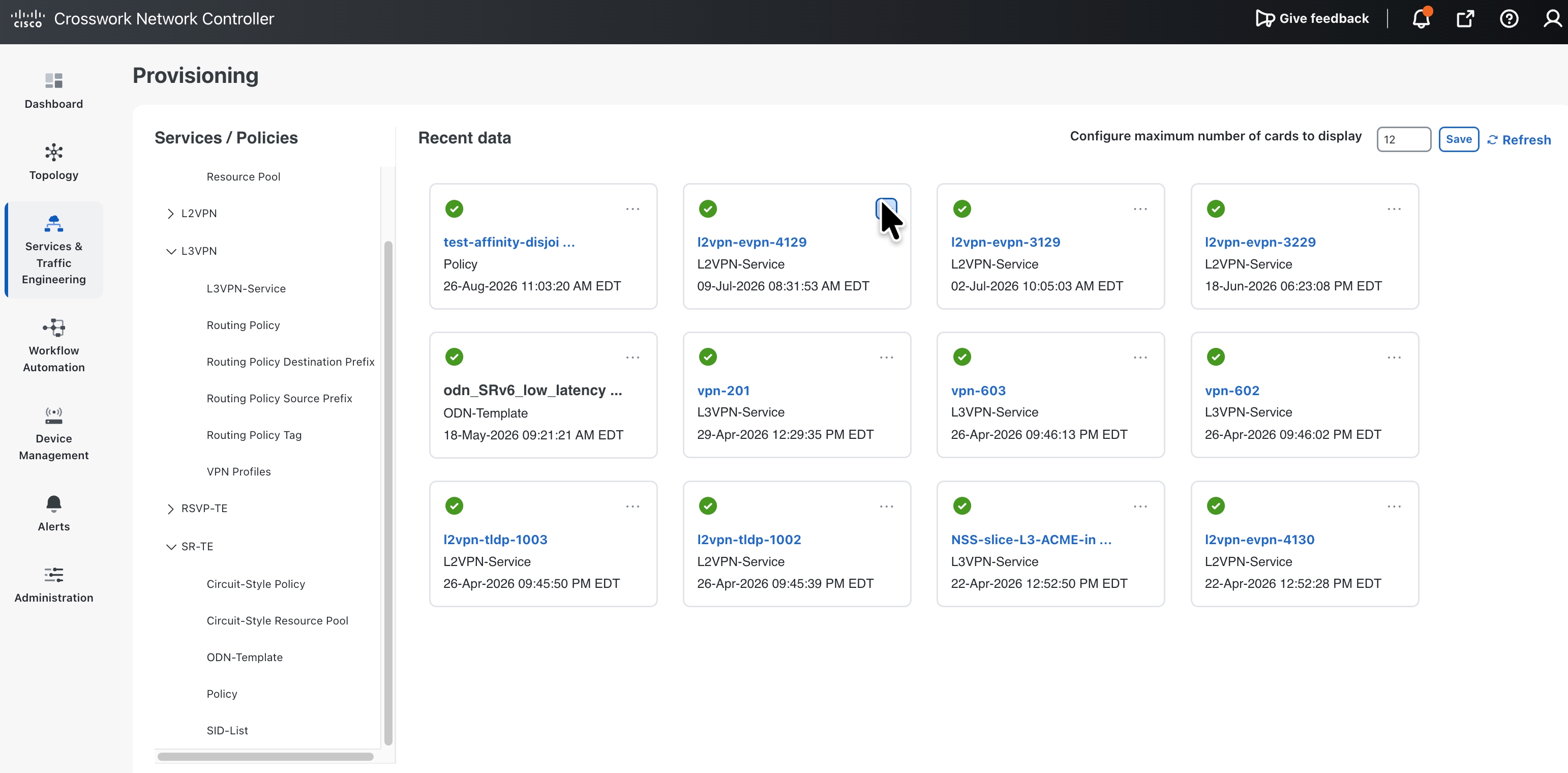
Inference Service Provisioning
7.3.1.1. Transport slicing automation for AI Inference services
Crosswork supports the concept of a transport slice service – in short, a slice service is a composed provisioning of 4 key pillars of a slice;
● a VPN flavor to provide end to end network partitioning
● SLA specific underlay using either SR-TE or FlexAlgo
● Edge QoS
● Service assurance key parameters to compare against measured values such as delay, delay variation, loss and availability etc.
The service designer creates these slice templates in a catalog, and the service provisioner just needs to pick the right catalog entry for a customer. For AI inference, this model is directly applicable. A provider can define AI-specific slice templates such as:
● Low-latency AI inference slice for real-time agents and copilots.
● Sovereign AI inference slice for regulated workloads that must remain within a country.
● Secure AI inference slice requiring mandatory steering through AI security and DDoS protection functions.
● High-availability AI inference slice with disjoint primary and backup paths.
● Cost-optimized AI inference slice for non-real-time workloads.
The slice catalog abstracts the complexity of the transport network. A service requestor selects a slice intent, identifies endpoints, and submits the request. Crosswork automates the creation of the underlying VPN, SR policy, SR-PM monitoring, QoS, and transport constructs required to realize the slice. This allows providers to offer AI transport as a productized service. Rather than building one-off designs for each customer, they can create reusable AI slice templates aligned with commercial tiers and technical requirements.
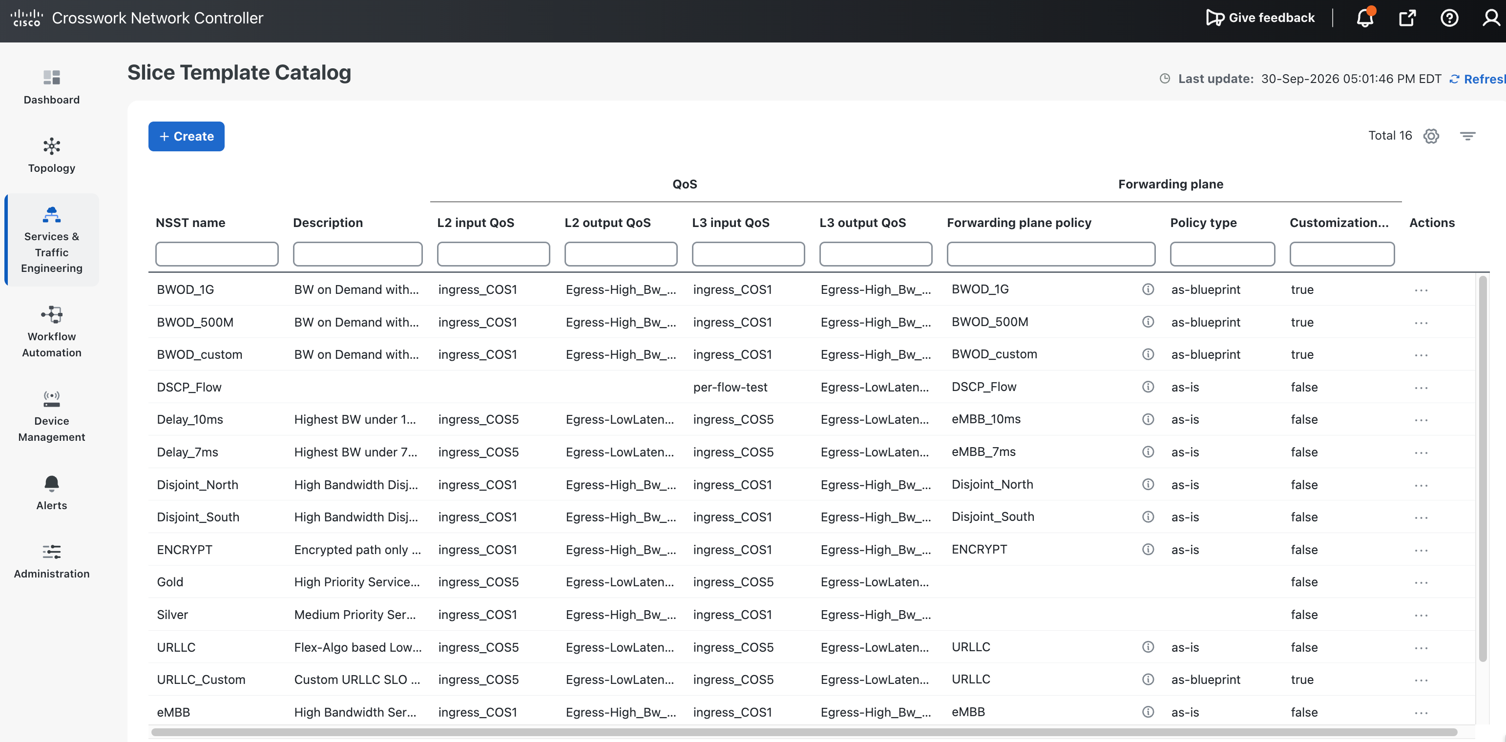
Inference Slice Template
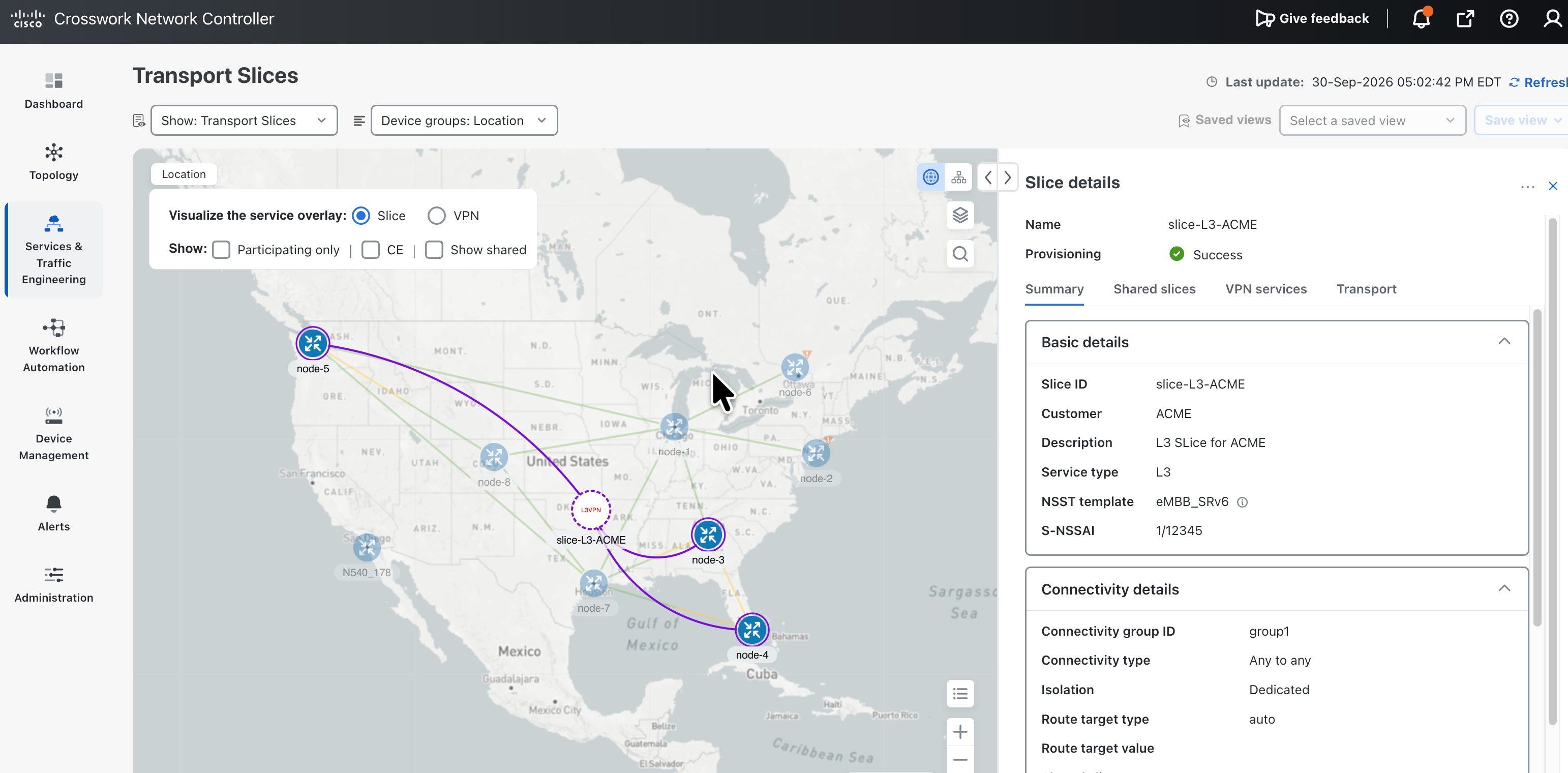
Inference Slice Automation View
7.3.2. Traffic engineering and path optimization for AI Inference
AI inference traffic can be highly sensitive to different requirements such as; latency, congestion, path instability and requires quick path recalculation when the current path cannot support the required SLO. In section 4, the multi-plane network was described which will use SRv6 IGP Flexalgo and in this case the network and the IGP (ISIS) will automatically update based on topology changes such as link up/down or latency changes triggered by underlying optical path changes.
Crosswork Network Controller includes a stateful path computation engine and telemetry collection engine to address path computation and always on real time optimization for traffic engineered paths.
The path computation model allows the controller to compute SR policies based on objectives such as latency minimization, IGP or TE metric minimization, affinity rules, and disjointness. In an AI Inference Cloud, these objectives map directly to inference service tiers:
● Low-latency inference uses latency-aware path computation to minimize delay between enterprise users and inference endpoints.
● High-availability inference uses disjoint path constraints to reduce correlated failure risk.
● Bandwidth-aware inference uses utilization-aware computation to avoid congested paths.
● Sovereign inference can use affinities or topology constraints to avoid prohibited regions or infrastructure domains.
● Cost-optimized inference can use metric-based paths where strict latency is not required.
Crosswork can also support real-time continuous optimization. When topology changes occur, or when bandwidth utilization changes, the controller can recompute paths and update SR policies through SR-PCE. This capability is especially important for inference workloads because network conditions can change while the AI service remains active. A path that satisfies a latency or bandwidth objective in the morning may no longer satisfy it during an evening traffic peak.
In practical terms, this allows providers to operate an AI-aware transport fabric where traffic is not simply forwarded based on static shortest path routing. Instead, AI traffic can be mapped to transport paths that reflect the service intent. Premium inference flows can receive low-latency treatment. Standard inference flows can use default paths. Resilient inference services can use protected or disjoint paths. Sensitive inference services can be constrained to approved transport domains.
This makes the network programmable and service-aware, which is essential for differentiating provider inference offerings from generic cloud API access.
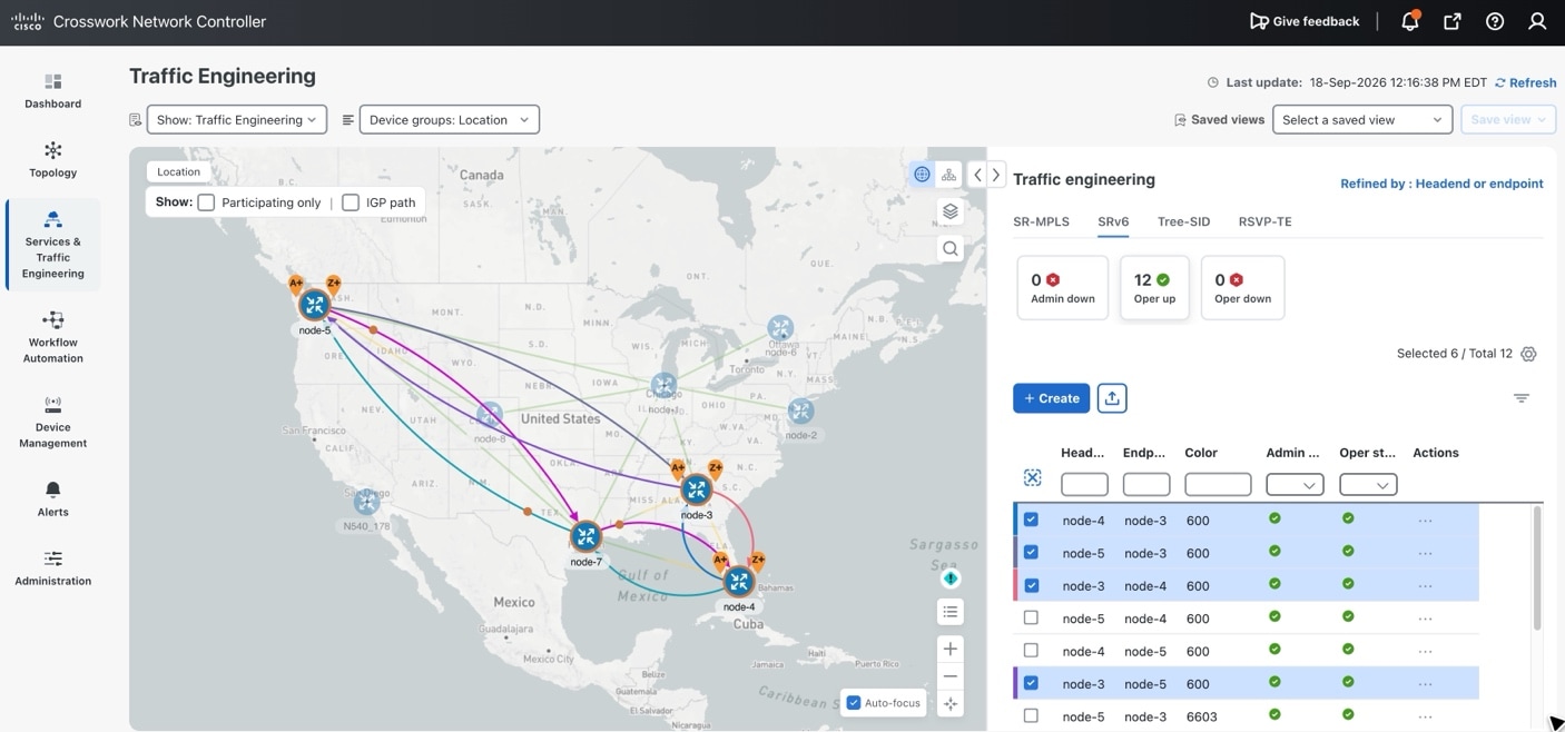
Inference Traffic Engineering Path
7.3.3. Service health monitoring orchestration
Another important automation element for AI inference is to monitor the service to assure it is meeting the SLO – this requires both monitoring service specific operational states on routers and the traffic path. Additionally, by doing service aware checks, potential issues in the context of the service can be highlighted pinpointing the location to troubleshoot and fix
● Operational state monitoring requires checking of health of things like PE-CE interfaces, PE-CE BGP session health, VPNV4/V6 iBGP session health between PE-RR, PCEP session when SRv6TE is being used and so on. When the service is provisioned, Inference networking KPIs are also automatically collected and used to calculate and provide a service health indication of good/degraded/down.
● Traffic path monitoring is typically done by actively sending traffic on the service path at low rates. This requires either to use in-router or external to router synthetic traffic sessions such as TWAMP or Y.1731 that can for the duration and life of the service measure KPIs such path delay, delay variance, drops and multiple such parameters, and report when these are above the set threshold.
7.3.4. Operational visibility and lifecycle operations
AI Inference Cloud would use multiple logical transport planes over a shared physical network. One plane may be optimized for low latency. Another may be optimized for cost. Another may support sovereign routing. Another may provide disjoint paths for mission-critical workloads. Flex-Algo and SRv6 provide the network mechanism for creating these intent-specific planes; Crosswork provides the visualization, control, and operational visibility required to use them at scale.
Crosswork Network Controller includes SRv6 Flex-Algo path visualization using Path Analytics. This allows the operator to view SRv6 and Flex-Algo paths in the context of VPNs between PE pairs, with path information exposed through UI and API.
For AI inference, this addresses a critical operational need: the operator must be able to see which transport plane is carrying which service. If a premium AI service is supposed to use the low-latency Flex-Algo plane, the controller should make that visible. If a sovereign inference service is supposed to avoid specific regions, the controller should help validate the path. If a customer reports degradation, the operator should be able to drill down from the service to the VPN, from the VPN to the transport policy, and from the policy to the underlying path.
This visibility also supports troubleshooting and audit. AI services may be subject to contractual SLAs or regulatory requirements. A provider must be able to demonstrate that the service was carried over the intended path class and that path behavior matched the service intent. Flex-Algo visualization and path analytics make this operationally feasible.
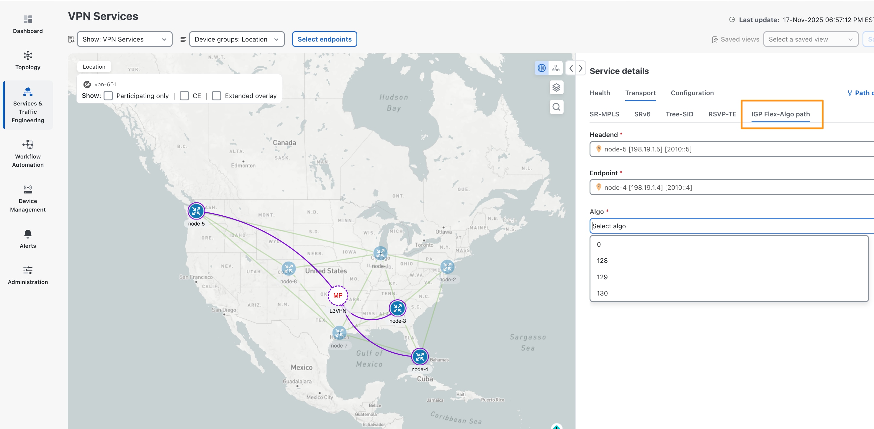
Inference Path Visualization for Flex-Algo
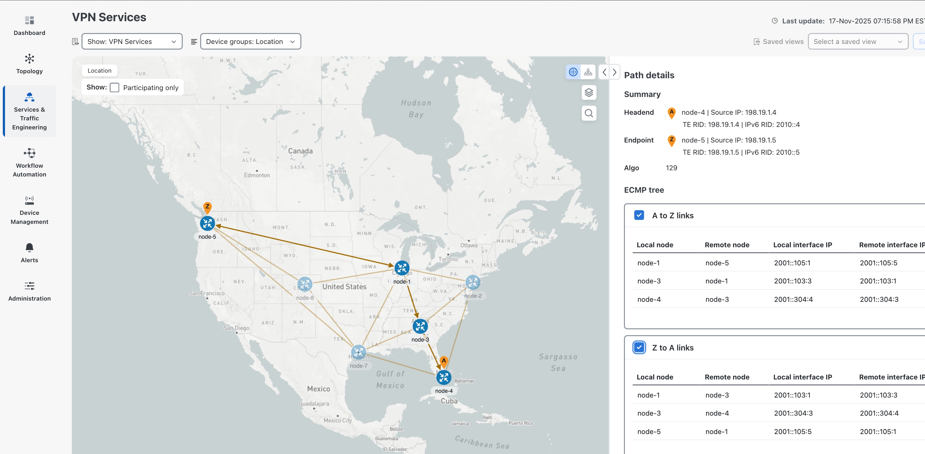
Inference Path Details
7.3.5. Automated capacity planning for AI Inference readiness
AI inference services require proactive capacity planning. It is not enough to know whether the network is healthy today. A provider must understand whether the network can survive failures, traffic growth, maintenance events, and regional demand shifts without violating AI service SLAs.
Crosswork Automated Capacity Planning uses the latest routing topology and demand matrix, optionally applies growth factors, simulates traffic under link, node, and SRLG failure scenarios, and reports KPIs for detected congestion. The deck highlights the scale of this analysis: a network with hundreds of nodes and thousands of links can generate millions of simulated link-load data points.
For AI Inference Cloud, this type of what-if analysis is essential. The operator needs to answer questions such as:
● If a core link fails, will low-latency AI traffic still meet its SLA?
● If a metro node fails, which AI customers will be affected?
● If inference demand grows by 50 percent, where will congestion appear first?
● Which links are most likely to become congested under failure?
● Which failures create the most severe AI service impact?
● Should the provider add capacity, add redundancy, or move inference workloads?
Automated capacity planning shifts the operating model from reactive troubleshooting to proactive readiness. It allows the providers to identify risk before customers experience degradation. For AI services, this is especially valuable because degraded inference may appear to the end user as a slow or unreliable AI application, even when the underlying model is functioning correctly.
Capacity planning also informs infrastructure investment. Instead of adding bandwidth or GPU capacity based on static estimates, the provider can use demand and failure simulations to prioritize upgrades where they have the greatest impact on AI service resilience.
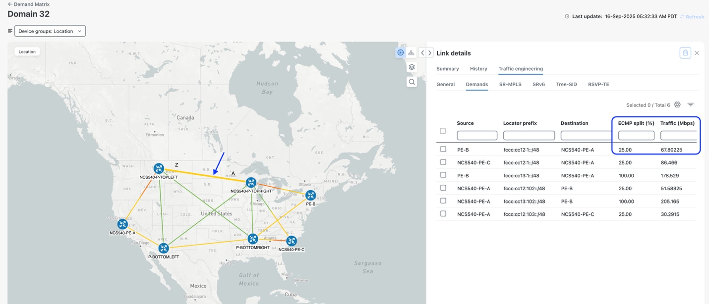
Inference Capacity Planning
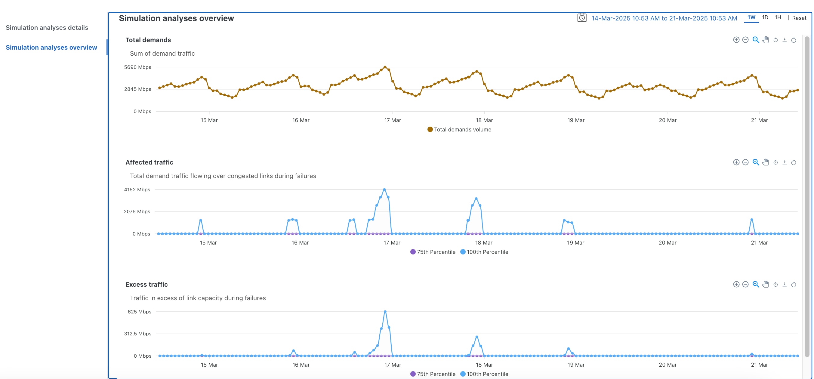
Inference Traffic Simulation and Analysis
7.3.6. AI for Inference network automation
7.3.6.1. Autonomous networks
Distributed AI inference makes Autonomous Networks operationally necessary, not optional. Inference SLAs depend on intent that changes with placement, sovereignty, congestion, and demand, at a speed that assisted or partial automation cannot sustain. TM Forum describes this maturity as a progression from manual operations (L0) through assisted and partial autonomy (L1-L2) to conditional autonomy inside a domain (L3) and highly autonomous, cross-domain operations (L4). In this blueprint, L4 is the operating target: the network must sense inference experience and path health, analyze the contributing domain, decide a bounded response, and execute under policy, with humans setting intent and approving exceptions rather than driving every change.
Cisco takes customers to that L4 posture through a staged closed-loop journey on the Crosswork stack already used for inference automation and assurance. Domain closed loops for transport, access, DCI, and AI POD connectivity are established first with intent-based provisioning, SR-PCE optimization, KPI-driven Health Insights, and programmable remediation, matching the TM Forum L3 pattern inside an autonomous domain. Cross-domain service loops then join those domains: Crosswork Network Controller, NSO, Workflow Manager, and Crosswork AI agents correlate TTFT, ITL, and network evidence, recompute or re-steer under policy, and verify the same SLO. Multi-agentic AI, federated telemetry, and operator-governed execution extend this from reactive playbooks toward predictive, self-healing, service-level closed loops, the shift Cisco associates with L4, so inference connectivity can be sold as an autonomous, SLA-backed service rather than a manually operated overlay.
7.3.6.2. Agentic framework for service providers and beyond
One of the fundamental building blocks to achieve L4 autonomy, according to TMF L4 Autonomy blueprint, are AI Agents. But AI agents do not run on vacuum. AI Agents need to operate in an environment where providers can manage their life cycle. Network operations trust in AI Agents must be based on clear transparency, visibility, reliable, predictable and measurable behavior, all in a context with strong security control and governance.
Cisco Crosswork AI is the framework intended for Providers to operate AI Agents in a trustable and reliable way. AI Inference services will require rapid response, proactive and preventive decisions, so offer the strict SLAs required. Humans alone will not be able to offer 24x7 strict SLAs that are required by non-stopping customer AI Agents. Only with the support of AI Agents can now network operation teams offer the levels of service required.
With Crosswork AI and the catalog of agents offered, including but not limited to, Providers will be able to perform:
● Preventive detection of configuration anomalies.
● Automatic identification of risk factors for AI Inference infrastructure.
● Rule-free event correlation into incidents.
● Autonomous network troubleshooting and root cause analysis using Deep Research agents.
● Remediation strategy definition and implementation
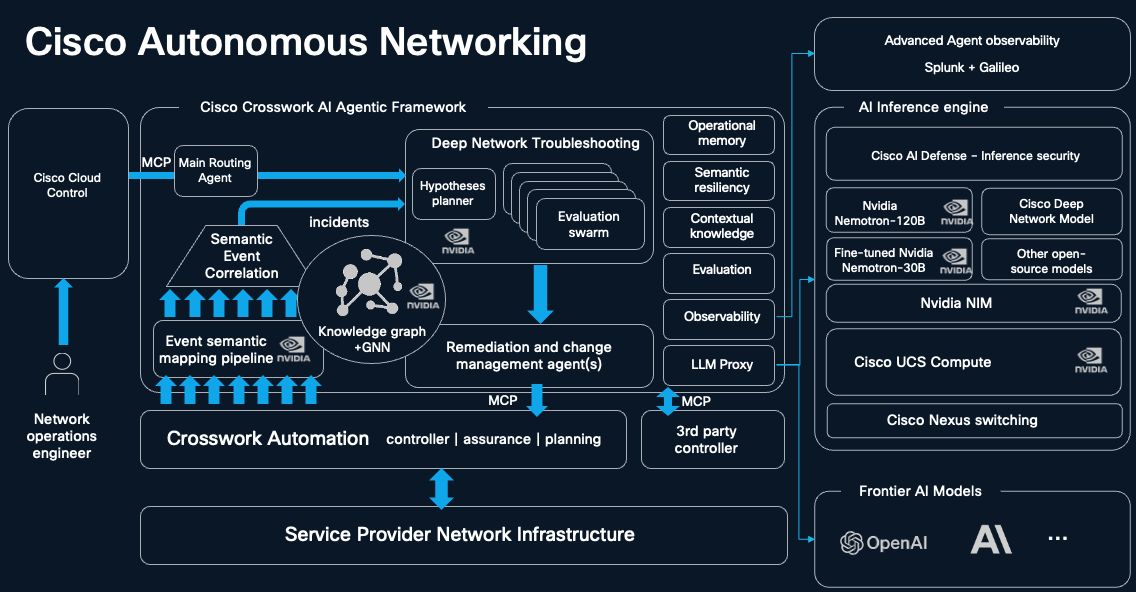
Cisco Autonomous Networking
7.4. Assurance for AI inference transport
Crosswork Assurance provides an outside-in view of the AI inference service across the entire service-provider-operated path. It correlates synthetic and real-user experience with active measurements, routing and topology information, device and Data Center Interconnect (DCI) telemetry, and relevant third-party evidence. A synthetic Assurance Large Language Model (LLM) Agent generates repeatable inference transactions, allowing the provider to measure service behavior consistently across endpoints, locations, workloads, and time periods.
The resulting assurance model combines application-facing inference metrics with network-delivery metrics. As summarized in the table below, these include inference availability, time to first token, inter-token latency, completion rate, response and queueing time, inference flow loss, network latency, jitter, packet loss, bandwidth, and endpoint or path health. Correlating these KPIs enables operations teams to determine whether degraded inference performance originates in the application, model-serving platform, AI gateway, DCI, WAN path, or access network, and to validate whether the customer’s service-level objectives have been achieved.
Table 8. Inference KPIs
| KPI |
Meaning |
Reporting guidance |
| Time to First Token (TTFT) |
Time from request start to the first output token; may include network transit, gateway handling, queueing, and prefill |
State the measurement boundary and workload shape |
| Inter-Token Latency (ITL) |
Time between streamed tokens |
Report percentiles such as p50, p95, and p99 to expose stalls |
| Time Per Output Token (TPOT) |
Average time per output token after the first token |
Use alongside ITL; averages can hide pauses |
| Tokens Per Second (TPS) |
Output rate for a single stream or all active streams |
Distinguish per-stream experience from aggregate capacity |
| End-to-end request latency |
Client-measured time from request start to completion |
Compare requests with similar input and output lengths |
| Completion and failure |
Success, timeout, cancellation, truncation, 429, and 5xx outcomes |
Distinguish complete, usable responses from unsuccessful or incomplete transactions |
7.4.1. Assurance data sources
Crosswork Assurance is the service and network assurance layer for the provider-operated path. It combines active and passive measurements with routing, topology, and device context to show which service is affected and where the network changed. For AI inference, the operating view also uses synthetic transactions from the Assurance LLM Agent and, when available, from platform exporters. These sources are joined for the same service and event that they do not all have to be stored in Crosswork Assurance. Each source answers a different question, and the measurement boundary and join determine how strong the operational finding can be. The reference design moves through five stages:
Table 9. 5 Stages of assurance
| Observe |
Add context |
Correlate |
Explain |
Act and report |
| Synthetic inference, real-user experience, network measurements, routing, gateway, and compute signals |
Time, customer and service, endpoint and backend, path and topology, location, workload shape, and request or trace ID when available |
Compare the same service and event across experience, path, routing, and compute evidence |
Identify a measured contributing domain, narrow the remaining possibilities, and state gaps |
Notify, report an SLO result, open an investigation, or start a policy-governed workflow |
Below are important datasets required to monitor distributed inferencing experience:
7.4.1.1. Assurance LLM Sensor
The Assurance LLM sensor is a controlled probe that sends real inference transactions to a selected model over a known egress path. It measures the transaction as a user would experience it. The declared workload and path make the test repeatable. It can run the workload profiles from Section 1.1 before a service has customers, which supports pre-launch capacity and SLO testing. The resulting measurements provide a controlled basis for an SLO and distinguish a slow response start from degraded streaming, giving operations the first branch in an investigation.
Key indicators: Time to First Token - TTFT, Inter token latency - ITL, Time per output Token - TPOT, per-stream TPS, end-to-end latency percentiles, completion and failure rate.
7.4.1.2. Crosswork assurance user experience
Crosswork Assurance User Experience provides passive evidence for subscriber traffic without depending on model-provider compute telemetry. It can organize experience by user cohort, access or cell-site context, application, provider, and region. Compared with the controlled synthetic result, this population view shows whether a condition is widespread, limited to a cohort, or specific to the probe.
Key indicators: customer-experience score, congestion ratio, burst throughput, TCP round-trip time, retransmission, and per-application or per-provider volume.
7.4.1.3. Active network monitoring - TWAMP
Crosswork assurance TWAMP sensor provide standards-based active measurement of the transport path, independent of production inference traffic. These Twamp Sessions can cover access, aggregation, core, peering, and DCI segments. They can also test the class of service used by the inference offer. This can reveal path degradation before users report it and provides a continuous record for each monitored SP segment.
Key indicators: one-way delay; packet-delay variation; Jitter, packet loss and burst loss; reordering; availability; and class-of-service compliance.
7.4.1.4. Transport telemetry
Telemetry from network devices such as Segment Routing Performance Measurement (SR-PM), and optical or DCI signals show the state of the devices and links carrying the traffic. Used with active measurements, these signals help locate the layer, device, queue, or optical link associated with a path change.
Key indicators: interface and fabric errors, drops, utilization, queue depth, queue drops, segment or link delay and loss, optical power, pre-FEC bit-error rate, and DCI link health.
7.4.1.5. Third party and multivendor telemetry data
Provider networks, probes, optical domains, gateways, and inference providers are not all supplied by one vendor. Crosswork Assurance can ingest supported third-party and multivendor evidence so that external telemetry, probes, and provider-facing data can be used in the service view. The combined view exposes coverage gaps at domain boundaries and preserves the measurement boundary, timestamp, identity mapping, and source link needed to interpret each record.
7.4.1.6. IPM - IP Measurements
AI traffic can make sampled monitoring incomplete. One degraded ECMP member can affect many token streams while the aggregate average still appears healthy. IP Measurements (IPM) moves probing from software or hardware sensors into forwarding silicon. On supported Cisco Silicon One systems, a device can generate and ingest probes at up to 14 million packets per second per NPU and record each result. This supports continuous measurement across ECMP paths. Each measurement carries the 3L view of latency, loss, and liveness.
Three capabilities matter for inference:
● Latency histograms. A 28-bin distribution shows tail delay and microbursts that an average can hide. These events can create visible streaming stalls.
● Direct interval loss using alternate marking. Per-interval packet accounting helps connect retransmission and ITL gaps to a transport event.
● All-path coverage and liveness. Per-customer and per-path measurements can expose a degraded ECMP member that sampled probing misses. With weighted load balancing, the impact also depends on the member's traffic share.
The implementation uses standards such as STAMP measurement and alternate marking, which support directional and interoperable designs. This path-specific evidence helps operations find a degraded ECMP member that sampled or aggregate monitoring can miss and confirm whether an alternate path is healthy.
7.4.1.7. Routing analytics
Routing analytics is important for AI inference because inference applications are sensitive not only to average latency, but also to latency variation, packet loss, jitter, and tail latency. A single degraded path can affect a subset of inference flows, causing delayed tokens, request timeouts, retries, or inconsistent user experiences while aggregate network metrics continue to appear normal. Routing analytics provides the path-level context required to connect these inference symptoms to the specific network conditions causing them.
Crosswork Assurance correlates each IP Performance Measurement (IPM) session and measurement interval with the corresponding ECMP tree derived from Routing Analytics. This allows operators to compare measured inference-path delay with the expected propagation baseline, identify the paths active during an event, and determine whether degradation is isolated to a specific ECMP member. ECMP drill-down provides the member paths, hop-level expected delays, path-change history, and path comparisons needed to narrow the investigation.
7.4.2. Assurance Instrumentation for the Inference
The assurance design is instrumented on the same access, metro, backbone, DCI, and peering architecture that carries the inference service. It does not create a parallel monitoring network. Its primary assured flow is the inference transaction from the enterprise application or agent to the selected model endpoint and back. The Assurance LLM sensor and User Experience sensor measure the application service as experienced by users. IPM and TWAMP measure the delivery path at selected boundaries. Routing Analytics adds topology with ECMP context. MDT, SR-PM, and optical or DCI telemetry identify the network objects that explain a path change. At an SP AI POD, gateway, serving, Kubernetes, and GPU signals extend the same view into compute.
The transport-slice service model provides the intent that connects these observations. Crosswork Network Controller can supply the customer and service identity, endpoints, SLO or SLE, VPN or VRF, QoS treatment, SLA profile, and the forwarding-plane policy used by the slice. In the inference backbone design, the service prefix and BGP color steer the request into an SRv6/Flex-Algo inference plane. This configuration identifies the expected treatment; active measurement and telemetry show whether the delivered path met it.
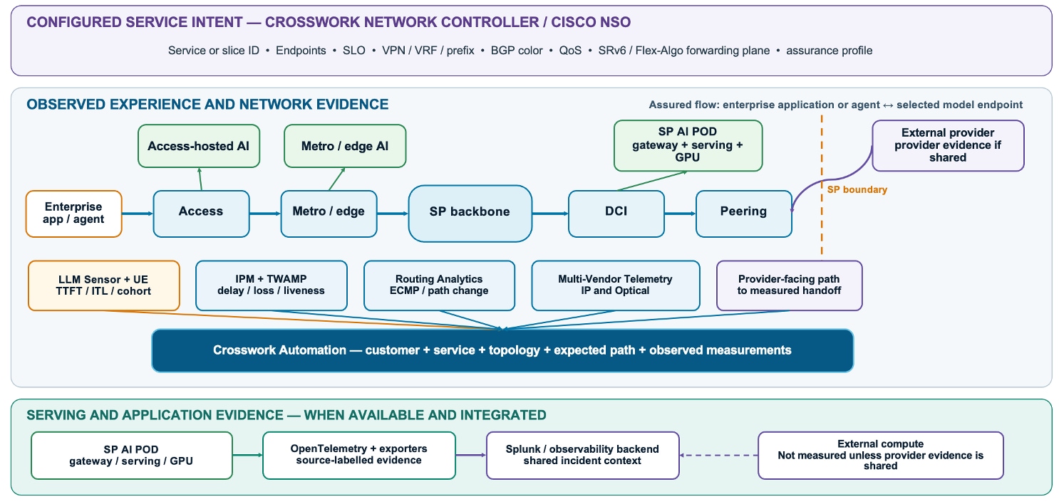
Assurance Instrumentation for AI Inference
Table 10. Assurance instrumentation placement
| Backbone vantage point |
Evidence collected |
Operational use |
| Enterprise and access |
Assurance LLM sensor transactions, User Experience application evidence, access IPM or TWAMP sessions, and service identity |
Confirms the symptom and shows whether it affects one model test, one customer population, or a wider access area. |
| Metro and backbone |
Transport-slice intent, service prefix and color, the routed ECMP tree and path changes, IPM or TWAMP results, and Telemetry (gNMI) or SR-PM |
Relates the service to its expected inference plane, narrows degradation to a measured segment or path, and identifies the network object to investigate. |
| DCI and AI POD |
DCI and optical state, gateway decision, model endpoint, queue, prefill, decode, Kubernetes, and GPU signals |
Connects transport performance with the selected backend and serving system when the SP operates the AI POD. |
| Peering and external provider |
Provider-facing IPM or TWAMP, peer and route context, selected egress, and shared provider telemetry when available |
Measures the SP-controlled path to the handoff and records the point beyond which provider processing is not measured. |
Crosswork assurance uses its service model and topology information to relate these measurements to customer service and the network objects that deliver it. Metadata aligns supported external sources with that context. The sources do not need to reside in one product. They only need to describe the same service, workload, endpoint decision, path, and time window so that operations can use them as one incident record.
7.4.3. Building and using the incident evidence pack
An inference symptom becomes actionable when it is tied to the affected users, the selected endpoint, the expected transport treatment, and the measurements from the path that carried the service. Crosswork Assurance provides that service and network context. The Assurance LLM sensor supplies a repeatable experience result, User Experience shows the affected population, IPM or TWAMP measures the relevant path, and Routing Analytics relates the result to the route, policy, routed ECMP tree, expected paths, and path changes. MDT from SR-PM, DCI, and optical nodes then locate the network object associated with the change. For SP-hosted inference, Splunk adds the gateway, serving, Kubernetes, and GPU view.
The resulting evidence is a logical incident record assembled from the available sources. It keeps the information needed to make and explain an operational decision:
● Service and intent: customer, service and tier, SLO, workload profile, endpoint or provider, and the transport-slice identifiers and forwarding policy.
● Time, vantage, and provenance: incident window, sensor location, affected cohort, source-record links, clock quality or join tolerance, and data freshness.
● Delivery and serving: route and topology context, IPM or TWAMP result, routed ECMP tree and expected paths, measured member when the session is bound, affected interface, queue, link, DCI or optical object, and gateway or compute evidence when available.
● Decision record: supported finding, attribution confidence, unavailable sources and coverage gaps, next test or approved action, verification result, and rollback or escalation outcome.
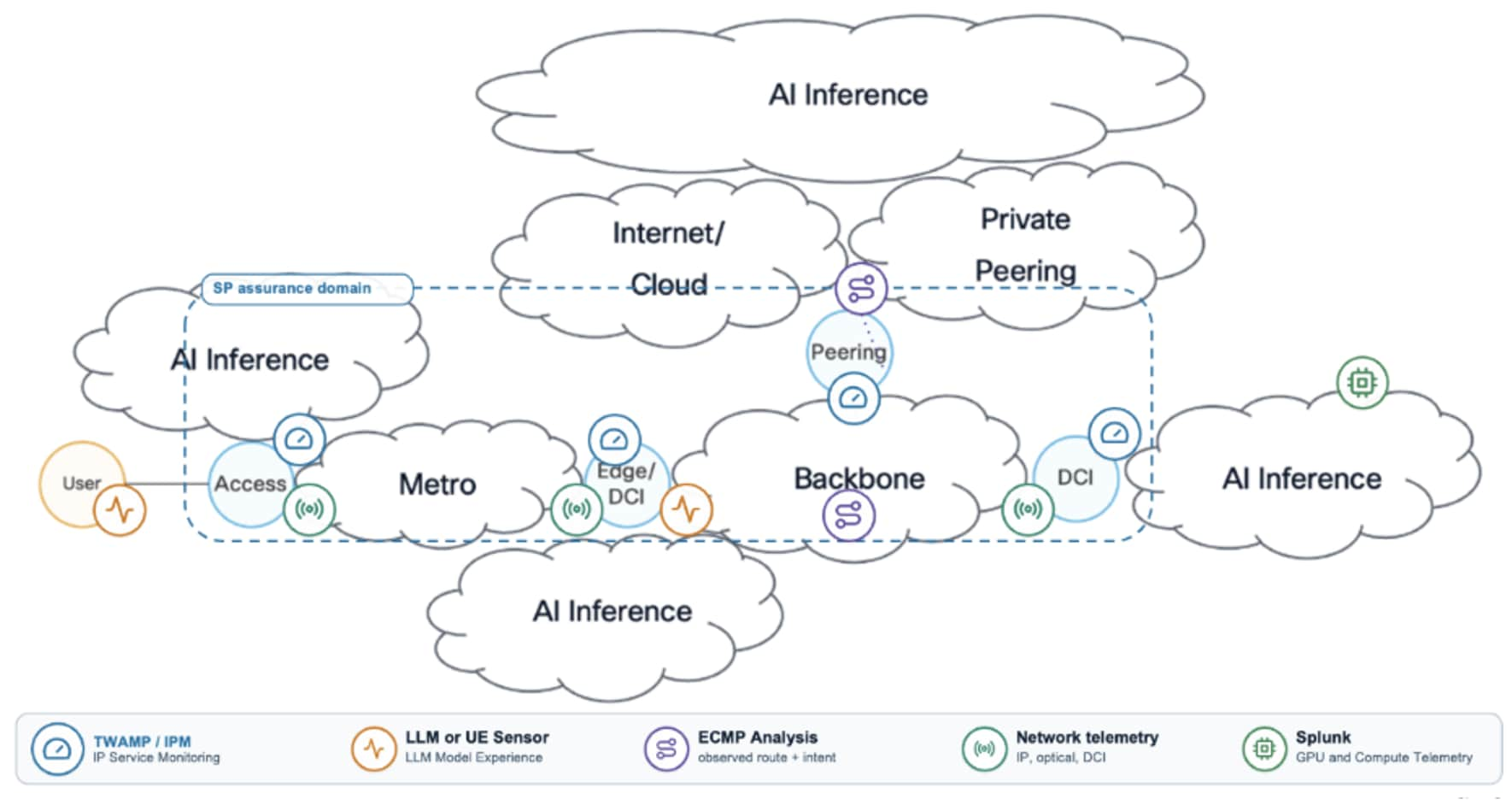
Evidence flow for an inference service
Figure 3 shows the instrumentation of assurance including what type of data is collected from which domain to meet the SLA visibility and operational use cases.
The operational workflow follows the evidence supported by assurance data during the events of degradation of SLA objectives. A higher TTFT or ITL first identifies the affected model test or user cohort. The service and transport-slice context bind that symptom to the selected endpoint, route color, and inference plane. IPM or TWAMP shows whether delay, loss, or liveness changed on the relevant segment. Routing Analytics supplies the routed ECMP tree, expected paths, and path changes, while forwarding or measurement-session evidence identifies a specific member when available. Device telemetry locates the interface, queue, link, or DCI object. Gateway and GPU evidence is added for an SP-hosted backend. The operator then chooses the supported owner or next test, applies an approved response, and measures the same service objective again.
For example, if the Assurance LLM sensor reports higher TTFT and User Experience shows that the same change affects users following one provider-facing egress, IPM can identify a concentration of delay or loss on the measured ECMP paths within its configured scope. Routing Analytics shows the routed tree, expected paths, policy, and recent path changes; IPM session or forwarding evidence binds the measurement to a member; and MDT identifies the affected interface or queue. A verified alternate can then be selected through the approved CNC or Cisco NSO workflow, followed by configuration changes to resolve the routing issues. Crosswork assurance can finally be used to verify that the change delivers expected SLA for latency and loss.
A different pattern applies when one model degrades, but the wider user population and SP path remain healthy. User Experience determines whether the symptom is isolated to the tested model, endpoint, or workload. For an SP-hosted AI POD, gateway queue, prefill, decode, Kubernetes, and GPU telemetry can identify a serving-system contribution. For an external provider, the same evidence pack stops at the measured handoff unless provider telemetry is shared.
Table 11. Crosswork Assurance evidence patterns
| Evidence pattern |
Supported operational decision |
Next step and verification |
| Network-path contributor — Inference experience and the affected cohort degrade; IPM or TWAMP shows delay, loss, or liveness outside objective; route and telemetry context locate the segment or object. |
Assign the incident to access, metro, backbone, DCI, or peering according to the measured segment. |
Repair the object or test a verified alternate path. After an approved change, remeasure both the path objective and the user-facing KPI. |
| SP-hosted serving contributor — TTFT, ITL, completion, or failures degrade while the monitored path remains within objective; gateway, queue, prefill, decode, Kubernetes, or GPU evidence changes for the same workload and window. |
Assign the incident to the gateway or serving platform with the network result attached. |
Apply the authorized capacity, placement, or backend response and verify the same workload-specific SLO. |
| External provider without serving telemetry — The symptom is confirmed, but every relevant monitored SP segment to the handoff remains within objective, and provider evidence is unavailable. |
Record Evidence of Monitored-Domain Performance, sometimes called Proof of Innocence. |
Send the scoped incident and SP path evidence to the application or provider team; continue testing from the same vantage point. |
| Multi-domain degradation — User experience, one or more network segments, and available gateway or compute signals change together. |
Treat the event as a multi-domain rather than forcing a single owner. |
Coordinate recovery across the affected teams and close only after the original SLO recovers from the same service vantage points. |
In this reference design, the Crosswork AI Agent can explain the degradation symptoms as listed in table above under Evidence pattern and recommend the next action. Deep Network Troubleshooting (DNT) Agent can examine a difficult network case using the service, topology, measurements, and identified gaps. Deterministic policy, impact checks, and operator approval govern execution through CNC, Cisco NSO, or another authorized workflow. The controller reads back the applied change; Crosswork Assurance measures the original objective again, and the workflow records whether service recovered, must be escalated, or requires a pre-approved rollback.
7.4.4. Reduce MTTR with Crosswork automation portfolio
Fast Mean Time to Repair (MTTR) is especially important for AI inference because even short network disruptions or performance degradations can affect interactive applications, digital agents, and business-critical workflows. Delays may trigger request timeouts, retries, and duplicated inference traffic, which can increase congestion and amplify the original problem. A prolonged issue can therefore degrade user experience, reduce application accuracy or responsiveness, and lead to violations of customer Service-Level Objectives (SLOs).
Crosswork Network Controller provides dashboards for network events, alarms, and performance monitoring based on Threshold Crossing Alerts. These capabilities give operations teams timely visibility into when an AI inference service is degraded, which customers or workloads are affected, and where the problem is located in the service path. The controller also provides severity indicators in topology views, device- and interface-specific alarm views, and external notifications to the provider’s Operations Support Systems (OSS).
This visibility helps reduce MTTR by connecting a service-impacting inference issue to the specific network segment or device responsible for it. For example, if an overlay Two-Way Active Measurement Protocol (TWAMP) session between a customer site and an inference site reports packet loss, and the corresponding Provider Edge-to-Customer Edge (PE-CE) interface also reports packet drops, the operations team can begin troubleshooting at that interface. Addressing the PE-CE issue first may restore the inference service more quickly than investigating the model or inference platform prematurely.
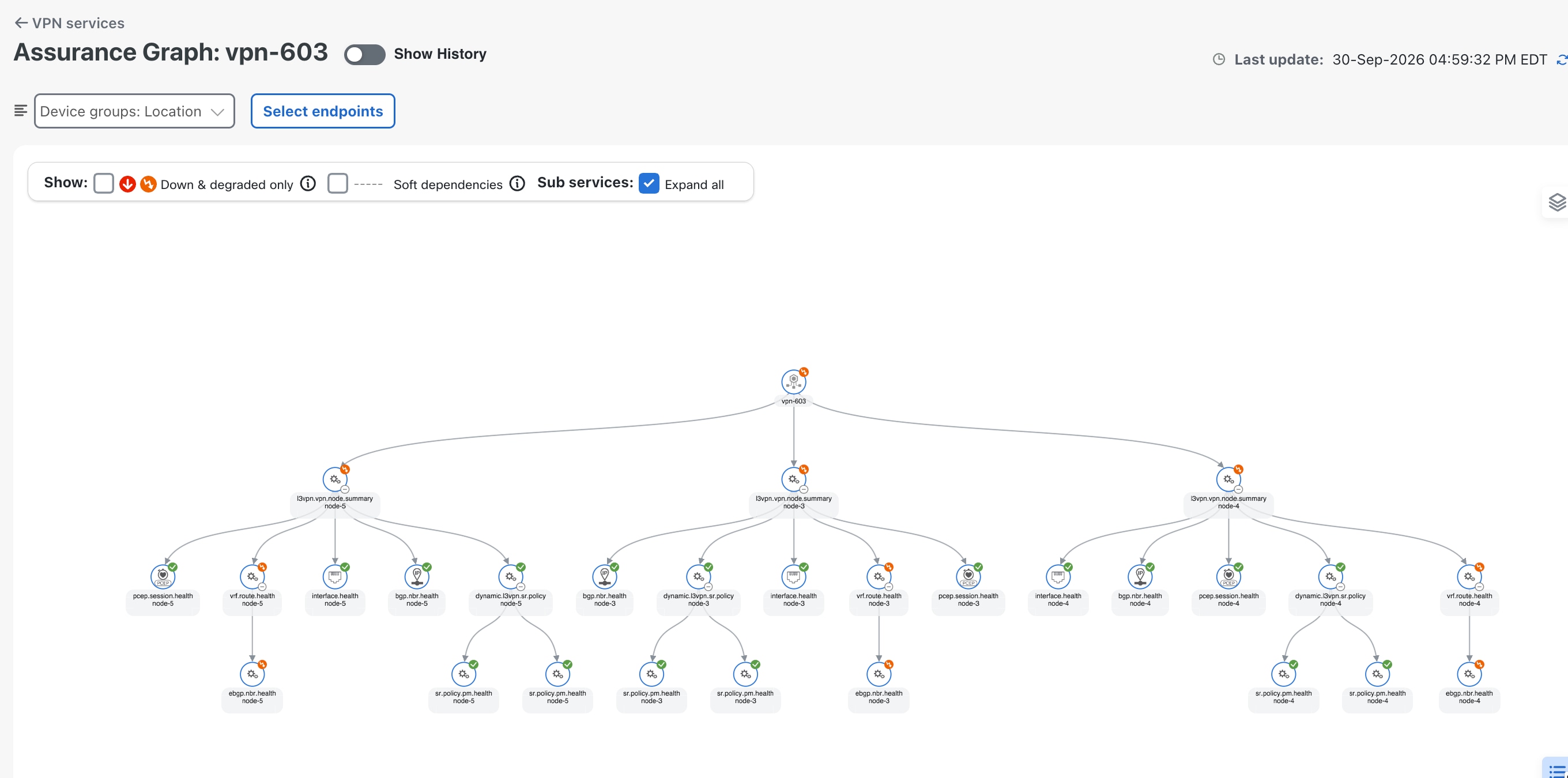
Assurance Graph for Faster MTTR
7.5. Building an SP inference service portfolio
Automation and assurance together allow an SP to define, deliver, and operate inference services with measurable commitments. A Service-Level Objective (SLO) is the target measured by the assurance platform for a declared workload and boundary. Automation instantiates the connectivity, slice, and path that make that objective achievable, and it executes the approved act-and-verify step when evidence supports a change. A Service-Level Agreement (SLA) turns selected objectives into a customer commitment and adds scope, exclusions, reporting, response times, and commercial terms.
The commitment depends on the service boundary. When the model runs at an external provider, the SP can offer an SLA for the monitored network path to the provider handoff and report the inference experience seen by its users. Provider processing remains outside the SLA unless the provider shares suitable telemetry and operating responsibility. When the SP hosts the model in an AI POD, the boundary can extend through the gateway, serving platform, and GPU infrastructure.
The Cisco automation and assurance model supports the following SP service offers:
Table 12. Supported provider service offers
| SP service offer |
Customer proposition |
How Cisco assurance supports the service |
| SLA-backed inference connectivity |
Measured availability and network performance from enterprise access to the provider handoff, with inference-experience reporting for a declared workload and measurement point. |
The Assurance LLM sensor and User Experience show the delivered experience. TWAMP, IPM, Routing Analytics, and path telemetry identify access, transport, peering, or DCI problems. CNC can apply an approved network action, and Crosswork Assurance verifies the SLO afterward. The automation stack provisions the inference path and slice so that this connectivity can be offered as a productized service. |
| Differentiated Model as a Service tier |
Interactive, throughput, premium, sovereign, or edge-hosted tiers defined by model, workload shape, TTFT, ITL, availability, capacity, and placement objectives. |
Crosswork Assurance connects network and user-experience evidence with gateway decisions, queue, prefill, decode, KV-cache, Kubernetes, and GPU data from the SP-hosted platform. Operations can adjust an authorized gateway, network, or compute policy and verify the selected tier. CNC, NSO, or an authorized service workflow execute that policy change, then the same tier SLO is remeasured. |
| Highly available distributed inference |
The service remains within its availability and latency objectives when a path, peer, backend, or AI POD degrades. |
IPM liveness and all-path coverage, Routing Analytics, backend health, alternate-path tests, and synthetic measurements identify the affected path or location. Policy can move traffic to a verified healthy alternative, followed by measurement from the same service vantage points. CNC and NSO implement that movement as a policy-governed automation action. |
| Sovereignty and placement assured inference |
Requests use an approved region or serving tier and do not move to a remote location without detection. |
Gateway decisions are checked against approved endpoints, observed paths, Routing Analytics, and location anchors. When a request is off-policy, automation can steer traffic onto an approved path or endpoint, and assurance rechecks placement. |
| Managed inference assurance |
Per-customer SLO reports, incident ownership, response tracking, and evidence of whether monitored SP domains met their objectives. |
The incident record connects experience, network, gateway, and compute evidence. Crosswork AI supports investigation; dashboards, APIs, and incident reports provide the customer record. Approved recovery actions are executed by the automation stack, and the customer record includes whether the SLO was restored. |
These offers form a service ladder. An SP that provides connectivity to an external model can start with automated path and slice provisioning, path assurance, user-experience reporting, and clear incident ownership. An SP that operates the AI POD can add model-specific performance tiers, capacity objectives, placement guarantees and coordinated network and compute recovery through closed-loop automation. In both cases, the SLA must match the domains the SP can measure, automate, and operate.
AI inference is becoming a distributed service, shaped by where users, data, models, and available compute are located. A WAN architecture for inference must therefore do more than connect sites. It must help Providers (service providers and neoclouds) place workloads across far-edge, metro, central, and external cloud locations, then connect those locations to enterprise and consumer users with the right performance, security, and policy controls.
This blueprint brings those requirements together in a programmable architecture. Routed optical transport and SRv6 provide the foundation for connecting distributed inference sites and carrying both data center interconnect traffic and user access traffic. Flex-Algo, traffic engineering, and service overlays allow paths to reflect different needs, such as latency, bandwidth, resilience, isolation, and jurisdiction. The four-tier placement model gives providers flexibility to run each workload where its latency, capacity, cost, data gravity, and sovereignty requirements can be met.
Connectivity alone does not make an inference service trustworthy or operable. Prompts, responses, and related data need protection in transit, while platforms and endpoints need security, isolation, and availability controls. Providers also need a way to measure the experience across the service boundary. By correlating inference measures such as time to first token and inter-token latency with network paths, gateway behavior, and available compute telemetry, assurance can help teams identify where degradation occurs and what evidence is still missing. Automation can then provision services and slices consistently, support policy-governed recovery, and verify whether the original objective has been restored.
The service commitment must match the provider’s operational reach. Where inference runs in an external cloud, the provider can measure and report on its own access, transport, peering, and interconnect domains; commitments for model processing require visibility and shared responsibility beyond that boundary. Where the provider hosts the inference platform, the service can extend further into the gateway and compute environment.
Providers can build toward this model in stages: establish measurement and visibility, connect enterprise workloads and inference locations, add policy-based optimization and security, and expand into sovereign services with defined performance commitments. The result is a WAN designed to support inference as a distributed, measurable service—and a practical foundation for evolving that service as workloads, capacity, and customer requirements change.