Integrating Isovalent Private Networks with Cisco Nexus One White Paper
Available Languages
Bias-Free Language
The documentation set for this product strives to use bias-free language. For the purposes of this documentation set, bias-free is defined as language that does not imply discrimination based on age, disability, gender, racial identity, ethnic identity, sexual orientation, socioeconomic status, and intersectionality. Exceptions may be present in the documentation due to language that is hardcoded in the user interfaces of the product software, language used based on RFP documentation, or language that is used by a referenced third-party product. Learn more about how Cisco is using Inclusive Language.
Running virtual machines and containers side by side on a single Kubernetes/Red Hat OpenShift orchestration layer is becoming more common. Isovalent Networking for Virtualization (INV), part of the Isovalent Enterprise Platform and built on the eBPF-based Cilium Container Network Interface (CNI), extends consistent networking, security, and observability across both workload types, giving Virtual Machines (VMs) the same policy engine, observability, and multinetwork capabilities as containers through a single unified architecture.
Today, INV enables connectivity and policy for VM workloads.
Cloud-native platforms may offer the capabilities to run VMs already, but may have limitations or implementation gaps compared to your existing traditional VM infrastructure.
INV also opens up a migration path, allowing customers to move VMs from traditional virtualization environments onto Kubernetes clusters in a controlled and staged manner.
Disclaimer — forward-looking statements: The future capabilities described above represent current plans and intentions, are subject to change without notice, and do not constitute a commitment or guarantee of future functionality or timelines. Design and purchasing decisions should be based on currently available features.
This paper describes how to integrate Isovalent Private Networks (IPN), a component of INV that offers a Virtual Private Cloud (VPC)-style networking construct, with a Cisco® data center fabric, covering:
● Cisco NX-OS (classic LAN/VXLAN Ethernet VPN [EVPN] fabrics)
● Cisco ACI® (Application Centric Infrastructure)
This document is organized into two main parts: an architecture section that explains the design — the concepts, traffic flows, and connectivity models, as well as the rationale behind each decision — and a configuration and implementation section that provides the concrete reference configurations needed to deploy it on both the Cisco fabric and the INV side.
The goal is to give VM workloads native, segmented reachability into an existing Cisco routing domain while preserving the operational and performance benefits of eBPF.
Isovalent Private Network handoff options and Nexus One fabric
As described later in this document, an IPN reaches the fabric's internal or external resources through a set of pluggable handoff options:
● VXLAN EVPN: Standards-based Layer 3 reachability using Border Gateway Protocol (BGP) EVPN Layer 3 Virtual Network Identifiers (VNIs), allowing the cluster to participate in the data center routing domain.
● Local Access (VLAN): 802.1Q tagged ingress/egress, delivered as a distributed function across worker nodes
NX-OS can terminate both the VLAN-based handoff and the VXLAN EVPN handoff, making it the appropriate choice when standards-based EVPN host-route advertisement (/32 IPv4 and /128 IPv6) directly into the fabric is required.
ACI supports the VLAN-based handoff only. ACI does not natively terminate VXLAN EVPN tunnels originated by the Kubernetes nodes, so EVPN-based integration is not currently available directly against an ACI fabric.
Refer to the “Isovalent Private Networks: The Kubernetes VPC” section later in this white paper.
Note: ACI currently does not support a VXLAN EVPN handoff for INV; support is planned for a future release.
This section introduces Isovalent Networking for Virtualization (INV) and its core construct, Isovalent Private Networks (IPN), which together provide the foundation for the VXLAN EVPN and VLAN-based integration options described in this white paper.
Why standard Kubernetes networking falls short for VMs
When a VM runs on Kubernetes (typically using the leading VM enablement project, KubeVirt) or OpenShift Virtualization, it architecturally lives inside a pod and therefore inherits the standard Kubernetes "flat" network. Which means that by default, there is one routing domain with a single route table with no Virtual Routing and Forwarding (VRF) awareness. This is convenient but introduces specific limitations for enterprise environments:
● Open by default: Every pod (and therefore every VM) can reach every other pod; there is no built-in separation between tenants or departments.
● Basic filtering only: Tools such as IsovalentNetworkPolicy CiliumNetworkPolicy can block specific traffic but do not create truly isolated network zones, which most enterprise private-cloud environments require.
● Operational friction: VMs have needs that standard pods do not: preserving the same IP address, Dynamic Host Configuration Protocol (DHCP) management, and maintaining connectivity through live migration.
For multitenant or compliance-bound environments, a "wide open" network is not viable. INV exists to provide more flexibility for tenants while providing network-level demarcation and segmentation.
Isovalent Networking for Virtualization
INV in itself is a feature set composed of the IPN construct (the isolated "Kubernetes VPC" where workloads live) and the pluggable handoff options (VXLAN EVPN and/or Local Access/VLAN) that connect those IPNs to the fabric — along with supporting capabilities such as the network bridge, Multi–Network Interface Card (NIC) attachment, and observability.
INV is part of the Isovalent Enterprise Platform and is built on Cilium, the eBPF-based CNI that has become the default networking layer across major managed Kubernetes services and the most active Cloud Native Computing Foundation (CNCF) networking project after Kubernetes itself. Cilium's enforcement model runs directly in the Linux kernel via eBPF, delivering identity-based security, Layer 3–Layer 7 policy[1], and deep observability without sidecars or kernel modules.
Extended to VM workloads through OpenShift Virtualization and KubeVirt, INV brings VMs the same policy engine, observability, and multinetwork capabilities as containers through a single, unified control plane.
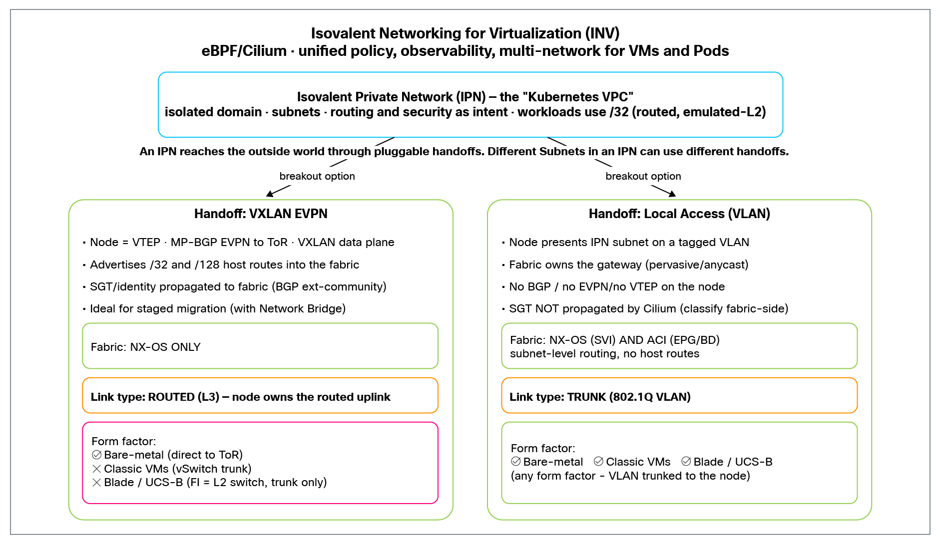
Isovalent Networking for Virtualization – Architecture overview
Current focus: VM workloads
As mentioned in the introduction, INV is currently targeted at VM workloads. VMs map naturally onto the IPN model, as they expect stable, externally visible IP addresses and behave like traditional hosts on a network. Note that users typically never connect to the pod IP directly, as these are abstracted through a service IP address representing one or multiple pods. For traditional workloads such as VMs, a deterministic IP address is often expected.
INV builds on top of an already-working Kubernetes/OpenShift cluster with Isovalent Networking for Kubernetes as its primary CNI, and it extends a functioning cluster network rather than replacing it. As such, the cluster must be installed and healthy, with basic pod-to-pod connectivity in place, before the IPN handoff can be added. In addition, the chosen handoff (handoff) model imposes requirements on the node form factor and how the nodes attach to the fabric. This section covers both: the working-cluster baseline the integration depends on, and the form-factor/attachment prerequisites for each handoff.
A working Kubernetes cluster with pod-to-pod connectivity
Before any IPN can be configured, as stated earlier, the Kubernetes/OpenShift cluster must already be installed and operational with Isovalent Networking for Kubernetes as its primary CNI.
This baseline pod-to-pod (and node-to-node/control plane) connectivity is carried over a dedicated set of links — not the same links used for the IPN handoff. As described in the East-West section, intra-cluster traffic (pod CIDR, Kube-API, bootstrap, etcd, node to node) rides the cluster plane (e.g., bond0), while the IPN handoff — VXLAN EVPN or VLAN — uses the separate handoff plane (e.g., bond1). Keeping these planes physically distinct is a deliberate part of the design: it allows the cluster to bootstrap and operate independently of the handoff and lets the sizing and troubleshooting of each path occur on its own.
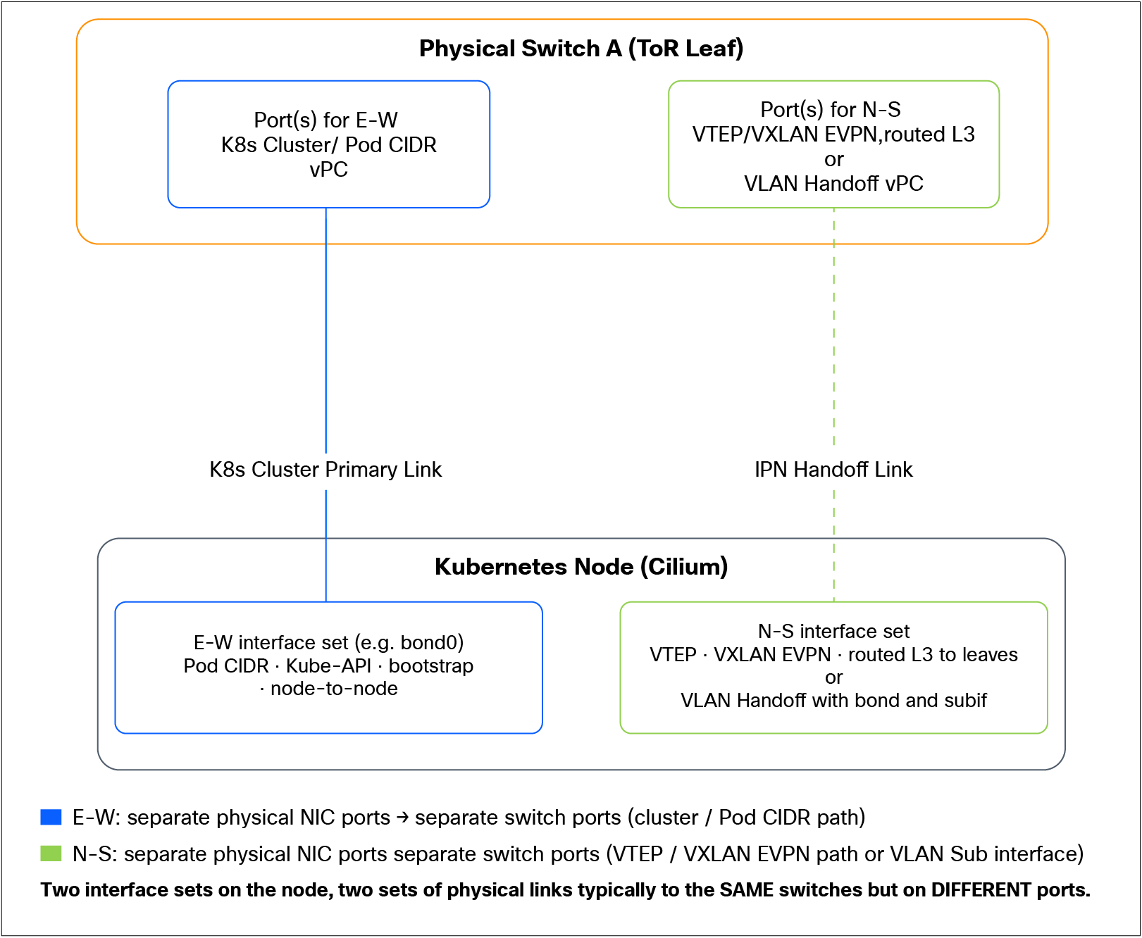
Two traffic classes → Two interface sets → Two sets of physical links
Configuring the cluster pod-to-pod network
The cluster network can be implemented in several ways, and the choice is largely independent of the IPN handoff design. The two common options are:
● Auto direct node routes with VXLAN encapsulation disabled (recommended): In this design we recommend running Cilium with auto direct node routes and no VXLAN/overlay encapsulation for the pod CIDR. Pod-to-pod traffic is then routed natively between nodes (with the underlying fabric/node-subnet routing — or interfabric routing across sites — providing node reachability). This keeps the cluster data path simple, avoids encapsulation overhead, and makes troubleshooting straightforward.
● VXLAN encapsulation for the cluster network (supported alternative): If the environment requires it — for example, where direct routing of the pod CIDR between nodes is not feasible — Cilium can instead use VXLAN encapsulation for pod-to-pod traffic. This is fully supported; it simply means the cluster plane uses an overlay rather than direct routing.
Note: The encapsulation choice here applies only to the cluster (pod-to-pod) network and is independent of the IPN handoff. It should not be confused with the VXLAN EVPN handoff, which is a separate overlay (VXLAN tunnel endpoint VTEP to VTEP toward the leaves) used exclusively for north-south/inter-IPN traffic.
Kubernetes nodes form factor
The choice of handoff model has a direct impact on what compute form factors the Kubernetes worker nodes can run on. This is driven by how each model connects to the fabric — specifically, whether the node-to-fabric link must be a routed (Layer 3) interface or can be a Layer 2 trunk. This section summarizes the form-factor implications of each handoff.
VXLAN EVPN handoff
The VXLAN EVPN handoff requires the node-to-leaf links to be routed (Layer 3) interfaces — the node is a VTEP that sources VXLAN and peers with the leaves over routed links. This requirement significantly constrains the supported form factors:
● Bare-metal nodes, directly attached to the Top-of-Rack (ToR) switches (the supported model): Because NX-OS devices currently support VXLAN encapsulation/decapsulation only for traffic sent and received via routed Layer 3 interfaces, the practical and recommended deployment is bare-metal Kubernetes nodes connected directly to the ToR leaf switches using point-to-point Layer 3 links.
● Classic VMs are NOT supported: A Kubernetes node running as a standard VM cannot present a routed (Layer 3) uplink to the fabric, which — as noted in the previous point — is a hard requirement for this mode. A VM's connectivity is delivered through the hypervisor's virtual switching, which is VLAN/trunk-based, so the node has no way to expose the routed point-to-point interface that the VXLAN EVPN handoff depends on. As a result, virtualized Kubernetes nodes cannot be used with this model. (Technically, PCI passthrough — passing a physical NIC directly through to the VM — could provide a routed interface, but doing so largely defeats the purpose of virtualizing the node in the first place, so it is not a meaningful deployment model here).
● Blade chassis (e.g., Cisco UCS® B-Series) are not supported: In a blade architecture the Fabric Interconnect (FI) presents itself to the upstream fabric as a switch and requires trunk interfaces toward the fabric. This is fundamentally incompatible with the routed Layer 3 uplink that VXLAN EVPN requires, so blade-chassis form factors cannot be used for the EVPN handoff.
Summary (EVPN): The routed-Layer 3 requirement effectively mandates bare-metal nodes directly connected to the ToR. Classic VMs and blade-chassis (trunk-based) form factors are not supported.
Local Access (VLAN) handoff
The Local Access handoff is far more flexible, because the node connects to the fabric over a Layer 2 trunk rather than a routed interface — and a trunked VLAN can be delivered to virtually any compute form factor:
● Bare-metal nodes: Supported.
● VMs: Supported; the required IPN VLAN(s) simply need to be trunked to the worker VM's interface through the hypervisor's virtual switching.
● Blade servers (e.g., UCS B-Series): Supported; the trunk-based, switchlike behavior of the FI is exactly what this model expects.
In short, any form factor works with the VLAN handoff.
A note on virtualized Kubernetes nodes: The VLAN model supports running Kubernetes workers as VMs, including on blade chassis, and there are valid use cases for doing so — for example, nested OpenShift environments. However, when those workers host VM workloads, the resulting nested virtualization adds complexity and potential performance overhead. This is a supported architecture, but it requires careful design and a clear understanding of the operational trade-offs. For general-purpose VM-hosting clusters, bare-metal workers remain the preferred option.
Table 1. Summary of form factors and supported handoffs
| Form factor |
VXLAN EVPN handoff (routed Layer 3) |
VLAN/Local Access handoff (trunk) |
| Bare metal, direct to ToR |
✓ Supported (recommended) |
✓ Supported |
| Classic VM (hypervisor vSwitch) |
Χ Not supported* |
✓ Supported (VLAN trunked to VM) |
| Blade chassis (e.g., UCS B / FI) |
Χ Not supported (FI requires trunks) |
✓ Supported |
Isovalent Private Networks: The Kubernetes VPC
IPN is the foundation of the INV feature set: a VPC-style networking construct built natively inside Kubernetes. The operational model will be familiar to anyone who has worked with cloud VPCs: each IPN is an isolated network domain with its own subnets and address spaces, routing policy, and security perimeter.
VMs are placed into an IPN by intent: the administrator declares which network and subnet a workload belongs to, and the control plane handles connectivity. Routing and security within an IPN are likewise expressed as intent: you define what the network is and what it is permitted to do, and INV translates that into eBPF programs enforced at the kernel level on each node.
IPN handoff and external connectivity options
External connectivity from an IPN is provided through a set of pluggable access options that map to how the underlying network is built:
● VXLAN EVPN: Standards-based Layer 3 reachability to the fabric using BGP EVPN Layer 3 VNIs, enabling the cluster to participate in an existing data center routing domain without static routes.
● Local Access (VLAN) (Layer 3): 802.1Q tagged ingress/egress, supported as a distributed function across all or some worker nodes in a cluster.
Multi-NIC support for VMs
INV supports multi-NIC attachment for VMs and pods directly into IPNs using a Multus wrapper, leveraging standard Network Attachment Definitions (NADs). A VM can attach to multiple IPNs simultaneously, each with its own routing policy and security context.
Single-interface VMs are equally supported. Multi-NIC is an option, not a requirement — a VM can just as well be configured with a single interface placed in one IPN. This is the common case for typical VM workloads that need to participate in only one network/tenant, and it works exactly the same way as a multi-NIC VM, simply with one attachment instead of several.
Unlike the common pattern of pairing Multus with a secondary CNI (bridge/MACVLAN) that operates outside the primary policy model — leaving the second interface without visibility or enforcement—INV applies the full treatment to every interface: eBPF-enforced policy, Timescape observability, and integration with the IPN routing domain. All interfaces can be mapped independently to build arbitrary topologies with no observability blind spots.
IPN IP to pod IP mapping
Within an IPN, each VM is assigned both an IPN IP (the externally visible address) and an underlying pod IP (from the pod CIDR). The Cilium data plane maintains a dynamic mapping between the two, transparently translating traffic addressed to the IPN IP onto the corresponding pod IP. Workloads remain unaware of the translation. Cilium also installs implicit policy ensuring that VMs/pods part of different IPNs cannot communicate directly.
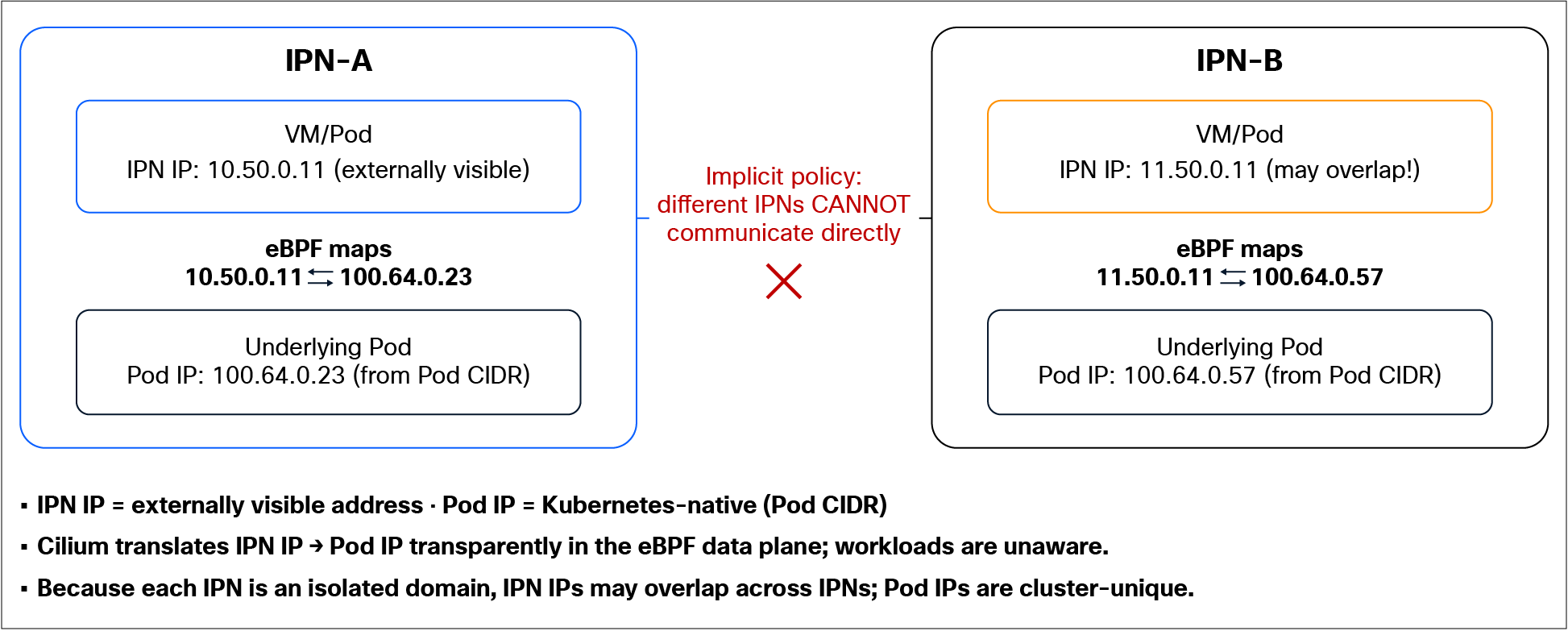
IPN IP ↔ pod IP mapping
Workloads are always routed
It is important to understand a principle that is common to both VXLAN EVPN and Local Access (VLAN) modes: Regardless of which handoff you choose, VM workloads in a Private Network are always configured with /32 host addresses (/128 for IPv6), and their traffic is always routed — never bridged.
In both modes:
● Each workload is assigned a /32 host address, not a conventional subnet mask onto a shared Layer 2 segment.
● The workload's default gateway is the Cilium anycast IP (e.g., 169.254.0.1 for IPv4).
● In Local Access mode, Cilium acts as a router that emulates Layer 2 toward the workload: every packet is received at the anycast gateway and forwarded based on a routing decision, rather than being bridged across a broadcast domain.
● In VXLAN EVPN mode, Cilium acts solely as router.
A direct consequence is that workloads that appear to share the same subnet/VLAN are not actually Layer 2-adjacent — traffic between them is routed by Cilium, and there is no common Layer 2 broadcast domain. This is the same model in both handoff modes and has the same implications (for example, solutions that depend on true Layer 2 behavior are not supported).
What differs between the two modes is only what happens after Cilium has routed the packet — i.e., how the traffic is handed off to the fabric:
● Local Access (VLAN): The routed packet is placed onto a tagged VLAN, and the fabric (ACI bridge domain or NX-OS Switch Virtual Interface [SVI]) provides the gateway and routing.
● VXLAN EVPN: The packet is VXLAN-encapsulated, VTEP to VTEP, toward the leaf, which routes it in the appropriate tenant VRF.
In other words, the workload-facing behavior is identical in both modes (routed /32, anycast gateway, emulated Layer 2 for VLAN mode); only the fabric-facing data path changes.
The detailed routing behavior, the packet walks for each mode, and the implications of the routed /32 model are covered in the sections that follow.
Intra-IPN east-west vs. inter-IPN north-south forwarding
The two traffic classes use two different physical paths
A key architectural point is that intra-IPN east-west traffic and north-south inter-IPN traffic do not use the same physical links on the node. They are carried over two distinct bond/interface sets, because they operate on two different IP planes.
Table 2. IP planes used by the two traffic classes
| Traffic class |
IP plane used |
Physical path on the node |
| Intra-IPN east-west (same IPN) |
Pod CIDR (pod to pod) |
Cluster/Kube-API interface(s) — the same links used to bootstrap the nodes |
| North-south inter-IPN (leaves the IPN) |
IPN IP → IPN handoff* |
Dedicated interfaces used for IPN handoff |
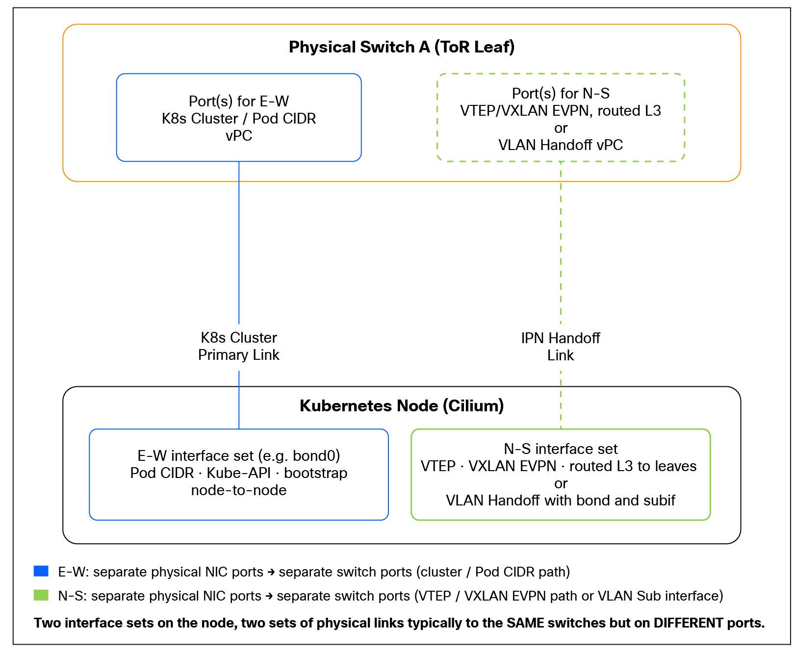
Two traffic classes → Two interface sets → Two sets of physical links
Why this separation matters
● Different links, different sizing: East-west (pod CIDR) bandwidth lands on the cluster/Kube-API links, while north-south lands on the VTEP/EVPN links. Each should be sized and monitored independently.
● Fault isolation: A problem on the EVPN/VTEP path does not break intra-IPN east-west traffic (and vice versa), since they are physically and logically distinct.
As established earlier, the Cilium data plane maps each VM's IPN IP onto an underlying pod IP from the pod CIDR. When two workloads in the same IPN communicate, Cilium resolves the destination IPN IP to its pod IP and forwards the traffic as ordinary pod-to-pod traffic in the pod CIDR.
The consequence is that intra-IPN east-west traffic uses the node's primary data path— the same physical links (typically bond0, carrying Kube-API, node-to-node and pod-to-pod traffic). In other words, since this is pod-to-pod traffic, it shares the cluster networking links and does not use the IPN handoff interfaces at all.
Intra-IPN east-west is plain pod networking on the cluster links — the same plane the nodes already use to come up. In this scenario, pod-to-pod communication follows the way the communication is set up for the cluster, leveraging either VXLAN encapsulation between nodes or native routing/bridging via the network fabric. Refer to the “Pod network and routing (the prerequisite cluster network)” section for more details. The recommended option is native routing, as it provides better visibility and does not result in double encapsulation in the fabric (VXLAN in VXLAN).
North-south traffic carried over the IPN handoff
Traffic that leaves the IPN (this includes inter-IPN traffic even on the same Kubernetes node) is considered north-south traffic. This traffic is handled on a separate IPN handoff data path. Any flow whose destination is outside the IPN must be sent to the fabric for routing, because the IPN is a self-contained routing and security domain and cannot resolve external destinations on its own.
Examples of this north-south case are:
● External services communicating to an endpoint within an IPN (inbound).
● Endpoints in the IPN communicating to any external service (outbound).
● Inter-IPN communication: A single cluster can host multiple IPNs side by side, but they are isolated from one another by design — workloads in different IPNs cannot communicate directly within the cluster. For two IPNs to talk, their traffic must leave the cluster via the handoff and be routed through the fabric (as described in the next section), making inter-IPN communication a north-south flow rather than a local one.
The mechanics of how this traffic reaches the fabric depend on the handoff mode configured for the IPN:
● VXLAN EVPN mode: The traffic is VXLAN-encapsulated VTEP to VTEP over the node's routed Layer 3/VTEP interface and routed by the leaves (and the EVPN-terminating NX-OS devices). The workload's IPN IP is reachable in the fabric via the EVPN host route (/32 or/128) advertised for it, and return traffic follows the same overlay back to the node.
● Local Access (VLAN) mode: The traffic egresses on the node's tagged VLAN interface toward the fabric, where the fabric's pervasive/anycast gateway (ACI bridge domain or NX-OS SVI) performs the Layer 3 routing.
In both cases the principle is the same: the IPN handoff is the egress path out of the IPN, and it is the only path north-south traffic takes.
This behavior is built into the design: intra-IPN east-west traffic is efficiently forwarded as pod-to-pod traffic over the cluster’s pod CIDR links, while traffic leaving the IPN follows the designated handoff path.
Inter-IPN communication: Routing via the fabric
Different IPNs are isolated network and security domains, and Cilium installs an implicit deny that prevents workloads in different IPNs from communicating directly inside the cluster — even when the source and destination VMs happen to be running on the same node.
Instead, the traffic must exit the IPN boundary and be routed by the fabric: the source IPN forwards the packet up to the fabric (① in the figure), the fabric routes and enforces policy on it, and the return path delivers it back down into the destination IPN (②). Once the traffic leaves the cluster, it becomes a classic inter-VRF routing-and-policy scenario, which can be handled and influenced by VRF route leaking or steered through an external service device such as a firewall.
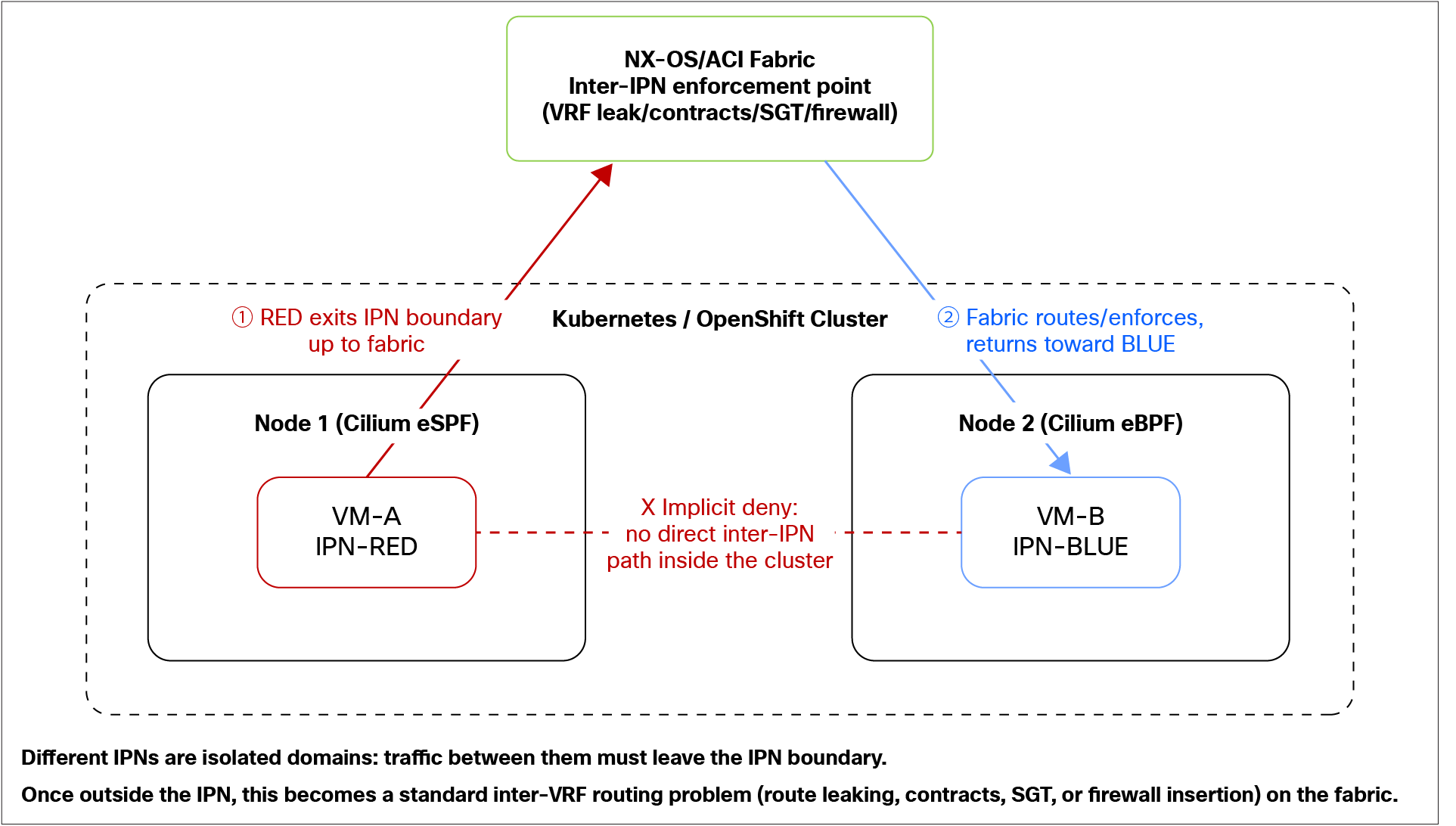
Inter-IPN communication must hairpin through the fabric
This makes the fabric the natural, deliberate enforcement point for inter-IPN communication, in contrast to intra-IPN east-west traffic, which bypasses the fabric entirely. Note that intra-IPN traffic can still be restricted through Isovalent network policies.
Tip: Isovalent Network Policies (INP) are a Cilium-specific Kubernetes Custom Resource (CRD) for defining network security rules. They extend the standard Kubernetes network policy with richer, identity-aware capabilities — including Layer 3/4 and Layer 7 (application layer) filtering (e.g., HTTP, gRPC, DNS), label/identity-based rather than IP-based selectors, and support for cluster-wide policies. Enforcement happens in the Linux kernel via eBPF, and because policy is tied to workload identity (labels) rather than IP addresses, it follows workloads as they are rescheduled or migrated.
Architecture and deployment guidelines
This chapter provides detailed architecture and deployment guidance for integrating an IPN with a Cisco fabric. As established earlier, an IPN reaches the fabric through one of two handoff models — VXLAN EVPN or Local Access (VLAN) — and the right choice shapes much of the design that follows.
In VXLAN EVPN mode, the cluster participates natively in the fabric's routing domain: each node is a VTEP that peers with the leaves over Multiprotocol BGP (MP-BGP) EVPN and advertises per-host routes (/32 or /128) directly into the fabric. This unlocks the capabilities Local Access cannot provide — host-route granularity, Security Group Tag (SGT)/identity propagation as a BGP extended community, and progressive host-by-host migration (especially when paired with the network bridge). The cost of this capability is greater complexity (a full EVPN design: BGP, next-hop manipulation, multipath, Bidirectional Forwarding Detection [BFD]), support on NX-OS only (ACI cannot terminate EVPN from the nodes yet), and a stricter form-factor requirement (routed Layer 3 links, effectively meaning bare-metal nodes directly attached to the ToR).
In Local Access (VLAN) mode, the cluster does very little toward the fabric: the IPN subnet is presented on a tagged VLAN and the fabric owns the Layer 3 gateway (an ACI bridge domain or NX-OS SVI), using its normal pervasive/anycast gateway. There is no BGP, no EVPN, and no VTEP on the node. This makes it the simplest model, supported on both NX-OS and ACI, and compatible with any node form factor (bare metal, VMs, blades) because the attachment is just a VLAN trunk. The trade-offs are that connectivity is subnet level (the fabric routes the whole IPN subnet, not individual workloads), identity/SGT is not propagated to the fabric by Cilium, and there is no per-host route attraction — which limits its suitability for staged migrations.
Table 3. Comparison of clustering in the two handoff modes
| Local Access (VLAN) |
VXLAN EVPN |
|
| Fabric support |
NX-OS and ACI |
NX-OS only |
| Gateway/routing |
Fabric owns the gateway (bridge domain/SVI) |
Distributed; cluster advertises into the fabric |
| Route granularity |
Subnet level |
Per host /32 or /128 |
| Identity to fabric |
Not propagated (classify fabric-side) |
SGT via BGP extended community |
| Node form factor |
Any (bare metal, VM, blade) |
Bare metal, routed Layer 3 to ToR |
| Migration fit |
Greenfield subnets |
Staged, host-by-host (with network bridge) |
| Relative complexity |
Low — "nothing fancy" |
Higher — full EVPN design |
This section describes the architecture for integrating an IPN with a Cisco NX-OS fabric using the VXLAN EVPN handoff. This architecture makes VM workloads in an IPN natively reachable within the data center routing domain — using a standards-based BGP EVPN control plane and a VXLAN data plane — without static routes.
Before we describe the individual building blocks, it is important to understand the architectural model underpinning the VXLAN EVPN integration.
Peer with the ToR switches — A scale-out model
The design is built around peering each Cilium node directly with its ToR leaf switches, rather than tunneling VXLAN and BGP EVPN through to a small number of centralized aggregation or border devices. Every node establishes its underlay BGP and overlay MP-BGP EVPN sessions with the two leaves it is physically attached to, and acts as a software VTEP.
Note: In the figure below, the spines are configured as Border Gateway spines.
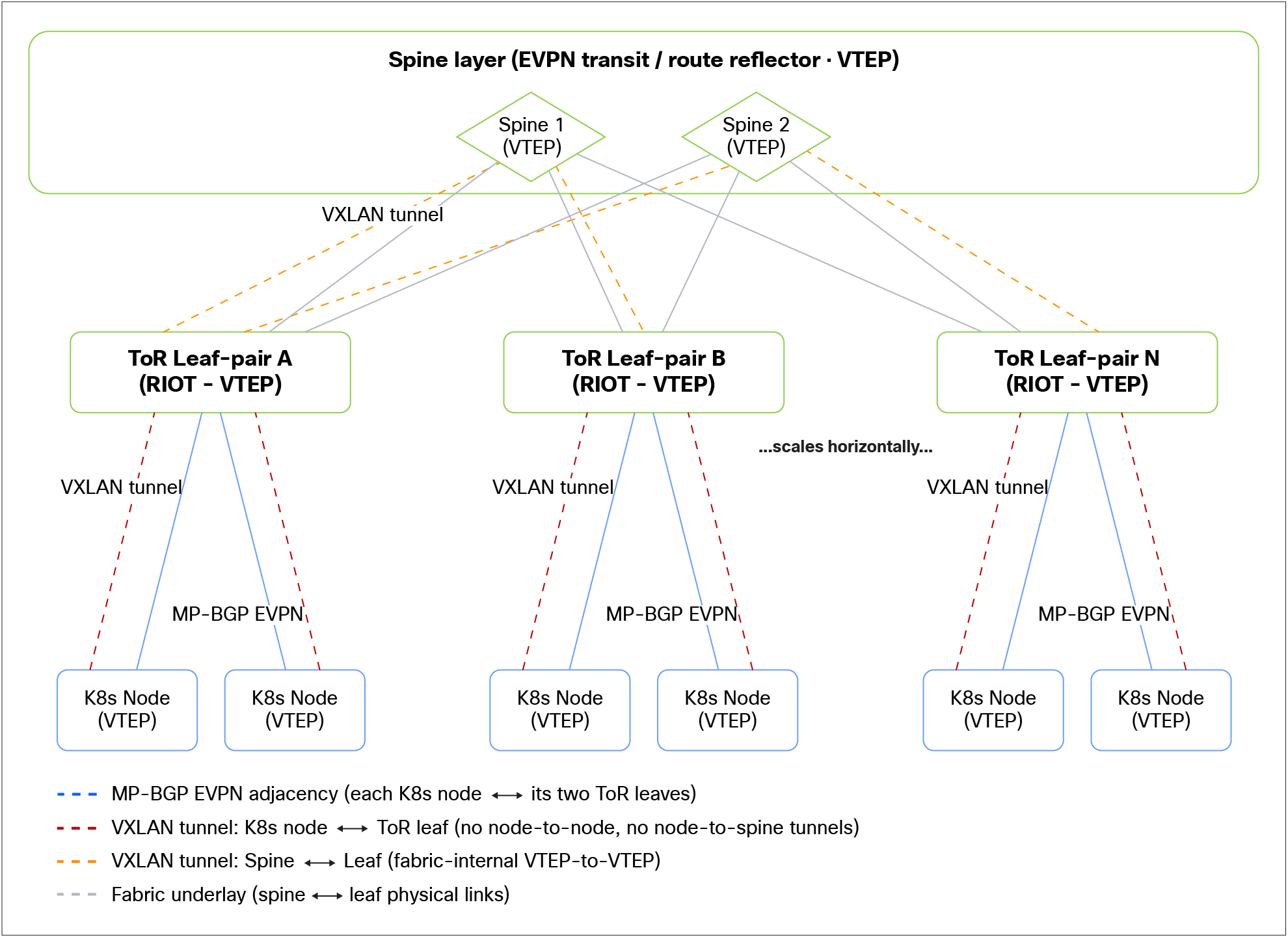
Scale-out model: Distributed peering at the ToR (with NX-OS RIOT)
This is a deliberately distributed scale-out model, and it is the key to scaling the integration:
● Horizontal scaling: Capacity grows by adding nodes and the leaves they attach to; there is no central choke point that can become a bottleneck for EVPN traffic or peering.
● Locality and fault isolation: Because peering is anchored at the local ToR switches, EVPN sessions, VTEP state, and traffic stay local to the rack/leaf pair. A problem at a local TOR pair will remain an isolated problem.
● Even load distribution: EVPN session load, VTEP entries, and tunnels are spread across all participating leaf switches, rather than concentrated on a few devices — which helps scale both the clusters to larger node counts and the fabric to a higher number of switches.
● Deterministic and bounded forwarding state: Combined with the next-hop manipulation described later, the distributed model terminates the per-node tunnels into the ToR leaves, so the rest of the fabric never builds tunnels directly to individual nodes. A generic leaf simply sees an IPN host route as reachable via the two ToR leaves the node connects to — i.e., over two VXLAN tunnels, each destined to the primary IP address (PIP) of one of those two ToR leaves — rather than over a separate tunnel to every node. At the same time, the VXLAN tunnel originated from the Cilium node to allow communication between a locally hosted VM and a fabric’s (or external) resource is also terminated on one of the local leaf nodes, which would then decapsulate the traffic, perform the Layer 3 lookup, and reencapsulate toward a remote fabric’s leaf. This keeps the fabric-wide tunnel and VTEP state bounded and predictable as the node count grows.
In short, distributed peering at the ToR is what allows the integration to scale out to large clusters, rather than being limited by the capacity of a centralized termination point.
Leveraging NX-OS RIOT
To terminate the VXLAN EVPN tunnels from the Cilium nodes and route to the rest of the fabric, the design leverages the Routing In and Out of Tunnels (RIOT) capability of NX-OS leaf switches. RIOT is what allows the leaf to route traffic into and out of VXLAN tunnels in hardware — decapsulating overlay traffic, performing the Layer 3 lookup in the appropriate tenant VRF, and reencapsulating as needed.
By relying on RIOT on the ToR leaves, the design keeps the VXLAN routing function distributed at the same scale-out tier where the nodes peer, consistent with the ToR peering model above, rather than hairpinning overlay-to-underlay routing through a separate centralized set of devices.
At a high level, the following will be built:
● Routed (Layer 3) node-to-leaf connectivity with a BGP unnumbered underlay that advertises the VTEP and loopback addresses needed for the overlay (See INV prerequisites section).
● An MP-BGP EVPN overlay session between loopback interfaces defined on the Cilium nodes and on the leaf switches where the node is connected, over which the node advertises and receives routes and, optionally, workload identity (SGT).
● A VRF-to-VNI mapping that imports each IPN's routes into the correct tenant VRF on the fabric, preserving multitenant isolation from end to end.
● ToR leaves next-hop manipulation in two directions — toward the nodes (consistent leaf PIP for VXLAN encapsulation) and toward the spines (to prevent a per-node tunnel explosion) — using route-map policies.
● Fast failure detection for the overlay session using Multihop BFD.
● EVPN add path so that traffic toward a dual-homed workload is load-shared across both leaf switches.
● Optional outbound (egress) load sharing across both uplinks, using the Kubernetes node's Layer 4 multipath hashing combined with the per-flow variation of the VXLAN outer source port, to spread egress flows evenly across both node-to-leaf links at per-flow granularity.
Goal of the node-to-leaf connection
The purpose of the physical connection between the Cilium nodes and the ToR leaf switches is twofold:
● Establish the MP-BGP EVPN overlay sessions between the Cilium nodes and the leaf switches.
● Forward VXLAN data plane traffic between the Cilium node VTEP and the VTEP of the ToR leaf switches the nodes connect to.
In other words, the underlay must simply provide IP reachability between the node's VTEP/loopback and the leaf's VTEP/loopback, so that:
● The overlay MP-BGP EVPN session can be established between those loopbacks, and
● VXLAN-encapsulated traffic can be exchanged between the two VTEPs.
The single strict requirement for the node-facing port is that it is a routed (Layer 3) interface. Beyond that, how reachability between the VTEPs/loopbacks is achieved over that Layer 3 link is an implementation choice, and several options exist, as described in the following section.
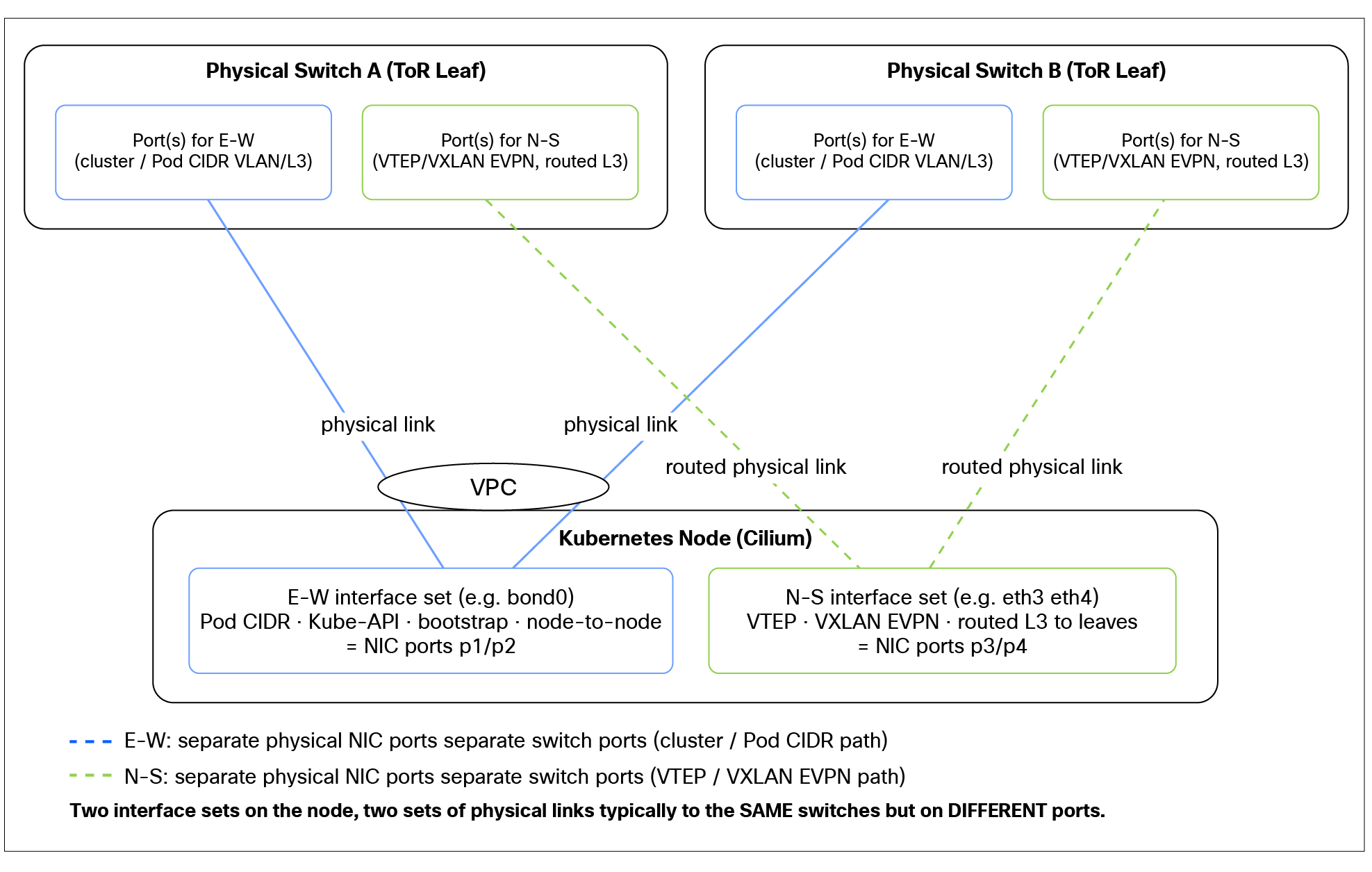
E-W vs N-S Interface requirements
Options for establishing reachability
Recommended approach: BGP Unnumbered for the underlay
The recommended approach is to run BGP Unnumbered on the routed node-to-leaf links to establish a BGP underlay session. This underlay session is used to advertise the routing and VTEP loopback address ranges that the MP-BGP (overlay) EVPN session is then sourced from and used as VXLAN tunnel endpoints.
The advantages are:
● No per-link persistent IPv4 or IPv6 addressing: Eliminates the need to plan, allocate, and track an address per link.
● No static route maintenance: The VTEP/loopback reachability is learned dynamically.
● Scales cleanly: Adding a node is largely a templated, repeatable operation, regardless of the number of nodes/links.
Conceptually:
● Underlay (BGP Unnumbered): Advertises the node's loopback/VTEP into the fabric, and the leaf's VTEP/routing loopbacks down to the node, giving both ends the routes needed to reach each other's VTEP and establish the MP-BGP L2VPN/EVPN session.
● Overlay (MP-BGP L2VPN/EVPN): Sourced from those loopbacks, carries the EVPN routes; VXLAN traffic flows from VTEP to VTEP using the reachability information exchanged via EVPN.
IPv6 requirement and IPv4 over IPv6 (RFC 5549)
BGP Unnumbered relies on IPv6 link-local peering, so it works only with IPv6 on the link:
● If the VTEPs are IPv6, this maps directly: The underlay establishes IPv6 reachability between the IPv6 VTEPs/loopbacks.
● If the VTEPs are IPv4, BGP Unnumbered can still be used by leveraging RFC 5549 advertising IPv4 Network Layer Reachability Information (NLRI) over the IPv6 link-local BGP session. This provides IPv4 VTEP/loopback reachability while still benefiting from the unnumbered, addressing-free underlay.
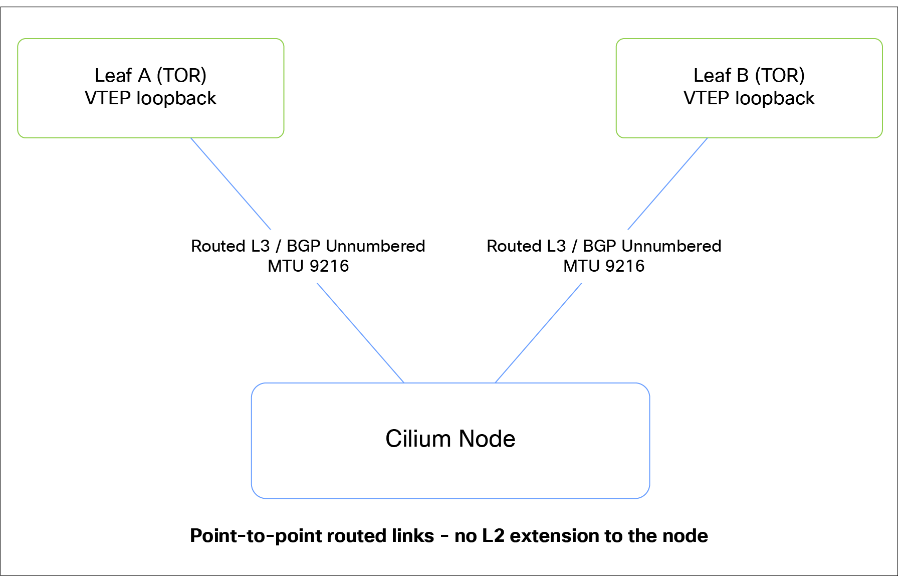
Node-to-fabric physical connectivity using dual routed point-to-point links to two ToR leaves
Manually addressed links and static routes or BGP (works, but cumbersome at scale)
The point-to-point Layer 3 links between a node and the two ToR leaf switches can have manually assigned IP addresses. Reachability between the node VTEP/loopback and the leaf VTEP/loopback can be provided with static routes on both ends or BGP. This is perfectly valid for a handful of nodes, but it scales poorly: every node addition, removal, or readdress requires manual route maintenance on both the nodes and the leaves. In a deployment of any meaningful size this quickly becomes an operational burden and a source of error.
Routing behavior in VXLAN EVPN mode
The workloads in an IPN are configured with /32 host addresses (and /128 for IPv6), and their default gateway is the Cilium anycast IP (e.g., 169.254.0.1 for IPv4). Cilium acts as a router toward the workload — it receives every packet at the anycast gateway and makes a routing decision.
Even though workloads in an IPN appear to share a subnet, there is no common Layer 2 broadcast domain between them. Each workload talks only to its anycast gateway, and Cilium routes the traffic — so traffic between two workloads is routed, never bridged even within the same IPN subnet.
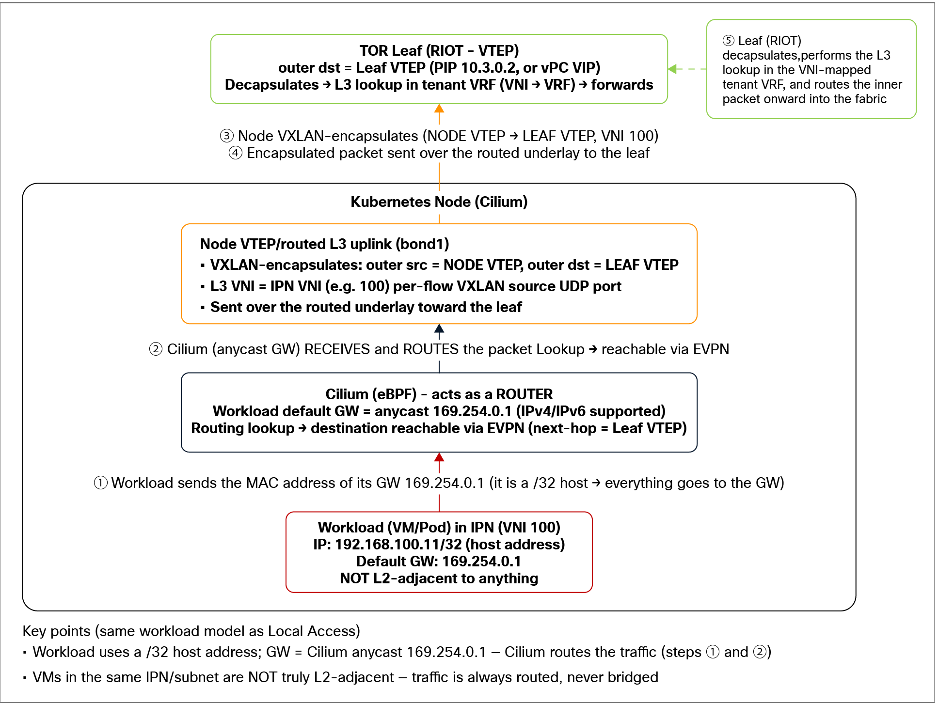
VXLAN EVPN packet walk
Note: Currently Cilium will not import EVPN routes whose AS path already contains its own ASN, and allowas-in is not supported. This matters because all Cilium nodes in the cluster typically share the same ASN: a route that originates from one IPN, exits to the fabric, and is then advertised back toward the cluster will carry the Cilium ASN in its AS path—and the receiving Cilium node will therefore drop it on import. As a result, any inter-IPN communication that relies on routes being learned back from the fabric (the hairpin path, where two IPNs talk via the fabric) must be designed with this limitation in mind. When planning inter-IPN connectivity, ensure that the return path does not depend on Cilium reimporting a route that still carries its own ASN—for example, by handling the inter-IPN routing entirely on the fabric side so the cluster is not required to relearn its own-origin prefixes.
L3VNI without VLAN for NX-OS VXLAN EVPN
NX-OS supports a newer Layer 3 VNI deployment model referred to as L3VNI without VLAN. In this mode, the VRF’s L3VNI is no longer dependent on a dedicated local VLAN association. This simplifies the configuration and removes several operational dependencies associated with the traditional VLAN-backed L3VNI model.
L3VNI without VLAN is the recommended best practice for newly created VRFs. It is particularly relevant to the next-hop manipulation described in this document because it removes the requirement to configure the Router MAC (RMAC) explicitly in the route maps used for next-hop manipulation.
Nexus Dashboard configuration
L3VNI without VLAN is not currently the default for Nexus Dashboard-managed fabrics. It must be enabled using:
Fabric Settings → Fabric Management → Advanced → Enable L3VNI w/o VLAN
Once enabled, Nexus Dashboard applies the new model only to VRFs created after the setting is enabled. Existing VRFs are not automatically converted.
Existing VRFs and migration considerations
Migrating an existing VRF from a VLAN-backed L3VNI to an L3VNI without VLAN is outside the scope of this document. The migration requires a separate operational procedure and may affect traffic forwarding while the configuration is changed.
Existing VRFs should therefore remain in their current mode unless a planned migration is performed.
Legacy L3VNI mode
For a preexisting VRF that uses the legacy VLAN-backed L3VNI model, the overall configuration described in this document remains unchanged, with one additional requirement: the route maps used for next-hop manipulation must explicitly set the RMAC.
Traffic may appear to forward correctly without the RMAC being configured, but this configuration is unsupported and is not guaranteed across all platforms, releases, or forwarding scenarios. The RMAC must therefore be configured explicitly for legacy VRFs.
In summary:
● Use L3VNI without VLAN for newly created VRFs.
● RMAC configuration in the next-hop route maps is not required for VRFs using the new mode.
● Existing VLAN-backed L3VNIs require the RMAC to be set explicitly.
● Migration of existing VRFs must be treated as a separate, traffic-impacting procedure.
VRF-to-VNI mapping
Each IPN is configured with a specific EVPN L3VNI that identifies its tenant routing domain. On the NX-OS device, a corresponding VRF can be configured with the same L3VNI to simplify the exchange of EVPN prefixes. This common L3VNI value is the anchor that ties the IPN overlay domain to the fabric tenant VRF, and it is what makes multitenant route separation work end to end.
How route import works (Auto-RT default behavior)
Both the fabric (NX-OS) and Cilium are configured to auto-generate the Route Distinguisher (RD) and Route Targets (RT), rather than having them assigned by hand (the latter is a supported option, when desired).
Auto-generation of RDs and RTs use the encoding formats from RFC 4364 Section 4.2:
● The RD uses Type 1 encoding, such as 10.0.0.1:1. The administrative field is the router ID, and the numbering field is the internal VRF ID.
● Import and export RTs use Type 0 encoding, such as 65000:100. The first (administrative) field is the local Autonomous System Number (ASN), and the second (numbering) field is the L3VNI of the IPN (on Cilium) of the VRF (in the fabric).
Matching export and import RT values is the mechanism that allows control over the exchange of prefixes between EVPN neighbors for a given routed domain. As mentioned earlier, auto-derived import/export RTs include the ASN and the L3VNI value (ASN:VNI format).
The recommendation is to match the L3VNI values assigned to the IPN and to the fabric’s VRF, as keeping a consistent value from end to end simplifies operation. However, since the fabric and Cilium use different ASNs, EVPN prefixes advertised by a Cilium node carry an RT that the fabric leaf’s VRF does not import, and vice versa.
This issue is solved in a different way on the fabric’s leaf and on the Cilium node:
On the fabric’s leaf: A rewrite-evpn-rt-asn option is associated to the Cilium’s EVPN neighborship, to rewrite the ASN portion of the RT value associated to the received EVPN prefixes to match the fabric’s ASN. The result is the automatic import of those received prefixes in the fabric’s VRF.
On the Cilium node: For eBGP peers, Cilium compares only the VNI part, assuming the remote peer also uses Type 0 encoding with the L3VNI in the numbering field. So keeping the L3VNI value consistent between the Cilium node and the fabric is all that is needed to be able to successfully import the EVPN prefixes advertised by the fabric’s leaf.
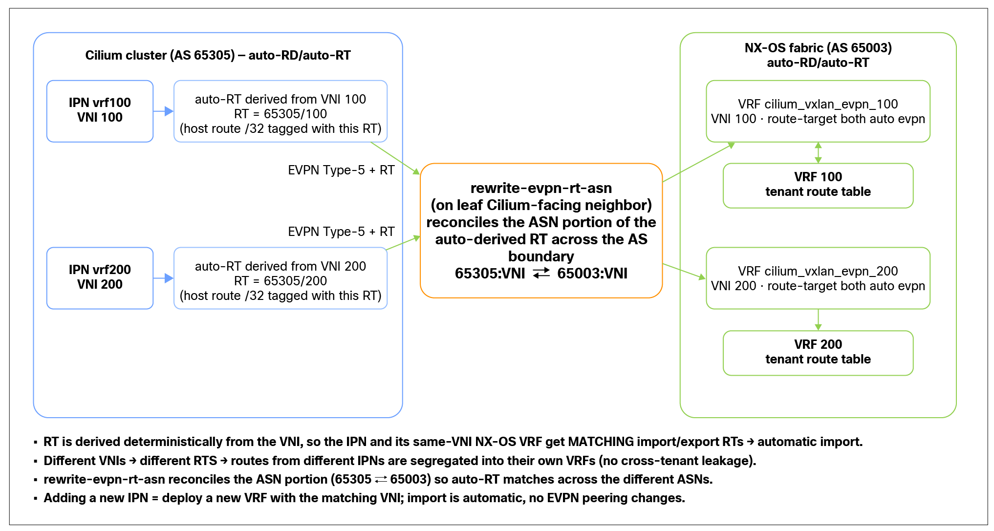
Node-originated host routes imported into the correct tenant VRF on NX-OS
What this mapping guarantees
● Each advertised VM host route carries the L3VNI of its IPN, so its RT identifies the tenant it belongs to.
● Auto-RD/auto-RT keeps configuration simple and consistent at scale — RDs and RTs are computed from the L3VNI/ASN rather than hand-assigned, so there is nothing per route or per tenant to maintain manually.
● Routes from different IPNs are segregated into their respective VRFs, because each VRF imports only the RT matching its own L3VNI — there is no cross-tenant leakage.
● Adding a new IPN requires only deploying a new VRF (with the matching L3VNI) in the fabric — the L3VNI-derived RT values make import automatic, so no change to the EVPN peering configuration is needed.
Workload-to-SGT mapping based on Kubernetes labels
Overview
Beyond placing each workload's routes into the correct tenant VRF, the integration can (optionally) propagate workload identity into the fabric so that group-based policy can be applied. In the VXLAN EVPN model, this is achieved by mapping workloads to Security Group Tags (SGTs) and carrying that classification to the fabric as a BGP extended community alongside the EVPN host routes.
The classification is driven by Kubernetes labels. We derive the SGT from the labels already attached to the VM/pod, the same metadata that operators and application teams use to describe their workloads (e.g., environment, tier, tenant, application). This keeps identity definition where it belongs: with the workload, expressed as intent.
How it works
● A workload carries one or more Kubernetes labels (for example app=payments, tier=db, env=prod).
● A policy maps a set of labels to a specific SGT value.
● When Cilium advertises that workload's EVPN Type 5 /32 (or /128) host route, it attaches the corresponding SGT as a BGP extended community.
● The fabric receives the route, learns both the reachability and the group/identity of the endpoint, and can enforce group-based policy on traffic to and from that workload — without any per-IP fabric classification.
This means an endpoint's security group is tied to the workload itself, not to its location in the fabric. As VMs/pods are created, rescheduled, or live-migrated, what changes, from the fabric's perspective, is where the workload's IP appears. The workload's labels, and therefore its SGT, remain unchanged: the same identity is re-advertised alongside the relocated host route, and the fabric updates the endpoint's location automatically through the EVPN control plane while continuing to apply the same group-based policy. In short, the IP may move around the fabric, but its security group stays constant.
Managing SGT values between environments
When mapping workloads to SGTs (whether via the defaultGroupID in the CiliumConfig or per workload via FabricSecurityGroup), the operator is manually choosing the numeric SGT values that Cilium will propagate to the fabric.
It is the operator's responsibility to ensure that the SGT values chosen for IPN workloads do not overlap with any security group identifier already in use elsewhere in the data center fabric. Because the SGT is a flat 16-bit numeric identifier that the fabric uses directly for group-based policy, an overlap would cause the fabric to merge Cilium-originated workloads with unrelated endpoints that happen to share the same SGT value — leading to unintended policy being applied (traffic permitted or denied incorrectly) and to ambiguous, hard-to-troubleshoot enforcement behavior.
To avoid problems, the operator should:
● Maintain a fabric-wide SGT allocation registry. Track which SGT ranges are already used for classification, other integrations, and existing group-based policy, and treat IPN/Cilium SGTs as just another consumer of that shared space.
● (Optionally) reserve a dedicated SGT range for IPN/Cilium-originated workloads, agreed upon with the fabric/security team, so cluster-side allocations cannot collide with fabric-side ones.
● Review allocations as part of change control whenever new IPNs, new FabricSecurityGroup objects, or new fabric-side groups are introduced, since there is currently no automatic guard against overlap.
Why label-based mapping matters
● Identity expressed as intent: Segmentation is defined by what a workload is (its labels), not by where it happens to land (its IP/subnet). This aligns the fabric policy with the same model used inside the cluster.
● Dynamic and self-maintaining: There is no manual fabric step to classify new endpoints; adding a labeled workload automatically results in the correct SGT being advertised. The only fabric-side prerequisite is that the corresponding SGT must exist in the fabric configuration with an ID that matches the value set in the cluster. Beyond defining that SGT and its associated group-based policy, no classification rules need to be created on the fabric — there is no need to map IPs, ports, subnets, or Endpoint Groups (EPGs) to the group. The fabric simply trusts the classification that Kubernetes provides: Cilium derives the SGT from the workload's labels and carries it in the EVPN route as a BGP extended community, and the fabric applies policy based on that received value. This means new endpoints are classified entirely from their Kubernetes labels, with the fabric only ever needing the matching SGT/policy definition to be in place — never a per-endpoint classifier.
◦ Note: Currently, Cilium can classify workloads and propagate their SGT to the fabric (derived from Kubernetes labels and carried as a BGP extended community), but it does not yet use SGTs to enforce policy itself. In other words, the SGT is exported for the fabric to act on (group-based policy), while in-cluster enforcement continues to rely on Cilium/Kubernetes network policies, not SGTs. Likewise, any SGTs received from the fabric are currently ignored by Cilium — they are not used to make policy decisions inside the cluster. SGT-based enforcement is therefore effectively one-directional: Cilium provides identity to the fabric but does not consume SGT identity for its own policy.
● Consistent end-to-end posture: The same labels can drive both Cilium's in-cluster network policy and the fabric's SGT-based policy, giving a coherent security model across the cluster boundary.
● Scales cleanly: This is particularly important in environments with large, churn-heavy estates, where maintaining IP-to-group mappings by hand on the fabric would be impractical.
Note: This capability is specific to the VXLAN EVPN integration and is not available in the VLAN handoff option.
Next-hop manipulation
This section assumes that the fabric has been deployed with Cisco Nexus® Dashboard using the default "Data Center VXLAN EVPN iBGP" fabric template with Internal BGP (iBGP) as the overlay (i.e., the standard iBGP EVPN design where the leaves peer to the spines acting as route reflectors). The next-hop behavior, route-map placement, and AS-based scoping described below are written against this default Nexus Dashboard iBGP EVPN model.
Two distinct next-hop problems must be solved with route-map policy.
Toward the nodes
When advertising EVPN routes to the Cilium nodes, the leaves must explicitly rewrite the next hop to a single, consistent local VTEP address. This is required because the next hop NX-OS would otherwise advertise is not consistent across all cases. For routes a leaf originates locally, NX-OS correctly uses its own VTEP IP as the next hop. However, for routes the leaf re-advertises rather than originates — for example, a host route learned from a peer leaf and then advertised onward to the Cilium node over the External BGP (eBGP) EVPN session — the EVPN/VXLAN next-hop logic does not apply, and the default behavior is to use the local BGP session IP (the leaf's routing loopback) as the next hop, rather than the VTEP.
If the Cilium node received that routing loopback as next hop, it would not have a valid VTEP to encapsulate VXLAN traffic toward. To make the behavior deterministic regardless of whether a given route is locally originated or re-advertised, we apply an outbound route map toward the Cilium node that explicitly sets the next hop to the local VTEP IP. This guarantees that the node always receives a single, predictable VTEP next hop, independent of how the leaf learned the route.
The next-hop value the route map sets toward Cilium depends on how the leaves are connected — whether they form a virtual port channel (vPC) pair or are kept as independent Layer 3 switches:
● Pure Layer 3 → Set the next hop to each leaf's own PIP — a different IP per leaf. The node sees two distinct VTEP next hops; the control plane and inbound traffic work correctly, but egress is pinned to a single link (Cilium currently does not support equal-cost multipath [ECMP] routing).
● vPC pair → Set the next hop to the vPC anycast VTEP (virtual IP [VIP]) — the same IP shared by both leaves. The node sees a single, stable VTEP reachable over two equal-cost underlay paths, which (combined with the node's Layer 4 multipath hashing) enables egress load balancing across both links.
How egress load balancing works in the vPC case involves the combination of the shared anycast VTEP and the node's Layer 4 multipath hashing:
● Because both leaves present the same vPC anycast VTEP, the node has a single, stable VTEP next hop to encapsulate toward, while the underlay still offers two equal-cost paths (one to each leaf) to reach that anycast VTEP.
● With net.ipv4/ipv6.fib_multipath_hash_policy = 1 on the node and the per-flow variation of the VXLAN outer source port, the kernel spreads the encapsulated flows evenly across both uplinks toward the two leaves, giving good, per-flow egress load sharing. Note: The uplinks remain routed Layer 3 links and are not configured in a vPC.
In other words, in the vPC case the anycast next hop gives the node a consistent VTEP to encapsulate to, and the two equal-cost underlay paths to that VTEP — combined with the varying VXLAN source port per flow — are what deliver outbound load balancing across both links. In the pure Layer 3 case, the per-leaf PIP is used instead, with egress limited to a single link.
Refer to the “Outbound (egress) traffic load balancing” section for more details.
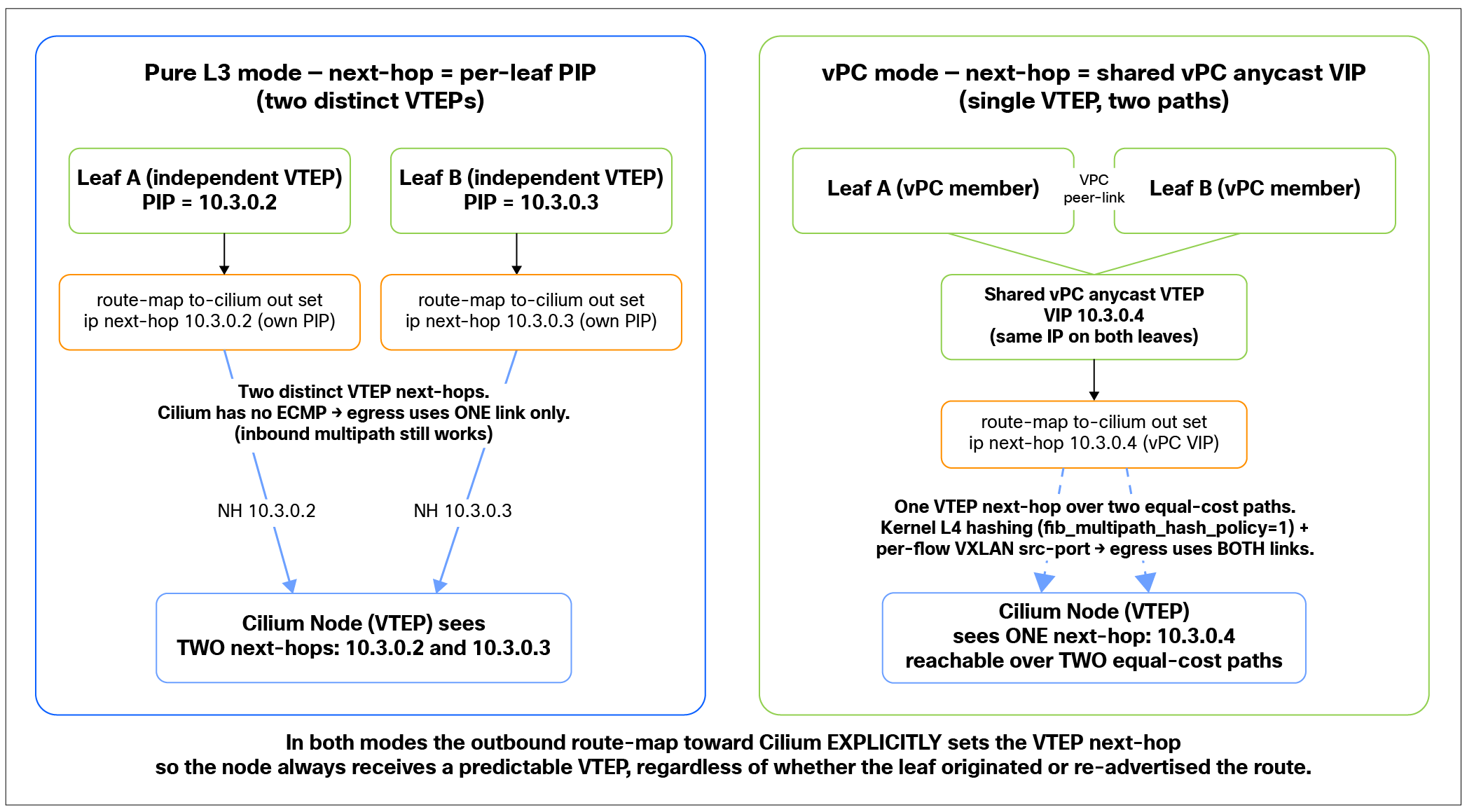
Next-hop rewrite toward the nodes (Pure Layer 3 vs. vPC)
Toward the spines
When leaves re-advertise EVPN routes learned from the nodes up to the spines (the fabric’s route reflectors), the next hop defaults to the Cilium node's loopback. This is the expected behavior for eBGP-to-iBGP redistribution (this assumes you are using iBGP as the underlay). Left unchanged, every other leaf would build a VXLAN tunnel directly to every node: a tunnel explosion. To prevent this, leaves must rewrite the next hop of node-originated routes to their own PIP (using the PIP is required to ensure that node-side link failures do not result in traffic being sent to a leaf with no active path toward the node), collapsing N tunnels per leaf pair into two.
This rewrite must be scoped only to node-originated routes. One way to achieve this is by matching on the AS path of the node’s neighbors; however, any other option that achieves the goal is also valid.
| ip as-path access-list k8s-vxlan seq 1 permit "^65305$" ip as-path access-list k8s-vxlan seq 2 permit "^65302$"
route-map to-spines-cilium-set-next-hop permit 10 match as-path k8s-vxlan set ip next-hop 10.3.0.3 ! leaf PIP
route-map to-spines-cilium-set-next-hop permit 30 |
● Sequence 30 (permit, no match) ensures that all other fabric EVPN routes are advertised unchanged — the intent here is explicitly not to alter the default fabric behavior. We want to rewrite the next hop only for node-originated routes; every other EVPN route must pass through exactly as the fabric would normally advertise it.
Caution: Do not use match as-number for this purpose: it only applies to filtering dynamic neighbors and will not work here.
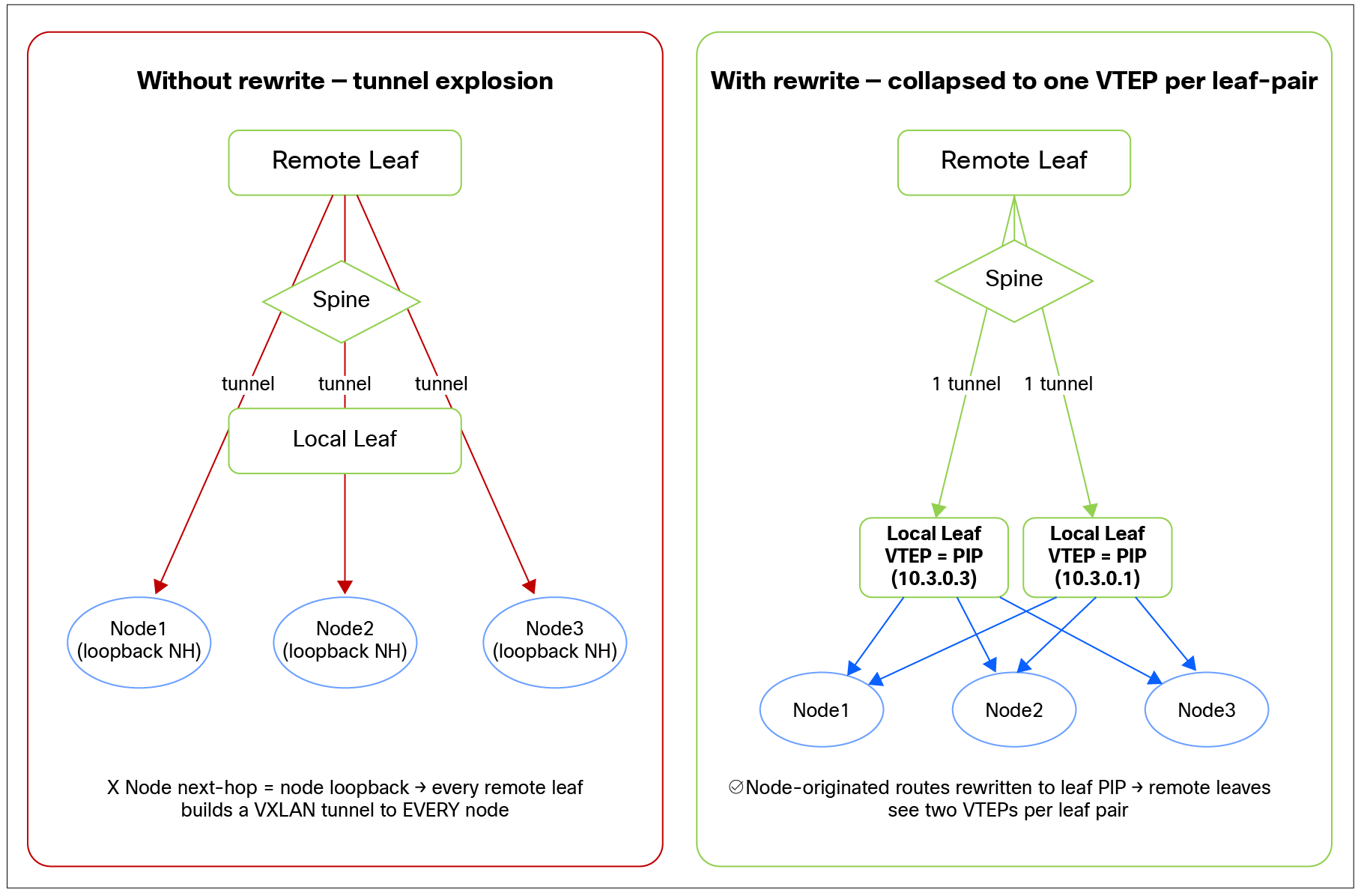
Next-hop rewrite toward spines
Configuring the RMAC for next-hop manipulation for VLAN-backed L3VNI
For legacy VLAN-backed L3VNI deployments, the route maps used for next-hop manipulation must set the appropriate RMAC explicitly.
Obtain the required MAC addresses from the leaf switch using:
| show nve interface nve 1 detail |
Use the values reported in the output as follows:
● PIP next hop: Use the local router MAC.
● VIP next hop: Use the virtual router MAC.
Configure the corresponding value in the route map that performs the next-hop manipulation. This step is not required for VRFs using L3VNI without VLAN.
Example configuration:
| route-map to-cilium-set-next-hop-vpc permit 10 match evpn route-type 5 set ip next-hop <PIP/VIP> set extcommunity evpn rmac <RMAC/vRMAC> |
EVPN add path for inbound traffic load sharing
In this design, a given VM prefix is dual-homed: each Cilium node connects to two leaves, so the same EVPN host route (/32 or /128) for the VM’s IP address is advertised into the fabric from both leaves. For inbound traffic (originated from a fabric’s or external resource and destined to the VM) to be load-balanced across all available paths rather than collapsed onto a single best path, the other leaf nodes in the fabric must be able to install multiple ECMP next hops for the same EVPN prefix.
As explained in a previous section, a route map is provisioned on each leaf node to ensure that the next hop associated to the VM’s IP prefix injected into the fabric is rewritten to each specific leaf’s PIP address. This ensures that two separate PIP addresses are advertised as next hop to reach the same VM resource. However, the Route Distinguisher (RD) associated to the VM’s prefix remains unmodified as the RD of the Cilium nodes hosting the VM. The consequence is that the route-reflector nodes (the fabric’s spines) would receive the same EVPN prefix (RD+host prefix) from both leaf nodes. By default, the BGP process on the route reflectors would select and advertise only the single best path per prefix, which would hide the existence of the two redundant paths from the rest of the fabric and waste the available capacity and redundancy. To expose and install all valid paths, the design enables EVPN Additional Paths for both the spines and the leaves.
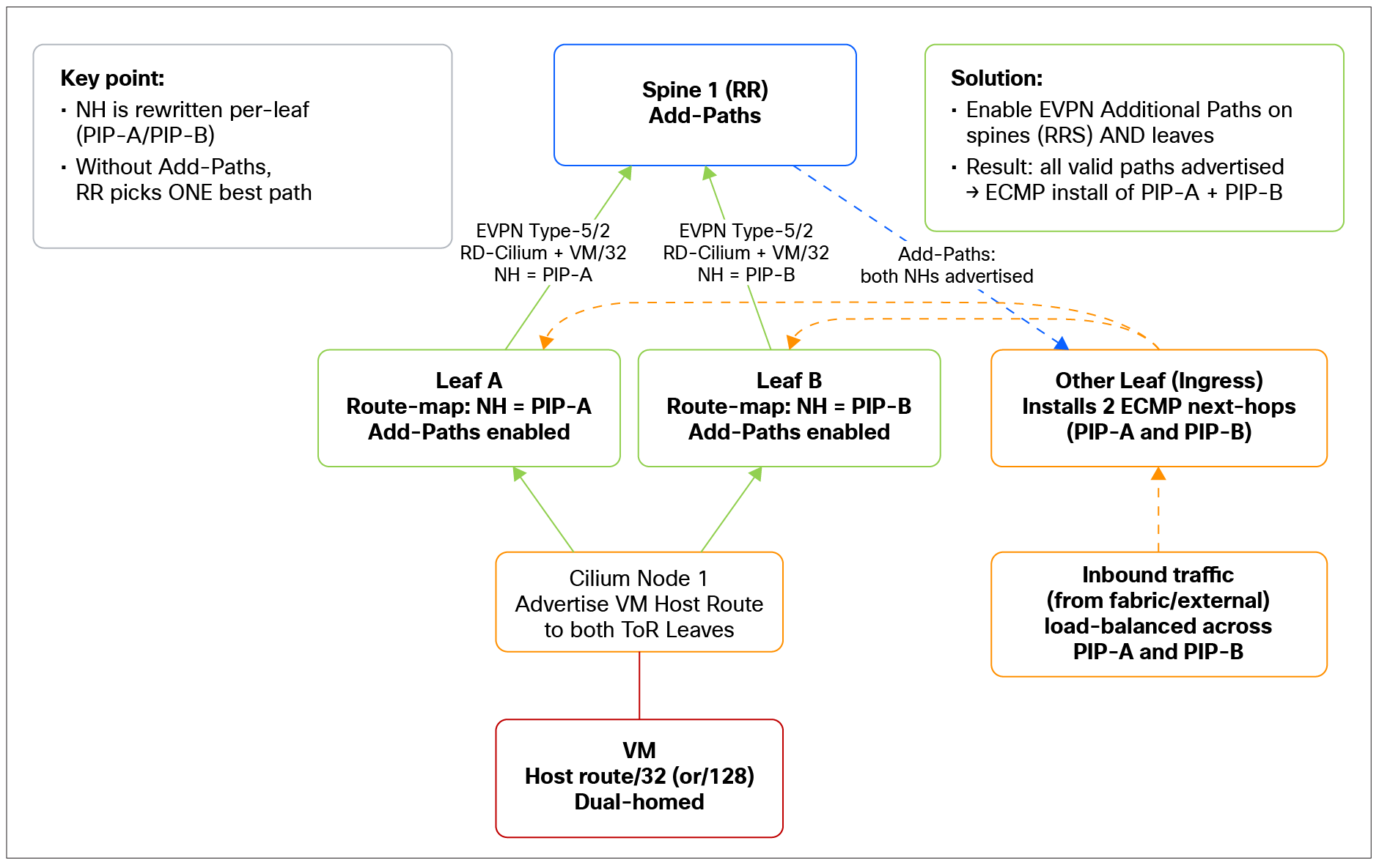
ECMP via PIP next-hop rewrite + additional paths
This delivers:
● Multipath/ECMP forwarding: Traffic to a dual-homed workload is spread across both advertising leaves, rather than being pinned to one.
● Full use of the redundant topology: Both node-to-leaf links (and both leaves) actively carry traffic; however, EVPN multipath improves load sharing for traffic entering the node/IPN; outbound traffic load sharing is a separate, node-side concern (as discussed in the next section).
● Faster, less disruptive failover: Alternate next hops are already installed, so the loss of one path does not require a best-path recomputation before traffic can use the remaining path(s).
Outbound (egress) traffic load balancing
Leaves: Pure Layer 3 vs vPC pair
How the two leaves present themselves to the node — as two independent Layer 3 VTEPs or as a single vPC anycast VTEP—is a key design decision, and it comes down to whether you need to use both node-to-leaf paths in the egress direction.
Option A: Pure Layer 3 (independent PIP next hops)
The leaves are kept as pure Layer 3, with no vPC between them. In this model each leaf advertises its own PIP (loopback/VTEP) as the next hop toward the Cilium node, so the node sees two distinct VTEP next hops — one per leaf.
This is a perfectly valid design that works fine for the control plane and for inbound traffic. The limitation is on egress: because Cilium does not currently support ECMP, the node cannot load-balance across the two distinct next hops and will therefore use only one of the two links in the egress direction. Inbound traffic (originated from a fabric’s or external resource and destined to a VM) still benefits from EVPN multipath toward the node; it is specifically the outbound direction that is pinned to a single link in this design.
You should configure a routed (Layer 3) link between the leaf pair. This protects against the failure case in which a leaf loses all its uplinks to the spines: without an inter-leaf path, a node whose traffic lands on the isolated leaf would be black-holed, since that leaf can no longer reach the rest of the fabric. With a Layer 3 link between the leaves, the isolated leaf can still forward traffic to its peer (which retains spine connectivity), preserving reachability. This link is used only as a last resort path for fabric isolation and will not be used under any other failure scenarios.
Because each leaf advertises its own PIP as a distinct VTEP, next-hop BFD on the MP-BGP session is required to handle a link failure. See the “Fast failure detection: Multihop BFD for the MP-BGP session” section for more details.
Option B: vPC Pair (shared anycast VIP next-hop)
If you need to use both links in the egress direction, configure the two leaves as a vPC pair and advertise the vPC anycast VTEP (VIP) to the Cilium node as the next hop. The node then sees a single, stable VTEP reachable over two equal-cost underlay paths, which— combined with the node's Layer 4 multipath hashing and the per-flow VXLAN source port (described later in the document) — allows egress flows to be spread across both node-to-leaf links.
Beyond enabling egress load balancing, using vPC is a clean solution even for Layer 3-attached nodes, for several practical reasons:
● No traffic black-holing on leaf isolation from spines: If a physical vPC peer link is used, the leaves, if provisioned by the Cisco Nexus Dashboard Fabric Controller, are automatically configured to peer over the peer link with each other. This means that if one leaf becomes isolated from the spines, traffic can still be forwarded via the peer link to the healthy leaf, so a leaf losing its spine uplinks does not result in a traffic black hole for the node attached to it.
● Graceful behavior during software upgrades/reloads: When a vPC member is reloaded (e.g., during an NX-OS upgrade), it will wait for the vPC delay-restore timer before advertising the VIP VTEP to the Cilium node. This ensures that the switch attracts traffic only when it is fully ready to forward, so forwarding is handled cleanly throughout the reload/upgrade window.
● vPC is very likely already in use (see Figure 4. Two traffic classes → Two interface sets → Two sets of physical links): Most ToR designs are already built around vPC, so adopting it here generally aligns with existing operational practice rather than introducing a new construct.
● BFD is not required: See the section “Fast failure detection: Multihop BFD for the MP-BGP session.”
vPC peer-link requirements for VTEP traffic
In an NX-OS VXLAN EVPN deployment, VTEP traffic cannot be routed across a virtual peer link. If the vPC peer link is intended to provide a backup path for VTEP reachability, the switches must use a physical peer link.
The physical peer link must have sufficient capacity and resiliency to carry the redirected VTEP traffic during uplink failure.
Enabling Layer 4 hashing in Linux
Although the vPC anycast (VIP) VTEP is reachable over two equal-cost underlay paths (the Layer 3 interfaces to each leaf), Linux by default uses only IP addresses (source/destination) to perform load balancing, resulting in the traffic being pinned to a single path. To use both uplinks, we therefore need to tune the multipath hashing in the kernel, controlling how it hashes flows across the equal-cost routes toward the leaves.
The recommended approach is to enable multipath hashing on the node using:
| net.ipv4.fib_multipath_hash_policy = 1 net.ipv6.fib_multipath_hash_policy = 1 |
Setting these sysctls to mode 1 selects the Layer 4 (5-tuple) multipath hash policy, so the kernel distributes flows across the available equal-cost next hops (the two leaves) based on the full flow tuple — source/destination IP, protocol, and source/destination ports — rather than on destination IP alone (mode 0). This gives a much finer per-flow distribution across the two uplinks.
Why this approach achieves good balancing
The key reason this approach works well in a VXLAN design involves what happens to the outer User Datagram Protocol (UDP) encapsulation. When the node encapsulates traffic into VXLAN, the outer VXLAN source UDP port is derived per inner flow — it is computed from a hash of the inner packet's headers, so different inner flows produce different VXLAN source ports.
Combined with fib_multipath_hash_policy = 1, this means:
● Each distinct inner flow yields a different outer source port, so the kernel's Layer 4 hash sees genuinely varied tuples and spreads flows statistically evenly across both VTEP next hops/uplinks.
The net result is good, fine-grained egress load sharing across both node-to-leaf links, achieved purely with standard kernel multipath hashing and the inherent per-flow variation of the VXLAN source port.
Fast failure detection: Multihop BFD for the MP-BGP session
Why BFD is needed if the leaves are pure Layer 3
The MP-BGP L2VPN/EVPN overlay session between the Cilium nodes and the leaves is established between loopback addresses, not between the directly connected physical interfaces.
This introduces a failure-detection gap. Because the session is sourced from loopbacks reached over the routed underlay, a physical link going down does not, by itself, bring the MP-BGP session down. The session will tear down only once BGP's own hold timer expires, which is far too slow.
To detect loss of reachability to the remote loopback quickly, the design uses Bidirectional Forwarding Detection (BFD) to monitor the path to the EVPN peer.
The link-failure concern described above applies primarily to situations in which the leaves advertise EVPN prefixes toward the Cilium nodes with their individual PIP address as the next hop.
Why BFD is not needed if the leaves are in a vPC pair
If the leaves are configured as a vPC pair, the next hop advertised to the node is the shared vPC anycast VTEP (VIP), reachable over two equal-cost paths (one to each leaf). In this case, if a physical link (or the leaf) goes down, the Linux kernel simply rebalances the flows onto the remaining uplink to reach the same VIP VTEP — the VTEP next hop itself does not change, so the forwarding is unaffected by the link loss. For this reason, BFD is not strictly required to handle connectivity failure when the leaves are in a vPC pair.
Ingress traffic is protected by the fabric control plane. The PIP advertisement is tied to the reachability of the corresponding Kubernetes node VTEP. If the node or its VTEP becomes unreachable, the leaf PIP advertisement toward the spines is withdrawn, preventing the fabric from continuing to forward traffic toward that leaf.
Multihop BFD
Because the MP-BGP session runs loopback to loopback, Multihop BFD must be used. Multihop BFD tracks reachability to the remote loopback across the routed underlay, regardless of the specific physical link or number of hops in between. This ensures that:
● A failure that breaks reachability to the peer loopback is detected within a subsecond, rather than waiting for the BGP hold timer.
● The MP-BGP EVPN session, and therefore the VXLAN data plane that depends on it, converges away from a failed path promptly.
Important: Do not combine BFD with Graceful Restart
Note: BFD should not be used together with BGP Graceful Restart (GR) on this session.
The two mechanisms have opposing goals. BFD is designed to tear down the session quickly the moment reachability is lost, so the network can reconverge immediately. Graceful Restart is designed to keep the forwarding state in place and preserve the session across a control plane restart, deliberately avoiding a fast teardown. Enabling both leads to conflicting behavior — the fast failure detection that BFD provides is precisely what GR tries to suppress — and undermines the deterministic, fast-convergence behavior this design relies on. Choose BFD for fast failure detection on the EVPN overlay session, and do not enable Graceful Restart alongside it.
Note: In Cilium Graceful Restart is disabled by default.
Why VXLAN EVPN is ideal for staged migrations
The VXLAN EVPN handoff is particularly well suited to phased migrations — the scenario in which workloads are moved from an existing source environment into the cluster gradually, rather than in a single cutover, allowing for much better control and reducing impact to a minimum.
The key enabler is host-route (/32 or /128) advertisement. Because the cluster advertises individual host routes for migrated workloads into the fabric via BGP EVPN — rather than the entire subnet — traffic can be attracted toward the cluster on a per-host basis, exactly as each workload is migrated:
● No subnet-level conflict: EVPN on the cluster’s nodes advertises only the specific /32 or /128 of each migrated workload. The source environment can continue to advertise the coarser subnet prefix for everything not yet moved, while the fabric prefers the more specific host route for whatever has already migrated. The two coexist cleanly throughout the transition.
● Progressive cutover, no hard switch: Each workload's traffic shifts to the cluster the moment its host route is advertised, so the migration proceeds one workload at a time with no disruptive, all-at-once event.
● Clean end state: Once an entire subnet has been migrated, the host routes remain rooted in the IPN, and the source environment's coarser advertisement can be retired— the fabric sees a continuous, consistent routing domain throughout.
Pairing with the Isovalent Network Bridge
This host-route–based cutover becomes a complete network migration machine when paired with the Isovalent Network Bridge (INB). During the migration window, the bridge provides Layer 3–based connectivity and IP address preservation for workloads spanning the source environment and the cluster, while the EVPN host-route advertisements progressively attract traffic toward migrated workloads. As each segment is fully migrated, the bridge for that segment can be cleanly decommissioned, leaving the EVPN advertisements rooted directly in the IPN.
For details on how the INB works (IP preservation, Address Resolution Protocol [ARP] proxy/stateless NAT/overlay encapsulation, and the EVPN cutover flow), see: https://isovalent.com/blog/post/isovalent-private-networks-and-cisco-nexus-one-bgp-evpn-integration-for-the-enterprise-data-center/#the-migration-machine.
Local Access (VLAN) architecture
Overview
The Local Access (VLAN) handoff is the simplest of the IPN external-connectivity options. The IPN subnet is placed onto a VLAN, and the fabric — whether ACI or NX-OS — acts as the default gateway for that subnet, using its standard pervasive (anycast) gateway mechanisms exactly as it would for any other workload. Because this mode is supported by both NX-OS and ACI, it is the common-denominator integration model across the two fabric types.
Node-side provisioning (managed by Cilium)
The provisioning of the VLAN subinterface on the Kubernetes nodes is managed by Cilium via a CRD. From the fabric's perspective, this behaves just like any other hypervisor using a distributed-switch approach: the node presents the IPN subnet on a tagged VLAN, and Cilium handles the creation and lifecycle of the corresponding VLAN subinterface on each node automatically. This keeps the node configuration declarative and consistent at scale.
Local Access: Physical connectivity options
For the Local Access (VLAN) handoff, the Kubernetes worker nodes simply need the required IPN VLAN(s) presented on their handoff interface, with the fabric (ACI or NX-OS) acting as the gateway. There are two main connectivity options, and both apply equally to ACI and NX-OS fabrics. The right choice depends on whether the Kubernetes workers run on bare metal or are themselves virtual machines.
Option 1 — Bare-metal nodes: Classic Layer 2 vPC
When the Kubernetes nodes are physical (bare-metal) servers, their handoff links can be terminated as a classic Layer 2 vPC between a pair of leaves. The nodes can be configured with a bond interface (Layer 2 port channel in Link Aggregation Control Protocol [LACP] mode) that is connected to both leaves via a vPC. The IPN VLAN(s) are carried on that vPC, and the fabric provides the gateway (ACI bridge domain or NX-OS SVI) for the IPN subnet. This is the most direct model and behaves like any standard dual-homed host attachment.
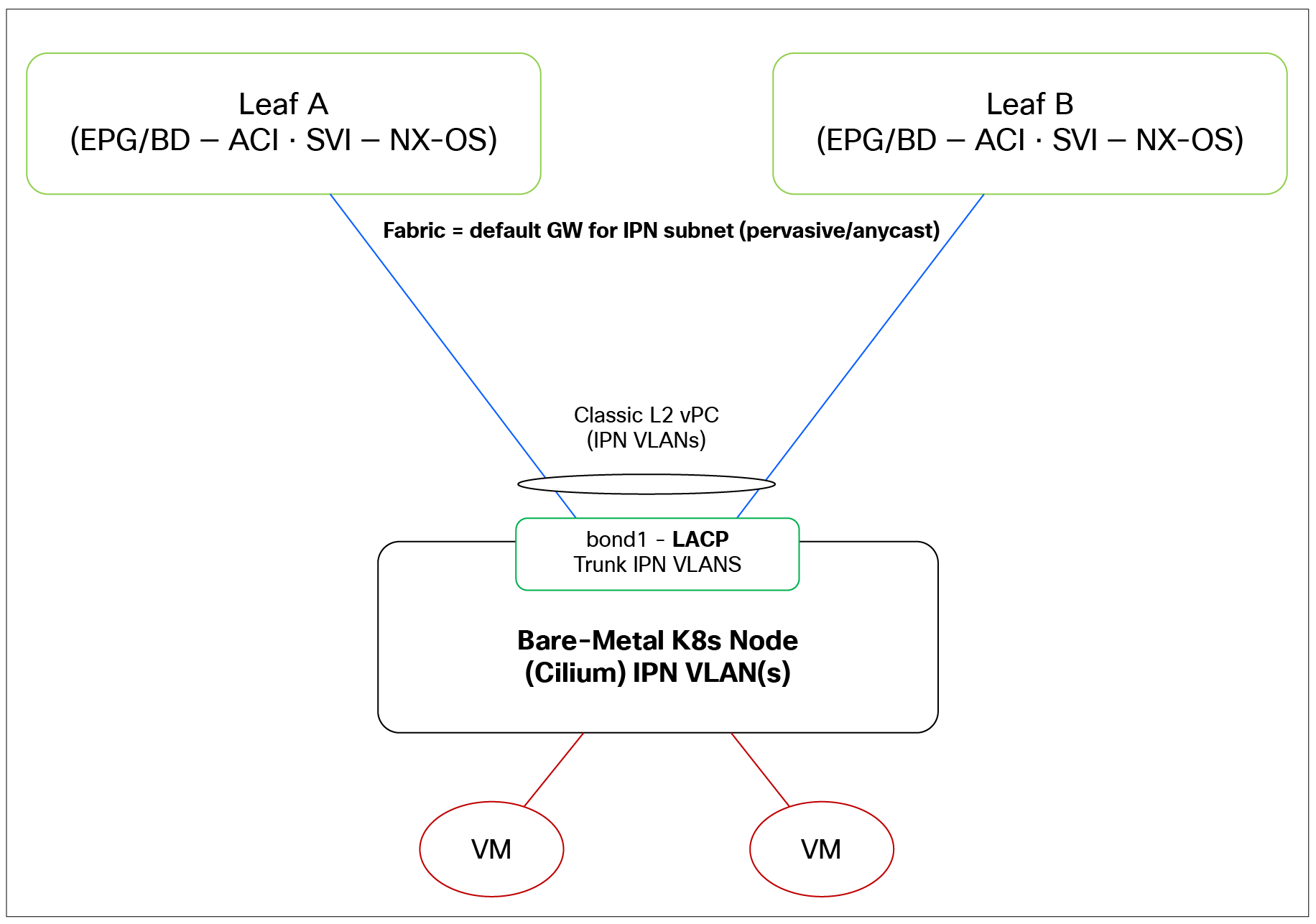
Local Access option 1: Bare-metal worker on a classic Layer 2 vPC
Option 2 — VMs: VLANs trunked through the hypervisor
When the Kubernetes workers are themselves virtual machines (i.e., the cluster runs on top of a hypervisor), Local Access still works — there is no requirement for the Kubernetes nodes to be bare metal. The only requirement is that the IPN VLAN(s) are trunked all the way to the ports used by the virtual Kubernetes nodes for Local Access. In this model:
● The hypervisor host is connected to the fabric, and that host attachment can itself be a vPC to a pair of leaves.
● The required Local Access VLANs are trunked from the leaves, through the hypervisor's virtual switching, to the virtual Kubernetes node handoff interface.
● From the fabric's perspective, the gateway and VLAN handling are unchanged — it still owns the IPN subnet gateway; the VLANs simply traverse an additional virtual switching layer before reaching the VM.
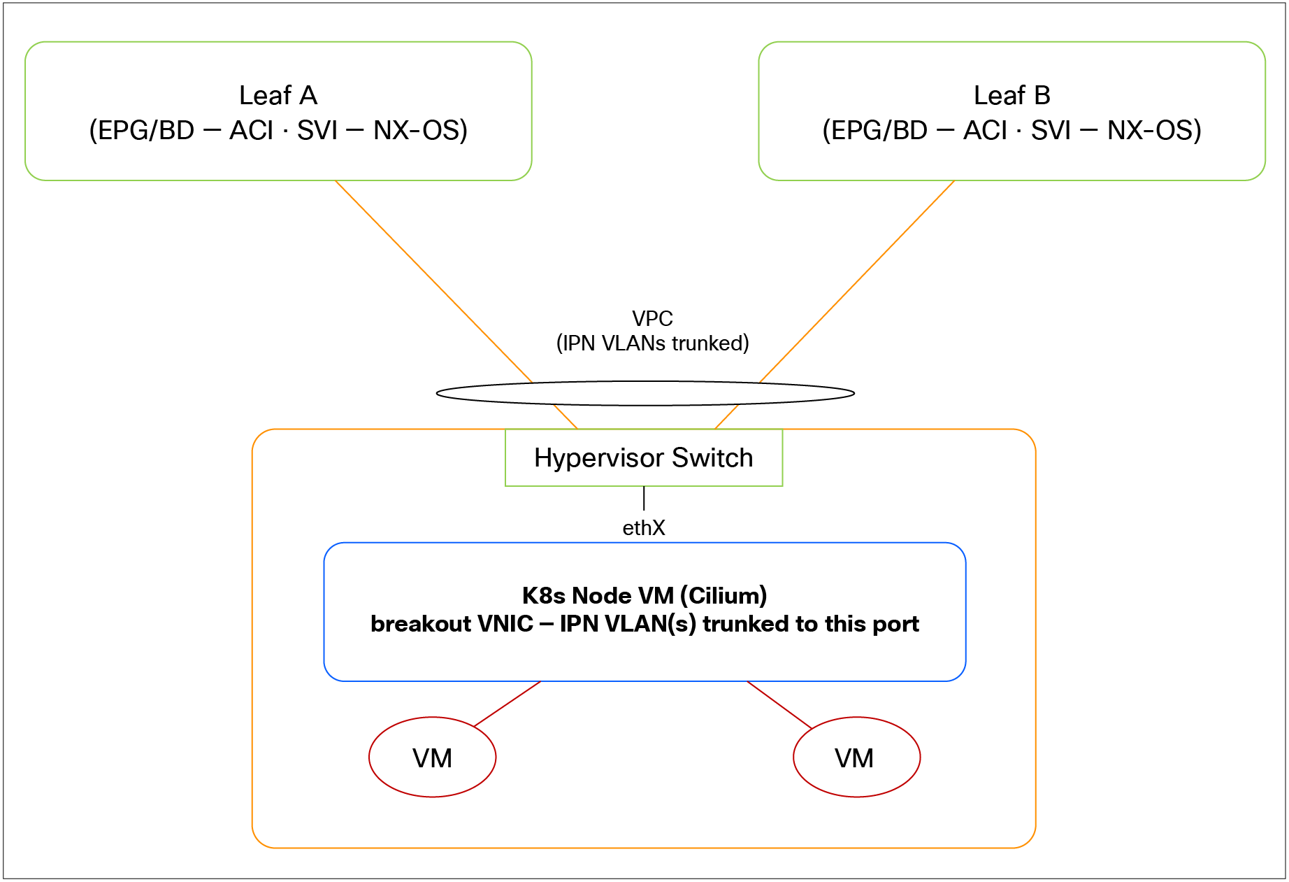
Local Access option 2: Virtualized worker, VLANs trunked via vPC-attached hypervisor
Why Local Access is not a traditional Layer 2 segment
Despite presenting workloads on a VLAN, Local Access is not a true Layer 2 broadcast domain. The implementation is Layer 3-centric:
● VMs are configured with /32 host addresses, not with a conventional subnet mask onto a shared Layer 2 segment.
● The default gateway for the VMs is the Cilium anycast IP, with the fabric providing the subnet's pervasive/anycast gateway upstream.
● Consequently, traffic is routed rather than bridged within the node, even though the workloads appear to sit on a common VLAN.
This distinction matters for any workload or feature that assumes or requires genuine Layer 2 adjacency.
Proxy ARP to the fabric
Because forwarding is Layer 3 based at the node, VMs running on the same Kubernetes node are presented to the fabric as sharing a single MAC address — that of the host node. The fabric therefore sees the node's MAC rather than the individual VM MAC addresses for colocated VMs. This is expected behavior for this mode, but it is another reason Local Access should not be treated as a transparent Layer 2 segment.
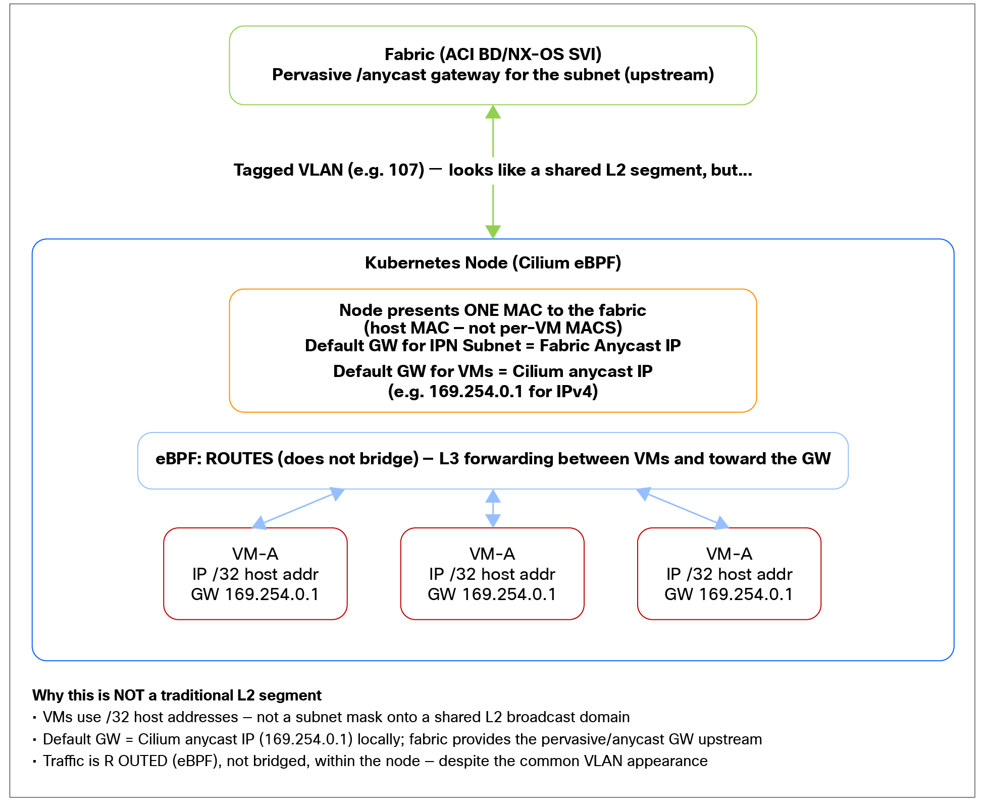
Local Access is Layer 3-centric, not a traditional Layer 2 segment
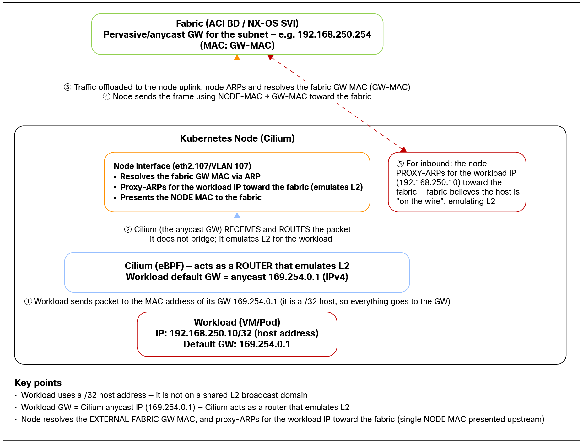
Local Access packet walk
Unsupported: Layer 2-based clustering solutions
Following directly from the two points above, clustering solutions that rely on Layer 2 behavior are not supported in Local Access mode. Anything that depends on true Layer 2 adjacency — for example, broadcast/multicast-based heartbeats, gratuitous ARP-based failover, shared-MAC/floating-MAC schemes, or Layer 2 cluster interconnects between VMs— will not work as it would on a traditional bridged segment.
Unsupported: IPN workloads as VNFs
The VMs are configured with /32 (or /128) host addresses. With a full host mask, the VM has no on-link subnet. Installing a next hop for routing requires the next hop to reside in a directly reachable (on-link) segment. Because the VM's /32 leaves it with no shared subnet, the VM cannot resolve or reach the configured next hop, so the route cannot be installed or used.
Segmentation enforcement: Fabric security groups vs. Kubernetes network policies
Segmentation in this architecture is enforced in two different places, depending on the traffic direction, because the two traffic classes traverse two different data paths. Understanding this split is essential to designing a coherent, end-to-end security posture.
North-south and inter-IPN traffic: Fabric security groups
Traffic that leaves the IPN boundary—both true north-south and inter-IPN flows—exits the cluster via the IPN handoff and is routed by the fabric. Because the fabric sees this traffic, it is the logical enforcement point for it, and segmentation can be applied using the fabric's native security group constructs:
● Cisco ACI: Classification and policy via EPG/endpoint security group (ESG) grouping and contracts.
● Cisco NX-OS: Classification and policy via SGTs and the associated group-based policy.
This means inter-IPN communication (which, due to the implicit inter-IPN deny, must hairpin through the fabric) and any external-facing north-south traffic can be tightly controlled using the same group-based segmentation model already used elsewhere in the data center.
Reminder on identity propagation: In the VXLAN EVPN handoff, workload identity can be derived from Kubernetes labels and carried to the fabric as an SGT in a BGP extended community, so the fabric can classify endpoints automatically. In Local Access (VLAN) mode, Cilium does not propagate the SGT, so the fabric-side classification must be configured locally using the fabric-specific classifiers, i.e., VLAN ID selector, IP address range selectors, etc.
Intra-IPN east-west traffic —Kubernetes network policies
Traffic between workloads within the same IPN (intra-IPN east-west) is handled entirely in the data plane over the pod networking path (the pod CIDR on the cluster links) and does not use the same physical links as the north-south traffic. As a result, the fabric is not an enforcement point for this traffic—fabric security groups (EPG/ESG/SGT) simply never see it.
Segmentation for intra-IPN east-west therefore relies on Kubernetes network policies (and Cilium's eBPF-enforced policy more broadly). These policies are applied within the cluster, follow the workloads as they are scheduled, rescheduled, or live-migrated, and apply consistently to both VMs and pods.
Migration scenarios: An important caveat
While Local Access mode is well suited for fabrics that own a particular subnet, meaning fabric performs routing for that network, it can be problematic in certain scenarios in which an external device advertises the subnet.
In Local Access mode, the fabric must be configured with a bridge domain or SVI for the VM subnet so it can act as that subnet's gateway. If an existing upstream device is already advertising the same subnet into the fabric (for example, a gateway fronting the source environment from which workloads are being migrated), configuring the fabric to also originate that subnet locally creates a routing conflict: the fabric would be presenting the same prefix from two sources. For these scenarios—where the same subnet must be reachable from both the legacy environment and the cluster during a transition—the VXLAN EVPN handoff is the appropriate model, because it advertises per-host /32 or/128 routes that can be attracted toward the cluster progressively, rather than requiring the fabric to own the whole subnet.
Fabric-side configuration
Cisco ACI
On ACI, the node's handoff interface is simply placed into an EPG. The corresponding bridge domain provides the pervasive (anycast) gateway for the IPN subnet, and standard ACI policy (contracts) governs reachability.
Cisco NX-OS
On NX-OS, the fabric provides the gateway for the IPN subnet via an SVI (typically an anycast-gateway SVI in a VXLAN EVPN fabric or a standard/Hot Standby Router Protocol [HSRP] SVI in a more traditional deployment). The VLAN carried on the node's handoff interface is mapped to that SVI, which serves as the default gateway for the subnet.
In both cases the principle is identical: the fabric owns the Layer 3 gateway, and the node presents the IPN subnet on a tagged VLAN whose subinterface is provisioned by Cilium.
This is the configuration for the VXLAN EVPN handoff—the model in which the Cilium nodes become EVPN speakers and VTEPs and integrate natively into the data center routing domain. The goal is to advertise each workload's IP as a host route (/32 or /128) directly into the fabric over a standards-based BGP EVPN control plane, with a VXLAN data plane between the nodes and the leaves.
In practice, we are wiring up three things that work together: the fabric (NX-OS spine + leaves) to terminate and route the overlay, the Cilium control plane to peer with the leaves and originate the EVPN routes, and the IPN itself mapped to a tenant VRF/VNI. The result is a scale-out design where workloads in an IPN are reachable across the fabric, identity can be carried to the fabric as an SGT, and the solution is ready for staged, host-by-host migrations.
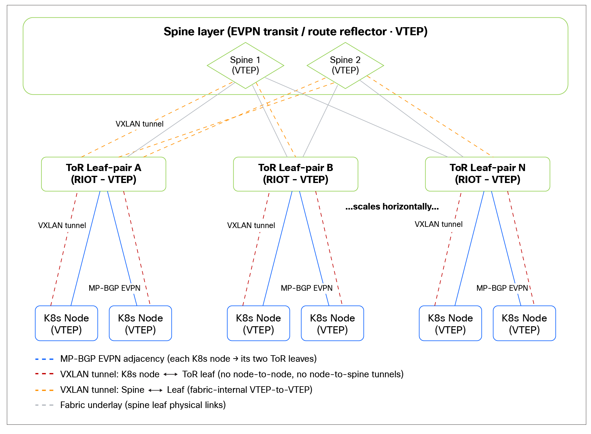
VXLAN EVPN configuration
Fabric-side configuration
Reference configuration: Spine
Overview
The spines in this design act as the EVPN route reflectors/transit layer for the fabric. Their role in the context of the IPN integration is to propagate EVPN routes between leaves and, critically, to advertise multiple paths for the same prefix so that the multipath behavior described earlier actually reaches the rest of the fabric. The spines do not peer with the Cilium nodes directly; they simply need to be configured to send and receive additional paths and to install multiple ECMP next hops in the EVPN Routing Information Base (RIB).
Configuration
| router bgp 65003 router-id 10.2.0.3
address-family ipv4 unicast redistribute direct route-map rmap-redist-direct maximum-paths 64 maximum-paths ibgp 64
address-family ipv6 unicast maximum-paths 64 maximum-paths ibgp 64
address-family l2vpn evpn maximum-paths ibgp 64 additional-paths send additional-paths receive additional-paths selection route-map ADD_PATHS_RM
route-map ADD_PATHS_RM permit 10 set path-selection all advertise |
Explanation of key elements
router bgp 65003 / router-id 10.2.0.3
The spine runs in the fabric BGP AS (65003 in this example) with a unique router ID, typically its routing loopback. This is the same AS used by the leaves for the internal fabric, with the EVPN sessions between leaves and spines being iBGP.
address-family ipv4 unicast and address-family ipv6 unicast
These underlay address families carry the VTEP and loopback reachability that the EVPN overlay depends on (the routes the leaves and nodes need in order to reach each other's VTEPs).
● redistribute direct route-map rmap-redist-direct — Injects directly connected interfaces (e.g., loopbacks/VTEPs) into BGP under the control of a route map, so only the intended prefixes are advertised. (The contents of rmap-redist-direct are environment specific and should be scoped to the loopback/VTEP prefixes you intend to redistribute).
● maximum-paths 64 / maximum-paths ibgp 64 — Allows up to 64 ECMP next hops in the underlay RIB, so the fabric can use all available equal-cost paths for VTEP reachability.
Both IPv4 and IPv6 unicast are enabled to support either VTEP addressing family. If your VTEPs are IPv6, the IPv6 unicast family carries that reachability directly; if they are IPv4 reached over IPv6 (RFC 5549, as discussed in the “Physical connectivity” section), the relevant family carries the corresponding NLRI.
address-family l2vpn evpn
This is the overlay address family, where the EVPN/IPN integration behavior is configured.
● maximum-paths ibgp 64 — Allows up to 64 ECMP next hops to be installed in the EVPN RIB. This is what lets the fabric hold and use multiple paths for the same EVPN prefix (e.g., a dual-homed workload's /32 or/128 advertised from two leaves), supporting horizontally scaled clusters.
● additional-paths send — The spine advertises more than just the single best path for an EVPN prefix to its iBGP neighbors.
● additional-paths receive — The spine accepts additional paths advertised to it.
● additional-paths selection route-map ADD_PATHS_RM — Controls which additional paths are selected for advertisement, via the referenced route map.
Together, additional-paths send/receive plus the selection route map are what enable multipath to propagate through the fabric, rather than BGP collapsing each prefix to a single best path. Without these, the spines would hide the redundant paths and the multipath behavior configured on the leaves would not be usable fabric-wide.
route-map ADD_PATHS_RM permit 10 / set path-selection all advertise
This route map is referenced by additional-paths selection. The action set path-selection all advertise instructs BGP to advertise all valid paths for the matched prefixes (rather than a limited subset), which is the behavior required for multipath. The permit 10 clause with no match applies this to all EVPN prefixes.
Reference configuration: Leaf
The leaf is where most of the IPN integration logic lives. It terminates the routed (Layer 3) connectivity toward the Cilium nodes, runs the BGP Unnumbered underlay that advertises VTEP/loopback reachability to the Cilium nodes, and hosts the MP-BGP L2VPN/EVPN overlay sessions toward both the spines and the Cilium nodes, applying the next-hop manipulation, multipath, and fast-failure-detection behavior described in the “VXLAN EVPN architecture” section.
We break the leaf configuration into two parts: the underlay (how the node and leaf reach each other) and the overlay (the EVPN control plane and its policy).
Part 1: Underlay (BGP Unnumbered toward the node)
This section establishes the routed Layer 3 link to the Cilium bare-metal node and the BGP Unnumbered session used to advertise the VTEP and loopback addresses that the overlay is built on.
| interface Ethernet1/43 mtu 9216 medium p2p ip forward ipv6 address use-link-local-only ipv6 link-local use-bia no shutdown
interface loopback0 description Routing loopback interface ip address 10.2.0.1/32 tag 54321 ip router ospf UNDERLAY area 0.0.0.0 ip pim sparse-mode
interface loopback1 description VTEP loopback interface ip address 10.3.0.1/32 tag 54321 ip address 10.3.0.4/32 secondary tag 54321 ip router ospf UNDERLAY area 0.0.0.0 ip pim sparse-mode
route-map rmap-redist-direct permit 10 match tag 54321
router bgp 65003 router-id 10.2.0.4
address-family ipv4 unicast redistribute direct route-map rmap-redist-direct
address-family ipv6 unicast
! Underlay session toward the K8s node (BGP Unnumbered) neighbor Ethernet1/43 remote-as external address-family ipv4 unicast address-family ipv6 unicast |
Explanation
Interface Ethernet1/43 (the node-facing routed link)
Table 4. Explanation of interface commands
| Command |
Purpose |
| mtu 9216 |
Accommodates VXLAN encapsulation overhead so encapsulated frames are not fragmented. |
| medium p2p |
Point-to-point link semantics, required for BGP Unnumbered. |
| ip forward |
Enables forwarding on the routed interface—without it, no data plane traffic will flow. |
| ipv6 address use-link-local-only ipv6 link-local use-bia |
Enables the IPv6 link-local peering that BGP Unnumbered relies on (and, with RFC 5549, carries IPv4 NLRI for IPv4 VTEP reachability). |
| no shutdown |
Brings the interface up. |
BGP underlay:
● router-id 10.2.0.4 — The leaf's unique router ID (typically its routing loopback).
● address-family ipv4 unicast → redistribute direct route-map rmap-redist-direct — Injects the leaf's directly connected prefixes (its VTEP/loopback addresses) into BGP so the node can learn how to reach the leaf's VTEP. The match-all route map permits the intended direct routes. (Scope this route map to the loopback/VTEP prefixes you actually want advertised.)
◦ Note that you need to add tag 12345 to the IP addresses of the Loopback0 and Loopback1 manually if this is provisioned by Cisco Nexus Dashboard.
● address-family ipv6 unicast — Enabled to support IPv6 reachability over the unnumbered link (and IPv6 VTEPs if used).
● neighbor Ethernet1/43 — The BGP Unnumbered neighbor, defined against the interface rather than an IP address. remote-as external lets the node belong to an external AS (the Cilium AS) and discovers the peer over the IPv6 link-local address. Both IPv4 and IPv6 unicast families are activated so the underlay can carry the VTEP/loopback reachability used by the overlay.
Net effect: The leaf advertises its VTEP/loopback to the node and learns the node's loopback/VTEP, giving both ends the reachability the overlay EVPN session and the VXLAN data plane depend on, with no per-link IP addressing to manage.
Part 2: Overlay (MP-BGP L2VPN/EVPN)
This section configures the EVPN overlay: the session toward the spine (route reflector), the session toward the Cilium nodes, the multipath behavior, the next-hop rewrite policies, and Multihop BFD on the Cilium session.
| vrf context cilium_vxlan_evpn_100 vni 100 l3 rd auto address-family ipv4 unicast route-target both auto route-target both auto evpn address-family ipv6 unicast route-target both auto route-target both auto evpn
router bgp 65003 address-family l2vpn evpn maximum-paths ibgp 64 additional-paths send additional-paths receive additional-paths selection route-map add_paths_rm
! Overlay session toward the spine (RR) neighbor 10.2.0.3 remote-as 65003 description to-spine398 update-source loopback0 address-family l2vpn evpn send-community send-community extended route-map to-spines-cilium-set-next-hop out
! Overlay session toward Cilium neighbor 10.255.254.15 bfd multihop remote-as 65305 update-source loopback0 ebgp-multihop 5 address-family l2vpn evpn send-community send-community extended route-map to-cilium-set-next-hop out rewrite-evpn-rt-asn no advertise-gw-ip
route-map add_paths_rm permit 10 set path-selection all advertise
ip as-path access-list k8s-vxlan seq 1 permit "^65305$" ip as-path access-list k8s-vxlan seq 2 permit "^65302$"
route-map to-spines-cilium-set-next-hop permit 10 match as-path k8s-vxlan set ip next-hop 10.3.0.3
route-map to-spines-cilium-set-next-hop permit 30
route-map to-cilium-set-next-hop permit 10 set ip next-hop 10.3.0.4 |
Tenant VRF/VNI configuration
Each IPN maps to a tenant VRF on the leaf, configured with the same VNI advertised by Cilium (the VRF-to-VNI mapping).
● vni 100 l3* — Binds the VRF to the L3VNI carried in the EVPN routes.
● rd auto — Auto-derives a unique Route Distinguisher for the VRF.
● route-target both auto / ... auto evpn — Auto-derives the import/export Route Targets for both the VRF and the EVPN address family (IPv4 and IPv6), so routes are exchanged correctly.
*Note: Using the VNI in Layer 3 mode is the recommended approach. However, migrating an existing configuration may require additional planning. Where migration is not practical, the RMAC must be specified alongside the next hop in the route maps.
EVPN address family (global)
● maximum-paths ibgp 64 — Allows up to 64 ECMP next hops in the EVPN RIB, so the leaf can install multiple paths for the same prefix (e.g., a dual-homed workload).
● additional-paths send / receive — Advertise and accept more than just the single best path per EVPN prefix.
● additional-paths selection route-map add_paths_rm — Selects which additional paths are advertised (see “Additional-Paths Route Map” below). This mirrors the spine configuration; both tiers must have it for multipath to work from end to end.
Overlay session toward the spine (neighbor 10.2.0.3)
● remote-as 65003 — iBGP within the fabric AS; the spine is the route reflector.
● update-source loopback0 — The session is sourced from the leaf's routing loopback (reachable via the underlay).
● send-community, send-community extended — Propagate standard and extended communities (the latter carries Route Targets and, where applicable, SGT identity).
● route-map to-spines-cilium-set-next-hop out — Applies the toward-the-spines next-hop rewrite (see below), scoped to node-originated routes to prevent a tunnel explosion.
Overlay session toward Cilium (neighbor 10.255.254.15)
● bfd multihop — Enables Multihop BFD for fast failure detection on this loopback-to-loopback session, so loss of reachability to the peer is detected within a subsecond rather than waiting for the BGP hold timer. (As noted in the “Fast failure detection: Multihop BFD for the MP-BGP session” section, do not combine this with Graceful Restart).
● remote-as 65305 — eBGP toward the Cilium AS.
● update-source loopback0 + ebgp-multihop 5 — The session is sourced from the leaf loopback and the multihop Time-To-Live (TTL) allows it to be established over the routed underlay (the loopbacks are not directly connected).
● send-community, send-community extended — Propagate communities, including the extended community used to carry SGT/workload identity toward Cilium where applicable.
● route-map to-cilium-set-next-hop out — Applies the toward-the-nodes next-hop rewrite, setting a single consistent leaf pair vPC VIP as the VTEP next hop.
● rewrite-evpn-rt-asn — Rewrites the ASN portion of the auto-derived Route Targets so they match across the ASN boundary (required when stitching EVPN across different ASNs, as is the case between the fabric AS and the Cilium AS).
● no advertise-gw-ip — Suppresses the gateway IP information in Type 5 routes; Cilium drops traffic if a gateway IP is set (relevant for externally learned VRF-Lite routes), so it must not be advertised.
Additional-paths route map
| route-map add_paths_rm permit 10 set path-selection all advertise |
● set path-selection all advertise — Advertise all valid paths (rather than a subset) for the matched prefixes, which is what enables full multipath. Identical in purpose to the spine's ADD_PATHS_RM.
Next-hop rewrite—toward the spines
| ip as-path access-list k8s-vxlan seq 1 permit "^65305$" ip as-path access-list k8s-vxlan seq 2 permit "^65302$"
route-map to-spines-cilium-set-next-hop permit 10 match as-path k8s-vxlan set ip next-hop 10.3.0.3
route-map to-spines-cilium-set-next-hop permit 30 |
● The ip as-path access-list k8s-vxlan matches node-originated routes by the Cilium AS path (^65305$, ^65302$, …). Add one seq per Cilium AS, or use a regex (e.g., ^653..$) if your Cilium ASNs share a pattern.
● permit 10 rewrites the next hop of those matched (node-originated) routes to the leaf PIP 10.3.0.3, so remote leaves see a single leaf VTEP instead of building a tunnel to every node.
● permit 30 (permit with no match) ensures that all other fabric EVPN routes pass through unchanged. This is critical, as some routes (e.g., vPC-backed SVIs) must retain their original next hop (the vPC secondary VTEP), or traffic for those subnets will be dropped.
Alert: Use match as-path, not match as-number. match as-number applies only to filtering dynamic neighbors and will not work here.
Next-hop rewrite—toward the nodes
| route-map to-cilium-set-next-hop permit 10 set ip next-hop 10.3.0.4 |
● Sets the next hop for all routes advertised toward Cilium to the leaves vPC VIP 10.3.0.4, giving the Cilium nodes a single, deterministic VTEP next hop to encapsulate VXLAN traffic toward.
This configuration example purposely omits the outbound (egress) traffic load balancing configuration.
Overview
The Cilium configuration is delivered in two parts:
1. The generic CiliumConfig (this section): A cluster-wide configuration that enables the platform features the integration depends on: native routing for the pod network, the BGP control plane, EVPN (with SGT support), IPN, and observability. (The CiliumConfig CRD is used for the CLIFE operator for OpenShift. If you are using Helm to install Cilium, you can port this configuration easily to a Helm values file.)
2. The per-network/per-node CRDs (next section): The IsovalentBGP*, ClusterwidePrivateNetwork, and attachment objects that actually define the underlay/overlay peering and the IPN handoff.
This section covers part 1. The intent is feature enablement—turning on the capabilities—rather than describing a specific IPN or BGP session, which are configured in part 2.
CiliumConfig
| apiVersion: cilium.io/v1alpha1 kind: CiliumConfig metadata: labels: app.kubernetes.io/name: clife name: ciliumconfig spec: cluster: name: "fab3-ocp-vxlan-1" id: 2 operator: prometheus: enabled: true serviceMonitor: enabled: true prometheus: enabled: true serviceMonitor: enabled: true securityContext: privileged: true ipam: mode: "cluster-pool" operator: clusterPoolIPv4PodCIDRList: ["10.1.0.0/16"] clusterPoolIPv4PodCIDRMaskSize: 24 routingMode: native autoDirectNodeRoutes: true directRoutingSkipUnreachable: true ipv4NativeRoutingCIDR: "10.1.0.0/16" bpf: masquerade: true nodePort: enabled: true loadBalancer: algorithm: maglev mode: dsr acceleration: native cni: clusterHealthPort: 9940 binPath: "/var/lib/cni/bin" confPath: "/var/run/multus/cni/net.d" exclusive: false hubble: enabled: true serviceMonitor: enabled: true # Note: This config deploys integrated Timescape, making it well suited to lab environments and short-term use cases. Refer to the Isovalent document for the correct deployment model for your environment timescape: enabled: true ingester: k8sImporter: enabled: true ciliumNetworkPolicies: true k8sNetworkPolicies: true clusterName: "fab3-ocp-vxlan-1" clustermesh: enabled: true primary: createNamespace: true id: 2 namespace: cilium ui: ingress: enabled: true class: openshift-default hosts: - timescape.apps.fab3-ocp-1.cam.ciscolabs.com enterprise: featureGate: approved: - HubbleTimescape - CNIChainingMode - PrivateNetworks bgpControlPlane: enabled: true routeImport: enabled: true secretsNamespace: create: false name: cilium evpn: enabled: true sourceInterface: lo securityGroupTags: enabled: true defaultGroupID: 15 privateNetworks: enabled: true networkAttachmentDefinitions: enabled: true k8sServiceHost: api.fab3-ocp-1.cam.ciscolabs.com k8sServicePort: 6443 kubeProxyReplacement: true |
Explanation of key elements
Cluster identity
● cluster.name, cluster.id — Uniquely identify this cluster. The ID is also referenced by Cluster Mesh and Timescape later in the configuration, so it must be consistent.
Pod network and routing (the prerequisite cluster network)
These settings implement the recommended cluster network model described in the “INV Prerequisites” section: native routing for the pod CIDR with no overlay encapsulation, carried on the dedicated cluster links.
● ipam.mode: cluster-pool with clusterPoolIPv4PodCIDRList: ["10.1.0.0/16"] and clusterPoolIPv4PodCIDRMaskSize: 24 — Cilium hands out per-node /24 pod CIDRs carved from the 10.1.0.0/16 pool. This is the pod CIDR used for intra-IPN east-west (pod-to-pod) traffic.
● routingMode: native — Pod traffic is natively routed, not VXLAN/overlay-encapsulated, for the cluster network.
● autoDirectNodeRoutes: true — Cilium installs routes to the pod CIDRs of every other node in the cluster, pointing at that node's IP as the next hop.
◦ directRoutingSkipUnreachable: true — Makes autoDirectNodeRoutes working in non-flat topologies; it skips installing direct routes to nodes that aren't directly reachable and lets the fabric route to them instead, preventing invalid/black-holing routes. This is required to make autoDirectNodeRoutes coexist with IPNs.
◦ See https://iep-docs.cisco.com/latest/configuration-guide/networking/concepts/routing.html#native-routing for more details.
● ipv4NativeRoutingCIDR: "10.1.0.0/16" — The CIDR within which native routing (no masquerade) applies.
● bpf.masquerade: true — eBPF-based masquerading for traffic leaving the native-routing CIDR (pod traffic).
This is the cluster (pod-to-pod) plane, distinct from the IPN handoff. It must be healthy before configuring the EVPN/Local Access handoff (see INV prerequisites section).
Load balancing and kube-proxy replacement
● kubeProxyReplacement: true — Fully replace the standard Kubernetes kube-proxy, implementing all service/load-balancing functions (ClusterIP, NodePort, LoadBalancer, etc.) directly in the kernel via eBPF instead of relying on iptables/IPVS, for better performance, scalability, and lower latency.
● nodePort.enabled: true — eBPF handling of Kubernetes NodePort services bypasses traditional iptables and routing tables by executing packet translations directly inside the Linux kernel at the earliest possible network ingestion point.
● loadBalancer — High-performance Layer 4 load balancer for Kubernetes services: maglev consistent hashing, dsr (direct server return), and native eXpress Data Path (XDP) acceleration.
CNI chaining (Multus)
● cni.confPath: /var/run/multus/cni/net.d, cni.binPath, and cni.exclusive: false — Cilium works alongside Multus to enable multi-NIC attachment for VMs and pods through NADs. However, CNI chaining is not supported with IPN.
Observability (Hubble + Timescape)
● hubble.enabled: true with the metrics list — Enables rich flow and Layer 7 telemetry with consistent source/destination context and namespace labels. This additional context is available when metrics are scraped into another system; it does not affect the data returned directly by hubble observe.
● hubble.timescape — Enables Timescape for historical flow storage and analysis; the k8sImporter ingests both Cilium and Kubernetes network policies. (ciliumNetworkPolicies: true, k8sNetworkPolicies: true), Cluster Mesh is enabled with the matching id: 2, and the UI is exposed via an OpenShift ingress.
Observability is not strictly required for connectivity, but it is a core part of the platform value (visibility across both VM and pod workloads) and is included here for completeness.
Enterprise feature gates
● enterprise.featureGate.approved — Explicitly approves HubbleTimescape and CNIChainingMode (the Multus chaining used for IPN NAD attachment).
Enterprise: The features this integration depends on
This block is the heart of feature enablement for the integration:
● bgpControlPlane.enabled: true — Turns on the BGP control plane that establishes the underlay (BGP Unnumbered) and overlay (MP-BGP EVPN) sessions toward the leaves. secretsNamespace points at where BGP-related secrets live.
● bgpControlPlane.routeImport — Cilium can import routes learned via BGP into the kernel routing table. This allows nodes/pods to reach external networks learned via BGP; in this case we import the VTEP subnets.
● evpn.enabled: true — Enables the VXLAN EVPN handoff (the node acting as an EVPN speaker/VTEP).
◦ sourceInterface: lo — Use the node's loopback interface (lo) as the VTEP source address; i.e., the address used as the outer source IP for VXLAN encapsulation and as the node's VTEP identity.
◦ securityGroupTags.enabled: true — Enables SGT propagation to the fabric (label-derived workload identity carried as a BGP extended community, as described in the “Workload-to-SGT mapping based on Kubernetes labels” chapter).
◦ securityGroupTags.defaultGroupID: 15 — The default SGT sent to the fabric that is applied to workloads that do not match a more specific mapping.
● privateNetworks.enabled: true — Enables IPN.
◦ networkAttachmentDefinitions.enabled: true — Surfaces IPNs as NADs so VMs/pods can attach to them via Multus (multi-NIC into IPNs).
Kubernetes API endpoint
● k8sServiceHost / k8sServicePort — The API server endpoint Cilium uses, consistent with the cluster's bootstrap configuration.
Reference configuration: Cilium (BGP underlay and overlay)
Overview
With the platform features enabled (previous section), we can now bring up the BGP sessions toward the leaves. There are two sessions per leaf:
● The underlay (BGP Unnumbered, IPv4 unicast) advertises the node loopback and imports the leaf VTEP loopbacks.
● The overlay (MP-BGP L2VPN/EVPN) carries the EVPN routes for the IPN workloads.
Both are configured together in a single IsovalentBGPClusterConfig, as an IsovalentBGPClusterConfig can apply to only a single node (selection). Because of this, both the underlay and the overlay must be configured within the same CRD for the nodes it targets. They are expressed as two separate bgpInstances (cilium-vxlan-evpn-underlay and cilium-vxlan-evpn) inside the one cluster-config object. In the example below, the CRD is scoped via nodeSelector to nodes labeled leaf: "301-302" (i.e., the nodes attached to leaves 301 and 302); a different leaf pair would get its own IsovalentBGPClusterConfig with its own peer addresses and node selector.
Configuration
| --- apiVersion: isovalent.com/v1 kind: IsovalentBGPPeerConfig metadata: name: evpn-peer-config spec: transport: sourceInterface: lo ebgpMultihop: 255 families: - afi: l2vpn safi: evpn bfdProfileRef: tor-bfd-profile --- apiVersion: isovalent.com/v1alpha1 kind: IsovalentBFDProfile metadata: name: tor-bfd-profile spec: detectMultiplier: 3 receiveIntervalMilliseconds: 300 transmitIntervalMilliseconds: 300 minimumTTL: 2 --- apiVersion: isovalent.com/v1 kind: IsovalentBGPAdvertisement metadata: name: underlay-loopback-advertisement labels: advertise: underlay spec: advertisements: - advertisementType: Interface interface: name: lo --- apiVersion: isovalent.com/v1 kind: IsovalentBGPPeerConfig metadata: name: underlay-peer spec: families: - afi: ipv4 safi: unicast advertisements: matchLabels: advertise: underlay importPolicyRef: name: import-vtep-loopbacks --- apiVersion: isovalent.com/v1 kind: IsovalentBGPClusterConfig metadata: name: "301-302" spec: nodeSelector: matchLabels: leaf: "301-302" bgpInstances: - name: "cilium-vxlan-evpn-underlay" localASN: 65305 peers: - name: "Leaf301" autoDiscovery: mode: Unnumbered unnumbered: interface: end0 # Physical Interface on the K8s Node peerConfigRef: name: "underlay-peer" - name: "Leaf302" autoDiscovery: mode: Unnumbered unnumbered: interface: enp1s0u2 # Physical Interface on the K8s Node peerConfigRef: name: "underlay-peer" - name: "cilium-vxlan-evpn" localASN: 65305 peers: - name: "Leaf301" peerASN: 65003 peerAddress: 10.2.0.4 peerConfigRef: name: "evpn-peer-config" - name: "Leaf302" peerASN: 65003 peerAddress: 10.2.0.1 peerConfigRef: name: "evpn-peer-config" vrfs: - privateNetworkRef: name: vrf100 configRef: evpn-config-100 --- apiVersion: isovalent.com/v1 kind: IsovalentBGPPolicy metadata: name: import-vtep-loopbacks spec: import: statements: - conditions: prefixesV4: matchType: Or matches: # VTEP subnet - prefix: 10.0.0.0/8 minLen: 32 maxLen: 32 actions: routeAction: Accept |
Explanation of key elements
Underlay building blocks
● IsovalentBGPAdvertisement (underlay-loopback-advertisement) — Advertises the node's lo (loopback) into BGP. It carries the label advertise: underlay, which is how the peer config selects it.
◦ Note: The Kubernetes node loopback needs to be manually provisioned and must be unique on every Kubernetes node.
● IsovalentBGPPeerConfig (underlay-peer) — The template for the underlay session:
◦ afi: ipv4 / safi: unicast — The underlay carries IPv4 reachability (over the IPv6 link-local unnumbered transport, i.e., RFC 5549 style).
◦ advertisements.matchLabels: advertise: underlay — Selects the loopback advertisement above (so the node loopback is advertised to the leaf).
◦ importPolicyRef: import-vtep-loopbacks — References the import policy that controls which routes the node accepts from the leaf.
● IsovalentBGPPolicy (import-vtep-loopbacks) — The import filter. It accepts only /32 host routes from 10.0.0.0/8 (the VTEP subnet). This ensures that the node imports the leaf VTEP loopbacks it needs to form the overlay and encapsulate VXLAN, without pulling in unwanted prefixes.
Overlay building blocks
● IsovalentBGPPeerConfig (evpn-peer-config) — The template for the overlay EVPN session:
◦ transport.sourceInterface: lo — The session is sourced from the loopback (matching the leaf's update-source loopback0), so it is established from loopback to loopback.
◦ ebgpMultihop: 255 — Generous multihop TTL for the loopback-to-loopback eBGP overlay session.
◦ afi: l2vpn / safi: evpn — The L2VPN/EVPN address family.
◦ bfdProfileRef: tor-bfd-profile — Attaches Multihop BFD to this session (see below).
● IsovalentBFDProfile (tor-bfd-profile) — The Multihop BFD parameters for the overlay session:
◦ receiveIntervalMilliseconds / transmitIntervalMilliseconds: 300 and detectMultiplier: 3 → failure detected in ~900 ms.
◦ minimumTTL: 2 — Confirms that this is Multihop BFD (the peer is not directly connected; it is reached over the routed underlay), consistent with the loopback-to-loopback EVPN session. (As noted in the “Fast failure detection: Multihop BFD for the MP-BGP session” section, do not combine BFD with Graceful Restart).
The single IsovalentBGPClusterConfig (301-302)
● nodeSelector.matchLabels: leaf: "301-302" — Scopes this configuration to the nodes attached to leaves 301 and302. (One IsovalentBGPClusterConfig per node selection—hence underlay + overlay live together here.)
● bgpInstances[0]: cilium-vxlan-evpn-underlay — The underlay instance:
◦ localASN: 65305 — The Cilium AS.
◦ Two Unnumbered peers (Leaf301, Leaf302), each using autoDiscovery.mode: Unnumbered on a specific node interface (end0, enp1s0u2) and referencing the underlay-peer template.
● bgpInstances[1]: cilium-vxlan-evpn — The overlay instance:
◦ Two EVPN peers (Leaf301, Leaf302) toward the leaf loopbacks (10.2.0.4, 10.2.0.1) with peerASN: 65003, referencing the evpn-peer-config template.
The vrfs list: Mapping to the IPNs (explicit)
| vrfs: - privateNetworkRef: name: vrf100 configRef: evpn-config-100 |
This vrfs block under cilium-vxlan-evpn is a list, and each entry maps the EVPN instance to a specific IPN. The privateNetworkRef.name (vrf100) must match the name of a ClusterwidePrivateNetwork (IPN) that we will create in the next section—it is the link between the BGP/EVPN configuration here and the actual IPN definition. Likewise, configRef (evpn-config-100) points at the EVPN per-VRF configuration (VNI/RT mapping, advertisement settings) for that network.
Because it is a list, every IPN you want this node/leaf pair to advertise over EVPN must appear as an additional entry here, each referencing its own privateNetworkRef (and corresponding configRef). Adding a new IPN to the EVPN handoff therefore means creating the IPN (ClusterwidePrivateNetwork), as described in the next section, then adding a matching entry to this vrfs list. The names must line up exactly, or the IPN's routes will not be advertised into EVPN.
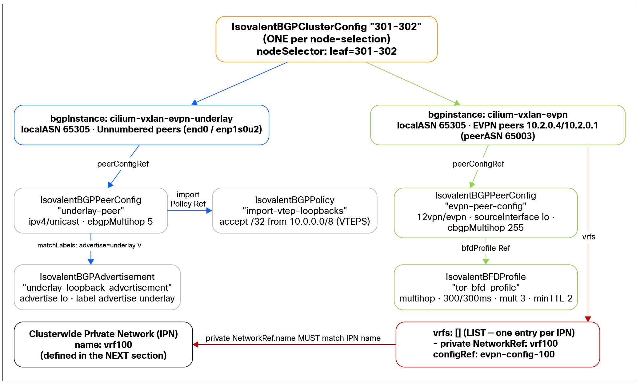
Cilium BGP underlay and overlay CRD relationships
Now we move on to the final configuration section—the IPN itself—completing the chain from the BGP vrfs list down to the network definition, EVPN advertisement, and fabric security group.
Reference configuration: IPN definition
Overview
This is the final piece of the Cilium configuration and the one the previous section's vrfs list points at. Here we define:
● The IPN itself (ClusterwidePrivateNetwork) — its subnets, routing, and VNI.
● The per-VRF EVPN BGP configuration (IsovalentBGPVRFConfig) referenced by the BGP cluster config's configRef.
● The advertisement that injects the IPN's prefixes into EVPN.
● An optional FabricSecurityGroup that maps workloads to an SGT based on Kubernetes labels.
Together with the BGP underlay/overlay from the previous section, this completes the end-to-end VXLAN EVPN handoff for a single IPN (vrf100, VNI 100).
Configuration
| --- apiVersion: isovalent.com/v1alpha1 kind: ClusterwidePrivateNetwork metadata: name: vrf100 # MUST match privateNetworkRef.name in the BGP vrfs list labels: vni: "100" spec: subnets: - name: subnet-0 cidrv4: 192.168.100.0/24 routes: - destination: 0.0.0.0/0 gateway: EVPN vni: 100 --- apiVersion: isovalent.com/v1alpha1 kind: IsovalentBGPVRFConfig metadata: name: evpn-config-100 # MUST match configRef in the BGP vrfs list spec: families: - afi: ipv4 safi: unicast advertisements: matchLabels: vrf: vrf100 --- apiVersion: isovalent.com/v1 kind: IsovalentBGPAdvertisement metadata: name: vrf100 labels: vrf: vrf100 spec: advertisements: - advertisementType: "PrivateNetwork" --- apiVersion: isovalent.com/v1alpha1 kind: FabricSecurityGroup metadata: name: "1001" spec: endpointSelector: matchLabels: app: vrf100-app1 |
Explanation of Key Elements
ClusterwidePrivateNetwork (vrf100) — the IPN
This is the actual Isovalent Private Network.
● metadata.name: vrf100 — The IPN's name. This is the link target for the BGP cluster config: the privateNetworkRef.name: vrf100 entry in the vrfs list resolves to this object. The names must match exactly.
● labels.vni: "100" and spec.vni: 100 — The EVPN L3VNI for this IPN. This is the value that ties the IPN to the corresponding VRF/VNI on the NX-OS leaf (the VRF-to-VNI mapping described in the “VXLAN EVPN Architecture” section), ensuring that the workload routes land in the correct tenant VRF on the fabric.
● spec.subnets[0]:
◦ name: subnet-0 — A logical name for the subnet.
◦ cidrv4: 192.168.100.0/24 — The IPN subnet the workloads live on.
◦ routes — The routing intent for the IPN, with gateway: EVPN indicating that the destination is reached via the EVPN handoff (i.e., out through the fabric over VXLAN EVPN), rather than locally.
0.0.0.0/0 → EVPN — The default route for the IPN points at EVPN. This tells the IPN to use the EVPN-learned routes whenever traffic is destined outside the IPN. In effect, this creates a two-stage routing behavior: Cilium first resolves traffic against the local IPN routes and forwards intra-IPN traffic locally over the pod CIDR, as explained in the “Intra-IPN east-west traffic” section. If a destination is not covered by a local route, it falls through to the default route—and because that default points to EVPN, the traffic is sent over the VXLAN EVPN handoff out to the fabric.
IsovalentBGPVRFConfig (evpn-config-100) — The per-VRF EVPN config
● metadata.name: evpn-config-100 — The link target for the BGP cluster config: the configRef: evpn-config-100 entry in the vrfs list resolves to this object. Again, the names must match exactly.
● families: ipv4/unicast with advertisements.matchLabels: vrf: vrf100 — Defines what this VRF advertises into EVPN, selecting advertisements labeled vrf: vrf100 (the advertisement object below).
IsovalentBGPAdvertisement (vrf100) — What gets advertised
● labels.vrf: vrf100 — Matched by the IsovalentBGPVRFConfig above (matchLabels: vrf: vrf100), wiring the advertisement to the VRF config.
● advertisementType: "PrivateNetwork" — Instructs Cilium to advertise the IPN's prefixes (the private-network routes, including the workload host routes) into EVPN. This is the object that actually injects the IPN into the EVPN control plane.
FabricSecurityGroup (1001) — Label-to-SGT mapping (optional)
● Maps workloads selected by endpointSelector.matchLabels: app: vrf100-app1 to SGT 1001.
● This is the concrete implementation of the label-based SGT mapping described in the “Workload-to-SGT mapping based on Kubernetes labels” section): Any endpoint carrying the label app: vrf100-app1 is classified into SGT 1001, and that SGT is propagated to the fabric as a BGP extended community alongside the EVPN host route, so the fabric can enforce group-based policy on it.
● Endpoints not matched by any FabricSecurityGroup fall back to the defaultGroupID set in the generic CiliumConfig (15 policy unaware).
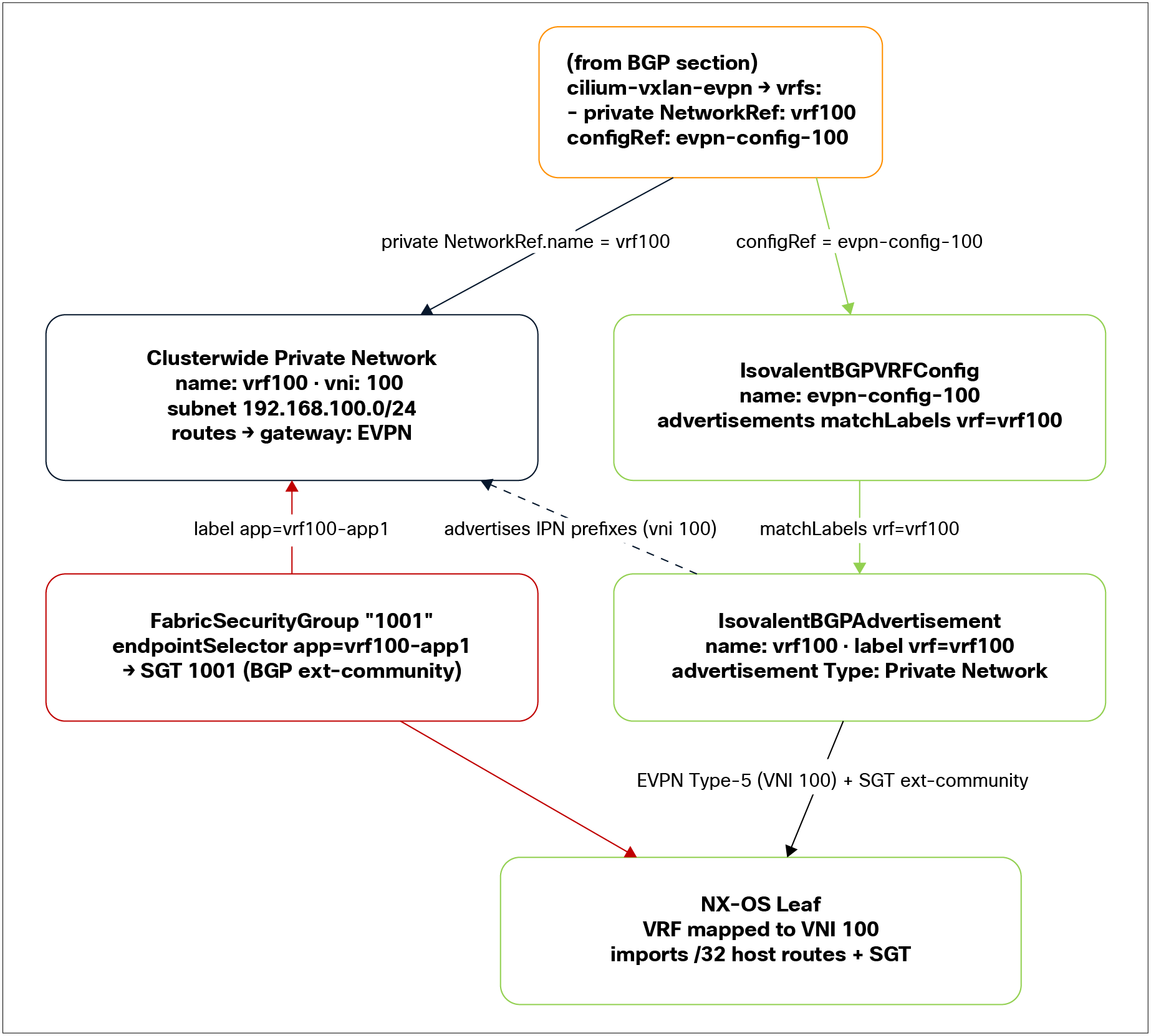
IPN definition
Overview
This is the configuration for the Local Access (VLAN) handoff, in which the fabric remains the gateway and routing authority and the node simply presents the IPN subnet on a tagged VLAN. There is no EVPN, no BGP, and no VTEP on the node; the cluster just hands the subnet to the fabric, which routes it using its normal pervasive/anycast gateway.
In practice, we are doing two things: enabling the IPN feature in Cilium and attaching an IPN subnet to a VLAN on a node interface, while the fabric provides the SVI or bridge domain gateway for that subnet.
Fabric-side configuration (not included)
On the fabric, Local Access requires nothing more than an SVI and a trunk (an EPG/bridge domain on ACI). These are standard, well-understood constructs that vary by environment, so they are intentionally not included in this template. The only requirements are that the IPN VLAN(s) are trunked to the node handoff port and that the fabric provides the pervasive/anycast gateway for the subnet.
Cilium feature enablement (difference from EVPN)
From a CiliumConfig perspective, the configuration is essentially the same as shown in the feature-enablement section (“Isovalent-side configuration”), with one key simplification: the only enterprise feature required is privateNetworks. The EVPN-specific features are not needed for Local Access:
● enterprise.bgpControlPlane — Not required
● enterprise.evpn (and securityGroupTags) — Not required
● BFD profiles — Not required
Only enterprise.privateNetworks (with networkAttachmentDefinitions if you want NAD-based attachment) needs to be enabled to use the Local Access handoff.
As noted in the overview, because there is no EVPN/BGP toward the fabric in this mode, Cilium does not propagate SGT/identity to the fabric. Fabric-side classification (EPG/ESG or SGT by VLAN/port/subnet) must be configured directly on the fabric.
Configuration
This example defines two IPNs — red (VLAN 107) and green (VLAN 108) — each mapped to a subnet, with the fabric as the gateway, and attached to node interface eth2.
| --- apiVersion: isovalent.com/v1alpha1 kind: ClusterwidePrivateNetwork metadata: name: cilium-ipn-red-vms-fab1 spec: subnets: - name: vlan107 cidrv4: 192.168.250.0/24 routes: - destination: 0.0.0.0/0 gateway: 192.168.250.254 # The fabric anycast gw dhcp: mode: relay relay: serverAddress: 198.18.154.233 serverPort: 67 # default: 67 option82: # optional DHCP Option 82 suboptions circuitID: "vlan107" remoteID: "fab1" --- apiVersion: isovalent.com/v1alpha1 kind: PrivateNetworkNodeAttachment metadata: name: cilium-ipn-red-vms-fab1 spec: privateNetworkRef: name: cilium-ipn-red-vms-fab1 nodeSelector: # Optional: target specific nodes matchLabels: attachments: - interface: eth2 # Physical interface on the node subnetRefs: - name: vlan107 vlanID: 107 --- apiVersion: isovalent.com/v1alpha1 kind: ClusterwidePrivateNetwork metadata: name: cilium-ipn-green-vms-fab1 spec: subnets: - name: vlan108 cidrv4: 192.168.251.0/24 routes: - destination: 0.0.0.0/0 gateway: 192.168.251.254 --- apiVersion: isovalent.com/v1alpha1 kind: PrivateNetworkNodeAttachment metadata: name: cilium-ipn-green-vms-fab1 spec: privateNetworkRef: name: cilium-ipn-green-vms-fab1 nodeSelector: # Optional: target specific nodes matchLabels: priv-net: cilium-ipn-vms-fab1 attachments: - interface: eth2 # Physical interface on the node subnetRefs: - name: vlan108 vlanID: 108 |
Explanation of key elements
ClusterwidePrivateNetwork — The IPN (VLAN-backed)
Each IPN defines a subnet whose gateway is the fabric, not EVPN. This is the key difference from the EVPN configuration.
Table 5. Explanation of configuration fields
| Field |
Purpose |
| metadata.name |
The IPN name; referenced by the matching PrivateNetworkNodeAttachment. |
| subnets[].name (vlan107 / vlan108) |
Logical subnet name, referenced by the attachment's subnetRefs. |
| cidrv4 |
The IPN subnet (192.168.250.0/24 / 192.168.251.0/24). |
| routes[].destination: 0.0.0.0/0 + gateway: <fabric IP> |
Default route pointing at the fabric's pervasive/anycast gateway (192.168.250.254 / 192.168.251.254) — i.e., the fabric SVI/BD address for the subnet. Note that this is a real gateway IP, not the EVPN keyword used in the EVPN handoff. |
DHCP relay (optional, shown on the red IPN)
● dhcp.mode: relay — The node relays DHCP requests to an external server rather than serving them locally.
● relay.serverAddress / serverPort — The external DHCP server and port (67 by default).
● relay.option82 — Optional Option 82 suboptions (circuitID: "vlan107", remoteID: "fab1") to tag relayed requests, useful for per-VLAN/per-fabric identification and IP-assignment policy on the DHCP server.
DHCP relay is optional and shown only on the red IPN here; the green IPN omits it.
PrivateNetworkNodeAttachment — Binding the IPN to node interfaces
This is what places the IPN's VLAN onto the node.
Table 6. Explanation of attachment fields
| Field |
Purpose |
| privateNetworkRef.name |
Links the attachment to its ClusterwidePrivateNetwork (names must match). |
| nodeSelector.matchLabels |
Optional — Restricts the attachment to specific nodes. The red IPN leaves it empty (apply broadly); the green IPN targets nodes labeled priv-net: cilium-ipn-vms-fab1. |
| attachments[].interface (eth2) |
The physical interface on the node used for the handoff. |
| attachments[].subnetRefs |
References the subnet (vlan107 / vlan108) within the IPN. |
| attachments[].vlanID (107 / 108) |
The 802.1q VLAN tag applied toward the fabric. |
As described in the “Local Access (VLAN) Architecture” section, the VLAN subinterface on the node is provisioned by Cilium based on this attachment — the operator does not configure node interfaces by hand. Multiple IPNs can share the same physical interface (eth2 here) using different VLAN IDs.
Reference configuration: Placing a VM in an IPN
Placing a VM into an IPN it is done declaratively with a simple annotation on the VM. The annotation tells INV which IPN (and subnet) the VM belongs to, and optionally which IP it should be assigned:
| apiVersion: kubevirt.io/v1 kind: VirtualMachine metadata: name: vm1 spec: runStrategy: Always template: metadata: annotations: privnet.isovalent.com/network-attachment: |- { "network": "network-app-1", "subnet": "subnet-0", "ipv4": "192.168.250.10", "ipv6": "fd10:0:250::10", } labels: app: inb-demo spec: ###Your VM Spec### |
Once the privnet.isovalent.com/network-attachment annotation is present, the control plane handles the rest: the VM is connected into the specified IPN/subnet.
The VM will then need to be configured by the admin or via a cloudInit template with the appropriate networking configuration. For example:
| cloudInitNoCloud: networkData: | version: 2 ethernets: eth0: addresses: [ 192.168.250.10/32, fd10:0:250::10/128 ] gateway4: 169.254.0.1 gateway6: fe80::1 |
It is also possible to create multihomed workloads with Multus, where a workload has multiple network interfaces, each attached to a separate private network.
Refer to the Isovalent Networking for Virtualization (https://docs.isovalent.com/latest/inv/index.html) configuration guide for more details.