Lenovo Hybrid AI 285 with Cisco Networking AI-Ready Data Center Validated Design Guide
Available Languages
Bias-Free Language
The documentation set for this product strives to use bias-free language. For the purposes of this documentation set, bias-free is defined as language that does not imply discrimination based on age, disability, gender, racial identity, ethnic identity, sexual orientation, socioeconomic status, and intersectionality. Exceptions may be present in the documentation due to language that is hardcoded in the user interfaces of the product software, language used based on RFP documentation, or language that is used by a referenced third-party product. Learn more about how Cisco is using Inclusive Language.
Lenovo Hybrid AI 285 is a platform that enables enterprises of all sizes to quickly deploy hybrid AI factory infrastructure, supporting Enterprise AI use cases as either a new, greenfield environment or an extension of their existing IT infrastructure. The Lenovo Hybrid AI 285 platform, combined with Cisco Networking, offers a validated design for enterprises to deploy hybrid AI infrastructure.
This guide provides a step-by-step approach to implementing Cisco Networking and Cisco Nexus® Dashboard and refers users to the foundational Lenovo Hybrid AI 285 platform guide as necessary.
The Lenovo Hybrid AI 285 is a platform based on the NVIDIA 2-8-5 PCIe-optimized configuration — 2x CPUs, 8x GPUs, and 5x network adapters — and is ideally suited for medium (per GPU) to large (per node) Inference use cases and for small-to-large model training or fine-tuning, depending on the chosen scale. It combines market-leading GPU-rich Lenovo ThinkSystem servers with options to be equipped with NVIDIA L40S, H200 NVL, or RTX PRO 6000 Blackwell Server Edition GPUs with Cisco Networking. It enables the use of the NVIDIA AI Enterprise (NVAIE) software stack with NVIDIA Blueprints. In this validation, we are using NVIDIA L40S GPUs.
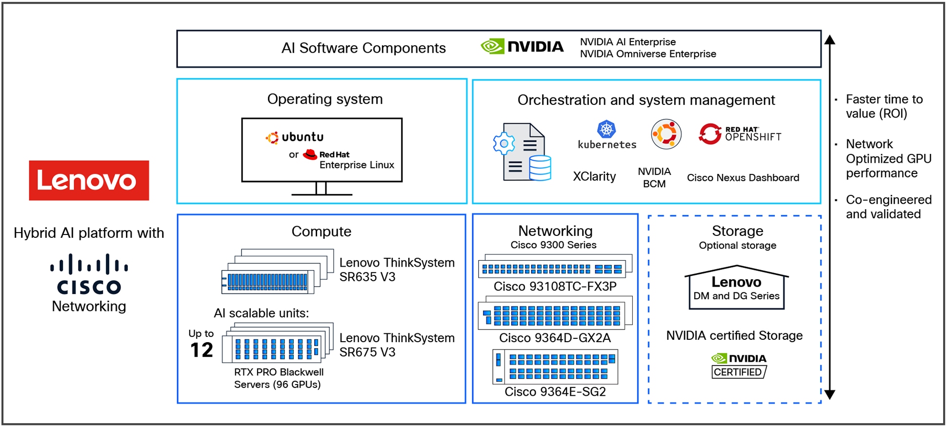
Lenovo Hybrid AI 285 platform overview with Cisco Networking
The Lenovo Hybrid AI 285 Platform with Cisco Networking scales from a starter-kit environment with between 4 and 32 PCIe GPUs to a Scalable Unit deployment (SU) with four servers and 32 GPUs in each SU and up to 3 scalable units with 12 servers and 96 GPUs. See Figure 2 for a sizing overview.
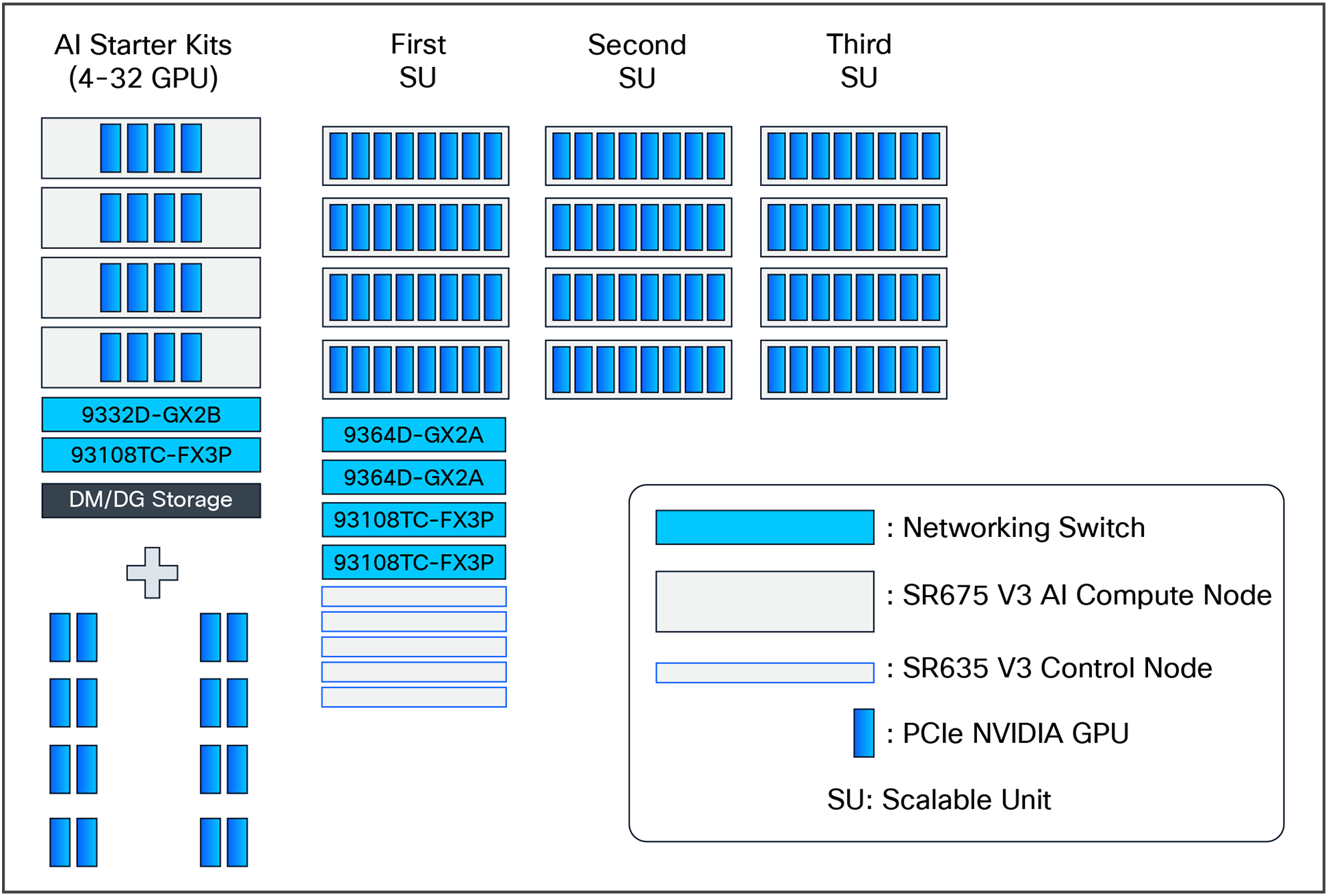
Lenovo Hybrid AI 285 with Cisco Networking scaling from starter kit to 96 GPUs
Figure 3 shows the networking architecture of the platform deployed with 96 GPUs.
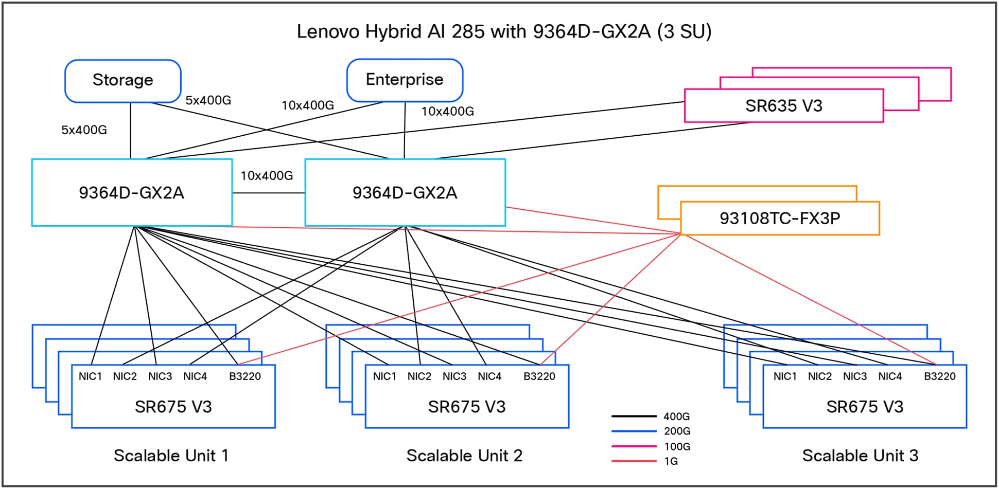
Lenovo Hybrid AI 285 with Cisco Networking platform with three scalable units
Platform overview
The Lenovo Hybrid AI 285 platform is built on the NVIDIA 2-8-5 PCIe-optimized configuration:
● 2 CPUs, 8 GPUs, and 5 network adapters
● Designed for medium-to-large inference and model training workloads
● Consists of Lenovo ThinkSystem SR675 V3 servers with GPUs and NICs based on use-case and SR635 V3 servers as additional service nodes to manage the overall AI cluster environment such as management, orchestration, etc.
Scalability:
● Starter kit: 4 GPUs
● Scalable Unit (SU):4 servers, 32 GPUs per SU
● Maximum deployment: 3 SUs, 12 servers, 96 GPUs
In summary, here are the key features:
● Scalability: from a starter kit (4 GPUs) to a full-scale deployment (96 GPUs across 3 scalable units)
● Flexibility: supports NVIDIA GPUs (L40S, H200 NVL, and RTX PRO 6000) and NVIDIA AI Enterprise software stack
● Performance: optimized for medium-to-large inference and training workloads
The main hardware components of Lenovo Hybrid AI 285 platforms are compute nodes and the Cisco Networking infrastructure. As an integrated solution, they are combined in either a Lenovo EveryScale Rack (Machine Type 1410) or Lenovo EveryScale Client Site Integration Kit (Machine Type 7X74).
Topics in this section:
The AI compute node leverages the GPU-rich Lenovo ThinkSystem SR675 V3 server.
The SR675 V3 is a 2-socket 5th Gen AMD EPYC 9005 server supporting up to 8 PCIe DW GPUs with up to 5 network adapters in a 3-Unit (3U) rack server chassis. This makes it the ideal choice for NVIDIA’s 2-8-5 configuration requirements.
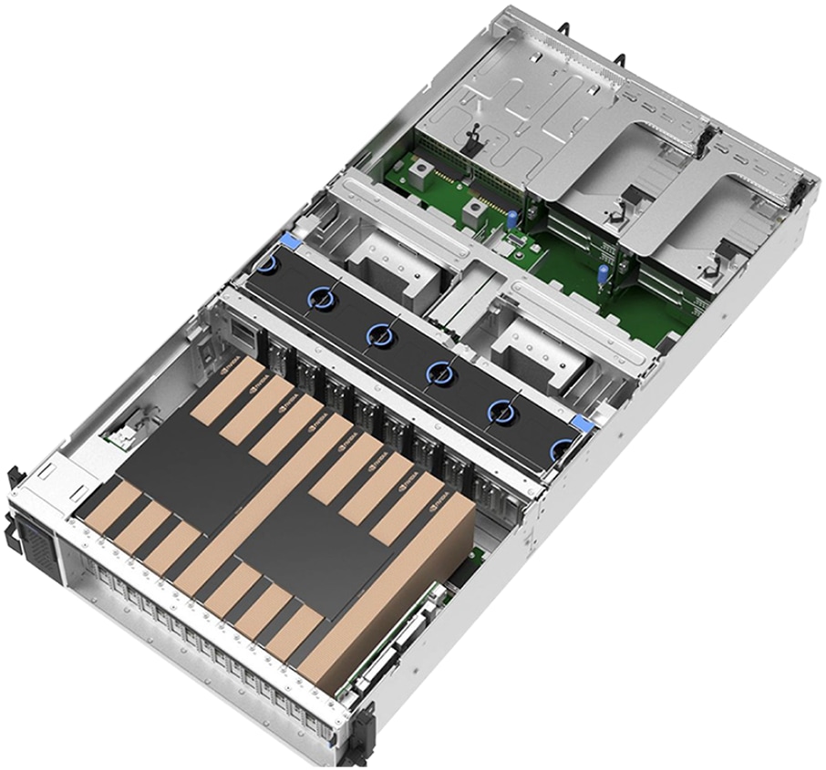
Lenovo ThinkSystem SR675 V3 in 8 PCIe DW setup
AI compute node: Lenovo ThinkSystem SR675 V3
● Processor: Dual AMD EPYC 9535 (64 cores, 2.4 GHz, 3.5 GHz boost)
● GPU support: Up to 8 NVIDIA GPUs (L40S, H200 NVL, RTX PRO 6000)
● Network adapters: 5 PCIe Gen5 slots for low-latency NVIDIA GPUDirect
● Storage: RAID1 OS drives and high-capacity NVMe drives for application data
The AI compute node is configured with two AMD EPYC 9535 64 core 2.4 GHz processors with an all-core boost frequency of 3.5 GHz. Besides providing consistently more than 2 GHz frequency, this ensures that, with seven NVIDIA Multi-Instance GPUs (MIG) on eight physical GPUs, there are two cores available per MIG plus a few additional cores for the operating system and other operations.
The GPUs are connected to the CPUs through two PCIe Gen5 switches, each supporting up to four GPUs. With the NVIDIA H200 NVL PCIe GPU, the four GPUs are additionally interconnected through an NVLink bridge, creating a unified memory space. In an entry configuration with two GPUs per PCIe switch, the Lenovo ThinkSystem SR675 V3 supports connecting all four GPUs with an NVLink bridge for maximized shared memory, thereby accommodating larger inference models. With the NVIDIA RTX PRO 6000 Blackwell Server Edition, no NVLink bridge is applicable; the same applies to configurations with the L40S. For this test, we are using the 4x L40S GPUs on each compute-server system.
The Ethernet adapters for the compute (east/west) network are directly connected to the GPUs through PCIe switches, thus minimizing latency and enabling NVIDIA GPUDirect and GPUDirect storage operations. For pure inference workloads, they are optional, but for training and fine-tuning operations, they should provide at least 200 Gb/s per GPU.
Finally, the system is completed by local storage with two 960 GB read-intensive M.2 in a RAID1 configuration for the operating system and four 3.84 TB read-intensive E3.S drives for local application data.
The default setup leverages Cisco Networking with the Nexus 9364D-GX2A for the converged and compute network.
Cisco Nexus 9364D-GX2A switch
The Cisco Nexus 9364D-GX2A is a 2-Rack-Unit (2RU) switch that supports 25.6 Tbps of bandwidth and 8.35 bpps across 64 fixed 400G QSFP-DD ports and two fixed 1/10G SFP+ ports. QSFP-DD ports also support native 200G (QSFP56), 100G (QSFP28), and 40G (QSFP+). Each port can also support 4x 10G, 4x 25G, 4x 50G, 4x 100G, and 2x 200G breakouts.
It supports flexible configurations, including 128 ports of 200GbE or 256 ports of 100/50/25/10GE ports, thereby accommodating diverse AI cluster requirements.
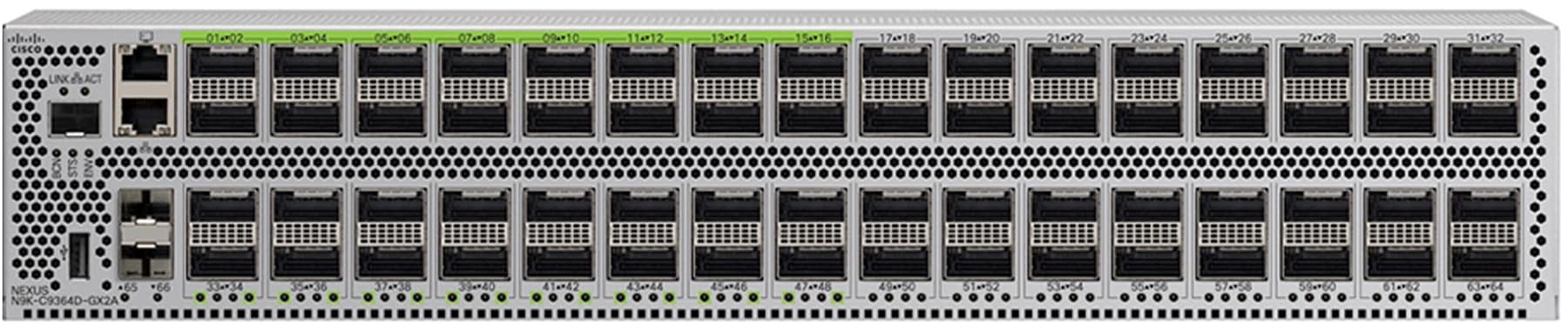
Cisco Nexus 9364D-GX2A switch
Cisco Nexus 9300-FX3 Series Switch
The Cisco Nexus 93108TC-FX3P Series Switch is a high-performance, fixed-port switch designed for modern data centers. It features 48 ports of 100M/1/2.5/5/10GBASE-T, providing flexible connectivity options for various network configurations. Additionally, it includes six uplink ports that support 40/100 Gigabit Ethernet QSFP28, ensuring high-speed data transfer and scalability.
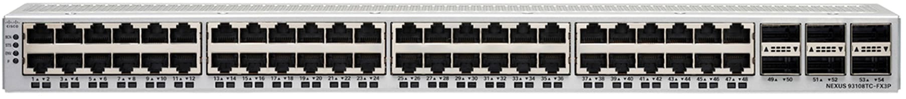
Cisco Nexus 93108TC-FX3P Series Switch
The out-of-band (management) network encompasses all AI compute nodes and NVIDIA BlueField-3 DPU Base Management Controllers (BMCs) as well as the network infrastructure management.
Cisco Nexus Dashboard
Cisco Nexus Dashboard, included with every Cisco Nexus 9000 Series Switch tiered licensing purchase, serves as a centralized hub that unifies disparate network configurations and views from multiple switches and data centers. For AI fabric operations, it acts as the ultimate command center, from the initial setup of AI fabric automation to continuous fabric analytics with few clicks.

AI fabric workflow on Cisco Nexus Dashboard
Key capabilities of Cisco Nexus Dashboard, such as congestion scoring, PFC/ECN statistics, and microburst detection, empower organizations to proactively identify and address performance bottlenecks for their AI backend infrastructure.
Advanced features, including anomaly detection, event correlation, and suggested remediation, ensure that networks are not only resilient but also self-healing, thus minimizing downtime and accelerating issue resolution.
Cisco Nexus Dashboard offers flexible deployment options—including physical appliances (pND) on Cisco UCS® M6 and M8 servers, a virtual appliance (vND) for existing virtual infrastructure, and a cloud-hosted option—thereby meeting diverse data-center needs. These options deliver high performance, scalability, and simplified management across LAN, SAN, and IPFM environments without requiring dedicated hardware. The installation and deployment guide is available here.
Server configuration and tuning
Server hardware configuration
The AI compute node is configured with two AMD EPYC 9535 64 Core 2.4 GHz processors with an all-core boost frequency of 3.5GHz. The GPUs are connected to the CPUs through two PCIe Gen5 switches, each supporting up to four GPUs. The Ethernet adapters for the compute (east/west) network are directly connected to the GPUs through PCIe switches, thus minimizing latency and enabling NVIDIA GPUDirect and GPUDirect Storage operations. For this test, we are using the 4x NVIDIA L40S GPUs on each compute-server system. The system is completed by local storage with two 960GB read-intensive M.2 in a RAID1 configuration for the operating system and four 3.84TB read-intensive E3.S drives for local application data.
Understanding NUMA domains
The Lenovo ThinkSystem SR675 V3 is a dual-socket AI compute node. The architecture divides the system into two non-uniform memory access (NUMA) domains, one associated with each CPU socket. For optimal AI workload performance, it is crucial to ensure that the process threads and the data they operate on are allocated within the same local NUMA domain.
Four NVIDIA L40S GPUs and two NVIDIA BlueField3 B3140H NICs are configured in the AI compute nodes for this testing. To optimize performance and minimize latency, the first 2x GPUs and 1x NIC are installed on NUMA0, and the other 2x GPUs and 1x NIC are installed on NUMA1.
BIOS UEFI best practices
Properly configuring UEFI parameters in a server is important for achieving a desired outcome such as high performance or efficiency. For AI compute nodes, the UEFI operating-mode setting should be set to “Maximum Performance Mode.”
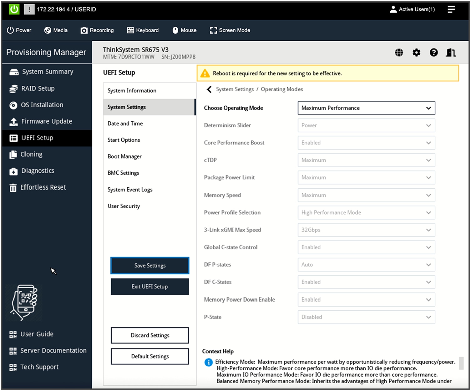
UEFI setup operating mode
For custom mode-configurations, these additional settings are required: enable both P-state (performance state) and CPPC (collaborative processor performance control).
OS-level performance tuning
Set the frequency governor to performance:
# cpupower frequency-set --governor performance
. . .
# cpupower frequency-info
analyzing CPU 82:
driver: acpi-cpufreq
CPUs which run at the same hardware frequency: 82
CPUs which need to have their frequency coordinated by software: 82
maximum transition latency: Cannot determine or is not supported.
hardware limits: 1.50 GHz - 2.45 GHz
available frequency steps: 2.45 GHz, 1.90 GHz, 1.50 GHz
available cpufreq governors: conservative ondemand userspace powersave performance schedutil
current policy: frequency should be within 1.50 GHz and 2.45 GHz.
The governor "performance" may decide which speed to use
within this range.
current CPU frequency: 2.45 GHz (asserted by call to hardware)
boost state support:
Supported: yes
Active: yes
Boost States: 0
Total States: 3
Pstate-P0: 2450MHz
Pstate-P1: 1900MHz
Pstate-P2: 1500MHz
Disable idle state 2 and 1 (disabling 1 is optional):
#cpupower idle-set -d 2
#cpupower idle-set -d 1
Software stack on Lenovo servers
Deploying AI to production involves implementing multiple layers of software. The process begins with server BIOS tuning, system management, and the operating system of the compute nodes. It progresses through workload or container scheduling and cluster management. And it culminates in the AI software stack that enables delivering AI tools and agents to users.
For an AI starter kit deployment, the Kubernetes control plane operates directly on the AI compute nodes, negating the requirement for dedicated service nodes to run the Kubernetes control plane. The AI compute nodes will function as primary-secondary nodes. A minimum of one service node is still required to run NVIDIA Base Command Manager (BCM). The software stack for AI starter kit or single-node deployments is similar to the full AI software stack, though some components may be considered optional or less practical for these smaller configurations.
Table 1. Lenovo AI software stack
| Software role |
Software package |
| Bare-metal management |
Lenovo XClarity One Management Hub 2.0 |
| Lenovo XClarity One (cloud or on-premises VM) |
|
| Linux operating system |
Ubuntu Server 22.04.4 LTS |
| Container orchestration |
Upstream Kubernetes 1.31.5 |
| Container runtime |
Containerd 1.7.23 |
| Orchestration |
NVIDIA Base Command Manager 10.0 |
| Prometheus 2.55.0 |
|
| Permission-Manager 0.5.1 |
|
| Container network interface (CNI) |
Calico 3.27.4 |
| Package manager |
Helm 3.16.0 |
| Load balancer – control plane |
NGINX 1.12.0 |
| Load balancer – network services |
MetalLB 0.14.8 |
| Operator |
NVIDIA GPU Operator 24.9.2 |
| Linux GPU driver 550.127.05 |
|
| NVIDIA NIM Operator 1.0.1 |
|
| NVIDIA Network Operator v25.1.0 |
|
| DOCA host |
2.9.0-0.4.7 |
| NCCL |
2.21 |
| Grafana |
11.2.2 |
| Storage |
NFS Provisioner 4.0.2 |
| Local Path Provisioner 0.0.31 |
Lenovo and Cisco AI network validated deployment
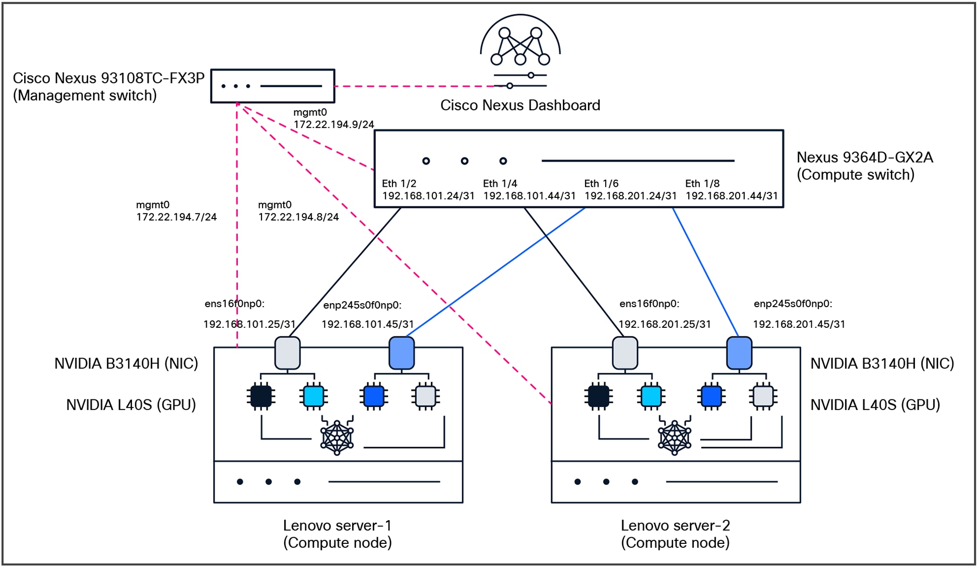
Test topology
The key purpose of the testing is to make sure we understand the lossless fabric configurations required for high networking-performance and replicate them in different environments (NVIDIA L40S, H200 NVL, or RTX PRO 6000 Blackwell Server Edition GPUs systems). The following components were used for testing:
● Compute:
◦ 2x Lenovo SR675v3 with NVIDIA L40S, NVIDIA BlueField-3 B3140H for east/west communication, NVIDIA BlueField-3 B3220 for north/south communication
◦ Ubuntu Server 22.04.4 LTS
● Network:
◦ Cisco Nexus 9364D-GX2A (NX-OS: 10.5.3(F))
● Network management:
◦ Cisco Nexus Dashboard (4.1.1g)
● Optics:
◦ Cisco N9364D-GX2A: QSFP-DD-400G-DR4 with CB-M12-M12-SMF cable
◦ NVIDIA B3140H: QSFP-400G-DR4 with CB-M12-M12-SMF cable
● License:
◦ Cisco Data Center Networking (Cisco DCN) Advantage for the Cisco Nexus switch
Verification steps for OS and drivers
1. Verifying that CUDA driver is properly installed and running:
The first and most important verification step is to use the NVIDIA System Management Interface (nvidia-smi) command-line utility. This tool is essential for monitoring GPU status, checking driver versions, and managing GPU states.
Running this command successfully confirms that the kernel driver is loaded correctly and can communicate with the GPU hardware.
tester@ubuntu-ai-1:~$ nvidia-smi
Fri Oct 17 16:01:12 2025
+-----------------------------------------------------------------------------------------+
| NVIDIA-SMI 575.64.03 Driver Version: 575.64.03 CUDA Version: 12.9 |
|-----------------------------------------+------------------------+----------------------+
| GPU Name Persistence-M | Bus-Id Disp.A | Volatile Uncorr. ECC |
| Fan Temp Perf Pwr:Usage/Cap | Memory-Usage | GPU-Util Compute M. |
| | | MIG M. |
|=========================================+========================+======================|
| 0 NVIDIA L40S Off | 00000000:03:00.0 Off | 0 |
| N/A 33C P8 33W / 350W | 0MiB / 46068MiB | 0% Default |
| | | N/A |
+-----------------------------------------+------------------------+----------------------+
| 1 NVIDIA L40S Off | 00000000:04:00.0 Off | 0 |
| N/A 31C P8 33W / 350W | 0MiB / 46068MiB | 0% Default |
| | | N/A |
+-----------------------------------------+------------------------+----------------------+
| 2 NVIDIA L40S Off | 00000000:83:00.0 Off | 0 |
| N/A 31C P8 34W / 350W | 0MiB / 46068MiB | 0% Default |
| | | N/A |
+-----------------------------------------+------------------------+----------------------+
| 3 NVIDIA L40S Off | 00000000:84:00.0 Off | 0 |
| N/A 31C P8 32W / 350W | 0MiB / 46068MiB | 0% Default |
| | | N/A |
+-----------------------------------------+------------------------+----------------------+
+-----------------------------------------------------------------------------------------+
| Processes: |
| GPU GI CI PID Type Process name GPU Memory |
| ID ID Usage |
|=========================================================================================|
| No running processes found |
2. Verifying the NVIDIA DOCA installation and NVIDIA BlueField-3 Status:
You must verify that the NVIDIA BlueField-3 is recognized correctly by the host and that the internal NVIDIA DOCA services on the DPU are operational. This verification process is divided into two parts: checks performed on the host server and checks performed directly on the NIC.
Check PCIe device recognition (lspci)
First, verify that the host system detects the NVIDIA BlueField DPU on the PCIe bus.
tester@ubuntu-ai-1:~$ lspci | grep Mellanox
31:00.0 Ethernet controller: Mellanox Technologies MT43244 BlueField-3 integrated ConnectX-7 network controller (rev 01)
31:00.1 DMA controller: Mellanox Technologies MT43244 BlueField-3 SoC Management Interface (rev 01)
75:00.0 Ethernet controller: Mellanox Technologies MT43244 BlueField-3 integrated ConnectX-7 network controller (rev 01)
75:00.1 DMA controller: Mellanox Technologies MT43244 BlueField-3 SoC Management Interface (rev 01)
85:00.0 Ethernet controller: Mellanox Technologies MT43244 BlueField-3 integrated ConnectX-7 network controller (rev 01)
85:00.1 Ethernet controller: Mellanox Technologies MT43244 BlueField-3 integrated ConnectX-7 network controller (rev 01)
85:00.2 DMA controller: Mellanox Technologies MT43244 BlueField-3 SoC Management Interface (rev 01)
c1:00.0 Ethernet controller: Mellanox Technologies MT43244 BlueField-3 integrated ConnectX-7 network controller (rev 01)
c1:00.1 DMA controller: Mellanox Technologies MT43244 BlueField-3 SoC Management Interface (rev 01)
f5:00.0 Ethernet controller: Mellanox Technologies MT43244 BlueField-3 integrated ConnectX-7 network controller (rev 01)
f5:00.1 DMA controller: Mellanox Technologies MT43244 BlueField-3 SoC Management Interface (rev 01)
Check device status with Mellanox Software Tools (mst status)
The Mellanox Software Tools (MST) provide a more detailed status. This is the most common tool used to manage NVIDIA networking devices.
tester@ubuntu-ai-1:~$ sudo mst start
Starting MST (Mellanox Software Tools) driver set
Loading MST PCI module - Success
[warn] mst_pciconf is already loaded, skipping
Create devices
Unloading MST PCI module (unused) – Success
tester@ubuntu-ai-1:~$ sudo mst status -v
MST modules:
------------
MST PCI module is not loaded
MST PCI configuration module loaded
PCI devices:
------------
DEVICE_TYPE MST PCI RDMA NET NUMA
BlueField3(rev:1) /dev/mst/mt41692_pciconf4 f5:00.0 mlx5_2 net-enp245s0f0np0 1
BlueField3(rev:1) /dev/mst/mt41692_pciconf3 c1:00.0 mlx5_5 net-enp193s0f0np0 1
BlueField3(rev:1) /dev/mst/mt41692_pciconf2.1 85:00.1 mlx5_4 net-enp133s0f1np1 1
BlueField3(rev:1) /dev/mst/mt41692_pciconf2 85:00.0 mlx5_3 net-enp133s0f0np0 1
BlueField3(rev:1) /dev/mst/mt41692_pciconf1 75:00.0 mlx5_1 net-ens16f0np0 0
BlueField3(rev:1) /dev/mst/mt41692_pciconf0 31:00.0 mlx5_0 net-ens15f0np0 0
3. Verifying NIC status and mapping
Before configuring RoCEv2, it is essential to verify that the system correctly recognizes the RDMA-capable Network Interface Cards (RNICs) and to identify their corresponding Linux network interface names. The ibdev2netdev utility is the standard tool for this task.
This command maps the low-level InfiniBand device names to the familiar kernel network interface names that are used for IP addressing and other network configurations.
tester@ubuntu-ai-1:~$ ibdev2netdev
mlx5_0 port 1 ==> ens15f0np0 (Up)
mlx5_1 port 1 ==> ens16f0np0 (Up)
mlx5_2 port 1 ==> enp245s0f0np0 (Up)
mlx5_3 port 1 ==> enp133s0f0np0 (Up)
mlx5_4 port 1 ==> enp133s0f1np1 (Down)
mlx5_5 port 1 ==> enp193s0f0np0 (Up)
4. Configuring per-source interface routing with netplan
This configuration is designed for a server with two or more network interfaces connected to different subnets, each with its own gateway. The goal is to ensure that when the server initiates traffic from an IP address on one interface, it uses the gateway associated with that specific interface, rather than relying on a single, global default gateway. In this example, we are using enp133s0f0np0 for management while others are used as data interfaces.
Below is an example of a netplan. Please use the interfaces and IP addressing scheme according to your setup requirements.
tester@ubuntu-ai-1:~$ sudo cat /etc/netplan/00-installer-config.yaml
network:
ethernets:
enp133s0f0np0:
addresses:
- 172.22.194.7/24
nameservers:
addresses:
- 171.70.168.183
search:
- cisco.com
routes:
- to: default
via: 172.22.194.1
enp133s0f1np1:
dhcp4: true
enp245s0f0np0:
dhcp4: true
ens15f0np0:
dhcp4: true
ens16f0np0:
mtu: 9000
dhcp4: false
addresses:
- 192.168.101.25/31
routing-policy:
- from: 192.168.101.25
table: 101
routes:
- to: 0.0.0.0/0
via: 192.168.101.24
table: 101
enp245s0f0np0:
mtu: 9000
dhcp4: false
addresses:
- 192.168.101.45/31
routing-policy:
- from: 192.168.101.45
table: 102
routes:
- to: 0.0.0.0/0
via: 192.168.101.44
table: 102
version: 2
When you make changes to your netplan YAML configuration files, you need to apply them to the system. Once applied, we need restart the networking service:
sudo netplan apply
sudo systemctl restart systemd-networkd
5. Verify connectivity between interfaces on the servers
tester@ubuntu-ai-1:~$ ping -I 192.168.101.45 192.168.201.45
PING 192.168.201.45 (192.168.201.45) from 192.168.101.45 : 56(84) bytes of data.
64 bytes from 192.168.201.45: icmp_seq=1 ttl=63 time=15.3 ms
64 bytes from 192.168.201.45: icmp_seq=2 ttl=63 time=0.673 ms
64 bytes from 192.168.201.45: icmp_seq=3 ttl=63 time=0.833 ms
64 bytes from 192.168.201.45: icmp_seq=4 ttl=63 time=0.853 ms
64 bytes from 192.168.201.45: icmp_seq=5 ttl=63 time=0.844 ms
^C
--- 192.168.201.45 ping statistics ---
5 packets transmitted, 5 received, 0% packet loss, time 4074ms
rtt min/avg/max/mdev = 0.673/3.710/15.348/5.819 ms
6. Configure RoCEv2, ECN, and PFC on the NICs (follow instructions in the NVIDIA documentation)
● Set mode to RoCEv2 on the NIC
sudo cma_roce_mode -d mlx5_1 -p 1 -m 2
● Set Type of Service (ToS) 104
sudo cma_roce_tos -d mlx5_1 -t 104
● Map ToS 104 to traffic-class 1 (TC1)
sudo bash -c echo 104 > /sys/class/infiniband/mlx5_1/tc/1/traffic_class'
● PFC and DSCP-based classification for class 3
sudo bash -c 'echo 1 > /sys/class/net/ens1f1np1/ecn/roce_np/enable/3'
sudo mlnx_qos -i ens1f1np1 --trust=dscp --pfc 0,0,0,1,0,0,0,0
● Enable ECN and change the CNP packets DSCP value to 48
sudo sysctl -w net.ipv4.tcp_ecn=1
sudo bash -c 'echo 6 > /sys/class/net/ens1f1np1/ecn/roce_np/cnp_802p_prio'
sudo bash -c 'echo 48 > /sys/class/net/ens1f1np1/ecn/roce_np/cnp_dscp'
Configuring Cisco Nexus 9000 Series Switches with CLI
1. Configuring a lossless fabric for RoCEv2
To create a high-performance, lossless network fabric suitable for traffic such as RoCEv2, Priority Flow Control (PFC) and Explicit Congestion Notification (ECN) must be configured to work together. This guide explains the necessary command-line configurations using the Cisco Modular Quality of Service (MQC) framework on Cisco Nexus 9000 Series Switches.
The MQC framework separates the configuration into three logical parts:
● type qos: classifies incoming traffic based on markers such as DSCP and assigns it to an internal qos-group
● type queuing: defines how traffic is buffered, scheduled, and handled during congestion (for example, bandwidth allocation and ECN/WRED)
● type network-qos: configures system-level lossless characteristics, such as enabling PFC for specific traffic classes
The following example demonstrates a complete configuration applied to all switches and interfaces in the fabric. The goal is to properly handle RoCEv2 traffic (marked with DSCP 26) and its associated Congestion Notification Packet (CNP) traffic (marked with DSCP 48).
Step 1: Classify incoming traffic (type qos)
First, we must identify the RoCEv2 and CNP traffic as it enters the switch. We create class maps to match their DSCP values and then a policy map to assign them to internal qos-groups. This qos-group acts as a tag that other QoS policies will use to identify the traffic.
● class-map: matches RoCEv2 traffic (DSCP 26) and CNP traffic (DSCP 48)
● policy-map: assigns matched RoCEv2 traffic to qos-group 3 and CNP traffic to qos-group 7. All other traffic is assigned to the default qos-group 0.
class-map type qos match-any CNP
match dscp 48
class-map type qos match-any ROCEv2
match dscp 26
policy-map type qos QOS_classification_policy
class class-q3
set qos-group 3
class class-q7
set qos-group 7
class class-default
set qos-group 0
2. Define queuing and congestion behavior (type queuing)
Next, we define how the classified traffic is handled in the egress queues. This policy uses the qos-groups assigned in step 1 to apply specific queuing behaviors.
● CNP traffic (qos-group 7): placed in a strict priority queue (priority level 1) to ensure that these critical notifications are never delayed
● RoCEv2 traffic (qos-group 3): allocated 50 percent of the remaining bandwidth. ECN is enabled on this queue using Weighted Random Early Detection (WRED). When the queue depth reaches the minimum threshold (150 KB), the switch begins marking packets with an ECN flag instead of dropping them. The maximum threshold (3000 KB) defines the upper limit. These values are optimized for high-speed 100G/400G networks.
● Default traffic: receives the remaining 50 percent of the bandwidth
policy-map type queuing custom-8q-out-policy
class type queuing c-out-8q-q7
priority level 1
class type queuing c-out-8q-q6
bandwidth remaining percent 0
class type queuing c-out-8q-q5
bandwidth remaining percent 0
class type queuing c-out-8q-q4
bandwidth remaining percent 0
class type queuing c-out-8q-q3
bandwidth remaining percent 50
random-detect minimum-threshold 150 kbytes maximum-threshold 3000 kbytes drop-probability 7 weight 0 ecn
class type queuing c-out-8q-q2
bandwidth remaining percent 0
class type queuing c-out-8q-q1
bandwidth remaining percent 0
class type queuing c-out-8q-q-default
bandwidth remaining percent 50
3. Enable lossless behavior (type network-qos)
This policy enables PFC for the specific traffic class carrying RoCEv2 traffic, making its queue lossless.
● pause pfc-cos 3: enables the generation and processing of PFC pause frames for Class of Service (CoS) 3. This command links PFC to the queue handling RoCEv2 traffic (qos-group 3), preventing packet drops during congestion by pausing transmission.
● mtu 9216: sets a jumbo MTU. While this does not directly enforce an MTU on traffic, it is used by the system to properly calculate the headroom buffer required for the lossless queue.
● PFC thresholds: The xOFF (pause) and xON (resume) thresholds are left at their default values and are not displayed in the configuration.
policy-map type network-qos custom-8q-nq-policy
<...>
class type network-qos c-8q-nq3
mtu 9216
pause pfc-cos 3
<...>
4. Apply the policies
Finally, the policies must be attached to the correct scopes to become active.
System-wide application
The queuing and network-qos policies are applied globally to ensure consistent behavior across the entire switch. This guarantees that ECN marking and PFC pause handling are active system wide.
system qos
service-policy type network-qos custom-8q-nq-policy
service-policy type queuing output custom-8q-out-policy
5. Interface-level application
The initial qos classification policy must be applied to the input of every interface that will receive RoCEv2 traffic. Additionally, PFC must be explicitly enabled on these interfaces. This configuration is required on all spine and leaf interfaces in the fabric.
● service-policy type qos input ...: attaches the classification policy to handle incoming traffic
● priority-flow-control mode on: activates PFC functionality on the physical port
● priority-flow-control watch-dog-interval on: enables a watchdog (with a default 100ms interval) to detect and recover from PFC storm conditions
interface Ethernet1/2
no switchport
priority-flow-control mode on
priority-flow-control watch-dog-interval on
mtu 9216
service-policy type qos input QOS_CLASSIFICATION
ip address 192.168.101.24/31
no shutdown
Cisco Nexus Dashboard for AI network automation
Cisco Nexus Dashboard serves as a centralized orchestration platform for deploying network fabrics optimized for AI workloads. The controller is agnostic to the underlying transport architecture, providing automated provisioning for both Layer-3 routed designs and VXLAN-EVPN overlay networks.
Nexus Dashboard leverages validated design templates to rapidly instantiate the entire fabric, including the complex policy configurations required for lossless Ethernet. This includes the programmatic deployment of Quality of Service (QoS) settings for Priority Flow Control (PFC) and Explicit Congestion Notification (ECN), ensuring high-performance, low-latency transport. The platform also automates day-2 operational tasks, such as fabric scaling through the addition of new leaf or spine switches, and modifications to host-facing interface configurations.
Note: Direct back-to-back leaf switch connections are unsupported in L3 Routed or EVPN VXLAN fabrics for AI networks due to the strict enforcement of a CLOS topology. Example used here is with 1 leaf switch for illustration purposes only.
1. Create AI Fabric under Manage -> Fabric -> Create Fabric -> Create a new LAN fabric
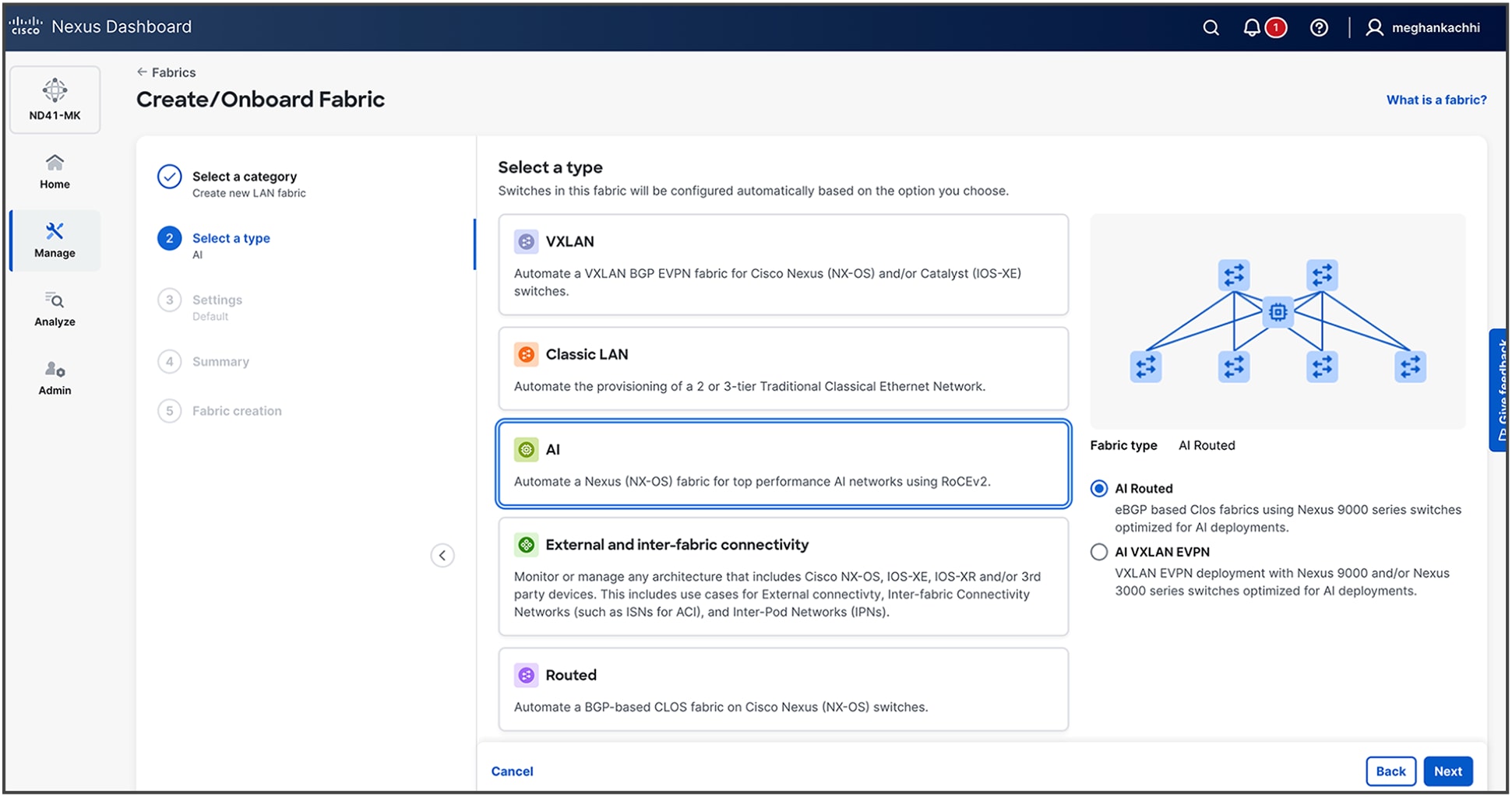
2. Select type as AI (For this example, we are selecting AI Routed.)
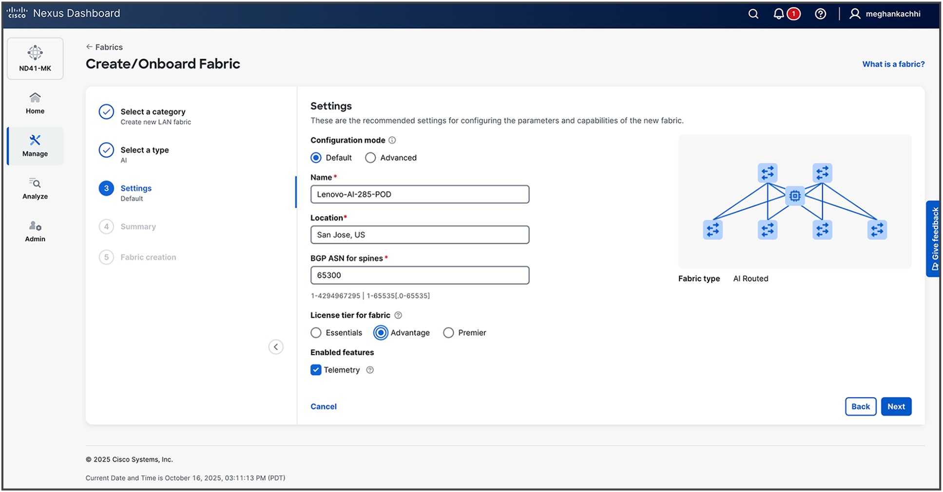
3. Provide details for your fabric. Default configurations are based on best practices as described in previous CLI-based steps. For more advanced settings, you can proceed with Advanced configuration steps.
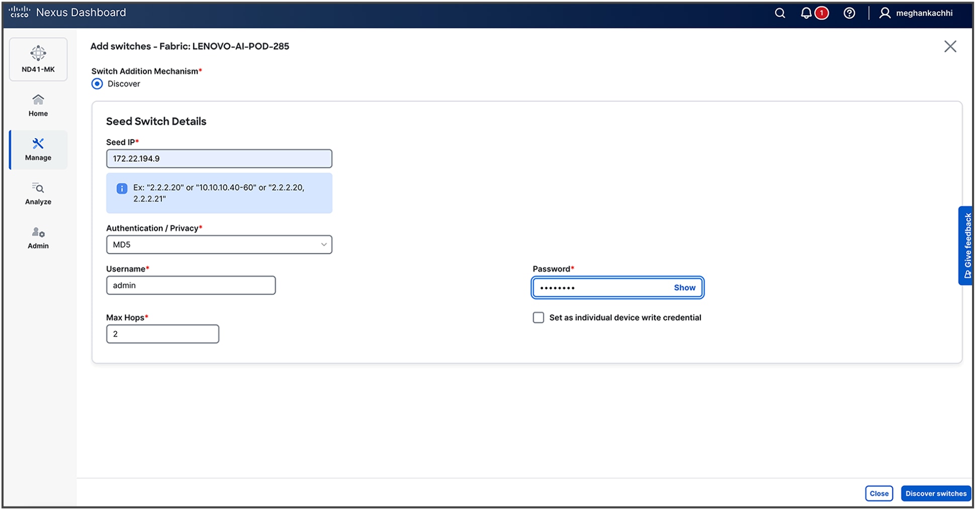
4. Upon fabric creation, the subsequent phase is the onboarding of the network switches. This process is initiated by providing Nexus Dashboard with a seed switch's IP address and administrative credentials. Nexus Dashboard then leverages the Cisco Discovery Protocol (CDP) to recursively discover all interconnected devices, automatically building out the fabric topology based on physical adjacencies.
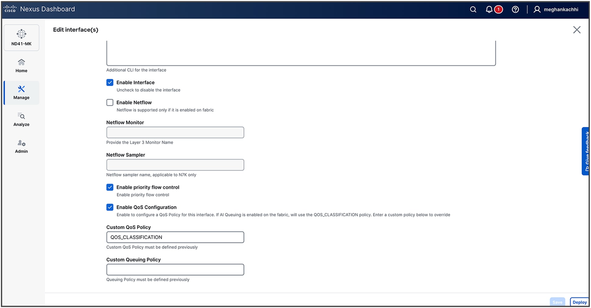
5. Once the fabric is built, edit the interfaces under the Connectivity Tab to Enable Priority Flow Control and Enable QoS configuration along with entering a custom QoS policy (for example, QOS_CLASSIFICATION).
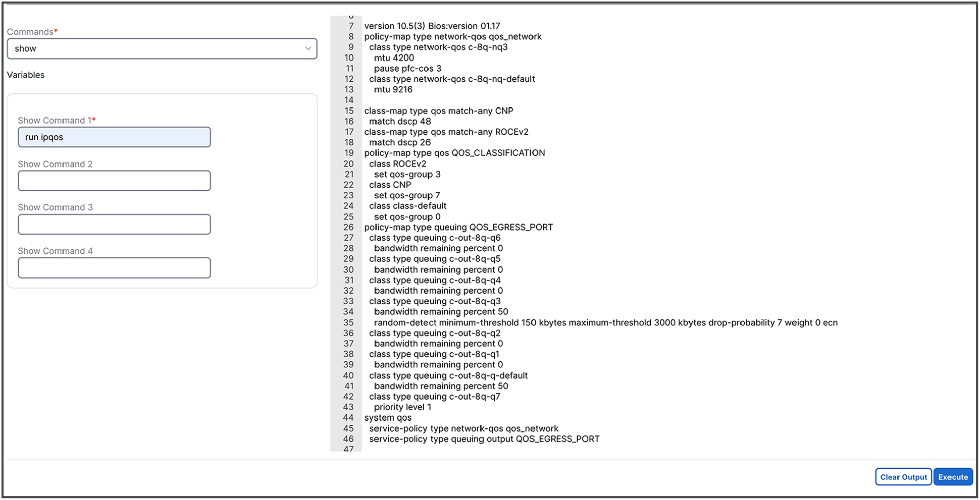
6. Verify the configurations by selecting one of the switches in Inventory, clicking on Actions -> Maintenance -> Show Commands
7. To diagnose a network congestion event identified by an anomaly (if or when it is present in your network), follow the procedures given below to analyze detailed interface-level statistics.
a. Navigate to the affected interface: From the Network Congestion Indication anomaly alert, select the hyperlink for the specific leaf switch and interface that triggered the event. This will take you to the detailed monitoring page for that interface.
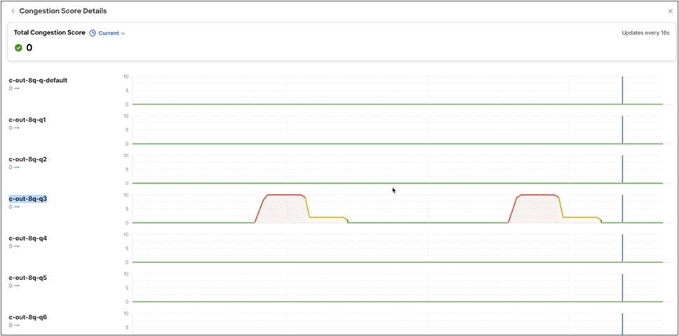
b. Locate congestion metrics: On the interface details page, scroll to the Congestion Score and Congestion Details graphs. These sections provide a visual representation and statistical breakdown of congestion-related events.
c. Analyze congestion counters: The Congestion Details section displays key performance indicators essential for root-cause analysis. Examine the reported values for:
i. WRED/AFD/drops: metrics related to proactive queue management and packet drops
ii. PFC (priority flow control): counters for pause frames, indicating lossless traffic behavior
iii. ECN (explicit congestion notification): statistics for packets marked for congestion notification
d. Perform per-queue investigation: For a more granular diagnosis, select the View Queues link located next to each counter. This action provides a detailed breakdown of statistics at the individual hardware queue level, enabling precise identification of the source of congestion.
RDMA/IB performance test for network performance validation
To validate the performance of RoCEv2 for direct communication between GPUs, Cisco employed the RDMA/InfiniBand (IB) performance benchmark suite: https://github.com/linux-rdma/perftest. The tests were designed to confirm that the underlying lossless network and routing protocols were configured correctly and that the end-to-end connections were stable enough to support traffic at a full 100 percent line-rate.
You can download the suite using the github link and follow steps for installation on your servers. After successful installation, run the following commands for performance validation:
Server-1:
numactl --cpunodebind=0 --membind=0 ib_write_bw -a -d mlx5_1 --report_gbits -q 16
This command is composed of several key parts. The numactl portion is a critical performance tuning step that pins the test process and its memory to a specific CPU socket (NUMA node 0), preventing latency spikes that can occur when accessing memory across different CPUs. The ib_write_bw command itself is the executable for the InfiniBand Write Bandwidth test; when run without an IP address, it defaults to server mode.
The parameters modify the test's behavior:
● -a: runs the test across all available message sizes to provide a comprehensive performance profile
● -d mlx5_1: specifies the RDMA-capable network device to use, in this case, the second Mellanox/NVIDIA adapter found by the system (mlx5_1)
● --report_gbits: changes the output unit from the default Megabytes Per Second (MB/s) to the more network-centric Gigabits per second (Gbps)
● -q 16: sets the number of Queue Pairs (QPs) to 16. Using multiple QPs enables parallel data transfers, which is necessary to saturate high-speed links.
Server-2
numactl --cpunodebind=0 --membind=0 ib_write_bw 192.168.101.25 -a -d mlx5_1 --report_gbits -q 16
This command is nearly identical to the server command, ensuring a consistent test environment on both ends. The one crucial difference is the inclusion of the server's IP address.
● 192.168.101.25: This IP address tells ib_write_bw to operate in client mode and specifies the target server to connect to.
● All other parameters (numactl, -a, -d mlx5_1, --report_gbits, and -q 16) function exactly as they do on the server side, ensuring that both nodes are using the same NUMA policy, device, and test configuration.
In practice, you first run the server command on one machine. It will indicate that it is listening for a connection. You then run the client command on the second machine. The test will execute automatically, and the bandwidth results will be printed to the console on the client side upon completion.
Output:
Server-1
************************************
* Waiting for client to connect... *
************************************
---------------------------------------------------------------------------------------
RDMA_Write BW Test
Dual-port : OFF Device : mlx5_1
Number of qps : 16 Transport type : IB
Connection type : RC Using SRQ : OFF
PCIe relax order: ON Lock-free : OFF
ibv_wr* API : ON Using DDP : OFF
CQ Moderation : 100
CQE Poll Batch : 16
Mtu : 4096[B]
Link type : Ethernet
GID index : 3
Max inline data : 0[B]
rdma_cm QPs : OFF
Data ex. method : Ethernet
---------------------------------------------------------------------------------------
local address: LID 0000 QPN 0x07c5 PSN 0xf04146 RKey 0x203d00 VAddr 0x007fffefac3000
GID: 00:00:00:00:00:00:00:00:00:00:255:255:01:01:101:25
local address: LID 0000 QPN 0x07c6 PSN 0x4018b8 RKey 0x203d00 VAddr 0x007ffff02c3000
GID: 00:00:00:00:00:00:00:00:00:00:255:255:01:01:101:25
local address: LID 0000 QPN 0x07c7 PSN 0x9157a2 RKey 0x203d00 VAddr 0x007ffff0ac3000
GID: 00:00:00:00:00:00:00:00:00:00:255:255:01:01:101:25
local address: LID 0000 QPN 0x07c8 PSN 0x1c7b49 RKey 0x203d00 VAddr 0x007ffff12c3000
GID: 00:00:00:00:00:00:00:00:00:00:255:255:01:01:101:25
local address: LID 0000 QPN 0x07c9 PSN 0xa1ca28 RKey 0x203d00 VAddr 0x007ffff1ac3000
GID: 00:00:00:00:00:00:00:00:00:00:255:255:01:01:101:25
local address: LID 0000 QPN 0x07ca PSN 0xfb586a RKey 0x203d00 VAddr 0x007ffff22c3000
GID: 00:00:00:00:00:00:00:00:00:00:255:255:01:01:101:25
local address: LID 0000 QPN 0x07cb PSN 0x15a281 RKey 0x203d00 VAddr 0x007ffff2ac3000
GID: 00:00:00:00:00:00:00:00:00:00:255:255:01:01:101:25
local address: LID 0000 QPN 0x07cc PSN 0xe752e6 RKey 0x203d00 VAddr 0x007ffff32c3000
GID: 00:00:00:00:00:00:00:00:00:00:255:255:01:01:101:25
local address: LID 0000 QPN 0x07cd PSN 0xcfc992 RKey 0x203d00 VAddr 0x007ffff3ac3000
GID: 00:00:00:00:00:00:00:00:00:00:255:255:01:01:101:25
local address: LID 0000 QPN 0x07ce PSN 0xf07cac RKey 0x203d00 VAddr 0x007ffff42c3000
GID: 00:00:00:00:00:00:00:00:00:00:255:255:01:01:101:25
local address: LID 0000 QPN 0x07cf PSN 0x8d2e0 RKey 0x203d00 VAddr 0x007ffff4ac3000
GID: 00:00:00:00:00:00:00:00:00:00:255:255:01:01:101:25
local address: LID 0000 QPN 0x07d0 PSN 0xf1c9f3 RKey 0x203d00 VAddr 0x007ffff52c3000
GID: 00:00:00:00:00:00:00:00:00:00:255:255:01:01:101:25
local address: LID 0000 QPN 0x07d1 PSN 0x703c63 RKey 0x203d00 VAddr 0x007ffff5ac3000
GID: 00:00:00:00:00:00:00:00:00:00:255:255:01:01:101:25
local address: LID 0000 QPN 0x07d2 PSN 0x9a91d4 RKey 0x203d00 VAddr 0x007ffff62c3000
GID: 00:00:00:00:00:00:00:00:00:00:255:255:01:01:101:25
local address: LID 0000 QPN 0x07d3 PSN 0xc41402 RKey 0x203d00 VAddr 0x007ffff6ac3000
GID: 00:00:00:00:00:00:00:00:00:00:255:255:01:01:101:25
local address: LID 0000 QPN 0x07d4 PSN 0x98209e RKey 0x203d00 VAddr 0x007ffff72c3000
GID: 00:00:00:00:00:00:00:00:00:00:255:255:01:01:101:25
remote address: LID 0000 QPN 0x0871 PSN 0x2be139 RKey 0x1fff00 VAddr 0x007fffefa26000
GID: 00:00:00:00:00:00:00:00:00:00:255:255:01:01:201:25
remote address: LID 0000 QPN 0x0872 PSN 0xd1f866 RKey 0x1fff00 VAddr 0x007ffff0226000
GID: 00:00:00:00:00:00:00:00:00:00:255:255:01:01:201:25
remote address: LID 0000 QPN 0x0873 PSN 0x957582 RKey 0x1fff00 VAddr 0x007ffff0a26000
GID: 00:00:00:00:00:00:00:00:00:00:255:255:01:01:201:25
remote address: LID 0000 QPN 0x0874 PSN 0xbe0072 RKey 0x1fff00 VAddr 0x007ffff1226000
GID: 00:00:00:00:00:00:00:00:00:00:255:255:01:01:201:25
remote address: LID 0000 QPN 0x0875 PSN 0x4cc5d4 RKey 0x1fff00 VAddr 0x007ffff1a26000
GID: 00:00:00:00:00:00:00:00:00:00:255:255:01:01:201:25
remote address: LID 0000 QPN 0x0876 PSN 0xfe9570 RKey 0x1fff00 VAddr 0x007ffff2226000
GID: 00:00:00:00:00:00:00:00:00:00:255:255:01:01:201:25
remote address: LID 0000 QPN 0x0877 PSN 0x5b8ed9 RKey 0x1fff00 VAddr 0x007ffff2a26000
GID: 00:00:00:00:00:00:00:00:00:00:255:255:01:01:201:25
remote address: LID 0000 QPN 0x0878 PSN 0xad9128 RKey 0x1fff00 VAddr 0x007ffff3226000
GID: 00:00:00:00:00:00:00:00:00:00:255:255:01:01:201:25
remote address: LID 0000 QPN 0x0879 PSN 0x892476 RKey 0x1fff00 VAddr 0x007ffff3a26000
GID: 00:00:00:00:00:00:00:00:00:00:255:255:01:01:201:25
remote address: LID 0000 QPN 0x087a PSN 0x3e9489 RKey 0x1fff00 VAddr 0x007ffff4226000
GID: 00:00:00:00:00:00:00:00:00:00:255:255:01:01:201:25
remote address: LID 0000 QPN 0x087b PSN 0xebfd2f RKey 0x1fff00 VAddr 0x007ffff4a26000
GID: 00:00:00:00:00:00:00:00:00:00:255:255:01:01:201:25
remote address: LID 0000 QPN 0x087c PSN 0xf83acd RKey 0x1fff00 VAddr 0x007ffff5226000
GID: 00:00:00:00:00:00:00:00:00:00:255:255:01:01:201:25
remote address: LID 0000 QPN 0x087d PSN 0x13b1ff RKey 0x1fff00 VAddr 0x007ffff5a26000
GID: 00:00:00:00:00:00:00:00:00:00:255:255:01:01:201:25
remote address: LID 0000 QPN 0x087e PSN 0x375a09 RKey 0x1fff00 VAddr 0x007ffff6226000
GID: 00:00:00:00:00:00:00:00:00:00:255:255:01:01:201:25
remote address: LID 0000 QPN 0x087f PSN 0xb763c9 RKey 0x1fff00 VAddr 0x007ffff6a26000
GID: 00:00:00:00:00:00:00:00:00:00:255:255:01:01:201:25
remote address: LID 0000 QPN 0x0880 PSN 0xc8558f RKey 0x1fff00 VAddr 0x007ffff7226000
GID: 00:00:00:00:00:00:00:00:00:00:255:255:01:01:201:25
---------------------------------------------------------------------------------------
#bytes #iterations BW peak[Gb/sec] BW average[Gb/sec] MsgRate[Mpps]
8388608 80000 391.53 391.53 0.005834
---------------------------------------------------------------------------------------
Server-2
---------------------------------------------------------------------------------------
RDMA_Write BW Test
Dual-port : OFF Device : mlx5_1
Number of qps : 16 Transport type : IB
Connection type : RC Using SRQ : OFF
PCIe relax order: ON Lock-free : OFF
ibv_wr* API : ON Using DDP : OFF
TX depth : 128
CQ Moderation : 100
CQE Poll Batch : 16
Mtu : 4096[B]
Link type : Ethernet
GID index : 3
Max inline data : 0[B]
rdma_cm QPs : OFF
Data ex. method : Ethernet
---------------------------------------------------------------------------------------
local address: LID 0000 QPN 0x0871 PSN 0x2be139 RKey 0x1fff00 VAddr 0x007fffefa26000
GID: 00:00:00:00:00:00:00:00:00:00:255:255:01:01:201:25
local address: LID 0000 QPN 0x0872 PSN 0xd1f866 RKey 0x1fff00 VAddr 0x007ffff0226000
GID: 00:00:00:00:00:00:00:00:00:00:255:255:01:01:201:25
local address: LID 0000 QPN 0x0873 PSN 0x957582 RKey 0x1fff00 VAddr 0x007ffff0a26000
GID: 00:00:00:00:00:00:00:00:00:00:255:255:01:01:201:25
local address: LID 0000 QPN 0x0874 PSN 0xbe0072 RKey 0x1fff00 VAddr 0x007ffff1226000
GID: 00:00:00:00:00:00:00:00:00:00:255:255:01:01:201:25
local address: LID 0000 QPN 0x0875 PSN 0x4cc5d4 RKey 0x1fff00 VAddr 0x007ffff1a26000
GID: 00:00:00:00:00:00:00:00:00:00:255:255:01:01:201:25
local address: LID 0000 QPN 0x0876 PSN 0xfe9570 RKey 0x1fff00 VAddr 0x007ffff2226000
GID: 00:00:00:00:00:00:00:00:00:00:255:255:01:01:201:25
local address: LID 0000 QPN 0x0877 PSN 0x5b8ed9 RKey 0x1fff00 VAddr 0x007ffff2a26000
GID: 00:00:00:00:00:00:00:00:00:00:255:255:01:01:201:25
local address: LID 0000 QPN 0x0878 PSN 0xad9128 RKey 0x1fff00 VAddr 0x007ffff3226000
GID: 00:00:00:00:00:00:00:00:00:00:255:255:01:01:201:25
local address: LID 0000 QPN 0x0879 PSN 0x892476 RKey 0x1fff00 VAddr 0x007ffff3a26000
GID: 00:00:00:00:00:00:00:00:00:00:255:255:01:01:201:25
local address: LID 0000 QPN 0x087a PSN 0x3e9489 RKey 0x1fff00 VAddr 0x007ffff4226000
GID: 00:00:00:00:00:00:00:00:00:00:255:255:01:01:201:25
local address: LID 0000 QPN 0x087b PSN 0xebfd2f RKey 0x1fff00 VAddr 0x007ffff4a26000
GID: 00:00:00:00:00:00:00:00:00:00:255:255:01:01:201:25
local address: LID 0000 QPN 0x087c PSN 0xf83acd RKey 0x1fff00 VAddr 0x007ffff5226000
GID: 00:00:00:00:00:00:00:00:00:00:255:255:01:01:201:25
local address: LID 0000 QPN 0x087d PSN 0x13b1ff RKey 0x1fff00 VAddr 0x007ffff5a26000
GID: 00:00:00:00:00:00:00:00:00:00:255:255:01:01:201:25
local address: LID 0000 QPN 0x087e PSN 0x375a09 RKey 0x1fff00 VAddr 0x007ffff6226000
GID: 00:00:00:00:00:00:00:00:00:00:255:255:01:01:201:25
local address: LID 0000 QPN 0x087f PSN 0xb763c9 RKey 0x1fff00 VAddr 0x007ffff6a26000
GID: 00:00:00:00:00:00:00:00:00:00:255:255:01:01:201:25
local address: LID 0000 QPN 0x0880 PSN 0xc8558f RKey 0x1fff00 VAddr 0x007ffff7226000
GID: 00:00:00:00:00:00:00:00:00:00:255:255:01:01:201:25
remote address: LID 0000 QPN 0x07c5 PSN 0xf04146 RKey 0x203d00 VAddr 0x007fffefac3000
GID: 00:00:00:00:00:00:00:00:00:00:255:255:01:01:101:25
remote address: LID 0000 QPN 0x07c6 PSN 0x4018b8 RKey 0x203d00 VAddr 0x007ffff02c3000
GID: 00:00:00:00:00:00:00:00:00:00:255:255:01:01:101:25
remote address: LID 0000 QPN 0x07c7 PSN 0x9157a2 RKey 0x203d00 VAddr 0x007ffff0ac3000
GID: 00:00:00:00:00:00:00:00:00:00:255:255:01:01:101:25
remote address: LID 0000 QPN 0x07c8 PSN 0x1c7b49 RKey 0x203d00 VAddr 0x007ffff12c3000
GID: 00:00:00:00:00:00:00:00:00:00:255:255:01:01:101:25
remote address: LID 0000 QPN 0x07c9 PSN 0xa1ca28 RKey 0x203d00 VAddr 0x007ffff1ac3000
GID: 00:00:00:00:00:00:00:00:00:00:255:255:01:01:101:25
remote address: LID 0000 QPN 0x07ca PSN 0xfb586a RKey 0x203d00 VAddr 0x007ffff22c3000
GID: 00:00:00:00:00:00:00:00:00:00:255:255:01:01:101:25
remote address: LID 0000 QPN 0x07cb PSN 0x15a281 RKey 0x203d00 VAddr 0x007ffff2ac3000
GID: 00:00:00:00:00:00:00:00:00:00:255:255:01:01:101:25
remote address: LID 0000 QPN 0x07cc PSN 0xe752e6 RKey 0x203d00 VAddr 0x007ffff32c3000
GID: 00:00:00:00:00:00:00:00:00:00:255:255:01:01:101:25
remote address: LID 0000 QPN 0x07cd PSN 0xcfc992 RKey 0x203d00 VAddr 0x007ffff3ac3000
GID: 00:00:00:00:00:00:00:00:00:00:255:255:01:01:101:25
remote address: LID 0000 QPN 0x07ce PSN 0xf07cac RKey 0x203d00 VAddr 0x007ffff42c3000
GID: 00:00:00:00:00:00:00:00:00:00:255:255:01:01:101:25
remote address: LID 0000 QPN 0x07cf PSN 0x8d2e0 RKey 0x203d00 VAddr 0x007ffff4ac3000
GID: 00:00:00:00:00:00:00:00:00:00:255:255:01:01:101:25
remote address: LID 0000 QPN 0x07d0 PSN 0xf1c9f3 RKey 0x203d00 VAddr 0x007ffff52c3000
GID: 00:00:00:00:00:00:00:00:00:00:255:255:01:01:101:25
remote address: LID 0000 QPN 0x07d1 PSN 0x703c63 RKey 0x203d00 VAddr 0x007ffff5ac3000
GID: 00:00:00:00:00:00:00:00:00:00:255:255:01:01:101:25
remote address: LID 0000 QPN 0x07d2 PSN 0x9a91d4 RKey 0x203d00 VAddr 0x007ffff62c3000
GID: 00:00:00:00:00:00:00:00:00:00:255:255:01:01:101:25
remote address: LID 0000 QPN 0x07d3 PSN 0xc41402 RKey 0x203d00 VAddr 0x007ffff6ac3000
GID: 00:00:00:00:00:00:00:00:00:00:255:255:01:01:101:25
remote address: LID 0000 QPN 0x07d4 PSN 0x98209e RKey 0x203d00 VAddr 0x007ffff72c3000
GID: 00:00:00:00:00:00:00:00:00:00:255:255:01:01:101:25
---------------------------------------------------------------------------------------
#bytes #iterations BW peak[Gb/sec] BW average[Gb/sec] MsgRate[Mpps]
2 80000 0.095617 0.095542 5.971350
4 80000 0.19 0.19 6.043600
8 80000 0.39 0.39 6.057085
16 80000 0.77 0.77 6.029973
32 80000 1.56 1.55 6.067049
64 80000 3.11 3.11 6.069521
128 80000 6.18 6.18 6.031414
256 80000 12.36 12.36 6.033941
512 80000 24.72 24.67 6.022545
1024 80000 49.33 49.29 6.016425
2048 80000 98.16 98.06 5.985260
4096 80000 194.37 25.64 0.782418
8192 80000 381.19 54.09 0.825285
16384 80000 376.17 108.07 0.824473
32768 80000 382.82 270.39 1.031458
65536 80000 386.12 372.57 0.710622
131072 80000 388.62 355.34 0.338879
262144 80000 390.25 390.22 0.186074
524288 80000 391.65 391.63 0.093373
1048576 80000 391.96 391.95 0.046724
2097152 80000 392.09 392.09 0.023370
4194304 80000 391.67 391.67 0.011673
8388608 80000 391.53 391.53 0.005834
---------------------------------------------------------------------------------------
We leverage the ib_write_bw benchmark to assess RoCEv2 throughput for inter-GPU workloads, confirming the health and proper configuration of the lossless network fabric. The tests verified that the end-to-end paths on a Cisco Nexus 9364D-GX2A switch could sustain 100 percent line-rate traffic. The measured average bandwidth of 391 Gbps on a 400 Gbps link represents the maximum achievable goodput after taking the encapsulation overhead of the RoCEv2 protocol headers into consideration.
Verify end-end QoS on Cisco Nexus 9300 switch for RDMA traffic
You should verify QOS Group 3 numbers TX packets incrementing for all test runs, which makes sure the right treatment is given for AI traffic.
Nexus-9364D-GX2A-1# sh queuing interface et1/1
slot 1
=======
Egress Queuing for Ethernet1/1 [System]
-------------------------------------------------------------------------------
QoS-Group# Bandwidth%% PrioLevel Shape QLimit
Min Max Units
-------------------------------------------------------------------------------
7 - 1 - - - 9(D)
6 0 - - - - 9(D)
5 0 - - - - 9(D)
4 0 - - - - 9(D)
3 99 - - - - (N/A)
2 0 - - - - 9(D)
1 0 - - - - 9(D)
0 1 - - - - 9(D)
+-------------------------------------------------------------+
| QOS GROUP 0 |
+-------------------------------------------------------------+
| | Unicast |Multicast |
+-------------------------------------------------------------+
| Tx Pkts | 1959| 0|
| Tx Byts | 257502| 0|
| WRED/AFD & Tail Drop Pkts | 0| 0|
| WRED/AFD & Tail Drop Byts | 0| 0|
| ECN Pkts | 0| 0|
| ECN Byts | 0| 0|
| Q Depth Byts | 0| 0|
+-------------------------------------------------------------+
| QOS GROUP 1 |
+-------------------------------------------------------------+
| | Unicast |Multicast |
+-------------------------------------------------------------+
| Tx Pkts | 0| 0|
| Tx Byts | 0| 0|
| WRED/AFD & Tail Drop Pkts | 0| 0|
| WRED/AFD & Tail Drop Byts | 0| 0|
| ECN Pkts | 0| 0|
| ECN Byts | 0| 0|
| Q Depth Byts | 0| 0|
+-------------------------------------------------------------+
| QOS GROUP 2 |
+-------------------------------------------------------------+
| | Unicast |Multicast |
+-------------------------------------------------------------+
| Tx Pkts | 0| 0|
| Tx Byts | 0| 0|
| WRED/AFD & Tail Drop Pkts | 0| 0|
| WRED/AFD & Tail Drop Byts | 0| 0|
| ECN Pkts | 0| 0|
| ECN Byts | 0| 0|
| Q Depth Byts | 0| 0|
+-------------------------------------------------------------+
|
| QOS GROUP 3 | +-------------------------------------------------------------+ | | Unicast |Multicast | +-------------------------------------------------------------+ | Tx Pkts | 85923028| 0| | Tx Byts | 343892489604| 0| | WRED/AFD & Tail Drop Pkts | 0| 0| | WRED/AFD & Tail Drop Byts | 0| 0| | ECN Pkts | 0| 0| | ECN Byts | 0| 0| | Q Depth Byts | 0| 0| |
+-------------------------------------------------------------+
| QOS GROUP 4 |
+-------------------------------------------------------------+
| | Unicast |Multicast |
+-------------------------------------------------------------+
| Tx Pkts | 0| 0|
| Tx Byts | 0| 0|
| WRED/AFD & Tail Drop Pkts | 0| 0|
| WRED/AFD & Tail Drop Byts | 0| 0|
| ECN Pkts | 0| 0|
| ECN Byts | 0| 0|
| Q Depth Byts | 0| 0|
+-------------------------------------------------------------+
| QOS GROUP 5 |
+-------------------------------------------------------------+
| | Unicast |Multicast |
+-------------------------------------------------------------+
| Tx Pkts | 0| 0|
| Tx Byts | 0| 0|
| WRED/AFD & Tail Drop Pkts | 0| 0|
| WRED/AFD & Tail Drop Byts | 0| 0|
| ECN Pkts | 0| 0|
| ECN Byts | 0| 0|
| Q Depth Byts | 0| 0|
+-------------------------------------------------------------+
| QOS GROUP 6 |
+-------------------------------------------------------------+
| | Unicast |Multicast |
+-------------------------------------------------------------+
| Tx Pkts | 0| 0|
| Tx Byts | 0| 0|
| WRED/AFD & Tail Drop Pkts | 0| 0|
| WRED/AFD & Tail Drop Byts | 0| 0|
| ECN Pkts | 0| 0|
| ECN Byts | 0| 0|
| Q Depth Byts | 0| 0|
+-------------------------------------------------------------+
| QOS GROUP 7 |
+-------------------------------------------------------------+
| | Unicast |Multicast |
+-------------------------------------------------------------+
| Tx Pkts | 0| 0|
| Tx Byts | 0| 0|
| WRED/AFD & Tail Drop Pkts | 0| 0|
| WRED/AFD & Tail Drop Byts | 0| 0|
| ECN Pkts | 0| 0|
| ECN Byts | 0| 0|
| Q Depth Byts | 0| 0|
+-------------------------------------------------------------+
| CONTROL QOS GROUP |
+-------------------------------------------------------------+
| Tx Pkts | 162940| 0|
| Tx Byts | 53055304| 0|
| WRED/AFD & Tail Drop Pkts | 0| 0|
| WRED/AFD & Tail Drop Byts | 0| 0|
+-------------------------------------------------------------+
| SPAN QOS GROUP |
+-------------------------------------------------------------+
| Tx Pkts | 0| 0|
| Tx Byts | 0| 0|
| WRED/AFD & Tail Drop Pkts | 0| 0|
| WRED/AFD & Tail Drop Byts | 0| 0|
Per Slice Egress SPAN Statistics
---------------------------------------------------------------
SPAN Copies Tail Drop Pkts 0
SPAN Input Queue Drop Pkts 0
SPAN Copies/Transit Tail Drop Pkts 0
SPAN Input Desc Drop Pkts 0
Ingress Queuing for Ethernet1/1
--------------------------------------------------------
QoS-Group# Pause
Buff Size Pause Th Resume Th
--------------------------------------------------------
7 - - -
6 - - -
5 - - -
4 - - -
3 1114176 584832 580800
2 - - -
1 - - -
0 - - -
Per Port Ingress Statistics
--------------------------------------------------------
Hi Priority Drop Pkts 0
Low Priority Drop Pkts 0
Ingress Overflow Drop Statistics
--------------------------------------------------------
All Pause Drop Pkts 0
High Pause Drop Pkts 0
Low Pause Drop Pkts 0
PFC Statistics
------------------------------------------------------------------------------
TxPPP: 0, RxPPP: 0
------------------------------------------------------------------------------
PFC_COS QOS_Group TxPause TxCount RxPause RxCount
0 - Inactive 0 Inactive 0
1 - Inactive 0 Inactive 0
2 - Inactive 0 Inactive 0
3 3 Inactive 0 Inactive 0
4 - Inactive 0 Inactive 0
5 - Inactive 0 Inactive 0
6 - Inactive 0 Inactive 0
7 - Inactive 0 Inactive 0
------------------------------------------------------------------------------
This validated design provides a comprehensive blueprint for deploying a high-performance, scalable AI infrastructure by combining Lenovo's powerful ThinkSystem SR675 V3 compute nodes with Cisco's robust Nexus networking fabric. By following the detailed steps for server tuning, software stack deployment, and lossless network configuration, enterprises can build a reliable foundation for demanding AI/ML workloads. The guide demonstrates two powerful methods for fabric configuration: a granular CLI approach using the Cisco Modular Quality of Service framework and an automated, template-driven process using Cisco Nexus Dashboard. Performance validation using the ib_write_bw benchmark confirms the success of the configuration, achieving an impressive 391 Gbps of goodput on a 400 Gbps link. This shows that the end-to-end architecture is correctly tuned to prevent packet loss and maximize throughput for RoCEv2 traffic. Ultimately, this guide empowers organizations to accelerate their AI initiatives, providing a clear path from a starter kit to a multi-rack, production-grade AI factory.
| Part number |
Product description |
Qty |
| 7D9RCTO1WW |
Server: Lenovo ThinkSystem SR675 V3 3yr Warranty with Controlled GPU |
2 |
| BR7F |
Lenovo ThinkSystem SR675 V3 8DW PCIe GPU Base |
2 |
| C2AL |
Lenovo ThinkSystem AMD EPYC 9535 64C 300W 2.4GHz Processor |
4 |
| C0CK |
Lenovo ThinkSystem 64GB TruDDR5 6400MHz (2Rx4) RDIMM-A |
48 |
| C1AE |
Lenovo ThinkSystem E3.S PM9D3a 3.84TB Read Intensive NVMe PCIe 5.0 x4 HS SSD |
4 |
| BTMB |
Lenovo ThinkSystem 1x4 E3.S Backplane |
2 |
| B8P9 |
Lenovo ThinkSystem M.2 NVMe 2-Bay RAID Adapter |
2 |
| BXMH |
Lenovo ThinkSystem M.2 PM9A3 960GB Read Intensive NVMe PCIe 4.0 x4 NHS SSD |
4 |
| C0Q4 |
Lenovo ThinkSystem NVIDIA BlueField-3 B3140H VPI QSFP112 1P 400G PCIe Gen5 x16 Adapter |
8 |
| BVBG |
Lenovo ThinkSystem NVIDIA BlueField-3 B3220 VPI QSFP112 2P 200G PCIe Gen5 x16 Adapter |
2 |
| BYFH |
Lenovo ThinkSystem NVIDIA L40S 48GB PCIe Gen4 Passive GPU |
8 |
| BR7L |
Lenovo ThinkSystem SR675 V3 x16/x16 PCIe Riser Option Kit |
4 |
| BR7H |
Lenovo ThinkSystem SR675 V3 2x16 PCIe Front IO Riser |
2 |
| BR7S |
Lenovo ThinkSystem SR675 V3 Switched 4x16 PCIe DW GPU Direct RDMA Riser |
4 |
| BKTJ |
Lenovo ThinkSystem 2600W 230V Titanium Hot-Swap Gen2 Power Supply |
8 |
| 6252 |
2.5m, 16A/100-250V, C19 to C20 Jumper Cord |
8 |
| C3KA |
Lenovo ThinkSystem SR670 V2/SR675 V3 Heavy Systems Toolless Slide Rail Kit |
2 |
| C3EF |
Lenovo ThinkSystem SR675 V3 System Board v2 |
2 |
| BABV |
Lenovo ThinkSystem Screw for fix M.2 Adapter |
2 |
| BR7U |
Lenovo ThinkSystem SR675 V3 Root of Trust Module |
2 |
| BFTH |
Lenovo ThinkSystem SR670 V2/ SR675 V3 Front Operator Panel ASM |
2 |
| BFD6 |
Lenovo ThinkSystem SR670 V2/ SR675 V3 Power Mezzanine Board |
2 |
| C5WW |
Lenovo ThinkSystem SR675 V3 Dual Rotor System High Performance Fan |
10 |
| BTME |
Lenovo ThinkSystem SR675 V3 E3.S Backplane Cage Assembly for 8DW PCIe GPU Base |
2 |
| 5641PX3 |
Lenovo XClarity Pro, Per Endpoint w/3 Yr SW S&S |
2 |
| 1340 |
Lenovo XClarity Pro, Per Managed Endpoint w/3 Yr SW S&S |
2 |
| 7Q01CTSAWW |
SERVER KEEP YOUR DRIVE ADD-ON |
2 |
| 7Q01CTS4WW |
SERVER PREMIER 24X7 4HR RESP |
2 |
| Part Number |
Description |
Qty |
| 7D9GCTO1WW |
Server: Lenovo ThinkSystem SR635 V3 - 3yr Warranty |
|
| BLK4 |
Lenovo ThinkSystem V3 1U 10x2.5" Chassis |
1 |
| BVGL |
Data Center Environment 30 Degree Celsius / 86 Degree Fahrenheit |
1 |
| C2AQ |
Lenovo ThinkSystem AMD EPYC 9335 32C 210W 3.0GHz Processor |
1 |
| BQ26 |
Lenovo ThinkSystem SR645 V3/SR635 V3 1U High Performance Heatsink |
1 |
| C1PL |
Lenovo ThinkSystem 32GB TruDDR5 6400MHz (1Rx4) RDIMM-A |
12 |
| BC4V |
Non RAID NVMe |
1 |
| C0ZU |
Lenovo ThinkSystem 2.5" U.2 VA 3.84TB Read Intensive NVMe PCIe 5.0 x4 HS SSD |
2 |
| BPC9 |
Lenovo ThinkSystem 1U 4x 2.5" NVMe Gen 4 Backplane |
1 |
| B5XJ |
Lenovo ThinkSystem M.2 SATA/NVMe 2-Bay Adapter |
1 |
| BTTY |
M.2 NVMe |
1 |
| BKSR |
Lenovo ThinkSystem M.2 7450 PRO 960GB Read Intensive NVMe PCIe 4.0 x4 NHS SSD |
2 |
| BQBN |
Lenovo ThinkSystem NVIDIA ConnectX-7 NDR200/200GbE QSFP112 2-port PCIe Gen5 x16 Adapter |
1 |
| BLK7 |
Lenovo ThinkSystem SR635 V3/SR645 V3 x16 PCIe Gen5 Riser 1 |
1 |
| BLK9 |
Lenovo ThinkSystem V3 1U MS LP+LP BF Riser Cage |
1 |
| BNFG |
Lenovo ThinkSystem 750W 230V/115V Platinum Hot-Swap Gen2 Power Supply v3 |
2 |
| BH9M |
Lenovo ThinkSystem V3 1U Performance Fan Option Kit v2 |
7 |
| BLKD |
Lenovo ThinkSystem 1U V3 10x2.5" Media Bay w/ Ext. Diagnostics Port |
1 |
| 7Q01CTS2WW |
5Yr Premier NBD Resp + KYD SR635 V3 |
1 |
| Part number |
Description |
Qty |
| 7DLKCTO1WW |
Cisco Nexus 9300-GX2 Series Switch (N9K-C9364D-GX2A) |
|
| C5P0 |
Cisco Nexus 9300-GX2 Series Switch (N9K-C9364D-GX2A) |
2 |
| C6FK |
Mode selection between Cisco ACI® and Cisco NX-OS (MODE-NXOS) |
2 |
| 6252 |
2.5m, 16A/100-250V, C19 to C20 Jumper Cord |
4 |
| C1P1TN9300XF2-5Y |
5 Years (60 months) Cisco® software Premier license |
2 |
| Part number |
Description |
Qty |
| 7DL8CTO1WW |
Cisco Nexus 9300-FX3 Series Switch (N9K-C93108TC-FX3) |
|
| C5PB |
Cisco Nexus 9300-GX2 Series Switch (N9K-C9364D-GX2A) |
2 |
| C6FK |
Mode selection between ACI and NXOS (MODE-NXOS) |
2 |
| 6252 |
2.5m, 16A/100-250V, C19 to C20 Jumper Cord |
4 |
| C1P1TN9300XF-5Y |
5 Years (60 months) Cisco software Premier license |
2 |
The product guide and configurator tool can be found here:
https://lenovopress.lenovo.com/lp2236-lenovo-hybrid-ai-285-with-cisco-networking