5G Enterprise Radio Access Networks White Paper
Available Languages
Bias-Free Language
The documentation set for this product strives to use bias-free language. For the purposes of this documentation set, bias-free is defined as language that does not imply discrimination based on age, disability, gender, racial identity, ethnic identity, sexual orientation, socioeconomic status, and intersectionality. Exceptions may be present in the documentation due to language that is hardcoded in the user interfaces of the product software, language used based on RFP documentation, or language that is used by a referenced third-party product. Learn more about how Cisco is using Inclusive Language.
By 2023, there will be 13.1 billion mobile devices and connections globally (up from 8.8 billion in 2018). Supporting this growth is a new standard, 5G, the next-generation wireless technology designed to connect virtually everyone and everything. 5G inherits the deterministic behavior and proven mobility performance of traditional cellular technologies. It is designed to address the requirements of a wide range of use cases, including high throughput, high reliability, low latency, massive IoT deployments, and vehicle-to-vehicle communications.
Various enhancements supported by the standard make 5G perfectly suitable for emerging enterprise use cases that demand better reliability, wider coverage, and low latency. Extended support in shared and unlicensed spectrum makes 5G even more attractive for enterprises. In addition, 5G operates in new bands up to 60 GHz as well as the legacy spectrum under 6 GHz.
This paper focuses primarily on how enterprises can use 5G-based radio access networks to enable new use cases and also provides a high-level overview of the architectural options available for different types of enterprise deployments.
Technology evolution in addressing enterprise use cases
Traditionally, enterprises have been reliant on Ethernet and Wi-Fi for their connectivity needs. While Ethernet meets their requirements for high throughput, low latency, and reliability, it has only a limited ability to address their device mobility needs. Some enterprises, especially those in the manufacturing sector, need to reconfigure their production lines frequently based on changes in their manufacturing plans. Rewiring Ethernet every time can be a very costly affair. Wi-Fi technology presents a better alternative, addressing some of the drawbacks of Ethernet. However, the Wi-Fi spectrum is prone to interference and reliability challenges.
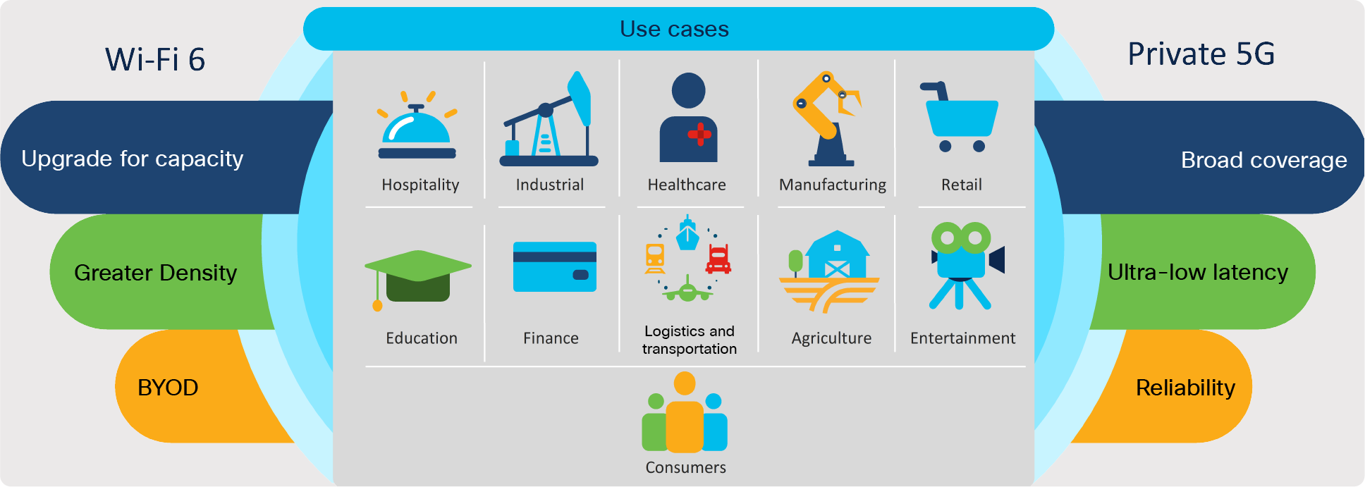
Use cases for the new Wi-Fi 6 and private 5G technologies
As businesses look toward digital transformation, wireless communication is expected to play a key role in enabling the Industry 4.0 systems and technologies. For wireless communication, enterprises now have several choices, from Wi-Fi 6 to 4G/LTE and 5G technologies, each suited to several different use cases and providing complementary services. The enterprise can take advantage of the determinism and reliability of LTE and 5G to address mission-critical applications and extend cellular service to areas with poor coverage.
Wi-Fi 6 and soon Wi-Fi 6E, as well as private 5G, are various technologies that Enterprises can use to digitize their businesses worldwide. These technologies are driven by the need for:
● Higher performance that will be necessary when students go to 4K and 8K video, as they will soon.
● Low latency, 15 milliseconds or less, required for immersive applications such as AR and VR.
● IoT scale that can help customers connect thousands of devices over both Wi-Fi 6 and private 5G. When you have 100 devices in a 100-square-foot area, the interference level can be high. Private cellular networks can help meet tighter Service-Level Agreement (SLA) requirements in addition to higher throughput demands.
● Reliable mobility to enable better process automation. For instance, when to hand over and where to hand over is up to the client. Sticky Wi-Fi client behavior can cause connection drops that lead to Automated Guided Vehicles (AGVs) and robots freezing in the middle of their operation. Private 5G networks can help address some of these limitations, enabling better reliability and augmenting of existing Wi-Fi networks in the enterprise.
Let’s look at what it takes to build a private 5G network in an enterprise.
A 5G network essentially consists of three elements: A packet core, a Radio Access Network (RAN), and User Equipment (UE), as shown in the figure below.
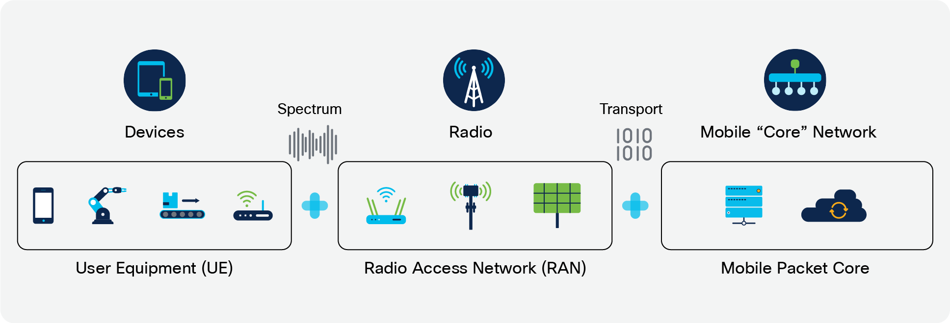
Elements of a 5G network
The mobile packet core consists of the functions shown in blue in Figure 3.
Packet core functions can be grouped into Control Plane Functions (CPF) and User Plane Functions (UPF).
● CPF implements user authentication, mobility management, subscriber management, access policy management, etc.
● UPF is the gateway or entry point for the 5G data. UPF implements routing, classification, and traffic policies for user traffic.
Individual functions of the packet core can be implemented as a single-box solution or as distributed physical nodes. This logical decomposition depends on various factors such as the size of the deployment, scalability, physical location, etc. In general, CPF and UPF can be deployed in different physical locations. CPF can be in a centralized location such as a data center or Network Operations Center (NOC), while UPF can be onsite or in an internet service provider’s point of presence.
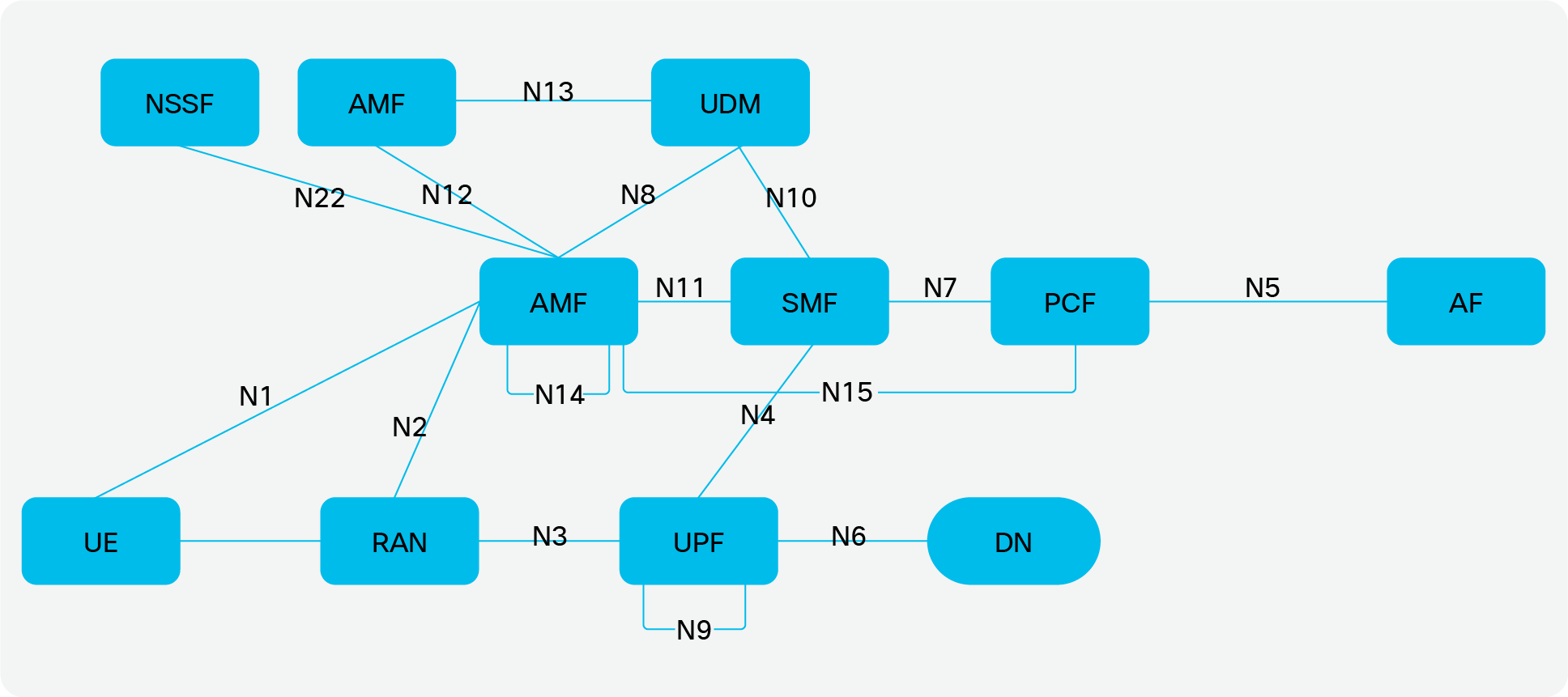
5G network architecture (Source: 3GPP)
RAN is the radio access layer. It implements all of the radio interfaces and call control functions.
UE denotes user equipment and consists of endpoints that connect to the cellular network.
A 5G RAN enables radio access to the client devices. At a high level, a 5G RAN provides the following functionality:
● UE connection management: This includes initial radio access, synchronization between RAN and UE, establishment of the radio connection, and connection maintenance. Once a radio connection is established, the UE will exchange Non-Access Stratum (NAS) signaling with the packet core that may include an authentication procedure, followed by establishment of an end-to-end PDU session (user plane/data).
● Handling of user plane traffic: In 5G, data traffic from the network to UE and from UE to the network enters or exits through the packet core. The packet core classifies the incoming packets and maps them to the corresponding PDU session belonging to the UE. MAC headers are removed, and only the IP datagrams are sent over the GTP-u tunnel established for the PDU session between the packet core and the RAN system. The RAN system takes the IP datagrams and schedules over the radio interface to the user. Unlike Wi-Fi, transmission in 5G RAN is based on fixed time slots (Frequency Division Duplex [FDD] and Time Division Duplex [TDD] to be precise). Control information and user data together are packed in each radio frame. More than one user can be scheduled at the same time in a radio frame, or slot. In order to meet the SLA requirements of individual user sessions, the RAN scheduler implements Quality- of-Service (QoS) scheduling policies. The goal of the scheduler algorithm is to maximize the spectral efficiency of the system while maintaining the QoS requirements of individual sessions.
● Baseband processing: During downlink processing, information scheduled is modulated and mapped to radio resource elements, and then the IQ symbols are generated for each antenna stream. During uplink processing, received IQ symbols are demodulated, control information and the signaling is consumed by the local stack components, and the data is tunneled toward the packet core.
● Radio interface: During the transmission interval, IQ symbols generated by the baseband are converted to the RF signal that is then transmitted over the air. When it is time for reception, the RF signal received from the UE is converted to IQ symbols for baseband processing.
Essentially, 5G RAN consists of the following layers.
Layer 3 protocol stack includes Radio Resource Control (RRC), NG Application Protocol (NGAP), and Xn layers. RRC is responsible for radio resource control, broadcast of system information, and the establishment, maintenance, and release of the UE radio connection. NGAP enables NAS communication between UE and the packet core. Xn enables peer-to-peer communication between two RANs for faster handovers.
Layer 2 protocol stack includes Packet Data Convergence Protocol (PDCP), Radio Link Control (RLC), and MAC sublayers. PDCP is responsible for over-the-air data ciphering, anchoring data during handover, and duplicating data packets over multiple redundant radio access paths for providing reliability. RLC handles over- the-air segmentation/reassembly and retransmissions in case of loss of data over the air. MAC implements scheduler, link adaptation, radio frame management, and Hybrid Automatic Repeat Request (HARQ) for block- level retransmissions.
Physical layer implements the baseband processing functions such as modulation, waveform generation, channel coding, etc. Generated digital samples are sent to the radio module to be transmitted over the air.
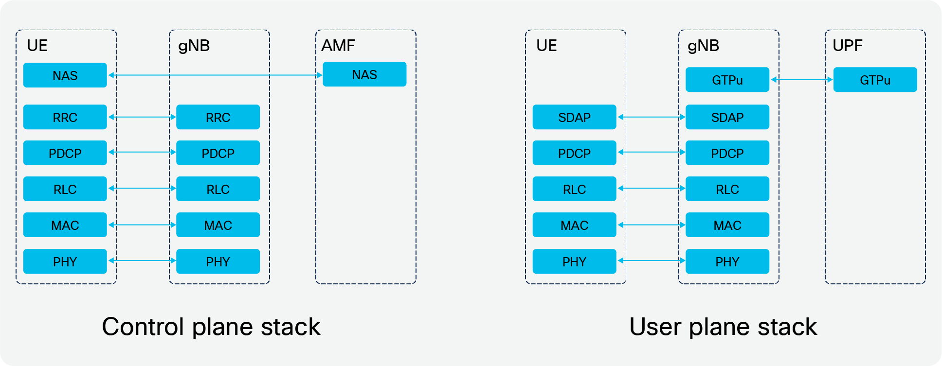
5G access protocol stack layers (Source: 3GPP)
Earlier implementations of cellular systems integrated all these layers, including RF elements, into one device. Later digital radio interfaces allowed the baseband to be separated from the RF unit. This allowed flexibility and ease of installation in macro networks and large buildings. Pico and small cells continued to use the integrated approach with external and internal antenna options.
If we carefully inspect the functionality of each layer of the stack, we can see that it is possible to centralize parts of the functionality and distribute the rest. This approach allows you to manage the compute and spectrum resources efficiently based on demand while minimizing interference, to improve per-user throughputs and connection reliability, and to enable a better handoff experience for users.
Several RAN system implementations use split RAN functionality based on 4G technologies but in a proprietary manner. However, in the case of 5G, 3GPP, O-RAN, and other standardization bodies have come up with various functional split options that allow functionality to be distributed between different elements, namely the Central Unit (CU), Distributed Unit (DU), and Radio Unit (RU). As shown in Figure 5, several options are possible. Split architecture also allows the use of generic compute platforms and off-the-shelf hardware to implement the baseband functions, which helps drive down the cost of RAN solutions. Users can mix and match RAN elements from various vendors based on quality and cost factors. Split architecture also allows future-ready networks. A RAN can provide newer functionality with a software update on existing hardware. Deploying different frequency bands would just be a matter of replacing radio units that are a fraction of the cost of a RAN system without affecting other parts of the solution. This helps in reducing the CapEx and OpEx of the solution. Split RAN is also often referred to as virtual RAN or vRAN, since the CU and DU elements are pure software components that can be virtualized or containerized. However, the design complexity is a key trade-off alongside cost and flexibility.
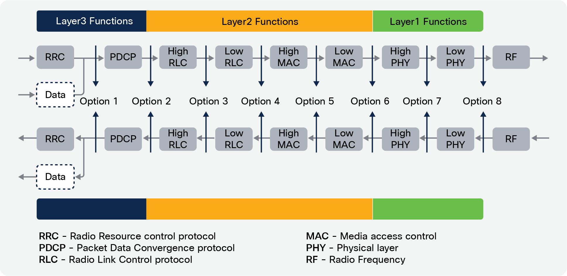
5G RAN functional split options (Source: 3GPP)
Following are two of the popular split RAN implementations.
● Split option 2: Layer 3 functions are implemented in the CU. Layer 2 and Layer 1 are implemented in the radio unit, also called the DRU. This enables the benefits of centralized Layer 3 and Self-Organizing Networks (SON). This architecture is suitable for mmWave (FR2) implementations and for Non- Standalone (NSA) deployments.
● Split option 7.2: This option can be seen as an extension to split option 2. In this option, Layer 3 functions are implemented in the CU. Layer 2 and upper Layer 1 functions are implemented in the DU. Lower Layer 1 and radio functionality are implemented in the RU. This enables you to leverage the benefits of centralized Layer 3 resource management and the benefits of centralized scheduling in Layer 2 and Layer 1 while distributing the radio-specific functionality into individual radio units.
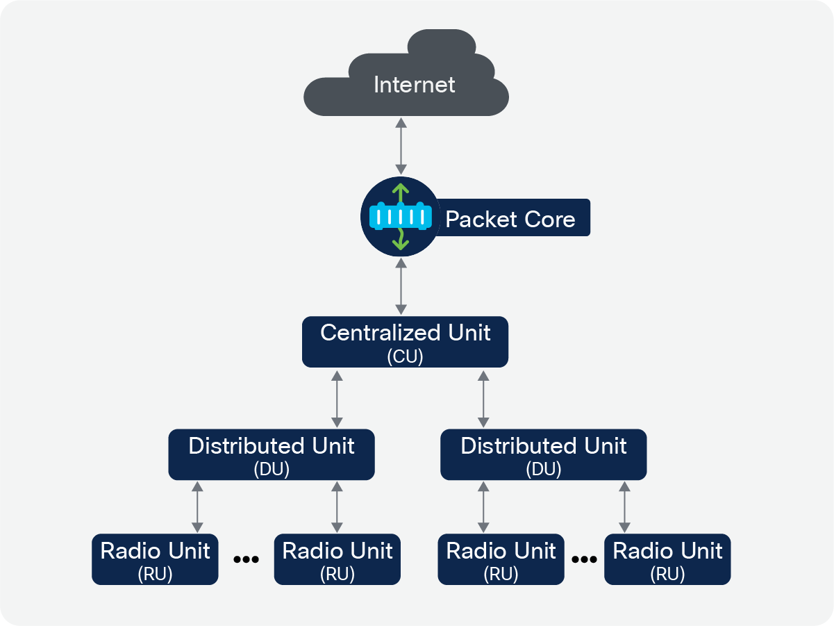
Split RAN (O-RAN/vRAN) architecture
Another implementation option is the integrated cell, which will find its way into pico and small cell implementations. RAN is aggregated as a one-box solution. This simplifies the deployment of integrated cells. This deployment architecture is akin to that based on Wi-Fi access points.
Integrated cells would typically be used as a coverage extension to provide cellular coverage for small regions where macro coverage is insufficient. In addition, dense small cell deployments can be used to address the capacity needs of larger areas where the device population is concentrated. Integrated small cell architecture is particularly suited for distributed branch connectivity and smart cities where the solution can be managed by a service provider or the city.
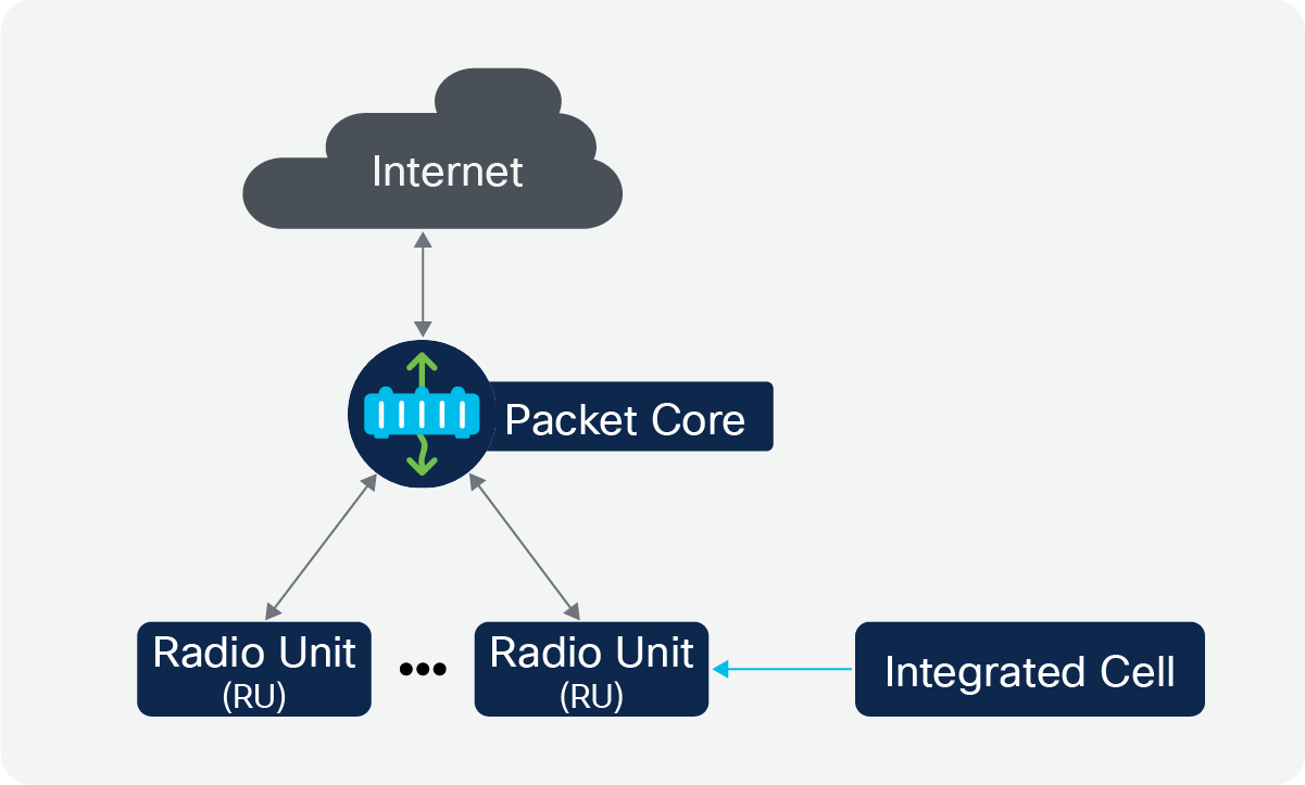
Integrated RAN architecture (small cells or pico cells)
In the 5G specification, 3GPP has attempted to address the needs of enterprises along with traditional service provider cellular use cases. Key use cases that are of interest to enterprises are:
● Ultra-reliable low-latency services
● Faster and more reliable mobility
● Massive machine-to-machine type communications
● Secure private communications
Governments worldwide are looking into reserving part of the spectrum for industrial enterprise use, also called private shared spectrum. Private spectrum is geography dependent. Each government might have a different policy in terms of how spectrum is assigned, auctioned, and handled. Private spectrum is typically lightly licensed and may involve a nominal fee. Unlike licensed spectrums used by service providers to enable public telephony and internet services, the use of private spectrum is typically limited to a facility or a building. The same part of the spectrum could be assigned to another user next door, which is why it is also called shared spectrum. Private spectrum makes 5G attractive for enterprises in addressing the above use cases that may not be reliably achieved with Wi-Fi due to its nondeterministic behavior and increased contention and channel access times.
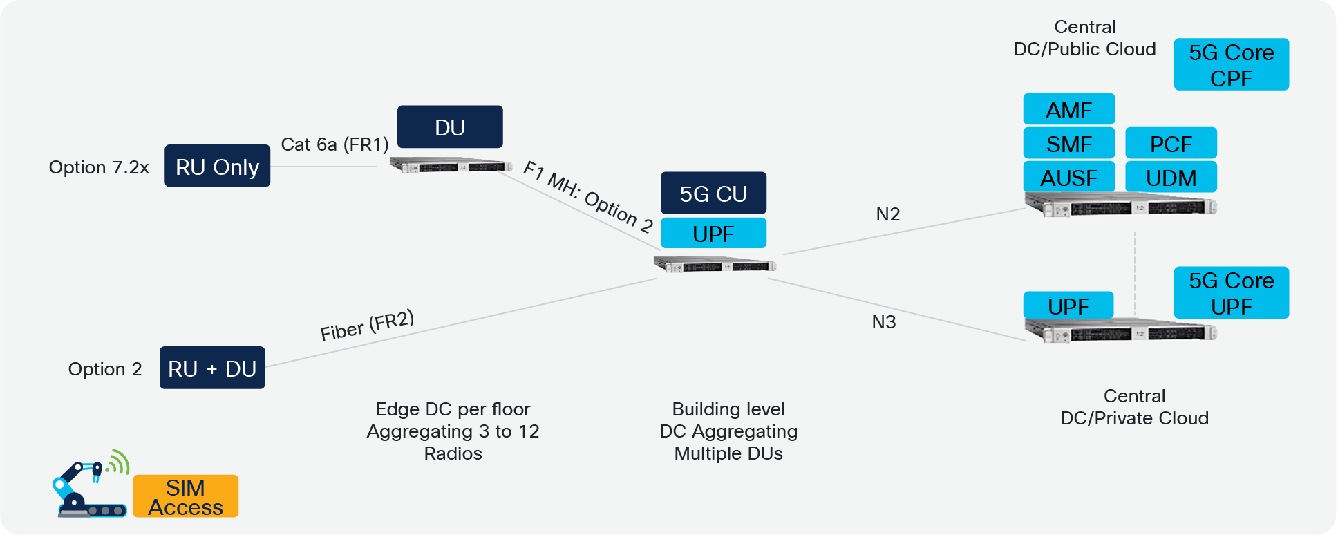
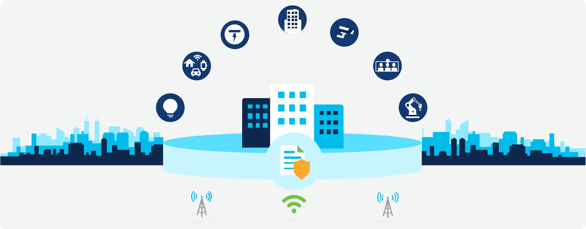
Typical 5G enterprise deployment
RAN architectures for private 5G enterprise use cases
The manufacturing, mining, and healthcare sectors fall into the category of early adopters. Industrial automation involving communication between Programmable Logic Controllers (PLCs), sensors, and AGVs requires ultra- reliable low-latency communications. Faster and more reliable handoff is an important requirement in the use of AGVs.

Manufacturing plant
Split RAN architecture option 7.2 may be better suited to meet the demands of mission-critical use cases. To improve reliability for networks or portions of networks serving mission-critical applications a variant of the split RAN architecture can be implemented to enable a group of radios that act as a single cell and share the same cell-specific parameters. In this architecture, wherever the UE may be within the coverage area of this group of cells, it stays attached to the same cell. UE can roam freely between these radios without incurring any handovers. This architecture would be preferred for the following reasons:
● Efficient spectrum allocation: Centralized Layer 2 and Layer 3 allows the spectrum to be allocated among RUs based on channel conditions and load conditions at each RU.
● Better interference management: Centralized Layer 2 scheduling allows co-channel interference to be managed efficiently by distributing resource blocks among users on individual RUs where the interference could be high.
● Improved signal strength: Centralized Layer 2 scheduling allows joint transmission of the same data stream from multiple RUs to the same user if the user has overlapped coverage from multiple RUs. With this technique the user would experience significant channel gains, resulting in improved signal strength and the ability to operate at higher modulation and code rates than were possible previously.
● Uniform coverage: Due to overlapping coverage and centralized Layer 2 scheduling, users would experience uniform coverage, whether at the cell center or cell edge. Regardless of user location, throughput would remain uniform.
● Elimination of handovers: The probability of connection loss during handovers is higher due to changing channel conditions. The handover process involves off-channel neighbor cell measurements and interactions between the serving cell and the target cell. These add to the latency and handover time. By employing an architecture that configures a group of radios to act as single cells, wherever the UE may be, it will be served by the same cell. It appears as if the network is following the user. Because of this, when UE moves from the coverage area of one RU to the coverage area of another, it will not experience any handovers. Configuring a group of radios to act as a single cell is just one of the many options for how the RAN architecture. This configuration options should only be employed for coverage area(s) of the network serving mission-critical applications
● Greater connection reliability: Uniform coverage and applying a configuration to a group of radios to act as a single cell to achieve zero handovers can minimize the block error rate, which helps improve the reliability of the connection and provides low user plane latency.
● Increased system capacity: Due to increased spectral efficiency of 4G and 5G technology. By applying smart RF design to and reduce interference and utilizing advanced RF performance features of 4G and 5G, more users can be handled and per-user throughput can be increased significantly at the system level.
● Centralized resource management allows better slice management, admission control, and SON capabilities.
● Upgradability: Support for newer RF bands, additional features, and 3GPP release upgrades can be easily supported with a software update on the DU. In the worst case only the RU hardware needs to be replaced, which is much cheaper than a complete replacement of the RAN system.
The benefits and flexibility offered by a split RAN architecture based on option 7.2 do bring various cost considerations, such as:
● Implementing baseband processing in a general-purpose compute platform may be expensive and cumbersome. In addition, compute power and memory requirements are significantly higher. Compute requirements can be reduced by offloading some of the digital processing such as Forward Error Correction (FEC) and enhanced Common Public Radio Interface (eCPRI) to an external accelerator card based on Field-Programmable Gate Arrays (FPGAs), eASICs or graphics processors.
● Deployment complexity will be higher due to multiple RAN elements involved. Fronthaul between the DU and RU needs to support higher capacity and tighter latency and jitter requirements. Every network switch between the DU and RU adds to the latency budget allowed on the fronthaul to meet application requirements. Unaccounted jitter and latency lead to a higher block error rate and sync loss between the DU and RU. In order to meet ultra-Reliable Low-Latency Communication (uRLLC) requirements, the DU and RUs are expected to be as close as possible. Up to three hops should be fine. Latency and jitter requirements on the link between the DU and CU are slightly relaxed; however, it should meet the reliability requirements.
● Management complexity increases due to multiple RAN elements involved. Automation and software orchestration techniques combined with integrating the enterprise network management system, can help minimize the complexity of managing the disaggregated nodes.
● Depending upon the size of the deployment, the cost of the equipment could be higher compared to an integrated small cell solution. The cost of the solution gets cheaper as the size of the deployment increases, due to the fact that the number of RUs per DU and the number of DUs per CU increase.
Healthcare, warehouses, and retail stores are all distributed enterprises. Coverage, high reliability, and deterministic mobility performance are the main factors in these deployments. Integrated small cells may be preferred for such deployments for the following reasons:
● Cost of solution: Typical coverage needs are much smaller compared to industrial/manufacturing deployments. Fewer small cells are sufficient to address the coverage needs, helping reduce the costs.
● Deployment simplicity: Reduction in the number of boxes simplifies deployment and reduces management complexity. Zero-touch deployment can be easily achieved.
● Ease of integration with existing network: Since integrated small cell architecture doesn’t involve fronthaul, the LAN is relieved from stringent network latency and jitter requirements. This means that expensive network replanning and upgrades are not absolutely needed. Small cells can be deployed on the enterprise’s existing network infrastructure.

Distributed enterprise
Across these types of deployments, vRAN-based architectures may be more suitable for mission-critical application needs. Integrated small cell-based architectures may have limited applicability due to following factors:
● The typical coverage area of a small cell operating on 3.5 to 3.8 GHz would be around 15,000 square feet with decent cell edge performance. Thus, many cells are required to cover a typical factory floor of 1 or 2 million square feet. This means robots and AGVs experience lots of handovers in their journey from one end of the building to the other. Handovers affect reliability and also increase user plane latency at the time of handover.
● The RF design, spectrum management and coordination of a large number of small cells is often a challenge, typically leading to more interference and lower efficiency in terms of bits/Hz.
5G and Wi-Fi may seem like competing technologies, but both are inherently designed to address different use cases. As mentioned earlier, 5G is designed for public telephony and internet services and use cases requiring deterministic behavior, while Wi-Fi is designed for typical data user application needs. The cost of the solution, spectrum availability, availability of clients, and complexity of the solution are other factors that influence the technology to be employed.
Together, Wi-Fi 6 and 5G can enable businesses to drive digital transformation. In general, Wi-Fi is easier to deploy and can be deployed as a standalone system. Wi-Fi is enabled in a vast number of client devices that are readily available at optimal cost. On the other hand, 5G is complicated and involves multiple elements to deploy. This may require reskilling of enterprise IT managers. In addition, global availability of spectrum for private 5G enterprise deployments is also limited. Initially, the cost of network equipment and client devices is also comparatively much higher. However, both 5G and Wi-Fi are needed to provide ubiquitous coverage as well as better mobility and have distinct application areas across various verticals including manufacturing, retail, hospitality, healthcare and industrial IOT. 5G and Wi-Fi can coexist in a single deployment and complement each other. For example, in a manufacturing facility, 5G can be used for mission-critical applications and Wi-Fi can be used for employee and guest internet access. In a healthcare facility, 5G can be used for the nurse call system and for transferring data from health monitoring systems, and Wi-Fi can be used for regular internet and office communications.
5G and Wi-Fi coexistence
Unlike its predecessors, 5G has been designed to address various use cases, both service provider and enterprise specific. 5G has the potential to grow as a mainstream access technology in both industrial and small and medium-sized business applications. Cost and complexity are the main constraints today, besides the availability of endpoints and spectrum to deploy at scale.
Learn about 5G Enterprise Technology.