Cisco Catalyst 9600 Series Architecture White Paper
Available Languages
Bias-Free Language
The documentation set for this product strives to use bias-free language. For the purposes of this documentation set, bias-free is defined as language that does not imply discrimination based on age, disability, gender, racial identity, ethnic identity, sexual orientation, socioeconomic status, and intersectionality. Exceptions may be present in the documentation due to language that is hardcoded in the user interfaces of the product software, language used based on RFP documentation, or language that is used by a referenced third-party product. Learn more about how Cisco is using Inclusive Language.
Enterprise campus networks are undergoing profound changes to support ever-increasing bandwidth demands on the access layer while moving toward supporting Wi-Fi 6/6E and the rapid growth of powerful endpoints. With access layer bandwidth moving from speeds of 1G to 2.5G, 5G, and 10G, higher bandwidths such as 25G, 40G, 50G, 100G, 200G1,and 400G will become the de facto speeds in distribution and core layers to maintain a similar over subscription ratio.
The Cisco Catalyst 9600 Series Switches are the next generation of the industry-leading business-critical modular enterprise campus core and distribution platform. The 9606R chassis is hardware-ready to support a switching capacity of up to 25.6 Tbps. The 9600 Series switches support granular port densities that fit diverse campus needs, including nonblocking 400G (QSFP-DD); 200G1 (QSFP56); 40G and 100G (QSFP28); 1G, 10G, 25G, and 50G (SFP56); and 10M, 100M, 1G, 2.5G, 5G, and 10G (RJ-45). It is architected to support all the latest Cisco optics innovations, such as dual-rate 200G1/400G, 40G/100G, and 10G/25G optics.
The platform delivers maximum high availability with field-replaceable dual supervisors, redundant power supplies, and fan tray. The platform is campus-optimized with an innovative dual-serviceable fan tray design and side-to-side airflow and is closet friendly with a depth of approximately 16 inches.
This white paper provides an architectural overview of the Cisco Catalyst 9600 Series chassis, including system design, power, cooling, and storage options.
1Hardware capable.
The Cisco Catalyst 9600 Series platform is a modular switch based on the Cisco Unified Access Data Plane (UADP) 3.0 ASIC (Supervisor 1) and Cisco Silicon One Q200 ASIC (Supervisor 2), which not only protects your investment but also allows a larger scale and higher throughput (Figure 1). The platform runs on the modern open Cisco IOS XE operating system, which supports model-driven programmability, has the capacity to host containers with support for up to 960 GB of solid-state (SSD) storage, and can run third-party applications and scripts natively within the switch (by virtue of the x86 CPU architecture, local storage, and a higher memory footprint).
The Cisco IOS XE operating system offers enhanced high availability features such as In-Service Software Upgrade (ISSU), Stateful Switchover (SSO), Software Maintenance Upgrades (SMU), Graceful Insertion and Removal (GIR), and Cisco StackWise Virtual (SVL) technology. Improved high availability is also added via Titanium/Platinum-efficient, redundant power supplies as well as variable-speed, highly efficient redundant fans.
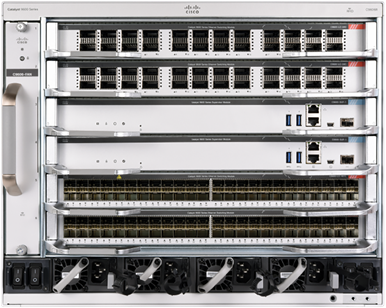
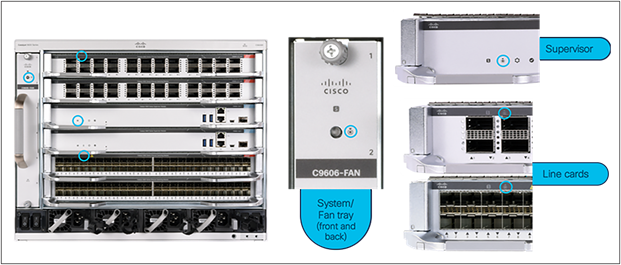
Cisco Catalyst 9600 Series
Chassis: The Cisco Catalyst 9606R is a 6-slot chassis. Two middle slots (slots 3 and 4) are dedicated for supervisors only, and they work in Stateful Synchronization (SSO) mode. The top and bottom two slots are for line cards. The chassis is designed to provide up to 6.4 Tbps full-duplex (3.2 Tbps for transmitting and 3.2 Tbps for receiving) from each of the supervisor slots to each of the line card slots. This means the system can provide 32 ports of 100G at line rate for each line card slot.
The backplane of the chassis is passive, which brings the following benefits:
● Lower power consumption, due to fewer components
● Higher Mean Time Between Failures (MTBF)
● Fan tray, power supplies, and line cards are field replaceable and can be replaced non-disruptively.
Supervisors: Cisco Catalyst 9600 Series Switches offer two supervisors: Supervisor Engine 1 and Supervisor Engine 2.
The Cisco Catalyst 9600 Series Supervisor Engine 1 (Sup-1) is powered with three UADP 3.0 Application-Specific Integrated Circuits (ASICs) (Figure 2). Each ASIC is capable of 3.2 Tbps (1.6 Tbps full duplex) switching capacity and up to 1 Bpps of forwarding performance. Together, the three UADP 3.0 ASICs with Sup-1 provide 9.6 Tbps full-duplex of switching capacity and up to 3 Bpps of forwarding performance. There are no uplinks on the Sup-1 as the ASIC connections are dedicated to the line cards.
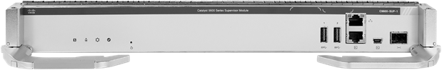
Cisco Catalyst 9600 Series Sup-1
The Cisco Catalyst 9600 Series Supervisor Engine 2 (Sup-2) is powered with one Cisco Silicon One Q200 ASIC (Figure 3). The Cisco Silicon One Q200 ASIC is capable of 25.6 Tbps (12.8 Tbps full duplex) switching capacity and up to 8 Bpps of forwarding performance. There are no uplinks on the Sup-2, as the ASIC connections are dedicated to the line cards.
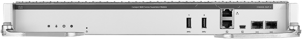
Cisco Catalyst 9600 Series Sup-2
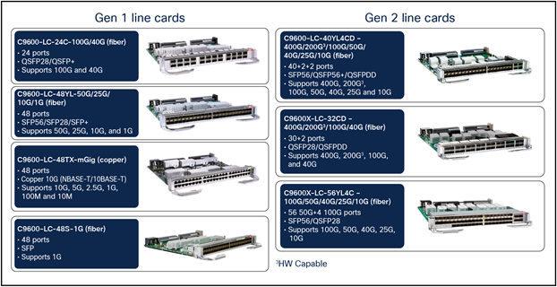
Line cards: Cisco Catalyst 9600 Series Switches offer the ability to mix and match a range of line cards to support different core and aggregation deployments (Figure 4).
Fiber line cards:
● C9600X-LC-56YL4C: 56-port 50G/25G/10G (SFP56/SFP28/SFP+) and 4-port 100G/40G (QSFP28/QSFP+) line card.
● C9600X-LC-32CD: 30-port 100G/40G (QSFP28/QSFP+) and 2-port 400G/200G3/100G/40G (QSFP-DD/QSFP56/QSFP28/QSFP+) line card.
● C9600-LC-40YL4CD: 40-port 50G/25G/10G/1G (SFP56/SFP28/SFP+/SFP), 2-port 200G3/100G/40G (QSFP56/QSFP28/QSFP+) and 2-port 400G/200G3/100G/40G (QSFP-DD/QSFP56/QSFP28/QSFP+) line card.
● C9600-LC-24C: 24-port 100G/40G (QSFP28/QSFP+) line card.
● C9600-LC-48YL: 48-port 50G/25G/10G/1G SFP56/SFP28/SFP+/SFP line card.
● C9600-LC-48S: 48-port 1G SFP line card (not supported with Sup-2).
Copper line card:
C9600-LC-48TX: 48-port 10G/5G/2.5G/1G/100M/10M RJ-45 line card.
Line cards
This section briefly describes the highlights of the Cisco Catalyst 9600 Series chassis.
Table 1 provides information about the capabilities of the chassis.
Table 1. Chassis specifications
| Cisco Catalyst 9606R |
|
| Supervisor slots |
2 (slots 3 and 4) |
| Line card slots |
4 (slots 1 and 2 and slots 5 and 6) |
| Port density (Native interface) |
8 x QSFP-DD (400G) 16 x QSFP56 (200G1) 128x QSFP28 (100G), QSFP+ (40G) 224x SFP56 (50G), SFP28 (25G), SFP+ (10G) 192x SFP (1G) 192x RJ-45 (10G/5G/2.5G/1G/100M/10M) |
| Dimensions (HxWxD) |
13.95 x 17.4 x 16.1 in. (35.43 x 44.20 x 40.89 mm) (8RU) |
| Bandwidth per LC slot |
6.4 Tbps (3.2 Tbps full duplex) |
| Bandwidth between supervisor slots |
400G |
| Power supplies |
4 (N+1 and Combined mode) |
| Cooling |
Side to side |
1Hardware capable.
The power supplies are “Titanium/Platinum efficient” (95/90% or higher efficiency).
An ACT2 Trust Anchor Module (TAM) chip for module authenticity is supported on all supervisors, line cards, and fan trays.
Reversible Fan tray with N+1 redundant fans and flexible options to service the fan from the front or back (Figure 5).
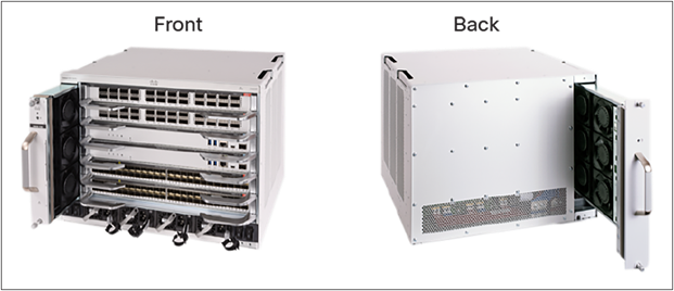
Flexible fan-tray servicing
The Cisco Catalyst 9600 Series uses a modular design for power. The 9606R has four slots for power supplies. Each power supply is very compact but highly efficient. The system provides support for both Combined and N+1 redundant mode.
By default, the system operates in Combined mode. In this mode, all power supplies are active and sharing the load. In N+1 redundant mode, one of the power supplies is configured as the standby power supply.
The Cisco power calculator (https://cpc.cloudapps.cisco.com/cpc/launch.jsp) can help you determine the power supplies required for a given configuration. The tool also provides heat dissipation information.
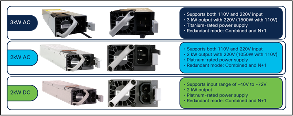
The maximum output power per Power Supply Unit (PSU) for the Cisco Catalyst 9600 Series is listed below, and each PSU has a power holdup time of approximately 20 milliseconds at 100 percent load. Each PSU comes with front-to-back variable-speed cooling fans and has a push-release lock for simple and secure online insertion and removal (Figure 6).
● 3000W AC PS with 240V input (1500W with 120V input; 16A input)
● 2000W AC PS with 240V input (1050W with 120V input; 10.5A input)
● 2000W DC PS with 48V input (50A input)
To enable a diverse range of deployments, the Cisco Catalyst 9600 Series also supports combinations of AC and DC units. When combining power supplies, both types of power supplies need to have the same power output level.
Power supply units
The Cisco Catalyst 9600 Series Switches support a hot-swappable and field-replaceable fan tray that can be replaced from the front or back, which offers significant flexibility with different cable management options. The chassis supports side-to-side airflow. The fan unit is responsible for cooling the entire chassis and for interfacing with environmental monitors to trigger alarms when conditions exceed thresholds. The fan modules contain thermal sensors to detect ambient temperature and adjust the fan speed. The chassis supports a hardware failure of up to one individual fan, and if a fan fails the remaining fans will automatically increase their rpm to compensate and maintain sufficient cooling. If the switch fails to meet the minimum number of required fans, it shuts down automatically to prevent the system from overheating.
Cisco Catalyst 9600 Series chassis are equipped with onboard thermal sensors to monitor the ambient temperature at various points and report thermal events to the system so that it can adjust the fan speeds.
The Cisco Catalyst 9600 Series fan tray supports side-to-side airflow for the modules and front-to-back airflow for the power supplies (Figure 7). The system can also be made into front-to-back airflow with an optional airflow kit sold separately.
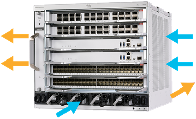
Chassis airflow
The Cisco Catalyst 9600 Series Switches are based on a centralized architecture (Figure 8). All forwarding, security, and queueing are done on the supervisor, while the line cards are considered transparent, containing only PHYs and control logic. Each line card slot has up to a 6.4-Tbps full-duplex connection to each of the supervisor slots.
The simplicity of this centralized design allows easy upgrade of features as well as additional bandwidth by just upgrading the supervisor while keeping the existing line cards. The combination of the centralized architecture and transparent line cards also provides uninterrupted supervisor switchover, which is the foundation for the In-Service Software Upgrade feature.
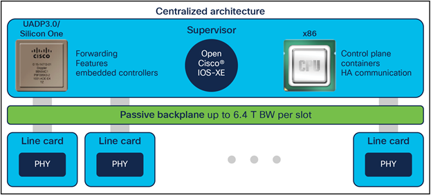
Cisco Catalyst 9600 Series architecture
The majority of the Cisco Catalyst 9600 Series components (chassis, supervisors, line cards, and fan tray) come with a built-in passive RFID for inventory management. All those components also have Blue Beacon, which can be turned on and off by the software (Figure 9). This helps locate the components when they need to be serviced. The power supply doesn’t have passive RFID or Blue Beacon.
Blue Beacon location on Cisco Catalyst 9600 Series components
Supervisor 1
The Cisco Catalyst 9600 Series Supervisor Engine 1 is powered by three UADP 3.0 ASICs and one x86 CPU processor (Figure 10). The three ASICs are interconnected with a 3.2-Tbps ASIC interconnect on each ASIC. Sup-1 provides 9.6 Tbps (4.8 Tbps full duplex). With the Cisco Catalyst 9606R chassis, each slot has 2.4 Tbps (1.2 Tbps full-duplex) with Sup-1.
Note: Due to high-performance line card requirements, the Sup-1 module doesn’t have any dedicated uplink ports (any port on any line card can be used as an uplink).
The supervisor architecture consists of the following main components:
● UADP ASIC
● ASIC interconnect
● X86 CPU complex
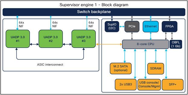
Supervisor Engine 1 block diagram
UADP ASIC
The supervisors are built on the UADP 3.0 ASIC, which is based on a multi-core System-On-Chip (SOC) architecture (Figure 11).
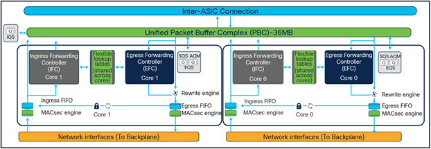
UADP 3.0 ASIC diagram
The UADP 3.0 ASIC is the latest generation in the UADP family. It is built with 16-nanometer technology that offers significantly larger tables and bandwidth compared to the other UADP ASICs. The UADP 3.0 continues to offer programmable pipelines and flexible allocation of hardware resources for different needs in different places in the network.
The following are the key UADP 3.0 capabilities.
● Packet bandwidth/switching throughput (full duplex): 1.6 Tbps (800 Gbps per core)
● Forwarding performance: up to 1 Bpps (500 Mpps per core)
● ASIC interconnects: 3.2 Tbps (1.6 Tbps full duplex)
● Forwarding Information Base (FIB) table: 416,000 (double-width entries optimized for IPv6)
● NetFlow: shared with FIB (IPv4 and IPv6 with double-width shared tables)
● Access Control List (ACL) TCAM: 54,000 entries
● Unified packet buffer: 36 MB
ASIC interconnect
The Cisco Catalyst 9600 Series Supervisor 1 is built with three UADP 3.0 ASICs (Figure 12). Communication within a core or between cores is locally switched within the ASIC, meaning that packets destined to local ports within the ASIC do not use the ASIC interconnect link. The purpose of the ASIC interconnect is to move data between multiple UADP ASICs.
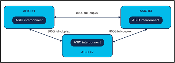
ASIC interconnect diagram
x86 CPU complex
As with other products in the Cisco Catalyst 9000 family, the 9600 Series uses the x86 CPU. The CPU complex has the following highlights:
● 2.0 GHz x86 8-core CPU
● 16-GB DDR4 RAM
● 16-GB internal enhanced USB flash
● M.2 SATA (SSD) internal storage (up to 960 GB)
● Console supports mini USB and RJ-45 connectivity
● Supports two USB 3.0 ports
● Management port supports RJ-45 (1G) and SFP/SFP+ (1G and 10G) (only one can be active)
● System reset switch for manually resetting the supervisor
Supervisor 2
The Cisco Catalyst 9600 Series Supervisor Engine 2 is powered by one Cisco Silicon One ASIC and one x86 CPU processor (Figure 13). Sup-2 provides 25.6 Tbps (12.8 Tbps full duplex). With the Cisco Catalyst 9606R chassis, each slot has 6.4 Tbps (3.2 Tbps full duplex) with Sup-2.
Note: Due to high-performance line card requirements, the Sup-2 module does not have any dedicated uplink ports (any port on any line card can be used as an uplink).
The supervisor architecture consists of the following main components:
● Silicon One Q200 ASIC
● X86 CPU complex
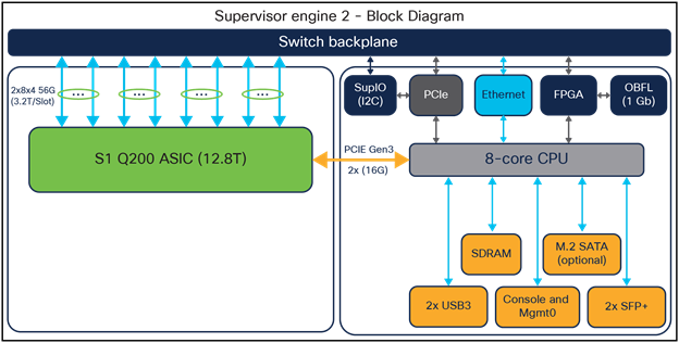
Supervisor Engine 2 block diagram
Cisco Silicon One Q200 ASIC
The Sup-2 is built on the Cisco Silicon One Q200 ASIC, which is based on a multi-slice System-On-Chip (SOC) architecture (Figure 14).
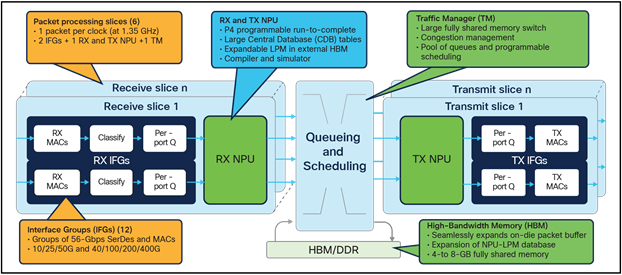
Cisco Silicon One ASIC diagram
Cisco Silicon One is a breakthrough technology that for the first time in history enables a single silicon architecture to span a massive portion of the networking market. It is built with 7-nanometer technology that offers significantly larger tables and bandwidth compared to the other Silicon One ASICs. The Cisco Silicon One Q200 continues to offer programmable pipelines and flexible allocation of hardware resources for different needs in different places in the network.
A recent design approach (similar to multicore and/or multi-ASIC), is to combine multiple Network Processing Units (NPUs) onto a single die package to multiply total capacity. Each ASIC NPU (called a “slice”) operates independently, and they are connected via an integrated crossbar “fabric.”
Multi-slice ASICs use an integrated Virtual output Queue (VoQ) buffer architecture to manage traffic between slices. Like the multicore design, this design approach addresses many of the limits of NPU clock speeds and cooling while also multiplying overall ASIC throughput.
The following are the key Q200 capabilities:
● Packet bandwidth/switching throughput: 25.6 Tbps (12.8 Tbps full duplex)
● Forwarding performance (6 slices): Up to 8 Bpps
● Forwarding Information Base (FIB) table: Up to 2M IPv4 routes, Up to 1M IPv6 routes
● Unified packet buffer: Up to 8-GB High-Bandwidth Memory (HBM)
x86 CPU complex
As with other products in the Cisco Catalyst 9000 family, the 9600 Series uses the x86 CPU. The CPU complex has the following highlights:
● 2.7-GHz x86 8-core CPU
● 32-GB DDR4 RAM
● 16-GB internal enhanced USB flash
● M.2 SATA (SSD) internal storage (up to 960 GB)
● Console supports mini USB and RJ-45 connectivity
● Supports two USB 3.0 ports
● Management port supports RJ-45 (1G) and 2x SFP+ (10G)
● System reset switch for manually resetting the supervisor
Cisco Catalyst 9600 Series Switches provide two types of external storage:
● USB 3.0 SSD on the front-panel of the supervisor
● M2 SATA (SSD) that can be plugged into the removable supervisor (up to 1 TB)
This external storage can be used for general-purpose storage for packet capture, operation system trace logs, and Graceful Insertion and Removal (GIR) snapshots. Most importantly, the M2 SATA (SSD) can be used for application hosting. An application hosted on a network device can serve a variety of purposes, ranging from automation, configuration management monitoring, and integration with existing tool chains.
Internal flash storage cannot be used to store third-party applications, as it is not supposed to be formatted as an EXT2 or EXT4 file system. But the M2 SATA (SSD) can support an EXT2 or EXT4 (default) file system and application hosting. It also has the ability to monitor the health of the SSD storage through Self-Monitoring, Analysis, and Reporting Technology (S.M.A.R.T.).
Supervisor and line card connections
Cisco Catalyst 9600 Series chassis line card slots have dedicated connections to both supervisor slots. Once the line cards are up and running, all traffic entering the line cards is sent to both the active and hot standby supervisors. The hot standby supervisor processes those packets just like the active supervisor does, and the resulting packets are sent to the egress line cards. The egress line cards themselves select the packets from the active supervisor and send them out of the front panel ports (Figure 15).
When there is a switchover between the supervisors, the PHYs in the line cards just need to switch the connection to the new active supervisor. As a result, the outage during this event is very minimal. This capability, together with the centralized architecture, enables the Cisco Catalyst 9600 Series to provide uninterrupted In-Service Software Upgrades.
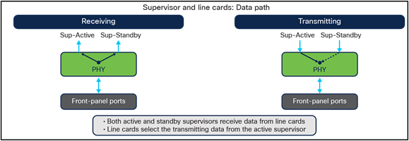
Supervisors and line card connections
The Ethernet PHY (physical layer) connects a link layer device (often a MAC) to a physical medium such as a transceiver. The PHY on the Cisco Catalyst 9600 Series Switches is a fully integrated Ethernet transceiver supporting steering and mapping of lanes back to the ASIC to enable multiple speeds depending on the optics inserted on the front panel ports or on whether copper ports are present.
C9600X-LC-56YL4C
Figure 16 shows the architecture of the C9600X-LC-56YL4C line card.
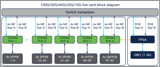
Diagram for the C9600X-LC-56YL4C line card
CDR5M 2.0 PHY is a fifth-generation 56G PAM4 x2 400G full-duplex clock and data recovery engine that provides speed transition between the ASIC and front panel. CDR5M PHY also provides MACsec/WAN-MACsec encryption at line rate.
Supervisor 2
● Up to 56 ports of 50G/25G/10G, and 4 ports of 100G/40G nonblocking
● Speed is auto-negotiated depending on the inserted optics
● LAN and WAN-MACsec are performed on the CDR5M 2.0 PHY
Note: Not supported with Supervisor 1
C9600X-LC-32CD
Figure 17 shows the architecture of the C9600X-LC-32CD line card.
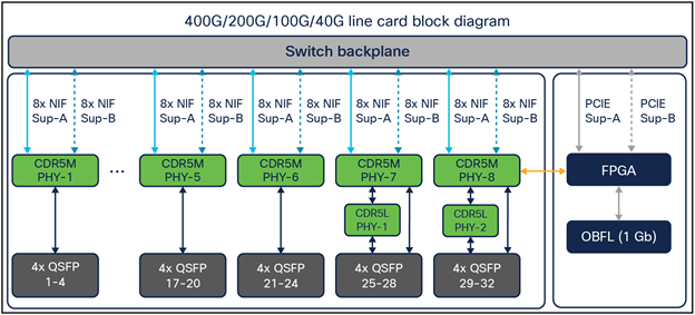
Diagram for the C9600X-LC-32CD line card
CDR5M PHY is a fifth-generation 56G PAM4 x2 400G full-duplex clock and data recovery engine that provides speed transition between the ASIC and front panel. CDR5M PHY also provides MACsec/WAN-MACsec encryption at line rate.
Supervisor 2
● Up to 30 ports of 100G/40G, and 2 ports of 400G/200G4/100G/40G nonblocking
● Speed is auto-negotiated depending on the inserted optics.
● LAN and WAN-MACsec are performed on the CDR5M PHY
Note: Not supported with Supervisor 1
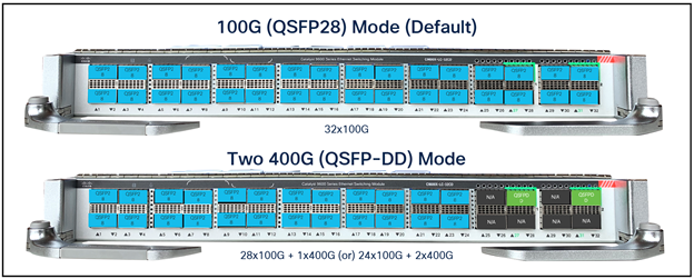
Available ports configuration mode with C9600X-LC-32CD line card
C9600-LC-40YL4CD
Figure 19 shows the architecture of the C9600-LC-40YL4CD line card.
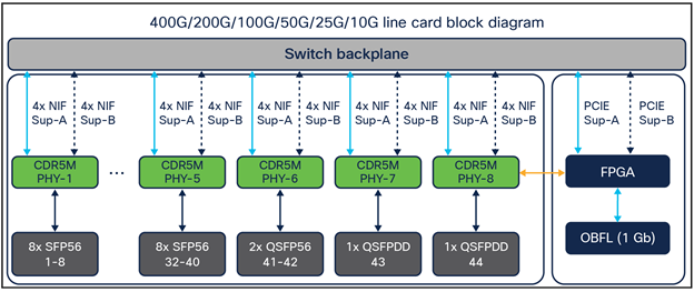
Diagram for the C9600-LC-40YL4CD line card
CDR5M PHY is a fifth-generation 56G PAM4 x2 400G full-duplex clock and data recovery engine that provides speed transition between the ASIC and front panel. CDR5M PHY also provides MACsec/WAN-MACsec encryption at line rate.
Supervisor 1
● Up to 40 ports of 25G/10G/1G, 2 ports of 100G/40G nonblocking
● Speed is auto-negotiated depending on the inserted optics
● LAN MACsec (no WAN-MACsec) is performed on Supervisor 1, and CDR5M is bypassed
Supervisor 2
● Up to 40 ports of 50G/25G/10G, 2 ports of 200G4/100G/40G, and 2 ports of 400G/200G1/40G nonblocking
● Speed is auto-negotiated depending on the inserted optics
● LAN and WAN-MACsec are performed on the CDR5M (PHY), when used with Supervisor 2
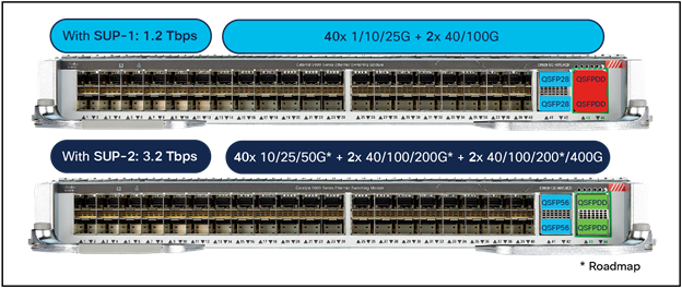
Available ports with Supervisor 1 and Supervisor 2
C9600-LC-24C
Figure 21 shows the architecture of the C9600-LC-24C line card.
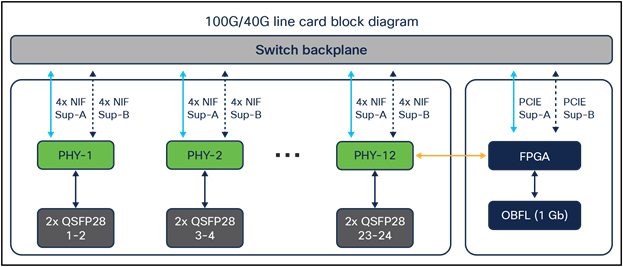
Diagram for the C9600-LC-24C line card
CDR4 PHY in this line card is a fourth-generation 56G PAM4 200-Gbps full-duplex clock data recovery engine that provides speed transition between the ASIC and front panel. This PHY does not include encryption.
Supervisor 1
● Up to 24 ports of 40G nonblocking (default mode).
● Up to 12 ports of 100G nonblocking (upper ports).
The upper ports can be enabled for 100G. When a 100G port is enabled, the subsequent port will be disabled. (Example: If port 1 is enabled as 100G, port 2 will be disabled).
● LAN MACsec (no WAN-MACsec) is performed on Supervisor 1.
Supervisor 2
● Up to 24 ports of 40G/100G nonblocking.
● CDR4 PHY does not support encryption, so MACsec is not supported when used with Supervisor 2.
Figures 22 and 23 show port numbering with Supervisor 1 and Supervisor 2, respectively.
The interface naming with Supervisor1 is “interface FortyGigabitEthernet1/0/1-24” or “HundredGigabitEthernet1/0/25-47”.
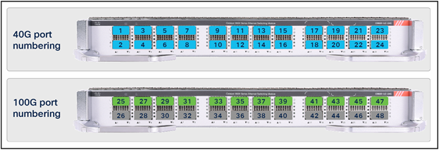
Port numbering with Supervisor 1
The interface naming with Supervisor2 is “interface “HundredGigabitEthernet1/0/1-24”
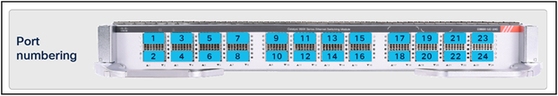
Port numbering with Supervisor 2
C9600-LC-48YL
Figure 24 shows the architecture of the C9600-LC-48YL line card.
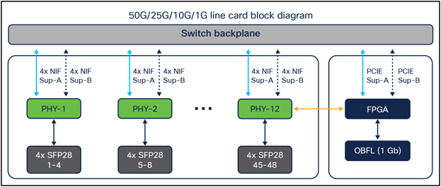
Diagram for C9600-LC-48YL line card
CDR4 PHY in this line card is a fourth-generation 56G PAM4 200-Gbps full-duplex clock data recovery engine that provides speed transition between the ASIC and front panel. This PHY does not include encryption.
Supervisor 1
● Up to 48 ports of 1G, 10G, or 25G nonblocking.
● Speed is auto-negotiated depending on the inserted optics.
● Supports 10G/25G dual-rate optics, optimized for campus distances (SFP-10G/25G-CSR-S supports 300 or 400 meters with OM3/4 cables at both10G and 25G).
● Interface naming: TwentyFiveGigabitEthernet1/0/1-48.
● LAN MACsec (no WAN-MACsec) is performed on Supervisor 1.
Supervisor 2
● Up to 48 ports of 10G, 25G, or 50G nonblocking.
● Interface naming: FiftyGigabitEthernet1/0/1-48.
● CDR4 PHY does not support encryption, so MACsec is not supported when used with Supervisor 2.
C9600-LC-48S
Figure 25 shows the architecture of the C9600-LC-48S line card.
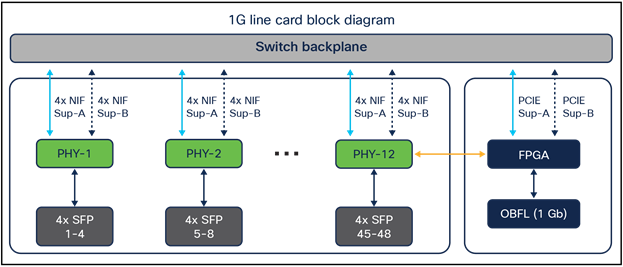
Diagram for C9600-LC-48S line card
CDR4 PHY in this line card is a fourth-generation 56G PAM4 200-Gbps full-duplex clock data recovery engine that provides speed transition between the ASIC and front-panel. This PHY does not include encryption.
● Up to 48 ports of 1G nonblocking (supported with Supervisor 1 only).
● LAN MACsec (no WAN-MACsec) is performed on Supervisor 1.
Note: Supervisor 2 does not support this line card
C9600-LC-48TX
Figure 26 shows the architecture of the C9600-LC-48TX line card.
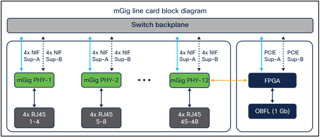
Diagram for C9600-LC-48TX line card
CDR4 PHY in this line card is a fourth-generation 56G PAM4 200-Gbps full-duplex clock data recovery engine that provides speed transition between the ASIC and front panel. This PHY does not include encryption.
Supervisor 1
● Up to 48 ports of 10M, 100M, 1G, 2.5G, 5G, or 10G nonblocking
● All ports are Multigigabit / 802.3bz
● No Power over Ethernet (PoE) on these ports
● LAN MACsec (no WAN-MACsec) is performed on Supervisor 1
Supervisor 2
● Up to 48 ports of 10G nonblocking
● No Power over Ethernet (PoE) on these ports
● CDR4 PHY does not support encryption, so MACsec is not supported when used with Supervisor 2
Supervisor and line card support matrix
The UADP ASIC on Supervisor 1 has an onboard MACsec engine, while the Cisco Silicon One Q200 ASIC doesn’t have an onboard crypto engine. Generation 2 line cards have a newer CDR5M PHY for MACsec. So, Generation 1 line cards (which use CDR4 PHY) with Supervisor 2 will not have MACsec capability.
Table 2. Line card support matrix
|
|
SUP-1 |
SUP-2 |
| C9600-LC-24C |
24x 40G or 12x 100G |
24x 40G and 100G (No MACsec) |
| C9600-LC-48YL |
48x 1/10G and 25G |
48x 10/25G and 50G (No MACsec, no 1G) |
| C9600-LC-48TX |
48x 1/2.5/5G and 10G (Multigigabit) |
48x 10G (No MACsec, no 1/2.5/5G) |
| C9600-LC-48S |
48x 1G SFP |
|
| C9600-LC-40YL4CD |
40x 1/10G and 25G + 2x 40G and 100G |
40x 10/25G and 50G + 2x 40/100G and 200G* + 2x 40/100/200G* and 400G MACsec and WAN MACsec (no 1G) |
| C9600X-LC-32CD |
|
30x 40G and 100G + 2x 40G/100G/200G* and 400G |
| C9600X-LC-56YL4C |
|
|
Supervisors – Mapping of front panel interfaces to ASICs
Supervisor 1
Figure 27 shows the mapping of the front panel ports to the ASICs. Spreading the ports within a port channel will maximize the utilization of hardware resources (buffer, forwarding, etc.) from each ASIC.
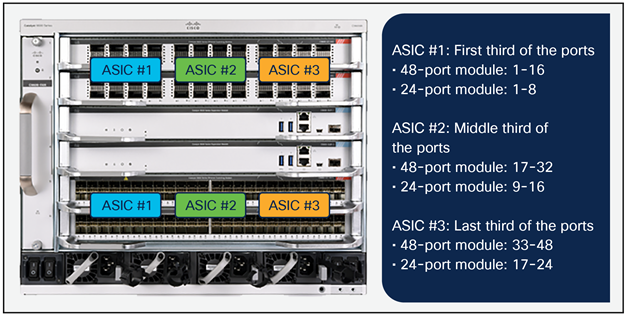
Diagram for front panel interface to UADP 3.0 ASICs mapping
Supervisor 2
A single Cisco Silicon One Q200 ASIC supports all of the slots and ports in the Catalyst 9606R chassis.
Supervisor 1 and Supervisor 2 comparison
The Catalyst 9600 family of switches is continuing the leadership in modular core and distribution switches by providing a full suite of campus core features along with higher performance and scale. With Supervisor 1, the Catalyst 9600 Series platform already provides a best-in-class core features set with hardware performance and scale for Catalyst 6500 and 6800 Series non-XL deployments. The new Supervisor 2 introduces higher port speeds (up to 8 ports of 400G) and superior hardware performance and scale (up to 2 million IPv4 routes, 256,000 MAC, and large buffer support) for migration of Catalyst 6500 and 6800 Series XL deployments.
Table 3. Supervisor 1 and Supervisor 2 hardware scales
|
|
|
Supervisor 2 (Silicon One™Q200) |
|
Supervisor 1 (UADP 3) |
||
|
|
Default |
Maximum (Custom) |
Default |
Maximum (custom) |
||
| MAC addresses |
128,000 |
256,000 |
80,000 |
128,000 |
||
| IP host routes |
128,000 |
256,000 |
80,000 |
128,000 |
||
| Multicast L2 groups |
16,000 |
64,000* |
16,000 |
48,000 |
||
| Multicast L3 routes |
32,000 |
64,000* |
32,000 |
48,000 |
||
| IP LPM routes |
2 millions |
2 millions |
212,000 |
256,000 |
||
| MPLS labels |
256,000** |
512,000** |
32,000 |
64,000 |
||
| SGT/OG labels |
32,000 |
64,000 |
32,000 |
64,000 |
||
| NAT* sessions |
NA* |
NA* |
3000 |
27,000 |
||
| Security ACL entries |
8000 |
10,000* |
12,000 |
27,000 |
||
| QoS ACL entries |
8000 |
10,000* |
8000 |
21,000 |
||
| PBR* ACL entries |
8000 |
10,000* |
3000 |
16,000 |
||
This section provides a high-level overview of how packet forwarding is performed on the Cisco Catalyst 9600 Series Switches.
Supervisor 1 – unicast forwarding within UADP 3.0 ASIC
Figure 28 shows the basic sequence of events when packets enter the Cisco Catalyst 9600 Series front panel ports for unicast packet forwarding within the ASIC.
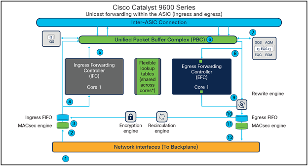
Unicast packet walk within a single UADP ASIC core
1. Packet arrives at the line card’s ingress port; PHY converts the signal and serializes the bits, and then sends the packet to the Network Interface (NIF) that goes to the backplane.
2. The packet travels through the backplane and enters the NIF of one of the ASICs.
3. The NIF passes the packet to the ingress MACsec engine. The MACsec engine will decrypt the packet if needed. The decryption is done at line rate. The packet now enters the Ingress First In First Out (FIFO).
4. The Ingress FIFO sends the packet to both the Ingress Forwarding Controller (IFC) and the Packet Buffer Complex (PBC) in parallel.
5. The IFC performs Layer 2, Layer 3, Access Control List (ACL), and Quality-of-Service (QoS) lookups and more, then returns the forwarding result (frame descriptor header) to the PBC.
6. The PBC uses the frame descriptor to determine the egress port. As the egress port is on the same ASIC, the result is sent to the Egress Queueing System (EQS) on the same ASIC.
7. The EQS receives the notification from the PBC and schedules the packet to be sent for egress processing.
8. The EQS signals the PBC to send the packet and descriptor out to both the Egress Forwarding Controller (EFC) and the Rewrite Engine (RWE).
9. The EFC completes egress functions and sends the final rewrite descriptor to the RWE.
10. The RWE performs packet rewrite with the final descriptor and sends the packet to the Egress FIFO.
11. The Egress FIFO sends the packet to the Egress MACsec.
12. The Egress MACsec performs a wire-rate encryption if required and then passes the frame on to the NIF. The packet then goes through the backplane and is sent out from one of the line card ports.
Supervisor 1 – unicast forwarding across UADP 3.0 ASICs
Figure 29 shows the basic sequence of events when unicast packets enter the Cisco Catalyst 9600 Series front panel ports and are sent across the ASIC interconnect link.
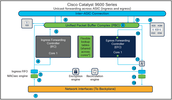
Unicast packet walk across UADP ASICs
1. Packet arrives at the line card’s ingress port; PHY converts the signal and serializes the bits and then sends the packet to the network interface (NIF) that goes to the backplane.
2. The packet travels through the backplane and enters the NIF of one of the ASICs.
3. The NIF passes the packet to the ingress MACsec engine. The MACsec engine will decrypt the packet if needed. The decryption is done at line rate. The packet now enters the Ingress FIFO.
4. The Ingress FIFO sends the packet to both the Ingress Forwarding Controller (IFC) and the Packet Buffer Complex (PBC) in parallel.
5. The IFC performs Layer 2, Layer 3, ACL, and QoS lookups and more to return the forwarding result (frame descriptor header) to the PBC.
6. The PBC uses the frame descriptor to determine the egress port. As the egress port is on a different ASIC, the Ingress Queueing System (IQS) schedules the packet to be sent to the destination ASIC using an inter-ASIC connection.
7. The PBC on the destination ASIC receives the packet from the source ASIC via the inter-ASIC connection.
8. The PBC sends the frame descriptor to the EQS.
9. The EQS receives the notification from the PBC and schedules the packet to be sent for egress processing.
10. The EQS signals the PBC to send the packet and descriptor out to both the Egress Forwarding Controller (EFC) and the Rewrite Engine (RWE).
11. The EFC completes egress functions and sends the final rewrite descriptor to the RWE.
12. The RWE performs packet rewrite with the final descriptor and sends the packet to the Egress FIFO.
13. The Egress FIFO sends the packet to the Egress MACsec.
14. The Egress MACsec performs a wire-rate encryption if required and then passes the frame on to the NIF. The packet then goes through the backplane and is sent out from one of the line card ports.
Supervisor 1 – multicast forwarding in UADP 3.0 ASIC
Figure 30 shows the basic sequence of events when packets enter the Cisco Catalyst 9600 Series front panel ports for multicast packet forwarding within the UADP ASIC.
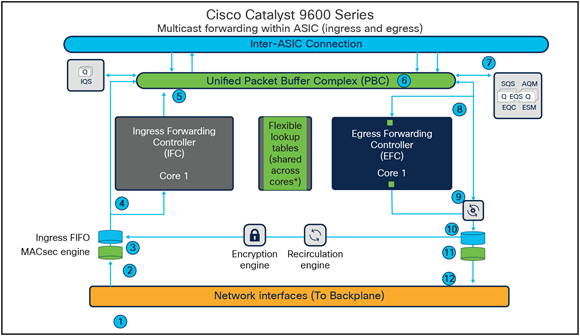
Multicast packet walk in UADP ASIC
1. Packet arrives at the line card’s ingress port; PHY converts the signal and serializes the bits and then sends the packet to the Network Interface (NIF) that goes to the backplane.
2. The packet travels through the backplane and enters the NIF of one of the ASICs.
3. The NIF passes the packet to the ingress MACsec engine. The MACsec engine will decrypt the packet if needed. The decryption is done at line rate. The packet now enters the Ingress FIFO.
4. The Ingress FIFO sends the packet to both the Ingress Forwarding Controller (IFC) and the Packet Buffer Complex (PBC) in parallel.
5. The IFC performs Layer 2, Layer 3, ACL, and QoS lookups and more, then returns the forwarding result (frame descriptor header) to the PBC. The frame descriptor in this case is a pointer to the replication table.
6. The PBC uses the frame descriptor to determine the egress port. (If there are receivers on other ASICs, the IQS will schedule the packet for the destination ASICs via the inter-ASIC connection.) For the local receivers, the result is sent to the Egress Queueing System (EQS).
7. The EQS receives the notification from the PBC. Based on the result, Active Queue Management (AQM) generates a list of egress ports and schedules the packet for each of those egress ports. The following steps are repeated for each of the egress ports in that list.
8. The EQS signals the PBC to send the packet and descriptor out to both the Egress Forwarding Controller (EFC) and the Rewrite Engine (RWE).
9. The EFC completes the egress functions and sends the final rewrite descriptor to the RWE.
10. The RWE performs packet rewrite with the final descriptor and sends the packet to the Egress FIFO.
11. The Egress FIFO sends the packet to the Egress MACsec.
12. The Egress MACsec performs a wire-rate encryption if required and then passes the frame on to the NIF. The packet then goes through the backplane and is sent out from one of the line card ports.
Supervisor 2 - unicast forwarding in Silicon One Q200 ASIC
Figure 31 shows the basic sequence of events when packets enter the Cisco Catalyst 9600 Series front panel ports for unicast packet forwarding within the Silicon One Q200 ASIC.
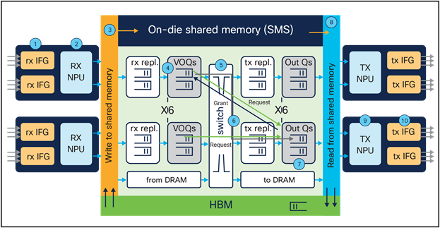
Unicast packet walk in Silicon One Q200 ASIC
1. Packet arrives at the line card’s ingress port; PHY converts the signal and serializes the bits, and then sends the packet to the Receive Interface Group (Rx IFG) through the backplane.
2. The packet’s Start-of-Packet (SOP) fragment (64B to 384B elements) is processed by the Rx NPU to determine the destination port. Non-SOP fragments bypass the Receive Network Processor Unit (Rx NPU) and are passed directly to the Shared Memory Packet Buffer (SMS).
3. The packet is stored in the SMS, and a corresponding Packet Descriptor (PD) is generated.
4. The PD is stored in the Virtual Output Queue (VOQ) according to destination port.
5. The VOQ requests credits from the destination Output Queue (OQ).
6. Once credit is granted from the OQ, the VOQ passes the PD to the slice crossbar.
7. Then the PD is switched by the crossbar and is stored in the destination OQ.
8. The PD is schedule from the OQ and presented to the SMS. Then the packet is read out to the Transmit Network Processor Unit (Tx NPU).
9. The packet is processed by the Tx NPU by editing the packet’s SOP elements.
10. The packet is then transmitted out of an interface within a Tx IFG.
Supervisor 2 – multicast forwarding in Silicon One Q200 ASIC
Figure 32 shows the basic sequence of events when packets enter the Cisco Catalyst 9600 Series front panel ports for multicast packet forwarding within the ASIC.
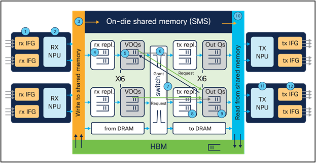
Multicast packet walk
1. Packet arrives at the line card’s ingress port; PHY converts the signal and serializes the bits, and then sends the packet to the Receive Interface Group (Rx IFG) through the backplane.
2. The packet’s Start-of-Packet (SOP) fragment (64B to 384B elements) is processed by the Rx NPU to determine the destination port. Non-SOP fragments bypass the Receive Network Processor Unit (Rx NPU) and are passed directly to the Shared Memory Packet Buffer (SMS).
3. The packet is stored in the SMS, and a corresponding Packet Descriptor (PD) is generated.
4. Receive replication (RXPDR) is processed for ingress replication. Each copy made by RXPDR results in an enqueue into the Virtual Output Queue (VOQ).
5. The replicated PDs are stored in the VOQ according to the destination ports.
6. The VOQ requests credits from the destination Output Queue (OQ).
7. Once credit is granted from the OQ, the VOQ passes the PD to the slice crossbar.
8. Then the PD is switched by the crossbar and sent to Transmit Replication (TXPDR) for egress multicast replication.
9. Once the packet is replicated, it is stored in the destination OQs.
10. The PD is scheduled from the OQ and presented to the SMS. Then the packet is read out to the Transmit Network Processor Unit (Tx NPU).
11. The packet is processed by the Tx NPU by editing the packet’s SOP elements.
12. The packet is then transmitted out of an interface within an Tx IFG.
Cisco Catalyst 9600 Series Switches are enterprise-class core and distribution switches in the Cisco Catalyst 9000 family, offering a comprehensive portfolio and architectural flexibility with interface speeds from 10M to 400G. This platform is based on Cisco’s next-generation programmable ASICs for increased bandwidth, scale, security, and telemetry. The platform also supports infrastructure investment protection with nondisruptive migration from 10G to 25G and beyond. The Cisco Catalyst 9600 Series is built on a modular system architecture designed to provide high performance to meet the evolving needs of highly scalable and growing enterprise networks.
The following websites offer more details on the Cisco Catalyst 9600 Series and its capabilities.
Cisco Catalyst 9600 Series Switches Data Sheet
Cisco Catalyst 9600 Supervisor Engine Data Sheet
Cisco Catalyst 9600 Series Line Cards Data Sheet
Cisco Catalyst 9600 - Migrating from Cisco Catalyst 6500/6800 to 9600 Series Switches
Cisco Catalyst 9600 Series Switches Hardware Installation Guide
Cisco Catalyst 9600 Series Supervisor Engine Installation Note
Cisco Catalyst 9600 Series Line Card Installation Note
25GE and 100GE – Enabling Higher Speeds in Enterprise with Investment Protection White Paper
The Key Role of 50G in Today's NG Networks White Paper
Benefits and Use Cases of QSFP-100G-ZR4-S White Paper
Cisco Catalyst 9000 Switching Platforms: QoS and Queuing White Paper
Cisco Catalyst 9000 Switching Platforms: StackWise Virtual White Paper
Cisco Catalyst 9000 - Switching for a New Era of Intent-based Networking
Application Hosting on the Cisco Catalyst 9000 Series Switches White paper