Cisco Catalyst 9000 Switching Platforms: QoS and Queuing White Paper
Available Languages
Bias-Free Language
The documentation set for this product strives to use bias-free language. For the purposes of this documentation set, bias-free is defined as language that does not imply discrimination based on age, disability, gender, racial identity, ethnic identity, sexual orientation, socioeconomic status, and intersectionality. Exceptions may be present in the documentation due to language that is hardcoded in the user interfaces of the product software, language used based on RFP documentation, or language that is used by a referenced third-party product. Learn more about how Cisco is using Inclusive Language.
This document describes the Quality-of-Service (QoS) and queuing architecture of the Cisco® Catalyst® 9000 family of switches. It explains the buffer, scheduling, policing, and remarking features. It provides details on how to manage the buffer sharing between multiple ports, on how AutoQoS can simplify deployments, and on how to specify custom QoS policies to meet application requirements.
Enterprise networks must provide end-to-end QoS solutions across the various platforms that span the network. Providing solutions for heterogeneous platforms often requires taking a different QoS configuration approach for each technology. As enterprise networks carry more complex, mission-critical applications and experience increased traffic from web multimedia applications, QoS serves to prioritize this traffic to ensure that each application gets the service it requires.
Networks must also handle increasingly complex business applications. QoS lets the network handle the difficult task of differentiating and using the inter-device links in the most efficient way for business applications.
QoS helps a network provide guaranteed and predictable services to selected network traffic by adding the following techniques:
● Scheduling to support guaranteed bandwidth
● Reducing loss characteristics for specified traffic
● Avoiding and managing network congestion
● Shaping network traffic
● Setting traffic priorities across the network
Using the above techniques to implement QoS in your network has the following advantages:
● Control over resources such as bandwidth, rate-limiting, and so on. For example, you can limit bandwidth consumed over a link by FTP transfers or give priority to an important database access.
● Coexistence of mission-critical applications:
◦ Bandwidth and minimum delays required by time-sensitive multimedia and voice applications are available.
◦ Other applications using the link, such as FTP, email, HTTP, or transactions, get their fair level of service without interfering with mission-critical traffic such as voice.
Moreover, by implementing QoS features in your network, you put in place the foundation for a future fully integrated network and use efficient techniques to manage congestion.
What is congestion?
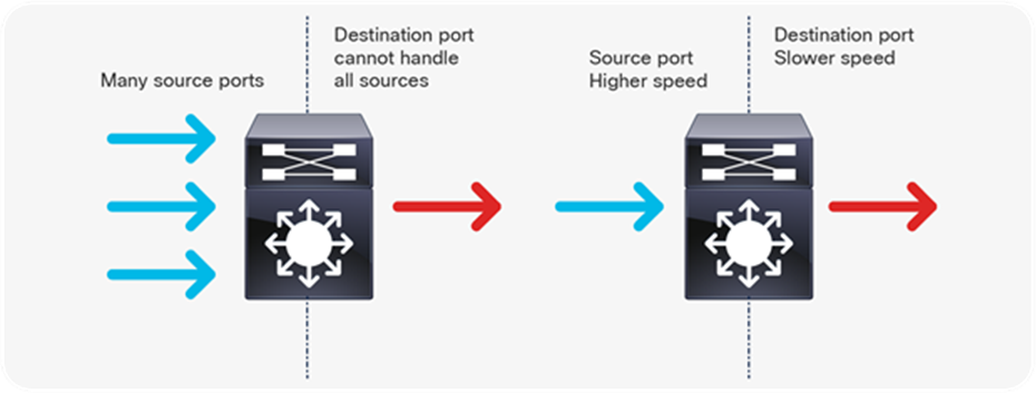
Congestion occurs when the destination port cannot transmit all packets out and some packets are dropped or delayed for longer than expected. Figure 1 illustrates the two types of congestion that require QoS and queuing.
Types of congestion
Types of congestion
The two types of congestion shown in Figure 1 are:
● Many to one: When multiple source ports are sending toward a single destination at the same time, the destination port can get congested with the amount of traffic it is receiving from multiple sources.
● Speed mismatch: When a port with higher speed transmits to a port with lower speed (for example 10 Gbps to 1 Gbps), packets will take time to drain out of the egress port, resulting in delay and/or packet drops.
Why do we care about congestion?
When congestion occurs, packets will be dropped if the congestion management features are not configured appropriately. When packets are dropped, depending on the upper layer protocol, retransmissions can occur, or networks might have to reconverge. In the case of retransmissions, the network performance can be impacted. In an already congested network, this can add to existing performance issues and potentially further degrade overall network performance. It can also result in temporary or full loss of connection in the case of Border Gateway Protocol (BGP), Open Shortest Path First (OSPF), Link Aggregation Control Protocol (LACP), etc., as the control plane protocols may not hear their keep-alive messages due to drops.
With converging networks, congestion management is even more critical. Latency and jitter-sensitive traffic such as voice and video can be severely impacted if delays occur. A simple addition of buffers is not always the solution. Understanding the traffic pattern of the applications and what they are affected by is a key step before looking into the solution.
To ensure QoS for a particular application, a certain set of tools might be required. The Cisco Catalyst 9000 family provides all the required tools to handle the applications commonly found in enterprise networks.
There are a few ways to manage congestion:
● Reduce the oversubscription ratio.
● Use a queuing scheduler to prioritize traffic.
● Use congestion management algorithms such as Weighted Random Early Discard (WRED) or Weighted Tail Drop (WTD) to drop some of the traffic earlier.
● Use buffers to reduce drops and increase the stored packets before transmitting.
● Police the traffic on ingress to reduce the traffic on egress.
The next section discusses how QoS features are integrated into different switch models.
Cisco Catalyst 9000 family integration of QoS into the ASIC
The Cisco Catalyst 9000 switching platform is the next generation in the Cisco family of enterprise LAN access, distribution, and core switches. Using the Cisco Unified Access® Data Plane (UADP) Application-Specific Integrated Circuit (ASIC), the platform delivers much higher performance and many new features and functionalities.
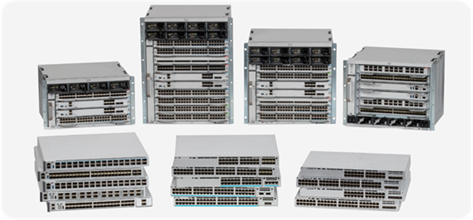
Cisco Catalyst 9000 family switches
The Cisco Catalyst 9000 switching platforms are built on a common and strong hardware and software foundation. The commonality and consistency bring simplicity and ease of operations for network engineers and administrators, reducing total operational cost and creating a better experience.
Common hardware
The hardware of the Cisco Catalyst 9000 family has a common design, both internally and externally. Internally, the hardware uses a common ASIC, the Cisco UADP, providing flexibility for packet handling. Another common component is the switch CPU. For the first time in the history of Cisco Catalyst switches, there is an x86-based CPU onboard (except for the Cisco Catalyst 9200 Series), allowing it to host additional applications beyond those normally possible on a network switch.
Common software
All Cisco Catalyst 9000 family switches run the exact same binary image of Cisco IOS® XE, except for the Cisco Catalyst 9200 Series, which has different CPU. Cisco IOS XE is an enhanced, open, and programmable OS. With a 30-year history behind it and thousands of features, Cisco IOS XE is arguably the most feature-rich OS in the networking industry. Having a single binary image shared across the Cisco Catalyst 9000 platforms enables end-to-end feature support and allows feature parity at any point in the network, such as Modular Quality of Service or MQC (discussed later). This commonality also helps when qualifying a software release, as only a single image needs to be tested for the entire campus network.
The similar hardware and software foundation of the Cisco Catalyst 9000 family enables the same end-to-end QoS features when newer models build on top of the base features. That brings consistency and simplicity for customers.
There are five members of the Cisco Catalyst 9000 family—the 9200 Series, the 9300 Series stackable switches, the 9400 Series modular chassis, the 9500 Series and 9500 Series High Performance fixed-configuration core switches, and the 9600 Series. The sections that follow discuss these platforms from a QoS architecture point of view.
Cisco Catalyst 9200 Series architecture
The Cisco Catalyst 9200 Series Switches have a simple architecture. All of the front panel ports, including the network module ports, are connected to one UADP Mini ASIC for the 24- or 48-port models or two UADP Mini ASICs for the Multigigabit models. The QoS buffer is shared among all ports, as the UADP Mini has a single ASIC core. Every port supports individual queuing capabilities.
The Cisco Catalyst 9200 Series are stackable switches using StackWise®-160/80. Each switch comes with two stack interfaces that can connect the switch to two other switches in a stack. The stack interface is part of the ASIC, which pushes the packets onto the stack ring. A dedicated amount of buffer is allocated for the stack interface and is not user configurable.
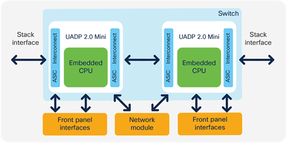
Cisco Catalyst 9200 Series architecture of dual ASIC switch
Cisco Catalyst 9300 Series architecture
The Cisco Catalyst 9300 Series Switches have a simple architecture. All of the front panel ports, including the network module ports, are connected to the UADP 2.0 ASIC. Depending on the model, the switch can have one or more ASICs serving all ports. For switches with more than one ASIC, generally the ports are equally divided among the ASICs, and therefore all ports will have an equal amount of resources available from each of the ASICs. The QoS buffer is provided per ASIC core and is shared only among the ports connected to that ASIC core. Every port supports individual queuing capabilities.
The Cisco Catalyst 9300 Series are stackable switches. Each switch comes with two stack interfaces that can connect the switch to two other switches in a stack. The stack interface is part of the ASIC, which pushes the packets onto the stack ring. A dedicated amount of buffer is allocated for the stack interface and is not user configurable.
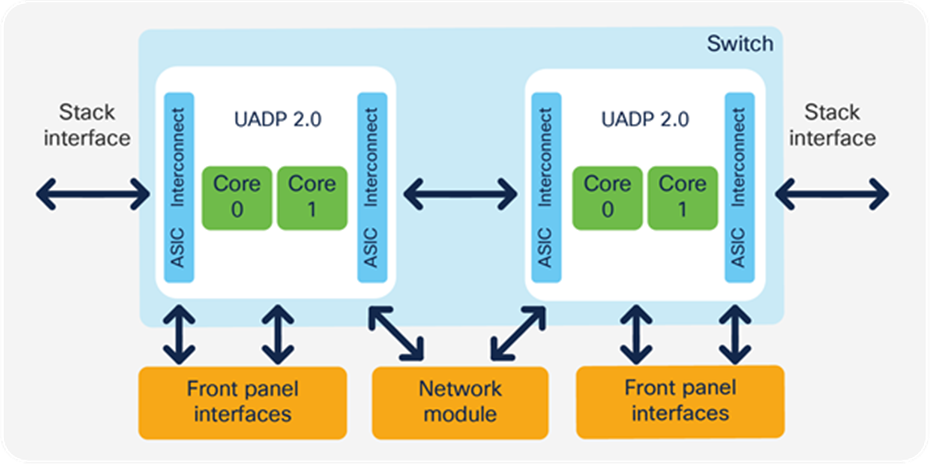
Cisco Catalyst 9300 Series architecture of dual ASIC switch
The Cisco Catalyst 9300-B switches are based on UADP 2.0 XL, which offers larger tables and deeper buffers for QoS in comparison to UADP 2.0 used in the rest of the Cisco Catalyst 9300 Series models.
Cisco Catalyst 9400 Series architecture
The Cisco Catalyst 9400 Series Switches are based on a centralized architecture, which means all packets are processed on the supervisor, while line cards are considered transparent, containing only stub ASICs and PHYs. Therefore, all QoS resources reside on the supervisor, including the per-port buffer and other QoS resources. The simplicity of this centralized design allows easy feature upgrades just by upgrading the supervisor while keeping the existing line cards.
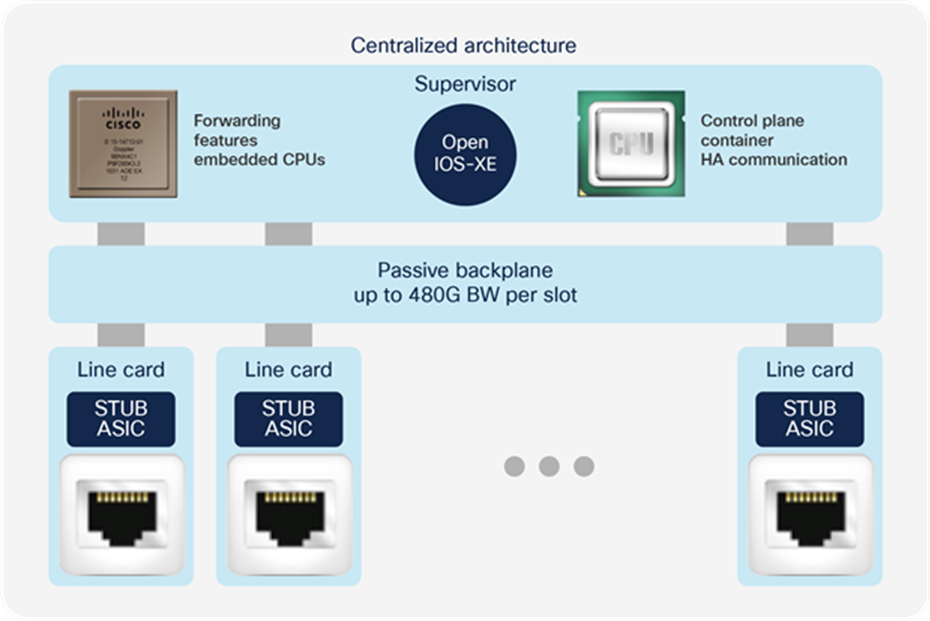
Cisco Catalyst 9400 Series architecture
The supervisor architecture is based on UADP 2.0 XL, which offers larger tables for QoS in comparison to UADP 2.0 used in the Cisco Catalyst 9300 Series.
Cisco Catalyst 9500 Series architecture
Each model in the Cisco Catalyst 9500 Series offers different port speeds and port density, but from a QoS architecture point of view, the 9500 Series is similar to the 9300 Series. Depending on the model, the 9500 Series switches are based on either UADP 2.0 XL or UADP 3.0. Table 1 summarizes the models and the ASICs used in each.
Table 1. UADP versions in the Cisco Catalyst 9500 Series
| Model |
UADP 2.0 XL |
UADP 3.0 |
| C9500-32C |
|
2 ASICs |
| C9500-32QC |
|
1 ASIC |
| C9500-48Y4C |
|
1 ASIC |
| C9500-24Y4C |
|
1 ASIC |
| C9500-16X |
1 ASIC |
|
| C9500-40X |
2 ASICs |
|
| C9500-12Q |
2 ASICs |
|
| C9500-24Q |
3 ASICs |
|
Figures 6 and 7 show the Cisco Catalyst 9500 Series Switches’ front panel-to-ASIC connections.
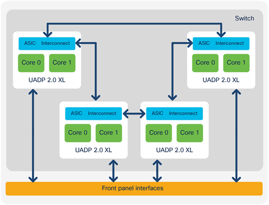
Cisco Catalyst 9500 Series architecture for models based on UADP 2.0 XL
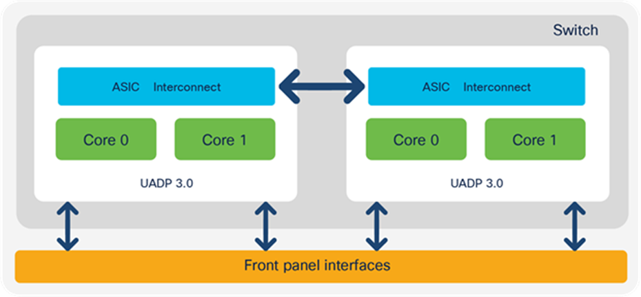
Cisco Catalyst 9500 Series High Performance architecture for models based on UADP 3.0
All switches that use the UADP 3.0 ASIC support a unified buffer between the two ASIC cores. That will increase the burst absorption, as it is a single shared buffer between all ports on the switch.

Difference between the UADP 2.0 (and 2.0 XL) and UADP 3.0 buffers
Cisco Catalyst 9600 Series architecture
Cisco Catalyst 9600 Series Switches are based on a centralized architecture, which means all packets are processed on the supervisor, while line cards are considered transparent, containing only PHYs. Therefore, all QoS resources reside on the supervisor, including the per-port buffer and other QoS resources. The simplicity of this centralized design allows easy feature upgrades just by upgrading the supervisor while keeping the existing line cards.

Cisco Catalyst 9600 Series architecture
The supervisor architecture is based on UADP 3.0, which offers larger tables for QoS in comparison to UADP 2.0 XL used in the Cisco Catalyst 9500 Series, and a unified buffer between the ASIC cores.
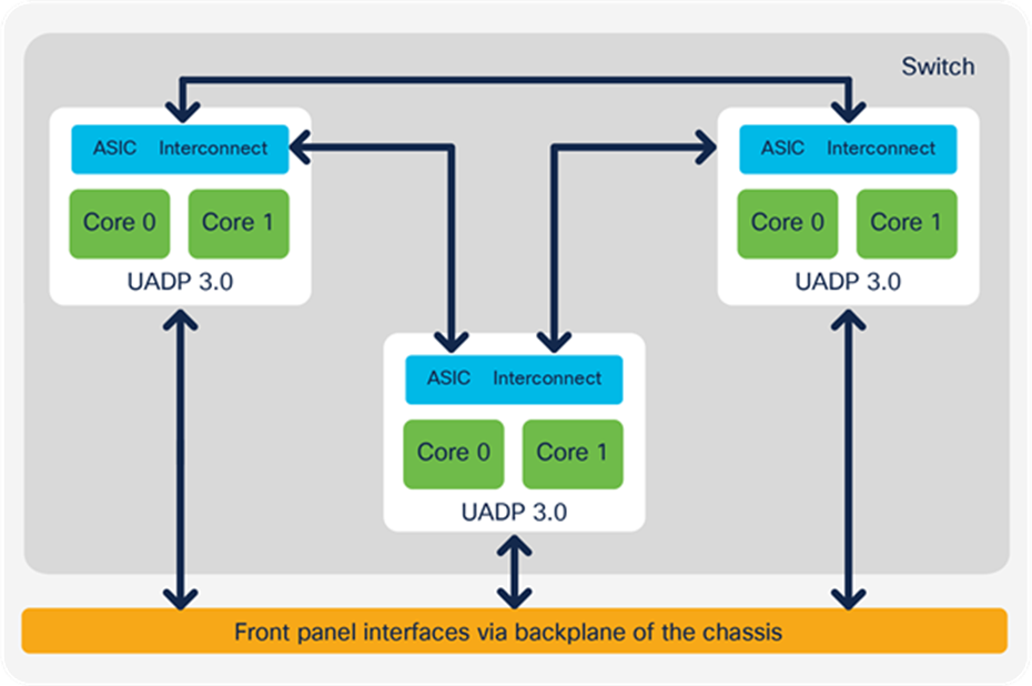
Cisco Catalyst 9600 Series ASIC interconnect
UADP packet walk
All of the UADP ASICs used in the Cisco Catalyst 9000 family use fields inside of the Ethernet frame or IPv4/IPv6 header to deliver QoS features at line rate. QoS features are performed hop by hop, where every hop can use the information from the packet header in its own way. But this is where the network administrator provides end-to-end management to unify the QoS services while considering all device capabilities on the packet paths.
The marking from the packet header is used to exchange service levels between hops. Every IPv4/IPv6 packet contains Layer 2 and 3 markers, which are designed to be used for QoS and queuing, but they are not the only option to classify the traffic in classes. The UADP ASICs can use source and destination IP addresses, TCP/UDP ports, and other packet header data to classify the packets as well.
Markers inside of the packet header can have following values:
● Layer 2 Class of Service (CoS): 3 bits (values are from 0 to 7)
● Multiprotocol Label Switching (MPLS) experimental bits (EXP) field: 3 bits (values are from 0 to 7)
● Layer 3 Differentiated Services Code Point (DSCP), IP precedence Type of Service (ToS) for IPv4; traffic class for IPv6: 6 bits (values are from 0 to 63)
If the packets originated from the switch, the CPU can set priorities and classify packets even if they do not have markers into the packet header. For example, LACP protocol data units (PDUs) are untagged, but the CPU can schedule them in priority queues via internal prioritization.
Additional detailed information about the packet formats is provided in Appendix C.
UADP 2.0 (and 2.0 XL) and 3.0 share the same ASIC packet walk for QoS and queuing. When a packet enters the system, it is associated with an internal descriptor. The descriptor is formed from multiple bytes, with some bits dedicated for QoS. These QoS bits are initially set as per the ingress markers into the packet header. The descriptor is used to hold temporary results from different lookup stages, and these results are used as input between different stages. The descriptor is associated with the packet until the packet leaves the switch. Once the final forwarding decision is done, the information from the descriptor is used to rewrite the packet.
When a packet enters the UADP ASIC, it goes to the MACsec block for decryption. Next, the ingress FIFO is used to create a copy of the packet, and while the packet is stored unchanged in the Packet Buffer Complex (PBC), the Ingress Forwarding Controller (IFC) will do multiple parallel lookups and will store the lookup results in the descriptor.
● If the packet needs to go over the stack, it will be sent over the Ingress Queue Scheduling (IQS) block and received from the stack by the Stack Queuing and Scheduling (SQS) block.
● If the packet will be sent over the same ASIC, it will skip the stack interface.
When the packet is received either from the stack or from the local PBC, it is ready for egress processing. It is sent to the Egress Queue System (EQS) for queuing. The EQS is built on two sub-blocks: the SQS, which received the packet from the stack, and Active Queue Management (AQM), which manages the port queues. Then a copy of the packet and the information from the packet descriptor that was set on ingress is used by the Egress Forwarding Controller (EFC) to apply the features configured on egress. Once the egress lookup completes, the final result is stored in the descriptor.
The packet is rewritten based on the final value in the descriptor. Next, the packet will be encrypted and sent out of the ASIC.
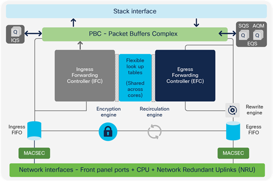
UADP ASIC core components
The packet walk from a QoS operations point of view can be split into four main parts:
1. Ingress classification, policing, and marking performed by the Ingress Forwarding Controller (IFC)
2. Queueing to the stack interface performed by the Ingress Queue Scheduling (IQS) and Stack Queuing and Scheduling (SQS) blocks
3. Egress queueing and scheduling performed by Active Queue Management (AQM)
4. Egress classification, policing, and marking performed by the Egress Forwarding Controller (EFC)
Figure 12 depicts these four parts. Each step is described in detail in later sections.
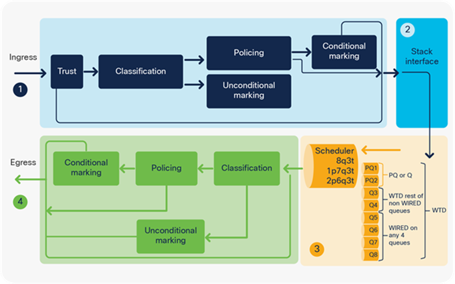
QoS tools per ASIC block
The ASIC provides hardware resources to process the packets; its scale numbers are provided in Appendix B.
Modular Quality of Service command-line (MQC) model
The MQC model is a standard way of configuring QoS across different product lines. Cisco Catalyst 9000 family switches use the same MQC model as a structured way to configure the different QoS tools such as policers, shapers, traffic remarking features, etc.
Every MQC policy is based on a class map, a policy map, and an interface target where the policy map will be attached. Figure 13 shows an MQC policy structure.
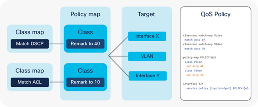
MQC policy structure
Figure 14 shows an example of a QoS policy.
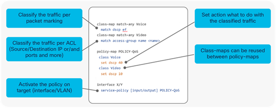
MQC sample policy
The QoS tools can be categorized as ingress and egress, as shown earlier in Figure 12. In that figure, parts 1 and 2 depict the ingress tools, and parts 3 and 4 depict the egress tools. The two QoS tool sets are discussed in the sections that follow. A combination of these tools can be used to achieve the desired quality of service.
On Cisco Catalyst 9000 family switches, for all incoming packets DSCP is trusted by default. The markings on the packets as they come in do not change unless a policy being applied for that packet changes the marking. This is unlike some of the older-generation platforms, such as the Cisco Catalyst 3750 Series, where enabling MPLS QoS would cause all incoming traffic to be untrusted and marked down to 0. On the Cisco Catalyst 9000 platform, all markings are retained unless a policy changes it.
Conditional trust
Cisco Catalyst 9000 family switches support conditional trust, which enables you to trust certain types of devices. The trust device command at the port level facilitates this capability. Once the trust device command is applied to a port, the port will trust only the trusted device. Packets from any other devices will not be trusted, and DSCP, IP precedence, or CoS will be remarked to 0.
For example, in the following configuration, only Cisco IP phones will be trusted. All other traffic will be remarked to 0.
interface <interface name>
description IP Phone
switchport access vlan 99
switchport mode access
trust device cisco-phone
Conditional trust can be enabled for only one device type on a port at a time. Although it is possible to have multiple devices on a single port, it is not possible to enable conditional trust for multiple device types at the same time.
For example, there might be an IP phone connected to the switch and a PC connected to the phone. IP phones are configured as trusted devices, while PCs are not. This can be a problem when provisioning trust in a mobile environment. Consider the following example:
● Port A is configured to trust the endpoint connected to it, which initially is an IP phone.
● Port B is configured not to trust the endpoint connected to it, which initially is a PC.
Because of a move, these endpoints get plugged into the opposite ports. This breaks the Voice over IP (VoIP) quality of calls made from the IP phone (now plugged into untrusted port B) and opens the network up for unintentional or deliberate abuse of provisioned QoS by the PC (now plugged into the trusted port A).
One solution is to have an intelligent exchange of information between the switch and the devices plugged into its ports. If the switch discovers a device that is trustworthy, it can extend trust to it dynamically; if not, then not. In the current Cisco implementation, the intelligent exchange of information is performed using Cisco Discovery Protocol.
Typically, IP phones have the ability to mark 802.1Q/p CoS values for both VoIP and call signaling (default values are 5 and 3, respectively). Furthermore, they also have the ability to mark VoIP as DSCP EF and call signaling as DSCP CS3.
Ingress classification is applied when the packet comes into the switch and policy is applied on the interface.
Cisco Catalyst 9000 family switches support classification using:
● Access Control Lists (ACLs) (source/destination IP, TCP/UDP ports, and more)
● DSCP
● IP precedence
● Traffic class
● CoS
● EXP (from 17.3.1)
● Network-Based Application Recognition (NBAR) protocols
● VLANs
The classification can use logical operators such as “AND” or “OR” between multiple classification parameters.
The following example highlights the differences between the “AND” and “OR” logical operators.
class-map match-any VOICE
match ?
access-group Access group
--- Or ---
dscp Match DSCP in IPv4 and IPv6 packets
Note: “match-any” specifies to match on the access-group OR DSCP value.
class-map match-all VOICE
match ?
access-group Access group
--- And ---
dscp Match DSCP in IPv4 and IPv6 packets
--- And ---
vlan VLANs to match
Note: “match-all” specifies to match on the access-group AND DSCP value AND VLAN.
The classification result will be used for:
● Policing
● Conditional or unconditional marking
For detailed information on how the UADP ASIC implements ingress classification in hardware, refer to Appendix A.
Ingress policer is another QoS tool that is used to reduce the ingress rate to a desired value. This section explains how policers achieve traffic reduction by immediately dropping the excess traffic.

How a policer works
The parameters used to configure the policers via the MQC model are discussed below.
● Policer rate and burst
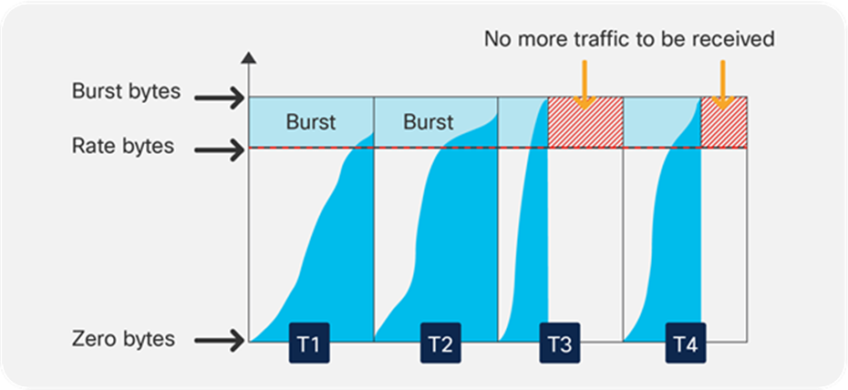
Two key parameters in the configuration of policing are rate and burst. The rate (also referred to as the committed information rate, or CIR) is defined as the maximum amount of data that can be forwarded in a given interval (normally referred to in Kbps, Mbps, or Gbps). The total amount of data that can be received in a given interval is called the burst.
A simple example of how these parameters interact could be a policy that uses a rate of 10 Mbps and a burst of 11 Mbps. This policy specifies that a maximum of 11 Mbps can be received in a given interval from which 10 Mbps (the rate) of data can be sent. The burst can be thought of as how much data can be received (imagine a bucket that can be filled), while the rate defines how much data can be forwarded (imagine how quickly the bucket is emptied).
An important point to stress is that the burst should never be less than the stated rate. If, for example, the burst was set at 8 Mbps, a rate of 10 Mbps would be impossible to achieve. If the bucket (burst receive size) can only ever hold 8 Mb, the maximum rate could be only 8 Mbps as well.
● Peak information rate and max burst
Peak Information Rate (PIR) and max burst are the next set of parameters that must be understood. If rate and burst are associated with the first bucket, the PIR and max burst are associated with a second bucket. The max burst defines the depth of the second bucket, while the PIR is the amount of data that can be forwarded from the second bucket. One way of thinking of PIR is as an extra small bucket that allows additional rate if resources are available.
● Hardware interval
The use of the term “given interval” for the rate definition above relates to a specific hardware-defined built-in interval. The policer rate accuracy is 0.0875%. The hardware interval is relevant to the rate at which tokens are replenished into the token bucket.
Policer token refill interval
As can be seen in Figure 16, data begins to arrive at the switch in a given interval and will be forwarded as long as the total count of data is within the defined rate (for that interval). Once the data count for a given interval exceeds the rate limit, the data will not be forwarded until the next hardware interval starts.
The hardware interval is usually referred as “Tc” when used for CIR or as “Tp” when used for PIR.
Policer configuration
Cisco Catalyst 9000 family switches support single-rate and two-rate policers. Figure 17 explains the sequence of action for policers.
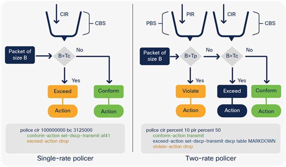
Types of policers in the UADP ASIC
The following is a sample MQC policy for policing:
class-map match-all dscp46
match dscp ef à Classification
policy-map InputPort
class dsp46
police rate percent 10 à Policer 10 % of interface line rate
interface <interface name>
service-policy input InputPort
Marking is another QoS tool that allows manipulation of various marking fields (CoS, DSCP/IP precedence, and EXP) in a packet. Cisco Catalyst 9000 family switches provide multiple ways to change the header. (Refer to Appendix C for details on the packet format.)
● Conditional marking: Changes the marker in a packet if a certain policing rate is exceeded.
● Unconditional marking: Marks all packets matching the policy.
Marking policy configuration
class-map match-all dscp20
match dscp 20 à Classification
class-map match-all dscp21
match dscp 21 à Classification
policy-map InputPort
class dscp20
set dscp af11 à Unconditional marking
class dscp21
police cir percent 10 pir percent 50
conform-action transmit
exceed-action set-dscp-transmit dscp table MARKDOWN
à Conditional marking, as the DSCP value is changed only if policing rate is exceeded
violate-action drop
class dscp22
police cir percent 10 pir percent 50
set dscp af11 à Unconditional marking can be combined with policing
interface <interface name>
service-policy input InputPort
● Mutation maps: These maps allow modification of the Layer 3 DSCP header based on Layer 2 CoS header information. Table 2 lists supported header mutations.
Table 2. Supported mutation map combinations
|
|
To: |
|
|
|
|
| From: |
Precedence |
DSCP/Traffic Class |
CoS |
QoS Group |
EXP |
| Precedence |
X |
X |
X |
X |
|
| DSCP/Traffic Class |
X |
X |
X |
X |
|
| CoS |
X |
X |
X |
X |
|
| QoS Group |
X |
X |
X |
|
X |
| EXP |
X |
X |
X |
X |
|
The following shows how to configure a mutation map:
table-map CoS2DSCP
map from 1 to 46
policy-map Mutation
class class-default
set dscp cos table CoS2DSCP
Where “set <to> <from>” sets the inter-marker mutation.
A policy supports the following capabilities when table-map is used:
● Only class-default can apply table-map.
● Mutation: A table map that maps from one DSCP value set to another DSCP value set, and this can be attached to an egress port.
● Rewrite: Packets coming in are rewritten depending upon the configured table map.
● Mapping: Table-map-based policies can be used instead of set policies.
To summarize, trust, classification, policing, and marking are tools that are applied on the ingress forwarding path, as defined in step 1 of Figure 12, “QoS tools per ASIC block.” These tools define the ingress QoS tool set. This section has provided MQC policy examples of how to use the tools.
The next section discusses step 2 of Figure 12, queuing to the stack interface.
Queueing to the stack interface to reach a different ASIC buffer
After the ingress forwarding result comes (either trusted or classified, then policed or remarked), the packet will be scheduled toward its destination ASIC. At this stage the information from the packet descriptor will be used to queue the packet. This information might be changed on the ingress forwarding path or might be kept as the original. The packet will not be rewritten and contains its incoming original QoS priority.
To transmit a packet from the PBC to the stack ring, the Ingress Queue Scheduler (IQS) block is used, as shown in Figure 11, “UADP ASIC core components”. The IQS provides the first level of queue structures to ensure that high-priority traffic is sent first. This is done to ensure that the priority of the packet is retained across the stack ring. The stack interfaces can be external, as in the Cisco Catalyst 9300 Series, or internal, as in the Cisco Catalyst 9400 Series, 9500 Series, and 9500 Series High Performance switches, but they all share the same functionality from a QoS and queuing perspective.
The stack interface provides only transport media and does not have any ability to change the packet priority. When a packet is received from the stack, it has exactly the same settings as when it entered from the origin ASIC core.
The stack interface provides eight separate queues for scheduling. Figure 18 shows the queue structure that uses the “TO” and “FROM” stack interface.
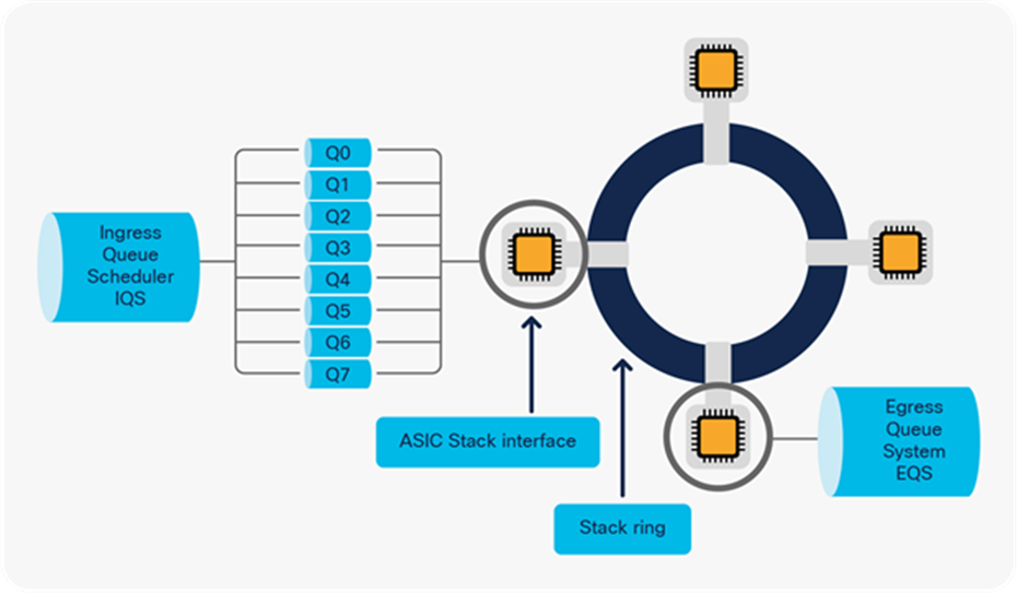
Inter-ASIC core connectivity
The packet is then sent to the egress port scheduler, shown in step 3 of Figure 12, and egress tools are used to process the packet further.
Egress queueing and scheduling
The egress port scheduler is another QoS tool that provides multiple port queues and buffer and queue thresholds. The scheduler is used to prioritize the sequence in which packets leave the interface. Every packet is placed in a queue with a different priority. The queue system works very similarly to a local grocery store that has a general queue as well as an “express” queue for people with only a few items. Figure 19 illustrates express/priority and regular queues.
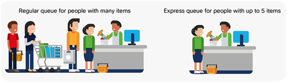
Different types of grocery store queues
To provide this queue structure, the UADP ASIC uses a block called Egress Queue System (EQS). The main components of EQS are as follows:
● Port queues
This type of queue allows packets to be grouped and processed in the same way. Having multiple queues allows the ASIC to select which queue to get the next packet from to send out. Queues are built inside of the ASIC per port. Using the grocery store analogy, every queue represents one cashier that processes the items purchased. Тhe express queue shows how people can purchase items faster and get out of the grocery store by reducing the processing time.
Figure 20 shows a visual representation of the port queue structures.

Front panel port queues
● The port is split into physical queues.
● Every queue has a buffer/memory that can be used to store packets.
● The number of queues used per port can vary from one to eight.
In the grocery store example, the people are aligned in queues according to the number of items they are purchasing. Similarly, the packets need to be assigned to queues in the ASIC. In the UADP ASIC, the information from the packet descriptor is used to map the packet to a queue. Once the packet is mapped to a queue, a scheduling algorithm will manage the order in which the queues are served. The priority/express queue can take priority, but for non-priority queues Weighted Round Robin (WRR) will be used to avoid congestion.
Why a strict priority queue? A strict priority queue can suppress any other transmission on the port and send the packets on that queue, when present. When a packet is placed into a strict priority queue, scheduling of packets from WRR queues will cease and the packet(s) in the strict priority queue will be transmitted. Only when the strict priority queue is empty will the scheduling process recommence sending packets from WRR queues.
Figure 21 illustrates in three steps how a strict priority queue takes precedence over WRR-served queues. The arrow for each sequence indicates which queue will be processed first.
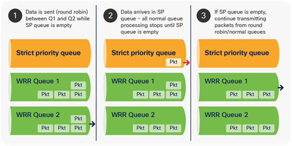
Strict priority queue processing over WRR queues
The UADP ASIC supports one strict priority level 1 Queue (PQ1) and one strict priority level 2 Queue (PQ2) per port. PQ1 and PQ2 operate outside of the bounds set by the WRR scheduling algorithm. The purpose of PQ1 is to process voice traffic with minimal latency. PQ2 is used to process video traffic, which can tolerate more latency.
Why WRR? A normal round robin algorithm will alternate between transmit queues, sending an equal number of packets from each queue before moving to the next queue. The weighted aspect of WRR allows the scheduling algorithm to inspect a weighting that has been assigned to each queue. This weighting defines how much bandwidth each queue has access to. The WRR scheduling algorithm will empty out more data from queues with a higher weighting (each interval) than other queues, thus providing a bias for designated queues.
Figure 22 shows that a different number of packets is sent from each queue. Because one queue has a higher bandwidth/weight, more packets are sent from it, as the queue is served more often.
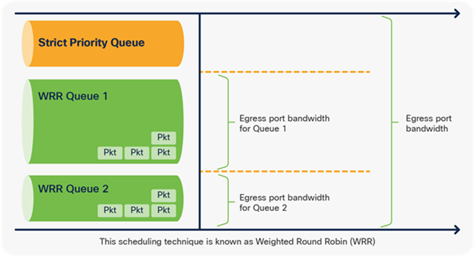
Bandwidth management in WRR queues
The default queue structure is unified across all Cisco Catalyst 9000 family switches for all ports, regardless of speed, and is based on a two-queue model. By default, priority and control traffic are separated into Q0 however Q0 is not set as priority queue.
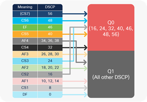
Default queue traffic mapping
The default queue settings can be changed by a custom MQC policy. The customer has the flexibility to use from a minimum of one queue up to a maximum of eight queues, where class-default is always defined, even if not specified explicitly in a policy map. The queue structures use a nomenclature to indicate how many normal and strict priority queues are supported, along with the number of thresholds available per queue. The keywords in the queue structure type include the following:
● Q: Indicates the number of normal queues or WRR queues for the UADP ASIC
● P: Indicates the number of strict priority (low-latency) queues
● T: Indicates the number of thresholds per normal queue; the strict priority queue does not implement thresholds
The following are examples of the queue nomenclature and sample mapping of the traffic to the queues.
1. 8q3t à 8 normal queues, 3 thresholds per queue
2. 1p7q3t à 1 priority queue, 7 normal queues, 3 thresholds per queue
3. 2p6q3t à 2 priority (level 1 and 2) queues, 6 normal queues, 3 thresholds per queue
The following is a sample MQC policy that uses class maps and a policy map to manage queue priority. The WRR bandwidth is tuned per queue, and the buffer ratio is adjusted manually. The thresholds will be discussed in a later section.
To assign traffic, use a DSCP, CoS, or QoS group. ACL classification cannot be used for queuing policy.
| class-map VOICE match dscp 46 class-map RT-VIDEO match dscp 32
* the rest of the class-maps are skipped
|
Classification to map traffic to queues |
| policy-map 2P6Q3T class VOICE priority level 1 queue-buffers ratio 5 class RT-VIDEO priority level 2 queue-buffers ratio 10 class MGT-CONTROL bandwidth remaining percent 10 queue-buffers ratio 10 class MULTIMEDIA-CONFERENCE bandwidth remaining percent 10 queue-buffers ratio 10 |
(continue...) bandwidth remaining percent 10 queue-buffers ratio 10 class TRANSACTIONAL-DATA bandwidth remaining percent 10 queue-buffers ratio 10 class BULK-SCAVENGER bandwidth remaining percent 5 queue-buffers ratio 10 class class-default bandwidth remaining percent 25 queue-buffers ratio 35 |
| interface <name> service-policy output 2P6Q3T |
|
Starting from 17.3(1) Egress Queuing is supported based on MPLS EXP as well.
To summarize, the UADP 2.0 ASIC and later supports a very flexible queuing model in which every port can have unique queuing settings and use a different number of priority queues or bandwidth settings.
● Queue buffers
Queue buffers are primarily used to:
◦ Hold traffic until a priority queue finishes transmitting
◦ Absorb a higher level of micro-bursts
◦ Store traffic between links with different speeds (higher to lower)
To return to the grocery store analogy, the queue buffers represent how many people can line up in a single queue before the store manager starts to move people to other lines.
To illustrate micro-bursts, Figure 24 shows the rate of the incoming traffic. There are moments when the number of packets to be processed spikes. The UADP ASIC provides physical memory to store the spikes instead of dropping these packets.
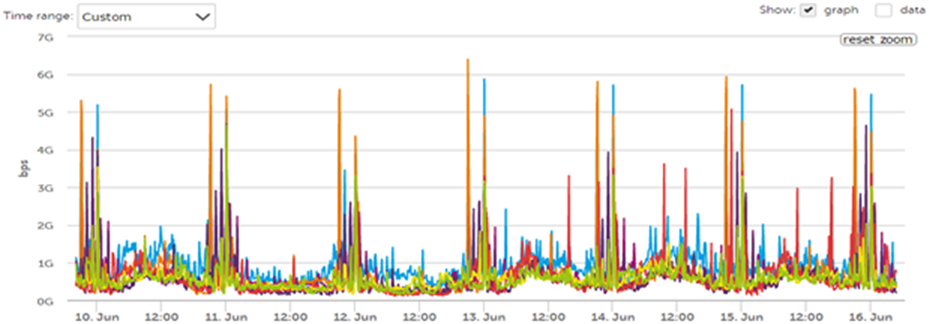
Traffic spikes/micro-bursts
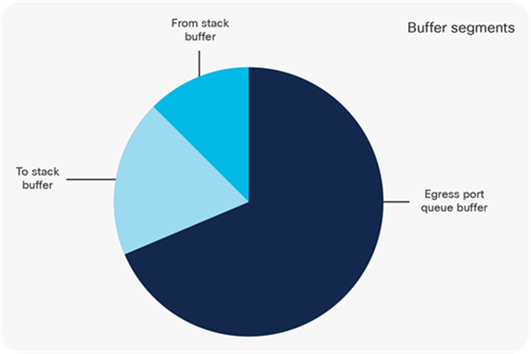
Buffer segments per UADP block
The entire physical buffer is split into multiple segments based on which part of the UADP ASIC will use the memory space:
● To-stack buffers are used for packets scheduled toward the stack interface. They are used by the IQS UADP ASIC block.
● From-stack buffers are used to receive the traffic from the stack interface. They are used by the SQS UADP ASIC block.
● The egress port queue buffer is the largest buffer and is used for port queue structures. This buffer can be shared between different queues or ports. It is used by the Active Queue Management (AQM) UADP ASIC block.
There are two approaches to assigning the buffers to these segments: static and dynamic. In the UADP ASIC, a static approach is used for to-stack and from-stack buffer blocks— IQS and SQS. But statically allocated buffers for the egress port queue buffer are inefficient and could lead to packet drop during bursts. In the UADP ASIC, every port queue has a minimum dedicated buffer by default and dynamically can add additional buffers from a shared pool to absorb higher bursts. The physical space in the shared memory pool is limited and will be mapped to a port queue when there is a traffic burst.
In the grocery store analogy, customers will resent being in a long line in a single queue rather than evenly split among all available queues. To be able to add more people to a queue that is already full, the store manager can put up temporary line borders to take physical space from less-used queues, which will provide more physical space to the queue experiencing congestion dynamically.
The Dynamic Threshold Scale (DTS) algorithm was introduced to improve UADP ASIC buffer performance with micro-bursts. DTS is part of the AQM block in the UADP ASIC.
DTS provides the following benefits:
● Dynamically allocates additional buffers per port per queue during bursts
● A shared buffer reduces the dropped traffic during micro-bursts
● Provides balance between the number of buffers that are shared and the number that are dynamically allocated
● Buffer management is flexible: dedicated plus shared
DTS performs the following functions:
● Creates a shared pool from the unused port buffers
● Enables a configurable dedicated threshold per port per queue
● Enables a configurable global maximum shared threshold
● Splits buffers per port between hard (dedicated) and soft (shared)
● Uses a dedicated buffer first, then shared ones to ensure fair consumption of the shared pool
The following are the steps to build a shared pool via DTS:
Step 1. DTS summarizes any free port buffers and creates a single shared pool that can be dynamically distributed during a micro-burst. The total SUM assumes that no traffic is there. Figure 26 shows the shared buffer space created.
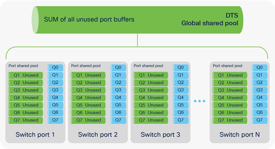
DTS global and port shared pools
Step 2. From the created shared pool, take buffers and allocate them to a port queue that experiences micro-bursts. Once the micro-burst finishes, the buffers are returned to the shared pool. Figure 27 shows how shared buffers are consumed.
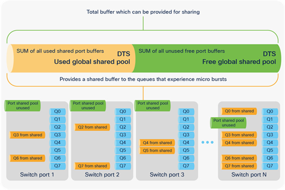
Global and port shared pools provide port queue adjustment
Next we will discuss the DTS parameters and how they are used to dynamically allocate buffers. Figure 28 shows the main parameters and their correlation.
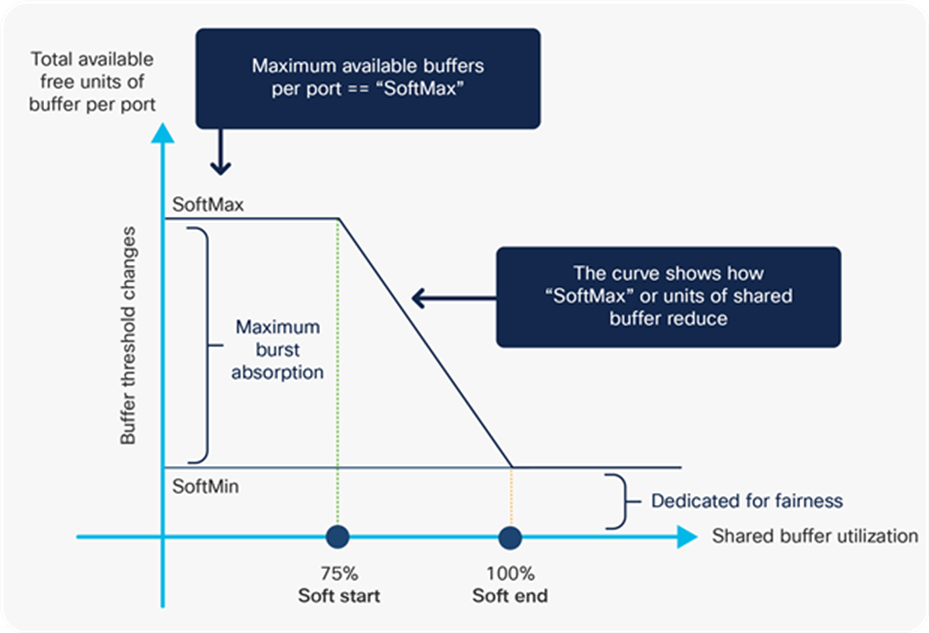
DTS parameters
Dedicated/hard buffers: This is the minimum reserved buffer for specific queues. The UADP ASIC uses hard buffers only for priority queue level 1. The hard buffers are not shown in Figure 28, but they will be shown in commands later and will be referred to as “HardMax.”
Shared/soft buffers: These buffers are assigned to a port queue dynamically but can be shared by other port queues. The parameters used to manage the soft buffers are:
● SoftMin: Minimum shared buffer given to the port. By default, a small piece from the shared buffer will be allocated to a non-priority queue to ensure that it can transmit traffic. It can be removed by configuration.
● SoftMax: Maximum buffer units the port queue can consume from the shared pool. This is a configurable parameter with a default of 100.
● Soft Start: The shared buffer is constantly monitored for utilization. If the total buffer utilization reached 75%, the dynamically allocated portions of buffer units per port queue will start to reduce. The higher the shared buffer utilization, the more aggressive the reduction of the buffer units.
● Soft End: Occurs when the shared buffer is fully utilized and cannot provide additional buffers to port queues to absorb micro-bursts (SoftMin and SoftMax are equal). The shared buffer will still provide a SoftMin buffer unit per port queue to ensure that these queues have minimum buffer to transmit, but nothing additional.
Per-port and global shared buffer pools: DTS manages two sets of shared pools:
● Global: Allows buffer sharing between ports. This pool uses the prefix “Global” in front of the parameter. For example: GlblSMin.
● Between port queues: Allows buffer sharing between port queues. This pool uses the prefix “Port” in front of the parameter. For example: PortSMin, PortStEnd.
When a port queue buffer needs adjusting, two independent adjustments are requested: from the global pool and from the port shared pool. The occupancy of the global pool and port pool are checked, and the port queue will take the adjustment from the shared pool that gives the larger adjustment and use it to absorb the micro-burst.
Next, the DTS parameters need to be associated with the port queues. Every port has two queues by default: Q0 (priority traffic) and Q1 (bulk traffic).
● Q0 has a dedicated/HardMax buffer allocated statically.
● Q0 can consume from the shared pool as well after HardMax is used.
● Q1 doesn’t have a dedicated/HardMax buffer allocated, but it has a dedicated piece from the shared pool equal to SoftMin.
● Softmax for Q0 is 4 times HardMax.
● When Q0 is set as priority level 1, SoftMax is set the same as the same as HardMax value
● Softmax for Q1 is 4 times GlobalSoftMin (GblSMin).
To read the port queue settings, use the command show platform hardware fed [switch] [active] qos queue config interface to display the DTS parameters in buffer units, which were discussed earlier, directly from the switch.
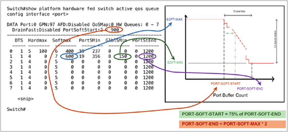
Mapping between DTS parameters and CLI to read the settings
To increase the number of units the port can request from the shared pool, increase the SoftMax threshold using the command qos queue-softmax-multiplier <100-1200>. The highest value is 1200 and will increase by a multiple of 12 the ability of a single port queue to absorb micro-bursts. This command will uplift the port queue thresholds so that the port queue can consume additional buffer units from the shared pool. The shared pool is a limited resource, as it is physical memory, and hence not all ports can consume from the shared pool all units they need to handle all micro-bursts. The buffer sharing itself assumes that the micro-bursts will not happen on all ports on the switch at the same time. If micro-bursts happen in random moments, the shared buffer will be able to dedicate additional buffer units to absorb them. By using DTS in this way, the UADP ASIC makes the use of the PBC buffer very efficient.
The total number of buffers per port cannot be increased, and the allocated buffer units depend on the port speed, but the number of buffer units per port queue can be modified from the default allocation.
The Cisco Catalyst C9300-24UB and C9300-48UB switches also provide an option to disable the stacking port, which will release the IQS and SQS buffers to the shared pool via the command qos stack-buffer starting from 16.12(1)
Cisco Catalyst switches based on UADP 3.0 can use the command qos share-buffer to enable the unified buffer functionality starting from 17.2(1)
Table 3 shows the total buffer units allocated per port speed for different Cisco Catalyst 9000 family switches.
Table 3. Buffer allocation per platform for various port speeds
| Platform |
Queue |
100 Mbps, 1, 2.5, 5 Gbps |
10 Gbps |
25 Gbps |
40 Gbps |
100 Gbps |
|||||
|
|
|
Hard |
Soft |
Hard |
Soft |
Hard |
Soft |
Hard |
Soft |
Hard |
Soft |
| Cisco Catalyst 9200 Series |
Q0 |
81 |
324 |
408 |
1632 |
– |
– |
– |
– |
– |
– |
| Cisco Catalyst 9300 Series |
Q0 |
100 |
400 |
600 |
2400 |
600 |
2400 |
2400 |
9600 |
– |
– |
| Cisco Catalyst 9400 Series |
Q0 |
176 |
700 |
176 |
700 |
176 |
700 |
176 |
700 |
– |
– |
| Cisco Catalyst 9500 Series |
Q0 |
200 |
800 |
1200 |
4800 |
1200 |
4800 |
4800 |
19,200 |
– |
– |
| Cisco Catalyst 9500 Series High Per and 9600 |
Q0 |
112 |
448 |
240 |
960 |
480 |
1920 |
720 |
2880 |
1920 |
7680 |
|
|
|
Soft |
Soft |
Soft |
Soft |
Soft |
Soft |
Soft |
Soft |
Soft |
Soft |
| Cisco Catalyst 9200 Series |
Q1 |
4721 (1 Gbps only) |
488 (1 Gbps only) |
1912 |
2448 |
– |
– |
– |
– |
– |
– |
| Cisco Catalyst 9300 Series |
Q1 |
150 |
600 |
300 |
1200 |
300 |
1200 |
3600 |
14,400 |
– |
– |
| Cisco Catalyst 9400 Series |
Q1 |
336 |
1344 |
264 |
1056 |
264 |
1056 |
337 |
10,800 |
– |
– |
| Cisco Catalyst 9500 Series |
Q1 |
300 |
1200 |
1800 |
7200 |
1800 |
7200 |
7200 |
28,800 |
– |
– |
| Cisco Catalyst 9500 Series High Per and 9600 |
Q1 |
336 |
672 |
360 |
1440 |
720 |
2880 |
1080 |
4320 |
2880 |
11,520 |
*Note: Table 3 refer most of the default numbers however there might be small adjustments per platform.
The following configuration shows how to redistribute 100% of the buffer units given on the port per queue. The MQC policy (reduce CLIs) can be applied only on the egress direction on the port.
policy-map 2P6Q3T
class PRIORITY-QUEUE
queue-buffers ratio <number>
class VIDEO-PRIORITY-QUEUE
queue-buffers ratio <number>
class DATA-QUEUE
queue-buffers ratio <number>
class class-default
queue-buffers ratio <number>
When the buffer units are modified manually, the user needs to ensure that every queue has a certain amount of buffer allocated. If no buffer units are allocated, the traffic on the queue will be dropped.
Example 1 shows a case that should never be configured, as it will cause a network outage.
policy-map 2P6Q3T
class PRIORITY-QUEUE
class VIDEO-PRIORITY-QUEUE
class DATA-QUEUE
queue-buffers ratio 50
class class-default
queue-buffers ratio 50
Example 1 has the following problems:
● Queue buffers add up to 100% of total port buffers from two queues only
● If each queue does not have a queue buffer specified, they get:
(100% - the specified queues with buffer) and then split it equally among queues that do not have a queue buffer set
As a result of the example 1 policy, queues “DATA-QUEUE” and “class-default” will consume the entire buffer, and the rest of the queues will drop any traffic scheduled to go out of them.
Example 2 shows how to do a proper buffer unit redistribution manually.
policy-map 2P6Q3T
class PRIORITY-QUEUE
queue-buffers ratio 10
class VIDEO-PRIORITY-QUEUE
queue-buffers ratio 10
class DATA-QUEUE
queue-buffers ratio 35
class class-default
queue-buffers ratio 45
As a result of the example 2 policy, every queue will have a buffer to enable it to transmit traffic.
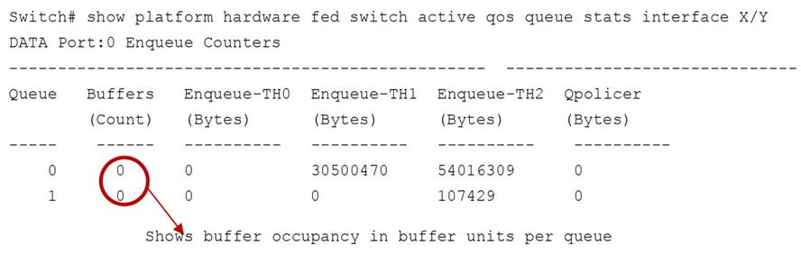
Another important command shows in real time how the buffer utilization varies per port queue. This command reads the values from the ASIC:
● Port queue thresholds
◦ Weighted Tail Drop (WTD)
Port queue thresholds are used to drop traffic earlier than the queue end (tail drop). If the port queue has the ability to drop specific traffic before the queue end, the port queue will keep buffer space for certain types of packets over the rest of the traffic managed by the port queue, based on the user configuration. Figure 30 shows the queue thresholds, where the user has the flexibility to assign a different DSCP, CoS, IP precedence, or traffic class.
Starting from 17.3(1) WTD capabilities are supported based on MPLS EXP as well.
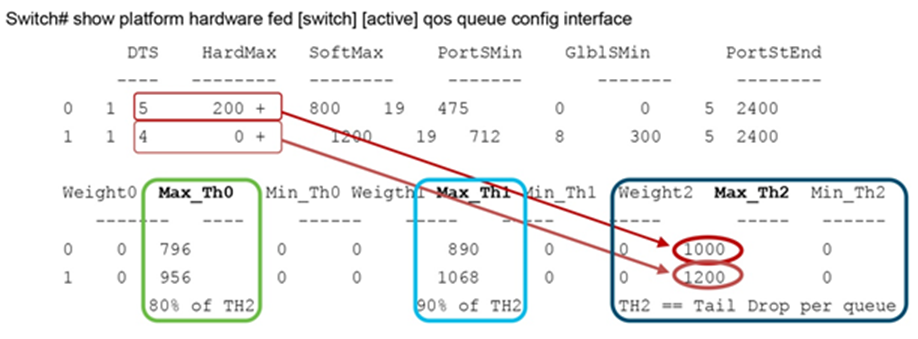
If the queue utilization goes above TH0, all new traffic configured to match this threshold will be dropped until queue utilization is reduced below TH0. The same applies for TH1 but with a different higher value than TH0 for a different group of traffic. TH2 might be reduced to less than 100%, but it will automatically shrink the queue tail end, as any traffic with QoS priorities not explicitly defined will match to TH2.

Single-port queue WTD thresholds
UADP ASICs offer up to three thresholds per port queue. The three thresholds on one queue need to use the same type of packet headers. For example, all three thresholds can use CoS within one queue, but other queues can use other packet headers such as DSCP. By default, TH0 is set to 80%, TH1 is set to 90%, and TH2 is set to 100% or the same as tail drop. All traffic is assigned to TH2 initially, but via MQC policy the threshold values can be changed. Another name for the threshold is Weighted Tail Drop (WTD), where every threshold is equal to a weight.
The following is a sample MQC policy to change WTD.
policy-map 2P6Q3T
class DATA-QUEUE
queue-limit dscp values af13 cs1 percent 80
queue-limit dscp values af12 percent 90
queue-limit dscp values af11 percent 100
To see the thresholds configured in the ASIC, use the following command:
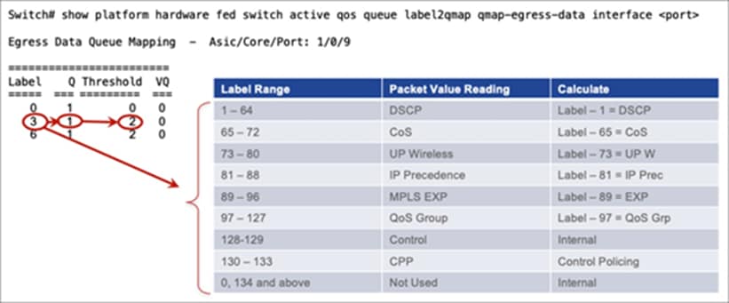
To see what traffic type is assigned to a queue and threshold, you need to map the traffic types to a label and use a second command to see which queue the label is applied to. Labels are used in this case to improve sharing capabilities.
Step 1. Find the label the DSCP, CoS, or EXP is assigned to, using the following command:
Switch# show platform software fed [switch] [active] qos tablemap dir ingress interface <name>
Label legend: DSCP:1 COS:65 UP:73 PREC:81 EXP:89 GROUP:97 CTRL:128 CPU:130
DSCP-to-Label --
0-Label: 1 1-Label: 2 2-Label: 3 3-Label: 4
4-Label: 5 5-Label: 6 6-Label: 7 7-Label: 8
….
COS-to-Label --
0-Label:65 1-Label:66 2-Label:67 3-Label:68
4-Label:69 5-Label:70 6-Label:71 7-Label:72
UP-to-Label --
0-Label:73 1-Label:74 2-Label:75 3-Label:76
4-Label:77 5-Label:78 6-Label:79 7-Label:80
PREC-to-Label --
0-Label:81 1-Label:82 2-Label:83 3-Label:84
4-Label:85 5-Label:86 6-Label:87 7-Label:88
EXP-to-Label --
0-Label:89 1-Label:90 2-Label:91 3-Label:92
4-Label:93 5-Label:94 6-Label:95 7-Label:96
GROUP-to-Label --
0-Label: 0 1-Label: 0 2-Label: 0 3-Label: 0
4-Label: 0 5-Label: 0 6-Label: 0 7-Label: 0
…..
Step 2. Match the label value to the queue or threshold that it is associated with, using the following command.
● Weighted Random Early Discard (WRED)
WRED is an algorithm for discarding frames in oversubscribed port queues randomly before the queue is full. WRED is based on the RED (random early discard) algorithm.
Before we look at RED and WRED, let’s quickly revisit TCP flow management. Flow management ensures that the TCP sender does not overwhelm the network. The “TCP slow-start” algorithm (defined in RFC 2001) is part of the solution to address this. It dictates that when a flow starts, a single packet is sent, and then it waits for an Acknowledgment (ACK). When the ACK is received, the TCP endpoint will send two packets and wait for the next ACK before sending more data. The number of packets sent each time gradually increases. This will continue until the flow reaches a transmission level (that is, send x number of packets) that the network can handle without the load incurring congestion. Should congestion occur, the slow-start algorithm will throttle back the window size (that is, the number of packets sent before waiting for an ACK). This will normalize transmission to a set number of frames that the network can handle without dropping them.
RED monitors a queue as it starts to fill up. Once a certain threshold has been exceeded, packets will be dropped randomly. These packets could be from high- or low-priority flows, from a single flow or multiple TCP flows. If multiple flows are impacted, as described above, this can have a considerable impact on each flow’s window size.
Unlike RED, WRED is not so random when dropping packets. WRED takes into consideration the priority (CoS, DSCP/traffic class, or IP precedence value) of the packets. This process allows for higher-priority flows to be kept intact, keeping their larger window sizes and minimizing the latency involved in getting the packets from the sender to the receiver.
The WRED implementation is based on the Approximate Fair Drop (AFD) algorithm and queue utilization in UADP 2.0 and later (in the AQM block). AFD is used to calculate the drop probability of a packet as the average of low and high threshold values. The WRED thresholds are different from the WTD thresholds.
Starting from 17.3(1) WRED capabilities are supported based on MPLS EXP as well.
When a packet comes into the queue, the WRED is calculated first. Based on the WRED, packets will be dropped first on the WRED calculation and second on the tail drop if the queue is oversubscribed.
Figure 31 shows an example of WRED where AFD is calculated based on the average for the low and high thresholds for CoS 0, 1 as well as CoS 2, 3.
AFD drop probability calculation:
● If CoS 0,1 has Low = 20 and High = 30, the packet weight will be:
(20 + 30) / 2 = 25 as weight, or a packet will start to drop earlier than CoS 2, 3
Drop probability is (1 / weight) = 1 / 25 = 0.04
● If CoS 2,3 has Low = 60 and High = 80, the packet weight will be:
(60 + 80) / 2 = 70 as weight, or a packet will start to drop later than CoS 0, 1
Drop probability is (1 / weight) = 1 / 70 = 0.01428, which is lower than CoS 0, 1
The drop probability for CoS 0,1 will be always higher, as its drop starts earlier and increases more as the queue gets filled in.
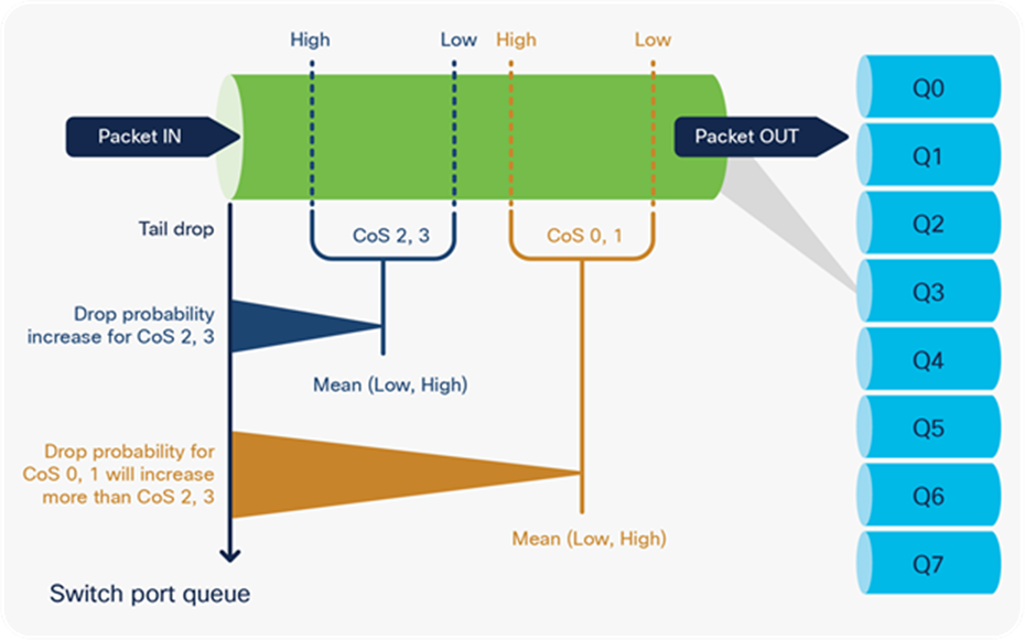
Increase in WRED drop probability
Each port queue can use only one type of WRED classification. For example, if it uses DSCP, it cannot use CoS on the same port queue. However, a different port queue on the same port can use CoS instead of DSCP.
The following is a sample MQC policy to configure WRED.
policy-map 2P6Q3T
class DATA-QUEUE
random-detect dscp-based
random-detect dscp 10 percent 60 80
class BULK-QUEUE
random-detect cos-based
random-detect cos 1 percent 60 80
Cisco Catalyst 9000 family switches support WRED as follows:
● The UADP 2.0 and 2.0 XL ASIC can enable up to four WRED queues from eight port queues.
● The UADP 3.0 ASIC supports WRED in up to eight port queues.
Regardless of the UADP ASIC version:
● Port queues that do not use WRED will use WTD.
● WRED is not supported on priority queues.
● Up to three WRED ranges are supported per class map, but one range can be used for a range of packet classifiers.
class <queuing-class-map>
random-detect cos 1 percent 10 20 (range1)
random-detect cos 2 percent 30 40 (range2)
random-detect cos 3 percent 50 60 (range3)
To summarize: Queuing, buffering, and thresholds as egress QoS tools can help to manage and prioritize business-critical traffic. But there are a few other techniques to help reduce the output drops that can occur on egress ports:
● Distribute the active ports as per their burst requirements between the UADP ASIC cores in such a way that fewer ports will share the core physical buffer space.
● Sample distribution 1: Notice that Core 1 has only one port. This model can be used when a single port needs to consume all UADP ASIC core buffer and the rest of the ports do not experience high levels of micro-bursts.
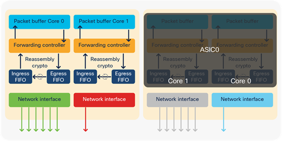
A physical port distribution in which one port can consume an entire PBC
● Sample distribution 2: Notice that all active ports are evenly distributed across all UADP ASIC cores. This model is used when all active ports have similar levels of micro-burst; hence, they can be evenly distributed across different UADP ASIC cores to balance the PBC resource usage.
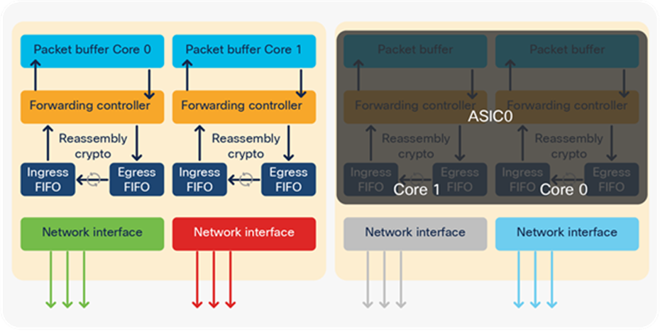
Even physical port distribution
The command to see the mapping is as follows, where front panel ports can be mapped to an instance:

● Use the command qos queue-softmax-multiplier <100-1200>. This command was discussed in the DTS section. To increase the PBC’s ability to absorb micro-bursts, use a value close to 1200.
● Reduce the total number of queues per port. For example, use three queues instead of eight. Every queue has dedicated buffer from the shared pool, which reduces the total size of the global pool. With fewer queues, the shared pool will have a larger size to share.
Shaping is an egress QoS tool that can be used to limit the packets send out of a port queue. Shaping functions differently than policing, as it will try to use any free buffer space before dropping a packet, while policing drops the packet immediately. The buffered packets will be transmitted when the port gets further transmit cycles. Figure 34 shows the differences between shaping and policing.
Starting from 17.3(1) Egress Shaping is supported based on MPLS EXP as well.
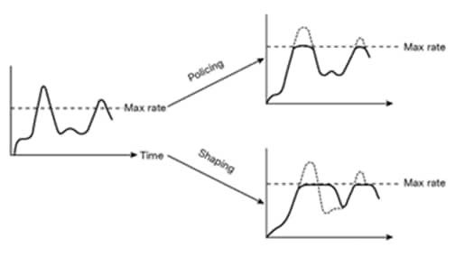
Shaping vs. policing
With shaping, a certain amount of traffic is buffered and sent out of the port when the burst disappears. Buffering adds delay to the packets as they wait to be transmitted.
The UADP ASIC offers a shaper for every port queue. The following is a sample MQC policy to configure shaping:
policy-map Shaper
class Voice
shape average percent 10
class Video
shape average percent 20
class Signaling
shape average percent 5
class Transactions
shape average percent 30
To summarize: Shaping is used primarily to control the priority queues. It limits the total bandwidth on priority queues to leave some space in WRR queues.
Egress classification, policing, and marking
Egress classification, policing, and marking are exactly the same as for ingress with a few exceptions:
● The egress marking result is not used for queuing.
● Classification is based on the original packet and on the result from the IFC.
Figure 35 shows an example of two subsequent remarks—first on ingress and second on egress, where the egress uses the ingress result instead of the original packet:
1. IFC remarked any ingress packet with DSCP 10 to 30.
2. But the EFC used an MQC policy on egress port 2 that instructs it to remark any packet with DSCP 30 to 40, while egress port 1 has kept the IFC result.
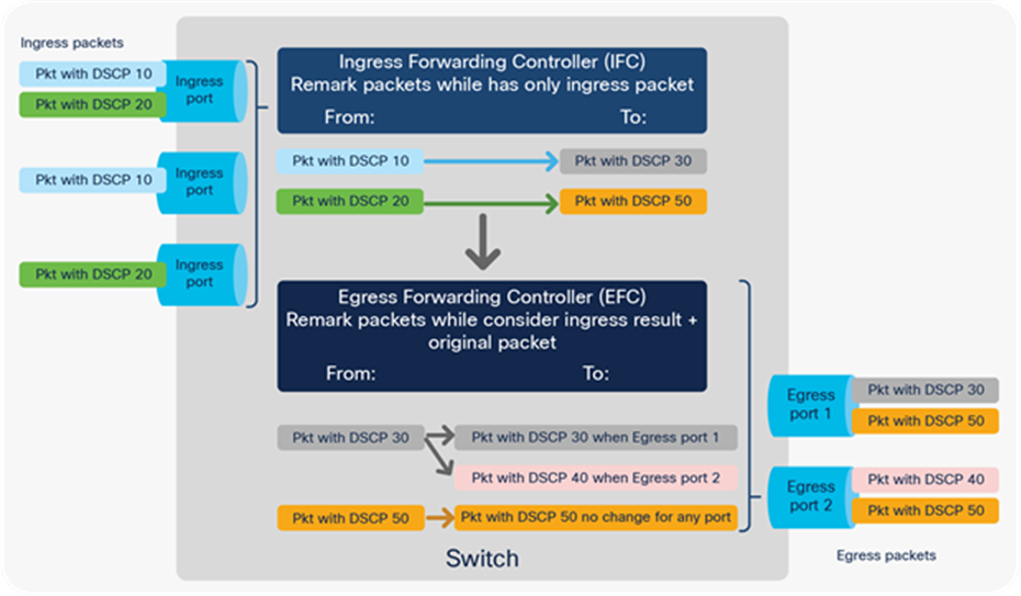
Two-stage remarking
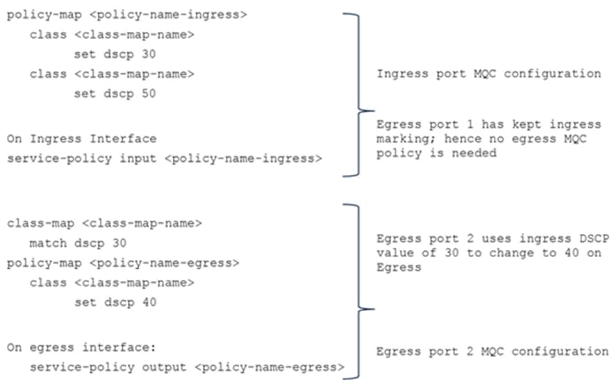
The following is a sample MQC policy to configure two-stage remarking:
|
|
|
To summarize: Egress classification, policing, and marking further extend the UADP ASIC capabilities for QoS. They provide the option to take the packets from multiple source ports and apply only a single egress MQC policy. They also provide the option to do two-stage remarking or policing.
Hierarchical QoS (HQoS) is an egress tool that allows two MQC policies to be stacked on two levels as parent and child, thus allowing for greater policy granularity. The parent policy is at the top level and the child is at the bottom level. Administrators can use HQoS to:
● Allow a parent class to shape multiple queues in a child policy
● Apply specific policy map actions to the aggregate traffic
● Apply class-specific policy map actions
One of the key advantages of Cisco Catalyst 9000 family switches is their support for HQoS in hardware.
There are four supported HQoS combinations:
● Port shaper
● Aggregate policer
● Per-port, per-VLAN policy
● Parent using shaper
Port shaper
An HQoS port shaper applies a shaper to all egress traffic using the class-default. Within this shaped bandwidth, additional child policies can be specified.
The following example demonstrates an HQoS port shaper configuration:
policy-map PARENT
class class-default
shape average percent 10
service-policy CHILD
policy-map CHILD
class VOICE
priority level 1
police rate percent 20
class C1
bandwidth remaining percent 10
class C2
bandwidth remaining percent 20
class C3
bandwidth remaining percent 70
Notes on HQoS port shaper policy:
● Only the class-default class can be used in the parent policy.
● Only one or two priority queues are allowed in the child policy.
● Different bandwidth per class in the child policy is permitted.
Aggregate policer
An HQoS aggregate policer applies to all egress traffic using the class-default. Within this policed bandwidth, additional child policies can be specified.
The following example demonstrates an HQoS aggregate policer configuration:
policy-map PARENT
class class-default
police cir percent 30
service-policy CHILD
policy-map CHILD
class C1
set dscp 10
class C2
set dscp 20
class C3
set dscp 30
Notes on the HQoS aggregate policer policy:
● A table map can be used as a set action in the child policy.
Per-port, per-VLAN policy
A per-port, per-VLAN policy applies multiple HQoS parent policers, with each policer matching a VLAN as its classifier. Within each VLAN’s individual policed bandwidth, additional child policies may be applied.
The following example demonstrates an HQoS per-port, per-VLAN configuration:
policy-map PARENT
class vlan10
police rate percent 10
service-policy CHILD
class vlan20
police rate percent 20
service-policy CHILD
class vlan30
police rate percent 30
service-policy CHILD
policy-map CHILD
class C1
set dscp 10
Notes on the HQoS per-port, per-VLAN policy:
● A table map can be used as a set action in the child policy.
● Multiple classes under a parent policy are permitted.
Parent using shaper
Multiple HQoS shapers are applied under the parent policy, with each shaper matching a traffic class. Within each individually shaped bandwidth, additional child policies may be applied.
The following example demonstrates an HQoS configuration of a parent using shapers:
policy-map PARENT
class C1
shape average percent 10
service-policy CHILD
class C3
shape average percent 20
service-policy CHILD
class class-default
shape average percent 30
service-policy CHILD
policy-map CHILD
class C1
police rate percent 10
set dscp 10
class C2
police rate percent 20
set dscp 20
class C3
police rate percent 30
set dscp 30
Notes on the HQoS parent using shaper:
● A table map can be used as a set action in the child policy.
Ingress and egress QoS tools also provide statistics on and visibility into the packets that are processed on the UADP ASIC.
Policy maps support different counters based on the actions used:
● If marking or policing is used, the policy map will collect counters indicating how many packets or bytes are mapped to a class map or dropped by the policer.
● If a queuing action is configured under the interface, the policy map supports enqueue and drop counters.
● If the same policy is shared between two or more ports, the counters are not aggregated between all ports sharing the policy.
● QoS policy-map counters are available via:
◦ Operational and configuration YANG models
◦ SNMP MIB: CiscoCBQosMIB
The following outputs provide sample counters based on different tools:
Note: The CLI outputs were collected with software release 16.9(2).
● Marking and policer policy counters (applicable for ingress and egress):
Notes:
◦ If a policy with the same name is shared on multiple ports, the policy map counters will be aggregated, as the TCAM entries are shared between the ports. As result, an interface without traffic might see increments, but the TCAM usage will be reduced, as the entries are shared.
◦ If policy-map counters are needed per port, create policy maps with different names and the TCAM entries will not be shared.
Switch# show policy-map interface <interface>
<interface>
Service-policy input: <policy-map name>
Class-map: dscp20 (match-all) à Marking Action
452651460 packets
Match: dscp af22 (20)
QoS Set
dscp af23
Class-map: dscp21 (match-all) à Policing Action
73673977 packets
Match: dscp 21
police:
cir 10 %
cir 1000000000 bps, bc 31250000 bytes
pir 20 %
pir 2000000000 bps, be 62500000 bytes
conformed 3757257000 bytes; actions:
transmit
exceeded 3758219000 bytes; actions:
set-dscp-transmit dscp table MARKDOWN
violated 29321508000 bytes; actions:
drop
conformed 96546000 bps, exceeded 96571000 bps, violated 753431000 bps
● Queuing policy counters (applicable for egress per port per queue):
Switch# show platform hardware fed [switch] [active] qos queue stats interface <interface>
DATA Port:16 Enqueue Counters
------------------------------------------------------------------------------
Queue Buffers Enqueue-TH0 Enqueue-TH1 Enqueue-TH2 Qpolicer
(Count) (Bytes) (Bytes) (Bytes) (Bytes)
--- ---- ---- ------ ----- -----
0 0 0 0 4797 0
1 0 0 0 64310 0
2 0 0 0 0 0
3 0 0 0 0 0
4 0 0 0 0 0
5 0 0 0 0 0
6 0 0 0 0 0
7 0 0 0 0 0
DATA Port:16 Drop Counters
------------------------------------------------------------------------------
Queue Drop-TH0 Drop-TH1 Drop-TH2 SBufDrop QebDrop QpolicerDrop
(Bytes) (Bytes) (Bytes) (Bytes) (Bytes) (Bytes)
-- ----- ------- ------ ------ ----- -------
0 0 0 3 0 0 0
1 0 0 87 0 0 0
2 0 0 0 0 0 0
3 0 0 0 0 0 0
4 0 0 0 0 0 0
5 0 0 0 0 0 0
6 0 0 0 0 0 0
7 0 0 0 0 0 0
● Shaper (applicable for egress per port per queue):
Switch# show policy-map interface <egress interface>
<interface>
<snip>
queue stats for all priority classes:
Queueing
priority level 2
(total drops) 9772202000 à in bytes by default
(bytes output) 2443152000
pkts output) 4910606 à switch to packets with CLI “qos queue-stats-frame-count”
● WRED (applicable for egress per port per queue):
Switch# show policy-map interface <egress-interface>
<snip>
Class-map: dscp2 (match-all)
0 packets
Match: dscp 2
Queueing
(total drops) 0
(bytes output) 0
bandwidth remaining 9%
queue-buffers ratio 9
AFD WRED STATS BEGIN
Virtual Class min/max Transmit Random drop AFD Weight
0 10 / 20 (Byte)0 0 4
(Pkts)0 0
dscp : 2
1 100/ 100 (Byte)0 0 29
(Pkts)0 0
dscp :
2 100/ 100 (Byte)0 0 29
(Pkts)0 0
dscp :
Total Drops(Bytes) : 0
Total Drops (Packets) : 0
AFD WRED STATS END
QoS and queuing for overlay technologies
This section discusses how packets that are encapsulated are processed by the UADP ASIC. The encapsulated packets have more than one IP header; hence they need to be processed differently.
Generic Routing Encapsulation (GRE) tunnels, Virtual Extensible LAN (VXLAN), and Control and Provisioning of Wireless Access Points (CAPWAP) are overlay technologies that wrap the original IP packet with external header(s) to enable the packet to be transported more efficiently or to cross multiple hops without modifying the original packet.
A GRE encapsulated packet includes the original Layer 3 packet
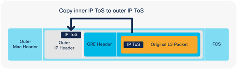
GRE encapsulated packet
In the encapsulation shown in Figure 36, the packet gets added behind a new IP header and GRE header. The ToS byte value from the inner IP header is copied to the outer IP header.
A VXLAN encapsulated packet includes the original Layer 2 frame and Layer 3 packet.
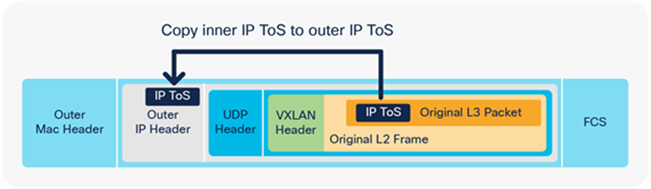
VXLAN encapsulated packet
In the encapsulation shown in Figure 37, the packet gets added behind a new IP header and VXLAN header. The ToS byte value from the inner IP header is copied to the outer IP header.
A CAPWAP encapsulated packet includes the original Layer 2 frame and Layer 3 packet:
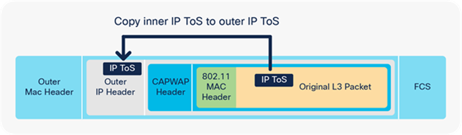
CAPWAP encapsulated packet
In the encapsulation shown in Figure 38, the packet gets added behind a new IP header and CAPWAP header. The ToS byte value from the inner IP header is copied to the outer IP header.
The UADP ASIC can add an overlay header to a packet to transport the packet as is, without any changes to the original packet. That process is called encapsulation and is done in hardware at line rate.
Figure 39 highlights packet processing for GRE, VXLAN, and CAPWAP encapsulation. The packet enters with a DSCP value of 5. It gets encapsulated and the outer IP header will have the same DSCP value of 5 as the inner header.
1. Ingress QoS policy on the physical ingress interface will classify based on the original packet. If QoS policy is applied on the physical ingress interface, it will affect the encapsulated packet and the outer header.
2. The GRE, VXLAN, or CAPWAP tunnel interface does not support QoS policies on ingress.
3. The packet is recirculated to add the outer encapsulation header.
4. The GRE, VXLAN, or CAPWAP tunnel interface does not support QoS policies on egress.
5. If QoS policy is applied on the physical egress interface where the encapsulated packet leaves:
● Classification will be used on the outer header only.
● Egress queuing will not use the modified outer header ToS value.
● Egress queuing will be based on the outer header’s ToS value, which is a copy of the inner header.
If QoS policy is not applied:
● Egress queuing will be based on the outer header’s ToS value, which is a copy of the inner header.
The inner encapsulated packet will not be modified and will not be used for classification.
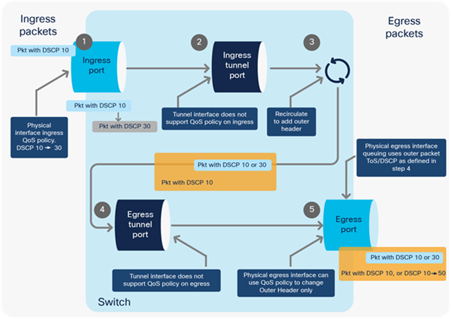
QoS processing for GRE, VXLAN, or CAPWAP encapsulation
Decapsulation path from ASIC
The UADP ASIC can remove the overlay header to deliver the inner packet to the destination. That process is called decapsulation and is processed in hardware at line rate.
Figure 40 explains how a GRE, VXLAN, or CAPWAP packet is decapsulated. After the recirculation, the outer header is discarded, and the inner IP header is used for the egress queuing interface.
1. Ingress QoS policy on the physical ingress interface will classify based on the outer header.
2. The GRE, VXLAN, or CAPWAP tunnel interface does not support QoS policies on ingress.
3. The packet is recirculated to remove the outer encapsulation header.
4. The GRE, VXLAN, or CAPWAP tunnel interface does not support QoS policies on egress.
5. If QoS policy is applied on the physical egress interface where the decapsulated packet leaves:
● Classification will be used on the decapsulated packet header.
● Egress queuing will not use the modified decapsulated header ToS value.
● Egress queuing will be based on the decapsulated packet header’s ToS value.
If QoS policy is not applied:
● Egress queuing will be based on the decapsulated packet header’s ToS value.
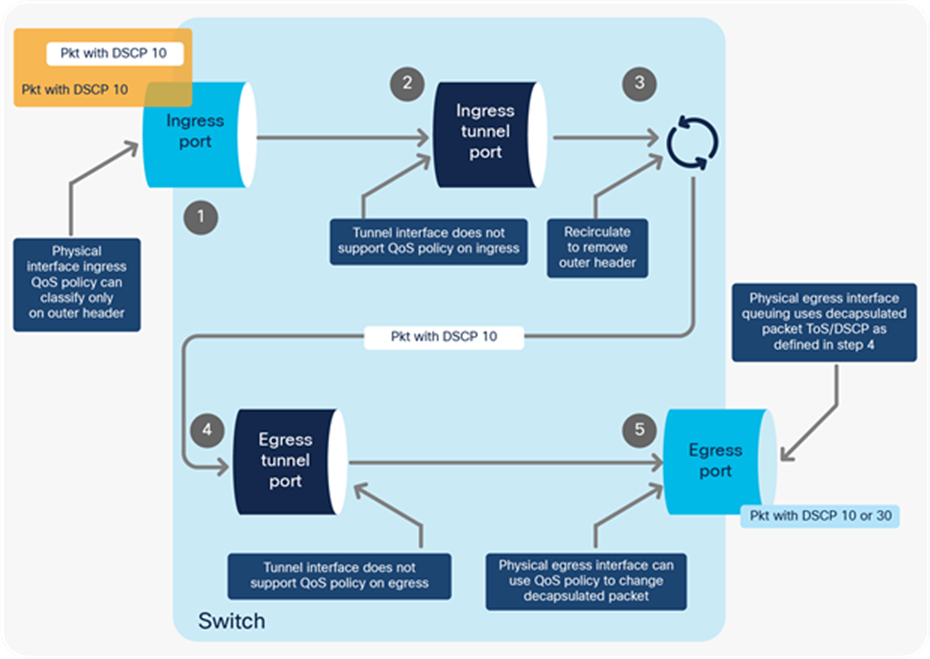
QoS processing for GRE, VXLAN, or CAPWAP decapsulation
MPLS QoS
MPLS packets have a label that is used for faster forwarding and segmentation. The UADP ASIC needs to extract the EXP marker from the header and use it for classification. The MPLS feature set is supported in the following modes:
● Pipe mode: DiffServ Tunneling Pipe mode uses two layers of QoS:
◦ An underlying QoS for the data, which remains unchanged when traversing the core.
◦ A per-core QoS, which is separate from that of the underlying IP packets. This per-core QoS Per-Hop Behavior (PHB) remains transparent to end users.
When a packet reaches the edge of the MPLS core, the egress Provider Edge (PE) switch (PE2) classifies the newly exposed IP packets for outbound queuing based on the MPLS PHB from the EXP bits of the recently removed label.

QoS processing for MPLS Pipe mode
Short Pipe mode is not supported.
● Uniform mode (the default mode): DiffServ Tunneling Uniform mode has only one layer of QoS, which reaches from end to end.
The ingress PE switch (PE1) copies the DSCP from the incoming IP packet into the MPLS EXP bits of the imposed labels. As the EXP bits travel through the core, they may or may not be modified by an intermediate P switch. In the example shown in Figure 42, P switch P1 modifies the EXP bits of the top label. At the egress P switch (P2), we copy the EXP bits to the EXP bits of the newly exposed label after the PHP (penultimate hop-pop). Finally, at the egress PE switch (PE2), we then copy the EXP bits to the DSCP bits of the newly exposed IP packet.
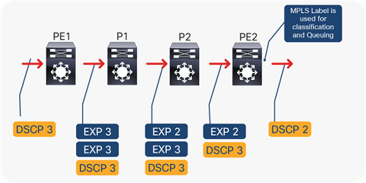
QoS processing for MPLS uniform mode
Cisco AutoQoS dramatically simplifies QoS deployment by automating QoS features for voice and/or video traffic in a consistent fashion and leveraging the advanced functionality and intelligence of Cisco IOS XE Software by using templates.
AutoQoS templates follow the RFC 4594 recommendation for marking and provisioning medianet application classes.
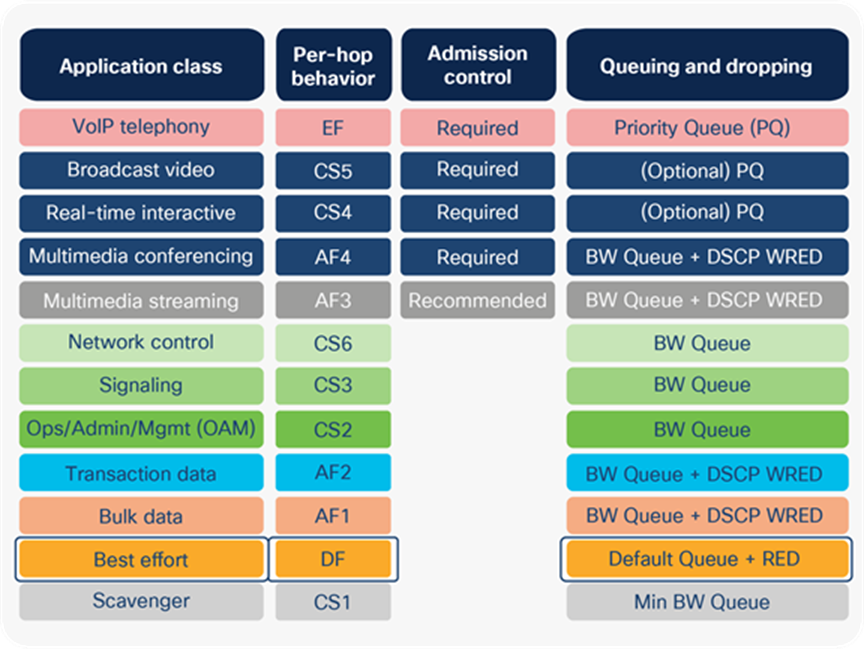
AutoQoS traffic per marker allocation
The following template has been integrated within the AutoQoS template, though not all 12 classes are always needed and used by the templates.
● auto qos trust {cos | dscp}: This option configures the port to statically trust either CoS or DSCP. If neither CoS nor DSCP is explicitly specified, the auto qos trust command will configure CoS-trust on Layer 2 switch ports and DSCP-trust on Layer 3 routed interfaces. This command has become optional on Cisco Catalyst 9000 family switches, as the default behavior is to trust the Layer 2 and Layer 3 markers.
● auto qos video [cts | ip-camera]: This option provides automatic configuration support for Cisco TelePresence® Systems (via the cts keyword) as well as for Cisco IP video surveillance cameras (via the ip-camera keyword).
● auto qos classify {police}: This option provides a generic template that can classify and mark up to six classes of medianet traffic, as well as optionally provision data-plane policing and scavenger-class QoS policy elements for these traffic classes (via the optional police keyword).
● auto qos voip [cisco-phone | cisco-softphone | trust]: This option not only provides legacy support for AutoQoS VoIP IP telephony deployments, but also expands on these models to include provisioning for additional classes of rich media applications and to include data-plane policing and scavenger-class QoS policy elements to protect and secure these applications.
Figure 44 illustrates the recommended interface trust model.
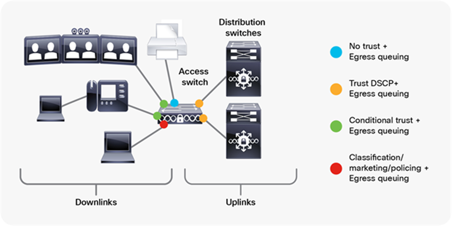
Recommended AutoQoS trust model
The conditional trust model configures the interface to dynamically accept markings from endpoints that have met a specific condition, such as a successful Cisco Discovery Protocol negotiation (switch ports set to conditional trust are shown as green circles in Figure 44).
This model is suitable for switch ports connecting to:
● Cisco IP phones: trust device cisco-phone
● Cisco TelePresence Systems: trust device cts
● Cisco IP video surveillance cameras: trust device ip-camera
● Cisco digital media players: trust device media-player
AutoQoS queuing models
Each AutoQoS option automatically provisions egress queuing models on every switch port that it is applied on.
Refer to the Cisco Catalyst 9000 QoS Configuration Guide for further information on AutoQoS.
The StackWise Virtual System (SVS) combines two physical switches into a single logical switch system. One of the components of SVS is the StackWise Virtual Link (SVL). This section discusses QoS and queuing behavior on the SVL.
● The SVL QoS and queuing mechanism is hardcoded.
● The QoS and queuing policy for the SVL cannot be modified.
Figure 45 shows SVL marker allocation per queue.
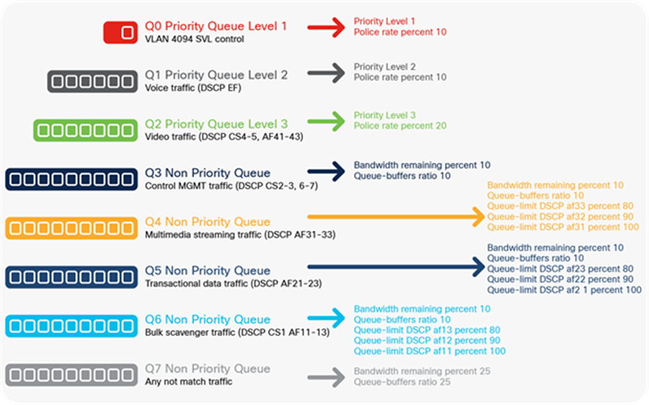
SVL traffic per queue on SVL ports
The Cisco Catalyst 9000 switch family has a special set of queues that manage the access to the CPU. This set of queues can ensure that priority packets are received first.
Packets destinated for the CPU will follow the normal ingress data forwarding path. Depending on the packet type, they will enter one of the CPU queues. Every CPU queue has a predefined policer to protect the CPU. This is commonly referred as Control Plane Policing (CoPP).
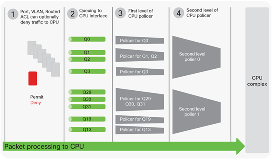
Packet processing to CPU
There are four steps before a packet reaches the CPU:
1. If traffic should never reach the CPU, an ingress ACL can be used to deny that traffic. This step is optional. Different ACL types are supported, such as port, VLAN, and routed ACL.
2. The packet is classified based on CoPP policy and placed into CPU queues. This step ensures that priority traffic can reach out first.
3. Traffic is reduced per the specified first level of policing rates. Some of the policers are shared.
4. Finally, high- and low-level policers are added. The two-level aggregate first-level classes can additionally reduce the rate. A second level of policer is added in Cisco IOS XE 16.9 and later.
The following restrictions apply with CoPP:
● Only ingress CoPP is supported. The system-cpp-policy policy map is available on the control plane interface only in the ingress direction.
● Only the system-cpp-policy policy map can be installed on the control plane interface.
● The system-cpp-policy policy map and the 17 system-defined classes cannot be modified or deleted.
● Only the police action is allowed under the system-cpp-policy policy map. Further, the police rate can be configured only in packets per second (pps).
● Enabling or disabling CPU queues:
◦ Enable a CPU queue by configuring a policer action (in pps) under the corresponding class map, within the system-cpp-policy policy map.
◦ Disable a CPU queue by removing the policer action under the corresponding class map, within the system-cpp-policy policy map.
● Set the CPU queues to their default values by entering the cpp system-default command in global configuration mode.
● CoPP uses two hierarchical levels (introduced in Cisco IOS XE 16.9 and later).
● Custom CoPP profiles or custom classes are not supported.
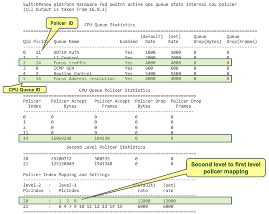
Reviewing the output of the CoPP policy
From-CPU originated packets
Packets generated by the CPU are sent directly to the egress queues.
When you define a queuing policy on a port, control packets are mapped to a queue with the following order:
1. The highest-level priority queue is always chosen first.
2. In the absence of a priority queue, queue 0 is selected.
In the second case, where queue 0 is selected, you must assign the highest bandwidth to this queue to get the best QoS treatment for the CPU-generated traffic.
Next, we will discuss LACP PDUs, which are a packet type that has no priority built in.
Sample policy:
First case: policy-map <name>
class <name>
priority level 1 à LACP packets will go in this queue
Second case: policy-map <name>
class <name associated with queue 0>
à LACP packets will go in queue 0 as priority queue is not defined
Finally, if packets originate from the CPU, and egress QoS policy with ACL classification is applied on a Layer 2 port or routed interface, the policy will be able to remark these packets. But if DSCP, CoS, or traffic class is used to classify packets that originate from the CPU, QoS policy will not remark these packets.
Cisco Catalyst 9000 family switches offer flexible techniques to change and adjust the device hardware resource for QoS and queuing. These techniques provide application and user traffic with a wide variety of options to adapt to changes over time.
The following websites offer more detailed information about the Cisco Catalyst 9000 family and capabilities:
Overview of the Cisco Catalyst 9000 family:
https://www.cisco.com/c/en/us/products/switches/catalyst-9000.html.
Per model:
https://www.cisco.com/c/en/us/products/switches/catalyst-9200-series-switches/index.html.
https://www.cisco.com/c/en/us/products/switches/catalyst-9300-series-switches/index.html.
Appendix A: Classification in TCAM
This section describes the hardware programming inside the ASIC with the corresponding QoS policy.
What are TCAM tables? What are VCUs?
TCAM (ternary content-addressable memory) is a specialized type of high-speed memory that searches its entire contents in a single clock cycle. The term “ternary” refers to the memory’s ability to store and query data using three different inputs: 0, 1, and X.
VCUs (value comparing units) are special registers used to scale the Layer 4 operations in the TCAM. They are linked from the TCAM and can be shared between multiple TCAM entries. Layer 4 operations that use the VCU register are less than (LT), Greater Than (GT), or range or not equal (nor). Equal (EQ) is not considered a Layer 4 operator that uses VCUs.
The classification process uses TCAM tables. The TCAM table is preprogrammed based on the MQC policy. The tables include a matching entry for every required classification.
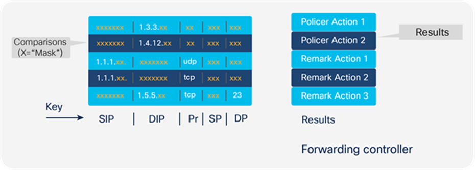
TCAM lookup (step 1)
The switch uses a packet header or markers to generate a hash key, which is matched to an entry that can give the policer or remarked value.
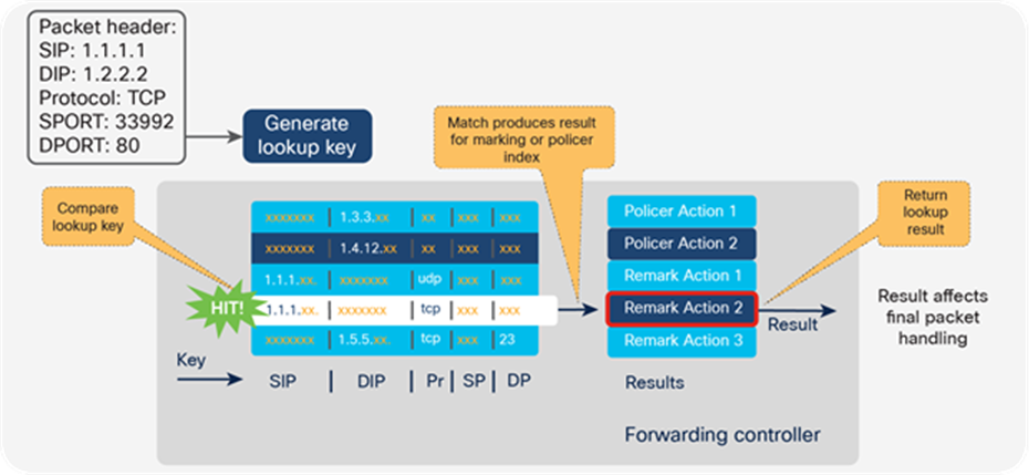
TCAM lookup (step 2)
Once the result is found, the switch can apply the required actions:
● Policer
● Marking
● Markdown
● Mutation
QoS ACL uses a different number of VCUs, depending on the Layer 4 operation:
● Not Equal (NE) consumes one VCU.
● Range consumes two VCUs, as it has low and high values.
● Greater Than (GT) and Less Than (LT) consume one VCU.
● Source and destination Layer 4 operations consume separate VCUs.
Figure 50 illustrates VCU utilization.
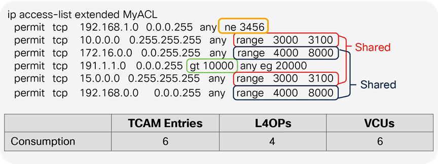
TCAM-to-VCU mapping
VCU entries will be reused if the ACL uses the same range of ports on multiple TCAM entries (access list entry ACE).
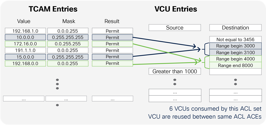
Table 4 lists UADP ASIC scale information.
Table 4. UADP ASIC scalability for QoS
| Quality of Service UADP scale |
UADP Mini |
UADP 2.0 |
UADP 2.0 XL |
UADP 3.0 |
| Used in Catalyst switch |
Cat 9200 |
Cat 9300 |
Cat 9300, 9400, 9500 |
Cat 9500 High, 9600 |
| Class-maps (Ingress) per policy |
256 |
256 |
256 |
256 |
| Class-maps (egress) per policy |
256 |
256 |
256 |
256 |
| Policers (Ingress) per policy |
63 |
63 |
63 |
63 |
| Policers (engress) per policy |
63 |
63 |
63 |
63 |
| Total Policy-maps per switch |
1599 |
1599 |
1599 |
1599 |
| Aggregate Policers 1R2C per Core |
1024 |
4096 |
4096 |
4096 |
| Aggregate Policers 2R3C per Core |
512 |
2048 |
2048 |
2048 |
| Table-maps (ingress) |
16 |
16 |
16 |
16 |
| Table-maps (egress) |
16 |
16 |
16 |
16 |
| Markdown table (exceed action) |
8 |
8 |
8 |
8 |
| Markdown table (Violate action) |
8 |
8 |
8 |
8 |
| Egress Queues per port |
8 |
8 |
8 |
8 |
| Buffer per Core (MB) |
6 |
8 |
16 |
18 |
| Buffer per ASIC (MB) |
6 |
16 |
32 |
36 |
| QoS ACLs per Core |
1000 |
5000 |
18000 |
16000 |
| QoS ACLs per Core per Direction |
1000 |
5000 |
18000 |
8000 |
| WRED (Up to Queues) |
NA |
4 |
4 |
8 |
| VCU (ingress) |
192 |
192 |
192 |
192 |
| VCU (egress) |
96 |
96 |
96 |
96 |
QoS TCAM consumption rules:
● UADP 2.0 and 2.0 XL, UADP Mini
◦ IPv4 ACL consumes one ACE entry.
◦ IPv6 ACL consumes two ACE entries.
◦ If a class map that matches on DSCP is used, three ACE entries will be installed: one for IPv4 and two for IPv6.
● UADP 3.0
◦ IPv4 ACL consumes one ACE entry.
◦ IPv6 ACL consumes one ACE entry.
◦ If a class map that matches on DSCP is used, two ACE entries will be installed: one for IPv4 and one for IPv6.
Appendix C: Detailed packet format
The following figures show how to read and where to find the markers inside packets in different captures.
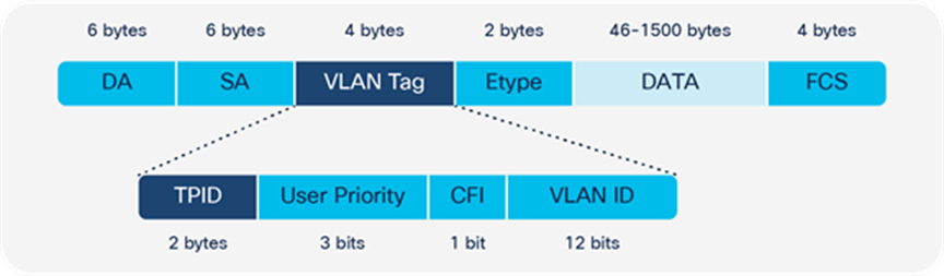
Layer 2 CoS (user priority) packet format
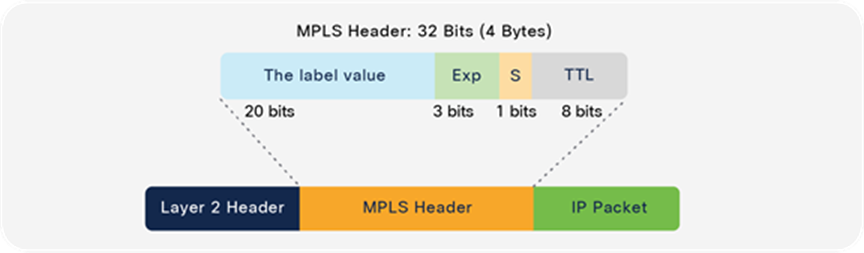
MPLS EXP packet format
Type of Service (ToS) is a 1-byte field that exists in an IPv4 header. A similar byte is used in an IPv6 header and is called traffic class.
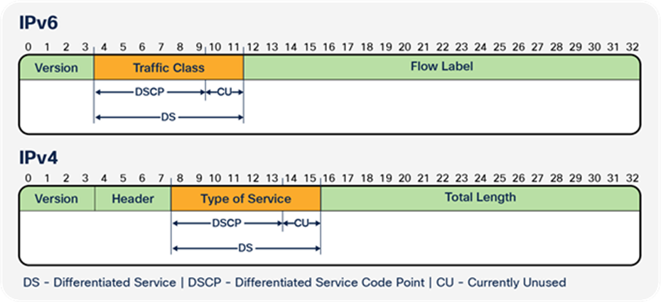
Layer 3 IP Precedence (ToS) and DSCP Packet Format
The ToS field consists of eight bits, of which the first three bits indicate the priority of the IP packet. These first three bits are referred to as the IP precedence bits, with values from 0 to 7 (0 is the lowest priority and 7 is the highest). Support for setting IP precedence in Cisco IOS XE has been around for many years. Figure 54 is a representation of the IP precedence bits in the ToS header.
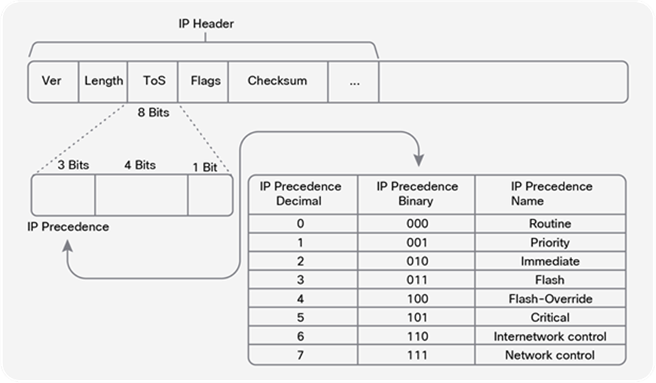
How to read the ToS byte as IP precedence
The same ToS byte can be read in DSCP or traffic class format, which uses six bits.
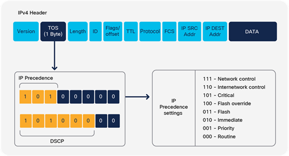
Comparison between DSCP and IP precedence
● The three Most Significant Bits (MSB) are interpreted in the same way as the IP precedence bits.
● The three Least Significant Bits (LSB) from the DSCP bits are interpreted as drop probability.
● The last two bits from the ToS byte are the Explicit Congestion Notification (ECN). The ECN bits are not used by the Cisco Catalyst 9000 switch family.