IP Mobility: Mobile Networks Configuration Guide, Cisco IOS Release 15M&T
Bias-Free Language
The documentation set for this product strives to use bias-free language. For the purposes of this documentation set, bias-free is defined as language that does not imply discrimination based on age, disability, gender, racial identity, ethnic identity, sexual orientation, socioeconomic status, and intersectionality. Exceptions may be present in the documentation due to language that is hardcoded in the user interfaces of the product software, language used based on RFP documentation, or language that is used by a referenced third-party product. Learn more about how Cisco is using Inclusive Language.
Open Shortest Path First version 3 (OSPFv3) Extensions optimize OSPFv3 behavior for more efficient routing in Mobile Ad Hoc
Networks (MANETs). The OSPFv3 extensions improve routing efficiency and reduce overhead traffic in MANET environments so that
network clusters can scale to support more users. The OSPFv3 extensions boost performance for delay-sensitive, mission-critical
voice, video, and data traffic, and it facilitates the integration of wireless MANETs with existing wire-line products.
Finding Feature Information
Your software release may not support all the features documented in this module. For the latest caveats and feature information,
see Bug Search Tool and the release notes for your platform and software release. To find information about the features documented in this module,
and to see a list of the releases in which each feature is supported, see the feature information table.
Use Cisco Feature Navigator to find information about platform support and Cisco software image support. To access Cisco Feature
Navigator, go to www.cisco.com/go/cfn. An account on Cisco.com is not required.
Prerequisites for OSPFv3 Extensions for MANETs
You must create the subscriber profile for PPP over Ethernet (PPPoE) service selection, assign the subscriber profile to a
PPPoE profile, and enable PPPoE sessions on the interface. For details, see the "Mobile Ad Hoc Networks for Router-to-Radio
Communications" module.
Information About OSPFv3 Extensions for MANETs
OSPFv3 Extensions Operation with MANETs
To optimize the use of OSPFv3 with MANETs, Cisco software implements extensions to OSPFv3 as defined in draft-chandra-ospf-manet-ext-02
. The result is a well-understood routing protocol (OSPF) used in a network topology that is constantly changing and where
bandwidth is limited.
OSPF is optimized in these ways:
Tightly couples OSPFv3 with Radio Aware Routing (RAR)-compliant radios to provide faster convergence and reconvergence through
neighbor presence indications and help determine accurate, real-time link metric costs.
Minimizes OSPFv3 packet size by implementing incremental hellos.
Minimizes the number of OSPFv3 packet transmissions by caching multicast link-state advertisements (LSAs).
Implements optimized flooding (overlapping relay) functionality to minimize the number of flooded LSAs.
Implements selective peering to reduce the OSPF network overhead by minimizing the number of redundant full adjacencies that
an OSPF node maintains.
Radio-Aware Link-Metrics Tuning for OSPFv3
The RAR-compliant radio reports link-quality metrics to the router that are used by OSPFv3 as link metrics. You can fine-tune
to adjust how these radio metrics are used by OSPFv3:
Configure how the radio-reported bandwidth, latency, resource, and relative link-quality metrics are converted to an OSPFv3
link cost.
Configure a hysteresis threshold on this resultant link cost to minimize the propagation of LSAs that report link-metric changes.
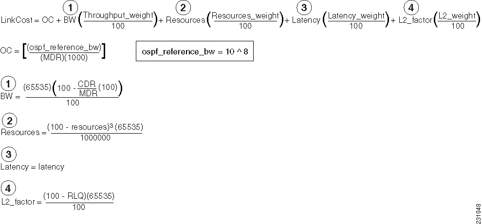
OSPFv3 receives raw radio-link data and computes a composite. In computing these metrics, you should consider these factors
(see the figure "OSPF Cost Calculation for VMI Interfaces"):
Maximum data rate--the theoretical maximum data rate of the radio link, in bytes per second
Current data rate--the current data rate achieved on the link, in bytes per second
Resources--a percentage (0 to100) that can represent the remaining amount of a resource (such as battery power)
Latency--the transmission delay packets encounter, in milliseconds
Relative link quality (RLQ)--a numeric value (0 to 100) representing relative quality, with 100 being the highest quality
You can weight metrics during the configuration process to emphasize or de-emphasize particular characteristics. For example,
if throughput is a particular concern, you can weight the current data rate metric so that it is factored more heavily into
the composite metric. Similarly, you can omit a metric that is of no concern from the composite calculation.
Link metrics can change rapidly, often by very small degrees, which can result in a flood of meaningless routing updates.
In a worst-case scenario, the network churns almost continuously as it struggles to react to minor variations in link quality.
To alleviate this concern, you can use a tunable dampening mechanism to configure threshold values. Any metric change that
falls below the threshold is ignored.
With the tunable hysteresis mechanism, you can adjust the threshold to the routing changes that occur when the router receives
a signal that a new peer has been discovered, or that an existing peer is unreachable. The tunable metric is weighted and
is adjusted dynamically to account for these characteristics:
Current and maximum bandwidth
Resources
Latency
Hysteresis
You can deconfigure individual weights and clear all weights so that the cost is returned to the default value for the interface
type. Based on the routing changes that occur, the cost can be determined by the application of these metrics.
Dynamic Cost Metric for Virtual Multipoint Interfaces
The dynamic cost metric used for virtual multipoint interfaces (VMIs) is computed based on the Layer 2 (L2) feedback to Layer
3 (L3). The dynamic cost is calculated using this formula:
For a dynamic cost to have the same cost as a default cost, all parameters must equal zero.
Each Layer 2 feedback can contribute a cost in the range of 0 to 65535. To tune down this cost range, use the optional
weight keyword with the
throughput,
resources,
latency, or
L2-factor keyword with the
ospfv3cost command. Each of these weights has a default value of 100 percent and can be configured in the range from 0 to 100. When
0 is configured for a specific weight, that weight does not contribute to the OSPF cost.
Because cost components can change rapidly, you might need to dampen the number of changes to reduce network-wide churn.
Use the optional
hysteresis keyword with the
thresholdthreshold-value keyword and argument with the
ospfv3cost command to set a cost change threshold. Any cost change below this threshold is ignored.
You can use the
hysteresis keyword to specify a hysteresis value based on the percentage of change of the currently stored value in the routing table
for the peer.
Each time the router receives a new packet discovery quality (PADQ) packet from the radio for a peer, a new cost is calculated
for it. The
hysteresis keyword specifies the amount of change required before the router saves the new value.
The hysteresis percent calculated is performed as follows:
If the absolute value of (new_cost - saved_cost) is greater than (hysteresis_percent*saved_cost), then the new_cost is saved.
Because cost components can change rapidly, you might need to dampen the volume of changes to reduce network-wide churn.
The recommended values for S2, S3, and S4 are based on network simulations that might reduce the rate of network changes.
The recommended value for S1 is zero to eliminate this variable from the route cost calculation.
Each network might have unique characteristics that require different settings to optimize actual network performance, the
table below lists the recommended cost settings intended as a starting point for optimizing an OSPFv3 network.
Table 1. Recommended Value Settings for OSPF Cost Metrics
Setting
Metric Command
Default Value
Recommended Value
S1
ospfv3 6 cost dynamic weight throughout
100
0
S2
ospfv3 6 cost dynamic weight resources
100
29
S3
ospfv3 6 cost dynamic weight latency
100
29
S4
ospfv3 6 cost dynamic weight L2-factor
100
29
The overall link cost is computed by using the formula shown in the figure below.
Figure 1. OSPF Cost Calculation for VMI Interfaces
To illustrate these settings, the following example shows how OSPF cost metrics might be defined for a VMI interface with
one type of radio:
Selective peering reduces the OSPF network overhead by minimizing the number of redundant full adjacencies that an OSPF node
maintains. Adjacencies to nodes that do not provide additional reachability can be kept in a two-way state. Selective peering
reduces control-plane bandwidth utilization by reducing the number of database exchanges and routing updates.
Note
Dataplane connectivity is not reduced when selective peering is enabled. User traffic flows over two-way links if they provide
the best path through the network.
In the simplest example, selective peering determines if an adjacency should be formed when a new neighbor is discovered (a
hello is received from a new neighbor). If the neighbor is not in the OSPF link state database, or if it is not reachable
in the Shortest Path Tree (SPT), then the adjacency is formed. If the neighbor is in the OSPF link state database and is reachable,
the neighbor is kept in the two-way state if the configured number of redundant paths to this neighbor is already formed.
Topology changes might cause the number of redundant paths to a given neighbor to fall below the configured level. When this
occurs, selective peering can bring up adjacencies that were previously kept in the two-way state.
Selective peering takes link cost into consideration when determining which adjacencies to form. The objective is to have
the reduced numbers of adjacencies formed over the lowest cost links. You can manually configure per-neighbor OSPF link costs,
but with RAR-compliant radio interfaces, link costs are dynamically obtained from the radio through the VMI.
Selective Peering Link-Metrics Tuning
If the configured selective peering redundancy level is greater than 0,
then at least two OSPFv3 control plane paths are maintained for every one hop
neighbor. As new neighbors are discovered, full peering relationships are
formed regardless of the link cost (as long as the cost satisfies the
optionally configured minimum threshold specified in the
ospfv3manetpeeringlink-metrics command).
As additional neighbors are brought to the full peering state to
achieve the configured number of redundant paths to every neighbor, the router
evaluates the path costs resulting from these new peering relationships to
determine if they are incrementally better than the existing path costs. If
they are not, the router keeps these links in a two-way state until other
peering opportunities arise. The result is better path costs.
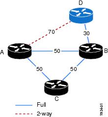
Consider the topology shown in the figure below. The configured
redundancy level is 1 (the default), meaning that Router A attempts to maintain
two paths to every one hop neighbor. Router A is in a full peering relationship
with Router B and the link cost is 50. Router B is in a full peering
relationship with Router D and the link cost is 30. Now Router D comes into
radio range of Router A with a link cost of 70. Because the number of paths
from Router A to Router D is currently 1 (through Router B), Router A brings
this relationship to the full state.
Figure 2. Selective Peering with Link Metrics
You can keep Routers A and D in a two-way state until the link cost
between them improves, or until another router comes into range that has better
link costs to both of them. This can be achieved by configuring a redundant
path cost threshold. In the figure above, if a redundant path cost threshold of
20 is configured, then Routers A and D will not transition to the full state
until their link cost falls below the current path cost of 80 (50 + 30) minus
20, or 60. Because the depicted path cost is 70, the routers remain in the
two-way state.
How to Configure OSPFv3 Extensions for MANETs
Configuring OSPFv3 in MANETs for Radio-Aware Routing
Perform this required task to create the VMI interface for OSPFv3 and associate it with the interface on which PPPoE is enabled.
For OSPFv3 to take advantage of radio feedback, you must configure OSPFv3 MANET on the VMI. By default, VMI uses neighbor
presence and link-metric data from the radio.
Specifies IPv6 unicast address prefixes and enters address family configuration mode.
Step 9
exit
Example:
Router(config-router-af)# exit
Returns to router configuration mode.
Step 10
exit
Example:
Router(config-router)# exit
Returns to global configuration mode.
Step 11
interfacevirtual-templatenumber
Example:
Router(config)#

interface virtual-template 1
Enters interface configuration mode and creates a virtual template interface that can be configured and applied dynamically
to virtual access interfaces.
Step 12
ipv6enable
Example:
Router(config-if)# ipv6 enable
Enables IPv6 processing on the virtual template.
Step 13
nokeepalive
Example:
Router(config-if)# no keepalive
Turns off PPP keepalive messages.
Step 14
exit
Example:
Router(config-if)# exit
Returns to global configuration mode.
Step 15
interfacetypenumber
Example:
Router(config)# interface vmi 1
Creates a VMI interface, and enters interface configuration mode.
Step 16
ipv6enable
Example:
Router(config-if)# ipv6 enable
Enables IPv6 processing on the VMI interface that is not configured with an explicit IPv6 address.
Enables selective peering only for instances of the OSPF process for which the corresponding interface has been configured
with the ospfv3networkmanet command.
(Optional) redundancyredundancy-count--Changes the preferred number of redundant paths to any given peer.
(Optional) per-interface--Applies selective peering on a per-interface basis.
Step 7
end
Example:
Router(config-router)# end
(Optional) Returns to privileged EXEC mode.
Preventing Full Peering with Neighbors with Poor Link Metrics
An RAR-compliant radio might not advertise link metrics to the router before a new OSPFv3 neighbor is discovered. You can
configure OSPFv3 to wait for link metrics before considering a neighbor for OSPFv3 peering. You can specify a minimum metric
threshold. If the radio-reported link metric is above this threshold, the neighbor will be held in two-way state. With this
configuration, full peering with neighbors with poor link metrics can be effectively prevented.
Configures an OSPFv3 process to wait for link metrics from a neighbor before attempting selective peering with that neighbor.
(Optional) threshold--Specifies that the link cost computed from the received link metrics from the radio must be below this value. Otherwise,
the neighbor is held in a two-way state until metrics are received that result in a link cost below the configured level.
The range is 0 to 65535.
Sets a minimum cost change threshold necessary before a new neighbor is considered for selective peering.
Requires redundant paths to have an incrementally better path cost than the current best path cost specified either as an
absolute value or as a percentage of the current best path cost.
Step 5
end
Example:
Router(config-if)# end
(Optional) Returns to privileged EXEC mode.
Configuration Examples for OSPFv3 Extensions for MANETs
Example Configuring OSPFv3 in MANETs for Radio-Aware Routing
This example shows how to configure OSPFv3 in MANETs for use with RAR-compliant radios. For OSPFv3 to take advantage of radio
feedback, OSPFv3 MANET is configured on the VMI.
!
service timestamps debug datetime msec
service timestamps log datetime msec
no service password-encryption
service alignment detection
!
hostname Router1
!
boot-start-marker
boot-end-marker
!
no aaa new-model
!
ipv6 unicast-routing
ipv6 cef
subscriber authorization enable
!
subscriber profile pppoe_group_1
 pppoe service manet_radio
!
multilink bundle-name authenticated
!
no virtual-template subinterface
!
bba-group pppoe pppoe_group_1
 virtual-template 1
 service profile pppoe_group_1
!
interface Ethernet 0/1
 no ip address
 shutdown
!
interface Ethernet 0/2
 no ip address
 shutdown
!
interface Ethernet 0/3
 no ip address
 shutdown
!
interface Virtual-Template1
 no ip address
 ipv6 enable
 no peer default ip address
 no keepalive
!
interface vmi1
 no ip address
 ipv6 enable
 ospfv3 1 network manet
 ospfv3 1 area 0 ipv6
 physical-interface FastEthernet 0/0
!
ip forward-protocol nd
!
router ospfv3 1
!
log-adjacency-changes
address-family ipv6 unicast
exit-address-family
!
control-plane
!
line con 0
 exec-timeout 0 0
 line aux 0
 line vty 0 4
 login
!
Example Fine-Tuning Radio-Aware Routing Link Metrics
This example shows the OSPFv3 extensions for MANET configuration with fine-tuning radio-aware routing link metrics:
!
version 15.2
service timestamps debug uptime
service timestamps log uptime
no service password-encryption
!
hostname Router1
!
boot-start-marker
boot-end-marker
!
no aaa new-model
!
ip cef
ipv6 unicast-routing
ipv6 cef
!
subscriber authorization enable
!
subscriber profile pppoe_group_1
 pppoe service manet_radio
!
multilink bundle-name authenticated
!
no virtual-template subinterface
!
bba-group pppoe pppoe_group_1
 virtual-template 1
 service profile pppoe_group_1
!
interface Ethernet 0/0
 no ip address
 pppoe enable group pppoe_group_1
!
interface Ethernet 0/1
 no ip address
 shutdown
!
interface Ethernet 0/2
 no ip address
 shutdown
!
interface Ethernet 0/3
 no ip address
 shutdown
!
interface Virtual-Template1
 no ip address
 ipv6 enable
 no peer default ip address
 no keepalive
!
interface vmi1
 no ip address
 ipv6 enable
 ospfv3 1 area 0 ipv6
 ospfv3 1 network manet
 ospfv3 1 cost dynamic hysteresis threshold 1000
 ospfv3 1 cost dynamic weight throughput 0
 ospfv3 1 cost dynamic weight latency 29
 ospfv3 1 cost dynamic weight L2-factor 29
 ospfv3 1 area 0 ipv6 instance 1
 physical-interface Ethernet 0/1
!
router ospfv3 1
 router-id 10.1.1.1
 timers throttle spf 1000 2000 2000
 !
 address-family ipv6 unicast
 exit-address-family
!
ip forward-protocol nd
!
!
no ip http server
no ip http secure-server
!
logging esm config
!
!
control-plane
!
line con 0
 logging synchronous
line aux 0
line vty 0 4
 login
!
end
Example Enabling Selective Peering
This example shows the OSPFv3 extensions for MANET configuration when selective peering is enabled:
!
version 15.2
service timestamps debug uptime
service timestamps log uptime
no service password-encryption
!
hostname Router1
!
boot-start-marker
boot-end-marker
!
no aaa new-model
!
ip cef
ipv6 unicast-routing
ipv6 cef
!
subscriber authorization enable
!
subscriber profile pppoe_group_1
 pppoe service manet_radio
!
multilink bundle-name authenticated
!
no virtual-template subinterface
!
bba-group pppoe pppoe_group_1
 virtual-template 1
 service profile pppoe_group_1
!
interface Ethernet 0/0
 no ip address
 pppoe enable group pppoe_group_1
!
interface Ethernet 0/1
 no ip address
 shutdown
!
interface Ethernet 0/2
 no ip address
 shutdown
!
interface Ethernet 0/3
 no ip address
 shutdown
!
interface Virtual-Template1
 no ip address
 ipv6 enable
 no peer default ip address
 no keepalive
!
interface vmi1
 no ip address
 ipv6 enable
 ospfv3 1 area 0 ipv6
 ospfv3 1 network manet
 ospfv3 1 cost dynamic hysteresis threshold 1000
 ospfv3 1 cost dynamic weight throughput 0
 ospfv3 1 cost dynamic weight latency 29
 ospfv3 1 cost dynamic weight L2-factor 29
 ospfv3 1 area 0 ipv6 instance 1
 physical-interface Ethernet 0/1
!
router ospfv3 1
 router-id 10.1.1.1
 manet peering selective
 timers throttle spf 1000 2000 2000
 !
 address-family ipv6 unicast
 exit-address-family
!
ip forward-protocol nd
!
!
no ip http server
no ip http secure-server
!
logging esm config
!
!
control-plane
!
line con 0
 logging synchronous
line aux 0
line vty 0 4
 login
!
end
Example Preventing Full Peering with Neighbors with Poor Link Metrics
This example shows the OSPFv3 extensions for MANET configuration to prevent full peering with neighbors with poor link metrics:
!
version 15.2
service timestamps debug uptime
service timestamps log uptime
no service password-encryption
!
hostname Router1
!
boot-start-marker
boot-end-marker
!
no aaa new-model
!
ip cef
ipv6 unicast-routing
ipv6 cef
!
subscriber authorization enable
!
subscriber profile pppoe_group_1
 pppoe service manet_radio
!
multilink bundle-name authenticated
!
no virtual-template subinterface
!
bba-group pppoe pppoe_group_1
 virtual-template 1
 service profile pppoe_group_1
!
interface Ethernet 0/0
 no ip address
 pppoe enable group pppoe_group_1
!
interface Ethernet 0/1
 no ip address
 shutdown
!
interface Ethernet 0/2
 no ip address
 shutdown
!
interface Ethernet 0/3
 no ip address
 shutdown
!
interface Virtual-Template1
 no ip address
 ipv6 enable
 no peer default ip address
 no keepalive
!
interface vmi1
 no ip address
 ipv6 enable
 ospfv3 1 area 0 ipv6
 ospfv3 1 network manet
 ospfv3 1 cost dynamic hysteresis threshold 1000
 ospfv3 1 cost dynamic weight throughput 0
 ospfv3 1 cost dynamic weight latency 29
 ospfv3 1 cost dynamic weight L2-factor 29
 ospfv3 1 manet peering link-metrics 200
 ospfv3 1 area 0 ipv6 instance 1
 physical-interface Ethernet 0/1
!
router ospfv3 1
 router-id 10.1.1.1
 manet peering selective
timers throttle spf 1000 2000 2000
 !
 address-family ipv6 unicast
 exit-address-family
!
ip forward-protocol nd
!
!
no ip http server
no ip http secure-server
!
logging esm config
!
!
control-plane
!
line con 0
 logging synchronous
line aux 0
line vty 0 4
 login
!
end
Example Fine-Tuning Selective Peering with Link Metrics
This example shows the OSPFv3 extensions for MANET configuration to fine-tune selective peering with link metrics:
!
version 15.2
service timestamps debug uptime
service timestamps log uptime
no service password-encryption
!
hostname Router1
!
boot-start-marker
boot-end-marker
!
no aaa new-model
!
ip cef
ipv6 unicast-routing
ipv6 cef
!
subscriber authorization enable
!
subscriber profile pppoe_group_1
 pppoe service manet_radio
!
multilink bundle-name authenticated
!
no virtual-template subinterface
!
bba-group pppoe pppoe_group_1
 virtual-template 1
 service profile pppoe_group_1
!
interface Ethernet 0/0
 no ip address
 pppoe enable group pppoe_group_1
!
interface Ethernet 0/1
 no ip address
 shutdown
!
interface Ethernet 0/2
 no ip address
 shutdown
!
interface Ethernet 0/3
 no ip address
 shutdown
!
interface Virtual-Template1
 no ip address
 ipv6 enable
 no peer default ip address
 no keepalive
!
interface vmi1
 no ip address
 ipv6 enable
 ospfv3 1 area 0 ipv6
 ospfv3 1 network manet
 ospfv3 1 cost dynamic hysteresis threshold 1000
 ospfv3 1 cost dynamic weight throughput 0
 ospfv3 1 cost dynamic weight latency 29
 ospfv3 1 cost dynamic weight L2-factor 29
 ospfv3 1 manet peering cost percent 10
 ospfv3 1 manet peering link-metrics 200
 ospfv3 1 area 0 ipv6 instance 1
 physical-interface Ethernet 0/1
!
router ospfv3 1
 router-id 10.1.1.1
 manet peering selective
timers throttle spf 1000 2000 2000
 !
 address-family ipv6 unicast
 exit-address-family
!
ip forward-protocol nd
!
!
no ip http server
no ip http secure-server
!
logging esm config
!
!
control-plane
!
line con 0
 logging synchronous
line aux 0
line vty 0 4
 login
!
end
PPP over Ethernet (PPPoE) Extensions for Credit Flow and Link Metrics
RFC 5820
Extensions to OSPF to Support Mobile Ad Hoc Networks
Technical Assistance
Description
Link
The Cisco Support and Documentation website provides online resources to download documentation, software, and tools. Use
these resources to install and configure the software and to troubleshoot and resolve technical issues with Cisco products
and technologies. Access to most tools on the Cisco Support and Documentation website requires a Cisco.com user ID and password.
Feature Information for OSPFv3 Extensions for MANETs
The following table provides release information about the feature or features described in this module. This table lists
only the software release that introduced support for a given feature in a given software release train. Unless noted otherwise,
subsequent releases of that software release train also support that feature.
Use Cisco Feature Navigator to find information about platform support and Cisco software image support. To access Cisco
Feature Navigator, go to www.cisco.com/go/cfn. An account on Cisco.com is not required.
Table 2. Feature Information for OSPFv3 Extensions for MANETs
Feature Name
Releases
Feature Information
OSPFv3 Extensions for MANETs
15.2(1)T
The OSPFv3 Extensions for MANETs feature optimizes OSPFv3 behavior for more efficient routing in highly mobile ad hoc environments.
The following commands were introduced or modified:
manetcache,
manethellounicast,
manetpeeringselective,
manetwillingness,
ospfv3manetpeeringcost,
ospfv3manetpeeringlink-metrics,
timersmanet,
timersthrottlespf.

 Feedback