FlexPod Datacenter with SUSE Rancher for AI Workloads
Available Languages
Bias-Free Language
The documentation set for this product strives to use bias-free language. For the purposes of this documentation set, bias-free is defined as language that does not imply discrimination based on age, disability, gender, racial identity, ethnic identity, sexual orientation, socioeconomic status, and intersectionality. Exceptions may be present in the documentation due to language that is hardcoded in the user interfaces of the product software, language used based on RFP documentation, or language that is used by a referenced third-party product. Learn more about how Cisco is using Inclusive Language.
- US/Canada 800-553-2447
- Worldwide Support Phone Numbers
- All Tools
 Feedback
 Feedback
Published Date: May 2024

![]()
In partnership with:


About the Cisco Validated Design Program
The Cisco Validated Design (CVD) program consists of systems and solutions designed, tested, and documented to facilitate faster, more reliable, and more predictable customer deployments. For more information, go to: http://www.cisco.com/go/designzone.
The FlexPod Datacenter solution is a validated approach for deploying Cisco® and NetApp technologies and products to build shared private and public cloud infrastructure. Cisco and NetApp have partnered to deliver a series of FlexPod solutions that enable strategic data-center platforms. The success of the FlexPod solution is driven by its ability to evolve and incorporate both technology and product innovations in the areas of management, computing, storage, and networking. To help organizations with their digital transformation and application modernization practices, Cisco and NetApp have partnered to produce this Cisco Validated Design (CVD) for the FlexPod™ Datacenter for SUSE Rancher and Rancher Kubernetes Engine (RKE2) solution. As the hybrid-cloud operation is the new de-facto default for many companies, the network connection to the public cloud, the Kubernetes cluster management, and the workload management across on-premises and public clouds are covered as part of this solution design.
FlexPod delivers an integrated architecture that incorporates compute, storage, and network design best practices, thereby minimizing IT risks by validating the integrated architecture to ensure compatibility between various components. The solution also addresses IT pain points by providing documented design guidance, deployment guidance, and support that can be used in various stages (planning, designing, and implementation) of a deployment. FlexPod delivered as Infrastructure as Code (IaC) further eliminates error-prone manual tasks, allowing quicker and more consistent solution deployments.
SUSE® Rancher Enterprise Container Management is an enterprise-ready Kubernetes container platform management with full-stack automated operations to manage hybrid cloud and multi-cloud deployments. SUSE Rancher is optimized to improve developer productivity and promote innovation. The SUSE Rancher gives developers a self-service platform to build and run containerized applications. With SUSE Rancher, you can quickly start creating new cloud-native applications or cloud-enabling existing applications and spawning an environment for a new microservice in minutes.
Combining SUSE Rancher with the FlexPod solution can simplify the deployment and management of the container infrastructure. The Ansible integration with the FlexPod solution automates the deployment of the FlexPod infrastructure enabling you to take advantage of programming and automating the infrastructure at scale with agility, extending the benefits of automation to the entire stack.
Some of the key advantages of integrating Cisco FlexPod Datacenter as a workload domain into SUSE Rancher are:
· Simpler and programmable infrastructure: FlexPod infrastructure delivered as infrastructure-as-a-code through a single partner integrable open API.
· Latest hardware and software compute innovations: policy-based configurations, delivered using Cisco Intersight, to deploy and manage the latest processor, memory, network, and power/cooling improvements.
· Storage Modernization: deliver high-speed, consistent, low latency, multi-tenant storage using a range of NetApp all-flash arrays.
· Innovative cloud operations: continuous feature delivery and no need for maintaining on-premises physical or virtual machines supporting management functions.
· Built for investment protections: design ready for future technologies such as liquid cooling and high-Wattage CPUs; CXL-ready.
The FlexPod solution includes integration of the Cisco Intersight with NetApp Active IQ Unified Manager, and if required VMware vCenter to deliver monitoring, orchestration, and workload optimization capabilities for different layers (virtualization and storage) of the FlexPod infrastructure. The modular nature of the Cisco Intersight platform also provides an easy upgrade path to additional services, such as Intersight Workload Optimization.
The solution provided in this document was validated on distinct types of Cisco UCS servers to ensure functionality in heterogeneous landscapes, like expansions of existing Cisco UCS B-Series blade-based systems with Cisco UCS X-Series nodes or using M5, M6 and M7 generation servers in the same setup. The diagrams shown in this document are focused on X-Series based deployments. The configuration principles are valid for any type of Cisco UCS servers.
If you’re interested in understanding the FlexPod design and deployment details, including the configuration of various elements of design and associated best practices, refer to the Cisco Validated Designs for FlexPod, here: https://www.cisco.com/c/en/us/solutions/design-zone/data-center-design-guides/flexpod-design-guides.html.
Solution Overview – FlexPod Datacenter with SUSE Rancher
This chapter contains the following:
· Audience
The featured FlexPod Datacenter for SUSE Rancher Enterprise Container Manager solution is a pre-designed, integrated, and validated architecture for the data center that combines Cisco UCS servers, the Cisco Nexus family of switches, and NetApp AFF A-series storage into a single, flexible architecture. FlexPod is designed for high availability (HA), with no single point of failure, while maintaining cost-effectiveness and flexibility in the design to support a wide variety of workloads. The SUSE Rancher software provides multiple ways of deployment, this document is focused on only one. The FlexPod solution with SUSE Rancher in this deployment guide was tested and validated with Cisco UCS M5, M6 and M7 servers managed by Intersight Managed Mode (IMM) and leveraging local disks for the SUSE Linux Enterprise (SLE) and SLE Micro operating systems.
Integration between the SUSE Rancher/RKE2 and the NetApp storage and data management services occurs at several levels. The main storage integration is based on Container Storage Interface (CSI) Astra Trident for Kubernetes Driver for NetApp storage systems, which enables container orchestrators such as Kubernetes to manage the life cycle of persistent storage.
The focus of the FlexPod Datacenter with SUSE Rancher solution is on a bare metal cluster with the RKE2 nodes running SUSE Linux Enterprise on Cisco UCS servers. Virtualized RKE2 clusters and single-node deployments are validated to better support smaller deployments and Test/Dev installations.
The following deployment steps for the FlexPod Datacenter for the SUSE Rancher solution are explained in this document:
· Hardware deployment.
· SUSE Linux Enterprise (SLE) 15
· SUSE Rancher Kubernetes Engine (RKE2) cluster
· SUSE Rancher Enterprise Container Manager
· CSI Astra Trident for Kubernetes
· Optional deployment with SUSE SLE Micro and K3s
· NVIDIA GPU Driver and CUDA Toolkit
· NetApp DataOps Toolkit
Note: The infrastructure deployment is the same as documented in the FlexPod Datacenter with End-to-End 100G, Cisco Intersight Managed Mode, VMware 7U3, and NetApp ONTAP 9.11 Deployment Guide.
All configurations on the Cisco UCS, Nexus switches, and NetApp AFF storage for SUSE Rancher are in addition to the documented configuration for VMware. This configuration simplifies the deployment of different use-cases on the same FlexPod and in parallel help Cisco TAC support customers in case of an issue.
The intended audience of this document includes but is not limited to IT architects, sales engineers, field consultants, professional services, IT managers, partner engineering, and customers who want to take advantage of an infrastructure built to deliver IT efficiency and enable IT innovation.
This document provides deployment guidance around incorporating the Cisco Intersight—managed UCS platform within FlexPod Datacenter infrastructure to run SUSE Rancher Enterprise Container Manager and SUSE Rancher Kubernetes Engine (RKE) cluster and NVIDIA GPUs to enable AI/ML workloads. The document covers various considerations and best practices for a successful deployment. The document also highlights the product requirements for integrating virtualization and storage systems to Cisco Intersight to deliver a true cloud-based integrated approach for infrastructure management.
The following elements distinguish this version of FlexPod from previous models:
· Cisco Intersight Infrastructure Manager
· NetApp ONTAP 9.13.1 P6
· SUSE Rancher Enterprise Container Manager
· SUSE Rancher Kubernetes Engine (RKE)
· NetApp Astra Trident
· NVIDIA Datacenter GPUs
· NVIDIA CUDA-Toolkit
· NetApp DataOps Toolkit
This chapter contains the following:
· Ansible Automation for Solution Deployment
This section explains the key design requirements and various prerequisites for delivering this new solution.
The FlexPod Datacenter with SUSE Rancher solution closely aligns with all FlexPod CVDs and meets the following general design requirements:
· Resilient design across all infrastructure layers with no single point of failure.
· Scalable design with the flexibility to add compute capacity, storage, or network bandwidth as needed.
· Modular design that can be replicated to expand and grow as the needs of the business grow.
· Flexible design that can support components beyond what is validated and documented in this guide.
· Simplified design with the ability to automate and integrate with external automation and orchestration tools.
For SUSE Rancher integration into a traditional FlexPod solution, the following specific design considerations are observed:
· Deployment option for one or three master nodes, where the opportunity with one master is only recommended for non-production installations.
· A minimum of 2 worker nodes with the ability to increase the nodes as the load requirements increase.
· Automating the FlexPod infrastructure deployment and RKE2 installation by utilizing Ansible Playbooks to simplify the installation and reduce the deployment time.
· Present persistent storage (volumes) to the containerized applications using the NetApp Astra Trident CSI framework.
· Dedicated Cisco UCS vNICs for different traffic needs with UCS Fabric Failover for high availability.
This solution uses the same hardware components and initial configuration as the solution documented here: https://www.cisco.com/c/en/us/td/docs/unified_computing/ucs/UCS_CVDs/flexpod_ucs_xseries_e2e_ontap_manual_deploy.html.
Note: This document refers to the required information to finish a task. Some VLAN IDs and used names differ between the two documents, as those information are used/defined as variables in both documents, there is no impact to the deployment of the solution.
This FlexPod design utilizes Cisco UCS servers connected and managed through Cisco UCS Fabric Interconnects and the Intersight Infrastructure Manager (IMM) to manage the servers. These high-performance servers are configured as compute nodes where SUSE Linux Enterprise Micro is loaded using local disk boot leveraging a RAID1 volume provided by M.2 controller and two SATA SSDs. The persistent storage volumes for containers are provisioned on the NetApp AFF A400 using NFS NAS storage. Optionally, you can use iSCSI storage.
IP- and FC-based Storage Access: FC, iSCSI, and NFS
A typical topology for the FlexPod Datacenter is shown in Figure 1.
Figure 1. FlexPod Physical Topology
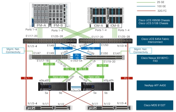
To build an IP only storage access in a FlexPod configuration, the components are set up as follows:
· Cisco UCS Fabric Interconnects provide chassis and network connectivity.
· The Cisco UCS X9508 Chassis connects to fabric interconnects using Cisco UCS X9108 Intelligent Fabric Module, where four 25 Gigabit Ethernet ports are used on each IFM to connect to the appropriate Fabric Interconnect. If additional bandwidth is required, all eight 25G ports can be utilized.
· Cisco UCS X210c M6 Compute Nodes contain fourth-generation Cisco 14425 virtual interface cards (VICs).
· Cisco UCS C220 or C240 Servers with fourth generation VICs 1457 VICs connect to the fabric interconnects with 25GE.
· Cisco Nexus 93180YC-FX3 Switches in Cisco NX-OS mode provide the switching fabric.
· Optional: Cisco MDS 9132T FC Switches provide the SAN switching fabric.
· Cisco UCS 6454 Fabric Interconnect 25-Gigabit Ethernet uplink ports connect to Cisco Nexus 93180YC-FX3 Switches in a Virtual Port Channel (vPC) configuration. Optional uplink connection to Cisco MDS 9132T FC Switches via Port Channel (PC) configuration.
· The NetApp AFF A400 controllers connect to the Cisco Nexus 93180YC-FX3 Switches using two 100 GE ports from each controller configured as a vPC. Optional connection to the Cisco MDS 9132T SAN Switches.
· SUSE software is installed on Cisco UCS Compute Nodes with local disks to validate the infrastructure.
Note: Since Cisco UCS C-series is being managed and configured by Cisco Intersight Managed Mode, the nodes must satisfy the software and hardware requirements outlined here: https://intersight.com/help/saas/supported_systems
VLAN Configuration
Table 1 lists VLANs configured for setting up the FlexPod environment along with their usage.
| VLAN ID |
Name |
Usage |
| Infrastructure related networks** |
||
| 2 |
Native-VLAN |
Use VLAN 2 as native VLAN instead of default VLAN (1) |
| 3072 |
OOB-MGMT-VLAN |
Out-of-band management VLAN to connect management ports for various devices |
| 17 |
IB-MGMT-VLAN |
In-band management VLAN utilized for all in-band management connectivity - for example, ESXi hosts, VM management, and so on. |
| 3117* |
iSCSI-A |
iSCSI-A path for data traffic |
| 3217* |
iSCSI-B |
iSCSI-B path for data traffic |
| VMware related networks** |
||
| 172 |
VM Traffic |
VM data traffic VLAN |
| 3017 |
NFS-VLAN |
NFS VLAN for Infrastructure components |
| 3317 |
vMotion |
VMware vMotion traffic |
| SUSE Rancher / RKE2 related networks |
||
| 1043 |
RKE2-Traffic1 |
Data traffic VLAN from/to RKE2 cluster 1 |
| 1047 |
RKE2-NFS1 |
NFS storage traffic VLAN for RKE2 cluster 1 |
| 2043 |
RKE2-Traffic2 |
Data traffic VLAN from/to RKE2 cluster 2 |
| 2047 |
RKE2-NFS2 |
NFS storage traffic VLAN for RKE2 cluster 2 |
* iSCSI is listed only for the VMware part.
**Infrastructure and VMware related VLANs are listed as reference as they are used to setup the infrastructure with this CVD: https://www.cisco.com/c/en/us/td/docs/unified_computing/ucs/UCS_CVDs/flexpod_ucs_xseries_e2e_ontap_manual_deploy.html
Some of the key highlights of VLAN usage are as follows:
· VLAN 3072 allows you to manage and access out-of-band management interfaces of various devices and is brought into the infrastructure to allow CIMC access to the UCS servers and is also available to infrastructure virtual machines (VMs). Interfaces in this VLAN are configured with MTU 1500.
· VLAN 17 is used for in-band management of VMs, hosts, and other infrastructure services. Interfaces in this VLAN are configured with MTU 1500.
· VLAN 3017 provides ESXi hosts, management systems, and other infrastructure services access to the NFS storage hosted on the NetApp Controllers. Interfaces in this VLAN are configured with MTU 9000.
◦ Optional: A pair of iSCSI VLANs (3117 and 3217) is configured to provide access to iSCSI based storage for data access. Interfaces in these VLANs are configured with MTU 9000.
· VLAN 1043 is used as an access network for RKE2 cluster 1 to access all RKE2 hosts, and services deployed on top. Interfaces in this VLAN are configured with MTU 1500.
· VLAN 1047 provides services deployed on top of RKE2 cluster 1 access to the NFS storage hosted on the NetApp Controllers managed by NetApp Astra Trident CSI. Interfaces in this VLAN are configured with MTU 9000.
· VLAN 2043 is used as an access network for RKE2 cluster 2 to access all RKE2 hosts, and services deployed on top. Interfaces in this VLAN are configured with MTU 1500.
· VLAN 2047 provides services deployed on top of RKE2 cluster 2 access to the NFS storage hosted on the NetApp Controllers managed by NetApp Astra Trident CSI. Interfaces in this VLAN are configured with MTU 9000.
Table 2 lists the hardware components used to build the solution in the lab. You are encouraged to review your requirements and adjust the various components as needed.
Table 2. FlexPod Hardware Components
| Component |
Hardware |
Comments |
| Cisco Nexus Switches |
Two Cisco Nexus 93180YC-FX3 switches |
|
| Cisco MDS Switches |
Two Cisco MDS 9132T switches |
Optional components. Only used for FC storage connection. |
| NetApp AFF Storage |
A NetApp AFF A400 HA Pair with appropriate storage and network connectivity. |
Your requirements will determine the amount of storage. The NetApp AFF A400 should support both 25Gbps (or 100 Gbps) ethernet and 32Gbps (or 16 Gbps) FC connectivity. |
| Cisco UCS Fabric Interconnects |
Two Cisco UCS 6454 Fabric Interconnects |
These fabric interconnects will be shared between the management and the workload domain. |
| Management Domain Compute |
||
| Cisco UCS Servers |
Two Cisco UCS nodes |
|
| Workload Domain Compute |
||
| Cisco UCS Chassis |
One UCS X9508 chassis. |
Single chassis can host up to 8 Cisco UCS X210c compute nodes. |
| Cisco UCS Compute Nodes |
Five Cisco UCS X210c compute nodes |
Two generations, M6 and M7, are validated. Two compute nodes are configured with X440p PCI node and GPU cards. |
Table 3 lists software versions of the components, drivers, and software (for example, various NetApp software tools, Cisco Intersight Assist, and so on) used to build this solution.
Table 3. Software Components and Versions
| Component |
Version |
| Cisco Nexus 93180YC-FX3 |
9.3(8) |
| Cisco UCS Fabric Interconnects |
4.3(2.230117) |
| Cisco UCS X-Series blade server |
5.0(2b) |
| Cisco UCS C-Series rack server |
4.3(2.240002) |
| Cisco Intersight Assist Appliance |
1.0.9-342 (will automatically upgrade to latest when claimed) |
| NetApp AFF A400 - ONTAP |
9.13.1 P6 |
| NetApp Astra Trident CSI |
24.02 |
| SUSE Rancher |
|
| SUSE Rancher Enterprise Container Manager |
2.8.2 |
| SUSE Linux Enterprise |
15 SP5 |
| SUSE Linux Enterprise Micro |
5.4 and 5.5 |
| K3s |
v1.26.9+k3s1 and v1.27.10+k3s1 |
| RKE |
V1.26.9.rke2r1 and v1.27.10+rke2r1 |
Table 4 lists the required components deployed as virtual machines to build the validated solution. You are encouraged to review the list and adjust the deployment type, the size or quantity of various components as needed.
Table 4. Virtual Machines were used for this solution
| Component |
Comments |
| vCenter Server |
Hosted on pre-existing infrastructure. |
| Intersight Assist |
Hosted on pre-existing infrastructure. Required to manage some on-premises components, like VMware or NetApp with Intersight. |
| Infrastructure and network services provides by a Linux System |
Hosted on pre-existing infrastructure. Used to provide required services for RKE2: DNS, DHCP, Load-Balancer, and NTP. |
| Management node |
Hosted on pre-existing infrastructure. Used to host the Ansible automation framework and to manage the solution. |
Ansible Automation for Solution Deployment
This section provides information about setting up and running Ansible playbooks to configure the infrastructure for the SUSE Rancher and RKE solution. As the focus of this solution validation was on the software and workload, the infrastructure setup is based on this document: https://www.cisco.com/c/en/us/td/docs/unified_computing/ucs/UCS_CVDs/flexpod_imm_m7_iac.html#AnsibleAutomationWorkflowandSolutionDeployment
For the deployment process, see: https://developer.cisco.com/codeexchange/github/repo/ucs-compute-solutions/FlexPod-IMM-VMware/. This document will guide you through the deployment process and highlight the additions required to make the SUSE Rancher and RKE software stack work. Ansible automation requires a management workstation (control machine) to run Ansible playbooks for configuring Cisco Nexus, NetApp ONTAP Storage, Cisco UCS, and SUSE Rancher/RKE.
A management workstation is a VM where Ansible is installed and has access to the Internet to download various packages and clone the playbook repository. Instructions for installing the workstation Operating System (OS) or complete setup of Ansible are not included in this document; however, basic installation and configuration of Ansible are provided as a reference. A guide for installing and getting started with Ansible can be found at: https://docs.ansible.com/ansible_community.html.
Procedure 1. Prepare Management Workstation
In this procedure, the installation steps are performed on a virtual machine running openSUSE Leap 15.5 to prepare the host for automated solution deployment. The automation includes the configuration of Cisco UCS, Cisco Nexus, NetApp Storage, and SUSE Rancher using Ansible Playbooks. The following steps were performed as root user.
Step 1. Install Python 3.11:
zypper install python311
update-alternatives --install /usr/bin/python3 python3 /usr/bin/python3.11 2
Step 2. Verify Python version:
python3 --version
Python 3.11.8
Step 3. Install Ansible:
pip3 install ansible
Step 4. Verify Ansible version:
ansible [core 2.16.5]
config file = None
configured module search path = ['/root/.ansible/plugins/modules', '/usr/share/ansible/plugins/modules']
ansible python module location = /usr/lib/python3.11/site-packages/ansible
ansible collection location = /root/.ansible/collections:/usr/share/ansible/collections
executable location = /usr/bin/ansible
python version = 3.11.8 (main, Feb 29 2024, 12:19:47) [GCC] (/usr/bin/python3.11)
jinja version = 3.1.3
libyaml = True
Step 5. Install git:
zypper install git-core
Step 6. Update pip and setup tools:
pip3 install --upgrade pip
pip3 install --upgrade setuptools
Step 7. Install NetApp specific modules:
pip3 install netapp-lib
Step 8. Install ansible-galaxy collections for Cisco UCS, NX-OS, NetApp, and VMware as follows:
ansible-galaxy collection install cisco.intersight
ansible-galaxy collection install cisco.nxos
pip3 install ansible-pylibssh
ansible-galaxy collection install netapp.ontap
ansible-galaxy collection install community.vmware
pip3 install -r ~/.ansible/collections/ansible_collections/community/vmware/requirements.txt
| Tech tip |
| In some instances, the following error messages might be seen when executing VMware specific ansible playbooks: An exception occurred during task execution. To see the full traceback, use -vvv. The error was: ModuleNotFoundError: No module named 'requests' fatal: [10.101.1.101 -> localhost]: FAILED! => {"changed": false, "msg": "Failed to import the required Python library (requests) on aa01-linux8.vm.vcf.local's Python /usr/bin/python3.11. Please read the module documentation and install it in the appropriate location. If the required library is installed, but Ansible is using the wrong Python interpreter, please consult the documentation on ansible_python_interpreter"}
An exception occurred during task execution. To see the full traceback, use -vvv. The error was: ModuleNotFoundError: No module named 'pyVim' fatal: [10.101.1.101 -> localhost]: FAILED! => {"changed": false, "msg": "Failed to import the required Python library (PyVmomi) on aa01-linux8.vm.vcf.local's Python /usr/bin/python3.11. Please read the module documentation and install it in the appropriate location. If the required library is installed, but Ansible is using the wrong Python interpreter, please consult the documentation on ansible_python_interpreter"} To fix this issue, use the appropriate version of PIP to install “requests” and “pyvmomi:” pip3 install requests pip3 install pyVmomi |
To download the Ansible playbooks for configuring the infrastructure, the management workstation needs a working installation of Git and access to the public GitHub repository. You can also manually download the repository and copy the files to the management workstation. The Ansible playbooks used in this document can be found at the following links:
Cisco DevNet: https://developer.cisco.com/codeexchange/github/repo/ucs-compute-solutions/FlexPod-IMM-VMware/
GitHub repository: https://github.com/ucs-compute-solutions/FlexPod-IMM-VMware
The Cisco Nexus Switches, NetApp Storage and Cisco UCS must be physically racked, cabled, powered, and configured with management IP addresses before the Ansible-based installation procedure can begin. Upgrade the Cisco UCS, Nexus Switches to appropriate software versions listed in Table 3.
Before executing the Ansible playbooks to setup various devices, several variables must be updated based on your specific implementation. These variables contain values such as the interfaces, interface numbering, VLANs, pools, policies and ports on Cisco UCS, IP addresses and interfaces for storage and so on.
Note: Day 2 Configuration tasks such as adding additional VLAN, datastores, Virtual Machines and so on, can be performed manually or with Cisco Intersight Cloud Orchestrator (ICO).
Procedure 1. Clone GitHub Collection
To copy the github repository for the project, clone the collection to a new (empty) folder on the management workstation. Cloning the repository creates a local copy, which is then used to modify and run the playbooks.
Step 1. From the management workstation, create a new folder for the project. The GitHub collection will be cloned to this new folder.
Step 2. Open a command-line or console interface on the management workstation and change directories to the newly created folder.
Step 3. Clone the GitHub collection using the following command:
cd <new folder>
git clone https://github.com/ucs-compute-solutions/FlexPod-IMM-VMware
This section provides the procedure for configuring the Cisco Nexus 93180YC-FX3 switches used for ethernet LAN switching in this solution. The switch configuration for this validated design is based on the switching configuration covered in FlexPod Datacenter with Cisco UCS X-Series Cisco Validated Design (CVD): https://www.cisco.com/c/en/us/td/docs/unified_computing/ucs/UCS_CVDs/flexpod_ucs_xseries_e2e_ontap_manual_deploy.html#NetworkSwitchConfiguration therefore this section only explains the changes from the base CVD.
Physical Connectivity
Follow the physical connectivity guidelines for FlexPod as explained in section FlexPod Topology.
Initial Configuration
For setting up the initial switch configuration, complete the steps explained here: https://www.cisco.com/c/en/us/td/docs/unified_computing/ucs/UCS_CVDs/flexpod_ucs_xseries_e2e_ontap_manual_deploy.html#InitialConfiguration
Manual Configuration Steps
The required configuration steps for the FlexPod solution are documented here:
https://www.cisco.com/c/en/us/td/docs/unified_computing/ucs/UCS_CVDs/flexpod_ucs_xseries_e2e_ontap_manual_deploy.html#CiscoNexusSwitchManualConfiguration.
Procedure 1. Create VLANs
Cisco Nexus A and Cisco Nexus B
In addition to the existing VLANs, follow this step on both switches. Refer to VLAN information in VLAN Configuration for setting up all the required VLANs.
Step 1. From the global configuration mode, run the following commands:
vlan <rke1-traffic-vlan-id e.g. 1043>
name rke1-traffic-vlan
vlan <rke1-nfs-vlan-id e.g. 1047>
name rke1-nfs-vlan
vlan <rke2-traffic-vlan-id e.g. 2043>
name rke2-traffic-vlan
vlan <rke2-nfs-vlan-id e.g. 2047>
name rke2-nfs-vlan
Procedure 2. Create Port Channel Parameters
Cisco Nexus A and Cisco Nexus B
To configure port channel parameters, follow the steps on both Cisco Nexus switches.
Step 1. From the global configuration mode, run the following commands to setup VPC Peer-Link port-channel:
interface Po10
switchport trunk allowed vlan add <rke1-traffic-vlan-id>,<rke1-nfs-vlan-id>,<rke2-traffic-vlan-id>,<rke2-nfs-vlan-id>
Step 2. From the global configuration mode, run the following commands to setup port-channels for UCS FI 6454 connectivity:
interface Po11
switchport trunk allowed vlan add <rke1-traffic-vlan-id>,<rke1-nfs-vlan-id>,<rke2-traffic-vlan-id>,<rke2-nfs-vlan-id>
spanning-tree port type edge trunk
!
interface Po12
switchport trunk allowed vlan add <rke1-traffic-vlan-id>,<rke1-nfs-vlan-id>,<rke2-traffic-vlan-id>,<rke2-nfs-vlan-id>
spanning-tree port type edge trunk
Step 3. From the global configuration mode, run the following commands to setup port-channels for NetApp A400 connectivity:
interface Po113
switchport trunk allowed vlan <ib-mgmt-vlan-id>, <infra-nfs-vlan-id>
switchport trunk allowed vlan add <rke1-nfs-vlan-id>,<rke2-nfs-vlan-id>
!
interface Po114
switchport trunk allowed vlan <ib-mgmt-vlan-id>, <infra-nfs-vlan-id>
switchport trunk allowed vlan add <rke1-nfs-vlan-id>,<rke2-nfs-vlan-id>
Step 4. From the global configuration mode, run the following commands to setup port-channels for connectivity to existing management switch:
interface Po17
switchport trunk allowed vlan <rke1-acccess-vlan-id>,<rke2-access-vlan-id>
interface PoXX
switchport trunk allowed vlan add <rke1-traffic-vlan-id>,<rke2-traffic-vlan-id>
!
exit
copy run start
Procedure 3. Configure IP Gateways
To enable internet access for the installation and the workloads we have enabled IP routing and HSRP function on the Nexus Switches. If IP gateways for the VLANs covered below are present on the upstream switches, the configuration in this step can be skipped. If some or all the gateways are not configured, use Hot Standby Router Protocol (HSRP) and Switched Virtual Interface (SVI) on the Nexus switches to set up gateways for Out-of-band management*, in-band management*, RKE2 access networks.
Note: *Gateways for management networks will be pre-configured in your existing environments.
Configure Nexus-A Switch
Step 1. From the global configuration mode, run the following commands to setup IP addresses and HSRP:
feature interface-vlan
feature hsrp
interface Vlan3072
description GW for Out-of-Band Mgmt 10.104.0.0/24 Network
no shutdown
no ip redirects
ip address 10.101.0.251/24
no ipv6 redirects
hsrp version 2
hsrp 1010
preempt delay minimum 300
priority 105
ip 10.104.0.254
interface Vlan17
description GW for In-band Management 10.104.1.0/24 Network
no shutdown
no ip redirects
ip address 10.104.1.251/24
no ipv6 redirects
hsrp version 2
hsrp 1011
preempt delay minimum 300
priority 105
ip 10.104.1.254
interface Vlan172
description GW for virtual machine 10.104.2.0/24 Network
no shutdown
! MTU should be adjusted based on application requirements
mtu 1500
no ip redirects
ip address 10.104.2.251/24
no ipv6 redirects
hsrp version 2
hsrp 1012
preempt delay minimum 300
priority 105
ip 10.104.2.254
interface Vlan1043
description Gateway for RKE1 Access VLAN
no shutdown
mtu 9216
no ip redirects
ip address 10.104.3.251/24
no ipv6 redirects
hsrp version 2
hsrp 3002
preempt delay minimum 300
priority 105
ip 10.104.3.254
interface Vlan2043
description Gateway for RKE2 Access VLAN
no shutdown
mtu 9216
no ip redirects
ip address 10.104.4.251/24
no ipv6 redirects
hsrp version 2
hsrp 3002
preempt delay minimum 300
priority 105
ip 10.104.4.254
Configure Nexus-B Switch
Step 1. From the global configuration mode, run the following commands to setup IP addresses and HSRP:
feature interface-vlan
feature hsrp
interface Vlan3072
description GW for Out-of-Band Mgmt 10.104.0.0/24 Network
no shutdown
no ip redirects
ip address 10.101.0.252/24
no ipv6 redirects
hsrp version 2
hsrp 1010
preempt delay minimum 300
ip 10.104.0.254
interface Vlan17
description GW for In-band Management 10.104.1.0/24 Network
no shutdown
no ip redirects
ip address 10.104.1.252/24
no ipv6 redirects
hsrp version 2
hsrp 1011
preempt delay minimum 300
ip 10.104.1.254
interface Vlan172
description GW for virtual machine 10.104.2.0/24 Network
no shutdown
! MTU should be adjusted based on application requirements
mtu 1500
no ip redirects
ip address 10.104.2.252/24
no ipv6 redirects
hsrp version 2
hsrp 1012
preempt delay minimum 300
ip 10.104.2.254
interface Vlan1043
description Gateway for RKE1 Access VLAN
no shutdown
mtu 9216
no ip redirects
ip address 10.104.3.252/24
no ipv6 redirects
hsrp version 2
hsrp 3002
preempt delay minimum 300
ip 10.104.3.254
interface Vlan2043
description Gateway for RKE2 Access VLAN
no shutdown
mtu 9216
no ip redirects
ip address 10.104.4.252/24
no ipv6 redirects
hsrp version 2
hsrp 3002
preempt delay minimum 300
ip 10.104.4.254
See the following section (NetApp Hardware Universe) for planning the physical location of the storage systems:
· Site Preparation
· System Connectivity Requirements
· Circuit Breaker, Power Outlet Balancing, System Cabinet Power Cord Plugs, and Console Pinout Requirements
· AFF Series Systems
To confirm that the hardware and software components that you would like to use are supported with the version of ONTAP that you plan to install, follow these steps at the NetApp Support site:
1. Access the HWU application to view the System Configuration guides.
2. Click the Products tab to select Platforms menu to view the compatibility between different versions of the ONTAP software and the NetApp storage appliances with your desired specifications.
3. Alternatively, to compare components by storage appliance, click Utilities and select compare Storage Systems.
Follow the physical installation procedures for the controllers found here: https://docs.netapp.com/us-en/ontap-systems/index.html.
NetApp storage systems support a wide variety of disk shelves and disk drives. The complete list of disk shelves that is supported by the AFF A400 is available at the NetApp Support site.
When using SAS disk shelves with NetApp storage controllers, refer to: https://docs.netapp.com/us-en/ontap-systems/sas3/install-new-system.html for proper cabling guidelines.
When using NVMe drive shelves with NetApp storage controllers, refer to: https://docs.netapp.com/us-en/ontap-systems/ns224/hot-add-shelf.html for installation and servicing guidelines.
Complete the NetApp AFF A400 initial cluster setup explained here: https://www.cisco.com/c/en/us/td/docs/unified_computing/ucs/UCS_CVDs/flexpod_imm_m7_iac.html#NetAppONTAPStorageConfiguration
FC, NVMe, iSCSI, and FC Boot have not been explained in the CVD since the current solution deployment contains Boot from Local Disk and implements NFS services to provide IP-based storage access for FlexPod. At the completion of this step, NetApp A400 management connectivity and ONTAP cluster setup is ready.
Procedure 1. Log into the Cluster
Step 1. Open an SSH connection to either the cluster IP or the host name.
Step 2. Log into the admin user with the password provided during cluster setup.
Procedure 2. Verify Storage Failover
To confirm that storage failover is enabled, run the following commands for a failover pair:
Step 1. Verify the status of the storage failover:
AA07-A400::> storage failover show
Takeover
Node Partner Possible State Description
-------------- -------------- -------- -------------------------------------
AA07-A400-01 AA07-A400-02 true Connected to AA07-A400-02
AA07-A400-02 AA07-A400-01 true Connected to AA07-A400-01
2 entries were displayed.
Note: Both <st-node01> and <st-node02> must be capable of performing a takeover. Continue with Step 2 if the nodes can perform a takeover.
Step 2. Enable failover on one of the two nodes if it was not completed during the installation:
storage failover modify -node <st-node01> -enabled true
Note: Enabling failover on one node enables it for both nodes.
Step 3. Verify the HA status for a two-node cluster.
Note: This step is not applicable for clusters with more than two nodes.
AA07-A400::> cluster ha show
High-Availability Configured: true
Step 4. If HA is not configured use the below commands. Only enable HA mode for two-node clusters.
Note: Do not run this command for clusters with more than two nodes because it causes problems with failover.
cluster ha modify -configured true
Do you want to continue? {y|n}: y
Step 5. Verify that hardware assist is correctly configured:
AA07-A400::> storage failover hwassist show
Node
-----------------
AA07-A400-01
Partner: AA07-A400-02
Hwassist Enabled: true
Hwassist IP: 192.x.x.84
Hwassist Port: 162
Monitor Status: active
Inactive Reason: -
Corrective Action: -
Keep-Alive Status: healthy
AA07-A400-02
Partner: AA07-A400-01
Hwassist Enabled: true
Hwassist IP: 192.x.x.85
Hwassist Port: 162
Monitor Status: active
Inactive Reason: -
Corrective Action: -
Keep-Alive Status: healthy
2 entries were displayed.
Procedure 3. Set Auto-Revert on Cluster Management Interface
To set the auto-revert parameter on the cluster management interface, follow this step:
Step 1. Run the following command:
network interface modify -vserver <clustername> -lif cluster_mgmt_lif_1 -auto-revert true
Note: A storage virtual machine (SVM) is referred to as a Vserver or vserver in the GUI and CLI.
Procedure 4. Zero All Spare Disks
Step 1. To zero all spare disks in the cluster, run the following command:
disk zerospares
Note: Advanced Data Partitioning creates a root partition and two data partitions on each SSD drive in an AFF configuration. Disk auto assign should have assigned one data partition to each node in an HA pair. If a different disk assignment is re-quired, disk auto assignment must be disabled on both nodes in the HA pair by running the disk option modify command. Spare partitions can then be moved from one node to another by running the disk removeowner and disk assign commands.
Procedure 5. Set Up Service Processor Network Interface
Step 1. Assign a static IPv4 address to the Service Processor on each node by running the following commands:
system service-processor network modify –node <st-node01> -address-family IPv4 –enable true –dhcp none –ip-address <node01-sp-ip> -netmask <node01-sp-mask> -gateway <node01-sp-gateway>
system service-processor network modify –node <st-node02> -address-family IPv4 –enable true –dhcp none –ip-address <node02-sp-ip> -netmask <node02-sp-mask> -gateway <node02-sp-gateway>
Note: The Service Processor IP addresses should be in the same subnet as the node management IP addresses.
Procedure 6. Create Manual Provisioned Aggregates
An aggregate containing the root volume is created during the ONTAP setup process. To manually create additional aggregates, determine the aggregate name, the node on which to create it, and the number of disks it should contain.
Step 1. To create new aggregates, run the following commands:
storage aggregate create -aggregate <aggr1_node01> -node <st-node01> -diskcount <num-disks> -diskclass solid-state
storage aggregate create -aggregate <aggr1_node02> -node <st-node02> -diskcount <num-disks> -diskclass solid-state
Note: You should have the minimum number of hot spare disks for the recommended hot spare disk partitions for their aggregate.
Note: For all-flash aggregates, you should have a minimum of one hot spare disk or disk partition. For non-flash homogenous aggregates, you should have a minimum of two hot spare disks or disk partitions. For Flash Pool aggregates, you should have a minimum of two hot spare disks or disk partitions for each disk type.
Note: In an AFF configuration with a small number of SSDs, you might want to create an aggregate with all, but one remaining disk (spare) assigned to the controller.
Note: The aggregate cannot be created until disk zeroing completes. Run the storage aggregate show command to display the aggregate creation status. Do not proceed until both aggr1_node01 and aggr1_node02 are online.
Procedure 7. Remove Default Broadcast Domains
By default, all network ports are included in separate default broadcast domain. Network ports used for data services (for example e0e, e0f, and so on) should be removed from their default broadcast domain and that broadcast domain should be deleted.
Step 1. To perform this task, run the following commands:
network port broadcast-domain delete -broadcast-domain <Default-N> -ipspace Default
network port broadcast-domain show
Note: Delete the Default broadcast domains with Network ports.
Procedure 8. Disable Flow Control on 25/100GbE Data Ports
To disable flow control on 25 and 100GbE data ports, follow these steps:
Step 1. Run the following command to configure the ports on node 01:
network port modify -node <st-node01> -port e0e,e0f,e0g,e0h -flowcontrol-admin none
Step 2. Run the following command to configure the ports on node 02:
network port modify -node <st-node02> -port e0e,e0f,e0g,e0h -flowcontrol-admin none
Step 3. Run the following command to verify:
network port show -node * -port e0e,e0f,e0g,e0h -fields speed-admin,duplex-admin,flowcontrol-admin
Procedure 9. Enable Cisco Discovery Protocol
Step 1. To enable the Cisco Discovery Protocol (CDP) on the NetApp storage controllers, run the following command to enable CDP in ONTAP:
node run -node * options cdpd.enable on
Procedure 10. Enable Link-layer Discovery Protocol on all Ethernet Ports
Step 1. Enable Link-layer Discovery Protocol (LLDP) on all ports of all nodes in the cluster:
node run * options lldp.enable on
Procedure 11. Enable FIPS Mode on the NetApp ONTAP Cluster (Optional)
NetApp ONTAP is compliant in the Federal Information Processing Standards (FIPS) 140-2 for all SSL connections. When SSL FIPS mode is enabled, SSL communication from NetApp ONTAP to external client or server components outside of NetApp ONTAP will use FIPS compliant crypto for SSL.
Step 1. To enable FIPS on the NetApp ONTAP cluster, run the following commands:
set -privilege advanced
security config modify -interface SSL -is-fips-enabled true
Note: If you are running NetApp ONTAP 9.8 or earlier manually reboot each node in the cluster one by one. Beginning in NetApp ONTAP 9.9.1, rebooting is not required.
Note: If FIPS is not enabled on the NetApp ONTAP cluster, you will see a warning in AIQUM stating “FIPS Mode Disabled.”
Procedure 12. Configure Timezone
To configure time synchronization on the cluster, follow this step:
Step 1. Set the time zone for the cluster.
timezone -timezone <timezone>
Note: For example, in the eastern United States, the time zone is America/New_York
Procedure 13. Configure Simple Network Management Protocol
Note: If you have enabled FIPS then please look at the following points while configuring SNMP.
· The SNMP users or SNMP traphosts that are non-compliant with FIPS will be deleted automatically. “Configure SNMP traphosts” configuration will be non-compliant with FIPS.
· The SNMPv1 user, SNMPv2c user (After configuring SNMP community) or SNMPv3 user (with none or MD5 as authentication protocol or none or DES as encryption protocol or both) is non-compliant with FIPS.
Step 1. Configure basic SNMP information, such as the location and contact. When polled, this information is visible as the sysLocation and sysContact variables in SNMP.
snmp contact <snmp-contact>
snmp location “<snmp-location>”
snmp init 1
options snmp.enable on
Step 2. Configure SNMP traps to send to remote hosts, such as an Active IQ Unified Manager server or another fault management system.
Note: This step works when FIPS is disabled.
Note: An SNMPv1 traphost or SNMPv3 traphost (configured with an SNMPv3 user non-compliant to FIPS) is non-compliant to FIPS.
snmp traphost add <oncommand-um-server-fqdn>
Step 3. Configure SNMP community.
Note: This step works when FIPS is disabled.
Note: SNMPv1 and SNMPv2c are not supported when cluster FIPS mode is enabled.
system snmp community add -type ro -community-name <snmp-community> -vserver <clustername>
Procedure 14. Configure SNMPv3 Access
SNMPv3 offers advanced security by using encryption and passphrases. The SNMPv3 user can run SNMP utilities from the traphost using the authentication and privacy settings that you specify.
Note: When FIPS is enabled, the following are the supported/compliant options for authentication and privacy protocol:
· Authentication Protocol: sha, sha2-256
· Privacy protocol: aes128
Step 1. To configure SNMPv3 access, run the following commands:
security login create -user-or-group-name <<snmp-v3-usr>> -application snmp -authentication-method usm
Enter the authoritative entity's EngineID [local EngineID]:
Which authentication protocol do you want to choose (none, md5, sha, sha2-256) [none]: <<snmp-v3-auth-proto>>
Enter the authentication protocol password (minimum 8 characters long):
Enter the authentication protocol password again:
Which privacy protocol do you want to choose (none, des, aes128) [none]: <<snmpv3-priv-proto>>
Enter privacy protocol password (minimum 8 characters long):
Enter privacy protocol password again:
Note: Refer to the SNMP Configuration Express Guide for additional information when configuring SNMPv3 security users.
Procedure 15. Remove insecure ciphers from the NetApp ONTAP Cluster
Note: If you do not perform this procedure, you will see the warning in AIQUM “SSH is using insecure ciphers.”
Step 1. Ciphers with the suffix CBC are considered insecure. To remove the CBC ciphers, run the following NetApp ONTAP command:
security ssh remove -vserver <clustername> -ciphers aes256-cbc,aes192-cbc,aes128-cbc,3des-cbc
Procedure 16. Create Management Broadcast Domain
Step 1. If the management interfaces are required to be on a separate VLAN, create a new broadcast domain for those interfaces by running the following command:
network port broadcast-domain create -broadcast-domain IB-MGMT -mtu 1500
Procedure 17. Create NFS Broadcast Domain
Step 1. To create an NFS data broadcast domain with a maximum transmission unit (MTU) of 9000, run the following commands to create a broadcast domain for NFS in ONTAP:
network port broadcast-domain create -broadcast-domain Infra-NFS -mtu 9000
Procedure 18. Create 2 Default Broadcast Domains and Add ifgroups a0a interface on each node to Default Broadcast Domain (applicable for 2-node cluster only)
Step 1. Create default broadcast domain.
broadcast-domain create -broadcast-domain Default-1 -mtu 9000 -ipspace Default
broadcast-domain create -broadcast-domain Default-2 -mtu 9000 -ipspace Default
Step 2. To add ports to default broadcast domains, run the following commands:
AA07-A400::> broadcast-domain add-ports -broadcast-domain Default-1 -ports AA07-A400-01:a0a
(network port broadcast-domain add-ports)
AA07-A400::> broadcast-domain add-ports -broadcast-domain Default-2 -ports AA07-A400-02:a0a
(network port broadcast-domain add-ports)
Procedure 19. Create Interface Groups
Step 1. To create the LACP interface groups for the 25GbE data interfaces, run the following commands:
network port ifgrp create -node <st-node01> -ifgrp a0a -distr-func port -mode multimode_lacp
network port ifgrp add-port -node <st-node01> -ifgrp a0a -port e0e
network port ifgrp add-port -node <st-node01> -ifgrp a0a -port e0f
network port ifgrp add-port -node <st-node01> -ifgrp a0a -port e0g
network port ifgrp add-port -node <st-node01> -ifgrp a0a -port e0h
network port ifgrp create -node <st-node02> -ifgrp a0a -distr-func port -mode multimode_lacp
network port ifgrp add-port -node <st-node02> -ifgrp a0a -port e0e
network port ifgrp add-port -node <st-node02> -ifgrp a0a -port e0f
network port ifgrp add-port -node <st-node02> -ifgrp a0a -port e0g
network port ifgrp add-port -node <st-node02> -ifgrp a0a -port e0h
####To Verify: ####
AA07-A400::> network port ifgrp show
Port Distribution Active
Node IfGrp Function MAC Address Ports Ports
-------- ---------- ------------ ----------------- ------- -------------------
AA07-A400-01
a0a port d2:39:ea:29:d4:4a full e0e, e0f, e0g, e0h
AA07-A400-02
a0a port d2:39:ea:29:ce:d5 full e0e, e0f, e0g, e0h
2 entries were displayed.
Procedure 20. Create VLANs
Step 1. Create the management VLAN ports and add them to the management broadcast domain:
network port vlan create –node <st-node01> -vlan-name a0a-<ib-mgmt-vlan-id>
network port vlan create –node <st-node02> -vlan-name a0a-<ib-mgmt-vlan-id>
network port broadcast-domain add-ports -broadcast-domain IB-MGMT -ports <st-node01>:a0a-<ib-mgmt-vlan-id>,<st-node02>:a0a-<ib-mgmt-vlan-id>
Step 2. To verify, issue the following command:
network port vlan show
Step 3. Create the NFS VLAN ports and add them to the Infra-NFS broadcast domain:
network port vlan create –node <st-node01> -vlan-name a0a-<infra-nfs-vlan-id>
network port vlan create –node <st-node02> -vlan-name a0a-<infra-nfs-vlan-id>
network port broadcast-domain add-ports -broadcast-domain Infra-NFS -ports <st-node01>:a0a-<infra-nfs-vlan-id>,<st-node02>:a0a-<infra-nfs-vlan-id>
Procedure 21. Create SVM (Storage Virtual Machine)
The SVM (AA04-RKE2-BM-SVM) is used to configure NFS services for storage access by NetApp Astra Trident.
Step 1. Run the vserver create command:
vserver create –vserver AA04-RKE2-BM-SVM
Step 2. Add the required data protocols to the SVM:
vserver add-protocols -protocols nfs -vserver AA04-RKE2-BM-SVM
Step 3. Remove the unused data protocols from the SVM:
vserver remove-protocols –vserver AA04-RKE2-BM-SVM -protocols cifs,fcp,iscsi
Note: It is recommended to remove fcp and iscsi protocols if they are not used:
Step 4. Add the two data aggregates to the AA04-RKE2-BM-SVM aggregate list for the NetApp ONTAP Tools:
vserver modify –vserver AA04-RKE2-BM-SVM –aggr-list < AA07_A400_01_NVME_SSD_1>,< AA07_A400_02_NVME_SSD_1>
Step 5. Enable and run the NFS protocol in the AA04-RKE2-BM-SVM:
vserver nfs create -vserver AA04-RKE2-BM-SVM -udp disabled -v3 enabled -v4.1 enabled -vstorage enabled
Note: If the NFS license was not installed during the cluster configuration, make sure to install the license before starting the NFS service.
Procedure 22. Vserver Protocol Verification
Step 1. Verify the required protocols are added to the AA04-RKE2-BM-SVM vserver:
AA07-A400::> vserver show-protocols -vserver AA04-RKE2-BM-SVM
Vserver: AA04-RKE2-BM-SVM
Protocols: nfs
Procedure 23. Create Load-Sharing Mirrors of SVM Root Volume
Step 1. Create a load-sharing mirror volume of the “AA04-RKE2-BM-SVM” SVM root volume on the node that does not have the Root Volume:
volume show -vserver AA04-RKE2-BM-SVM # Note down the aggregate and node for the root volume
volume create –volume AA04_RKE2_SVM_BM_root_lsm0<x> –aggregate <AA07_A400_0x_NVME_SSD_1> –size 1GB –type DP
Step 2. Create a job schedule to update the root volume mirror relationships every 15 minutes:
job schedule interval create -name 15min -minutes 15
Step 3. Create mirroring relationships:
snapmirror create –source-path AA04-RKE2-BM-SVM:AA04_RKE_SVM_root -destination-path AA04-RKE2-BM-SVM: AA04_RKE2_SVM_BM_root_lsm0<x> –type LS -schedule 15min
Step 4. Initialize the mirroring relationship:
AA07-A400::> snapmirror initialize-ls-set -source-path AA04-RKE2-BM-SVM:AA04_RKE2_BM_SVM_root
[Job 19735] Job is queued: snapmirror initialize-ls-set for source "AA07-A400://AA04-RKE2-BM-SVM/AA04_RKE2_BM_SVM_root".
To verify:
AA07-A400::> snapmirror show -vserver AA04-RKE2-BM-SVM
Progressss
Source Destination Mirror Relationship Total Last
Path Type Path State Status Progress Healthy Updated
----------- ---- ------------ ------- -------------- --------- ------- --------
AA07-A400://AA04-RKE2-BM-SVM/AA04_RKE2_BM_SVM_root
LS AA07-A400://AA04-RKE2-BM-SVM/AA04_RKE2_BM_SVM_root_lsm01
Snapmirrored
Idle - true -snapmirror show -type ls
Procedure 24. Configure HTTPS Access
To configure secure access to the storage controller, follow these steps:
Step 1. Increase the privilege level to access the certificate commands:
set -privilege diag
Do you want to continue? {y|n}: y
Step 2. A self-signed certificate is already in place. Verify the certificate and obtain parameters (for example, the <serial-number>) by running the following command:
security certificate show
Step 3. For each SVM shown, the certificate common name should match the DNS fully qualified domain name (FQDN) of the SVM. Delete the two default certificates and replace them with either self-signed certificates or certificates from a certificate authority (CA). To delete the default certificates, run the following commands:
security certificate delete -vserver AA04-RKE2-BM-SVM -common-name AA04-RKE2-BM-SVM -ca AA04-RKE2-BM-SVM -type server -serial <serial-number>
Note: Deleting expired certificates before creating new certificates is best practice. Run the security certificate delete command to delete the expired certificates. In the following command, use TAB completion to select and delete each default certificate.
Step 4. To generate and install self-signed certificates, run the following commands as one-time commands. Generate a server certificate for the AA04-RKE2-BM-SVM and the cluster SVM. Use TAB completion to aid in the completion of these commands.
security certificate create -common-name <cert-common-name> -type server -size 2048 -country <cert-country> -state <cert-state> -locality <cert-locality> -organization <cert-org> -unit <cert-unit> -email-addr <cert-email> -expire-days <cert-days> -protocol SSL -hash-function SHA256 -vserver AA04-RKE2-BM-SVM
Step 5. To obtain the values for the parameters required in step 5 (<cert-ca> and <cert-serial>), run the security certificate show command.
Step 6. Enable each certificate that was just created by using the –server-enabled true and –client-enabled false parameters. Use TAB completion to aid in the completion of these commands.
security ssl modify -vserver <clustername> -server-enabled true -client-enabled false -ca <cert-ca> -serial <cert-serial> -common-name <cert-common-name>
Step 7. Disable HTTP cluster management access.
network interface service-policy remove-service -vserver <clustername> -policy default-management -service management-http
Note: It is normal for some of these commands to return an error message stating that the entry does not exist.
Step 8. Change back to the normal admin privilege level and verify that the system logs are available in a web browser.
set –privilege admin
https://<node01-mgmt-ip>/spi
https://<node02-mgmt-ip>/spi
Procedure 25. Set password for SVM vsadmin user and unlock the user
Step 1. Set a password for the SVM vsadmin user and unlock the user using the following commands:
security login password –username vsadmin –vserver AA04-RKE2-BM-SVM
Enter a new password: <password>
Enter it again: <password>
security login unlock –username vsadmin –vserver AA04-RKE2-BM-SVM
Procedure 26. Configure login banner for the SVM
Step 1. To create login banner for the SVM, run the following command:
security login banner modify -vserver AA04-RKE2-BM-SVM -message "This AA04-RKE2-BM-SVM is reserved for authorized users only!"
Note: If the login banner for the SVM is not configured, users will observe a warning in AIQUM stating “Login Banner Disabled.”
Procedure 27. Remove insecure ciphers from the SVM
Ciphers with the suffix CBC are considered insecure.
Note: If you do not perform the procedure, you will see a warning in AIQUM saying “SSH is using insecure ciphers.”
Step 1. To remove the CBC ciphers from the SVM, run the following NetApp ONTAP command:
security ssh remove -vserver AA04-RKE2-BM-SVM -ciphers aes256-cbc,aes192-cbc,aes128-cbc,3des-cbc
Procedure 28. Configure Export Policy Rule
Note: This step is crucial when using ontap-nas (NFS) storage driver in Astra Trident since this SVM is added as a Trident Backend.
To configure NFS on the SVM, follow these steps:
Step 1. Create a new rule for the infrastructure NFS subnet in the default export policy:
vserver export-policy rule create –vserver AA04-RKE2-BM-SVM -policyname default –ruleindex 1 –protocol nfs -clientmatch <infra-nfs-subnet-cidr> -rorule any –rwrule any -superuser sys –allow-suid true -anon 65534
Note: For more information on configuring NFS Export Policy for Trident, go to: https://docs.netapp.com/us-en/trident/trident-use/ontap-nas-prep.html#requirements.
Step 2. Assign the FlexPod export policy to the infrastructure SVM (AA04-RKE2-BM-SVM) root volume:
volume modify –vserver AA04-RKE2-BM-SVM –volume AA04_RKE2_BM_SVM_root –policy default
Procedure 29. Create FlexVol Volumes
The following information is required to create a NetApp FlexVol® volume:
· The volume name
· The volume size
· The aggregate on which the volume exists
Step 1. Run the following command to create a volume for storing SVM audit log configuration:
volume create -vserver AA04-RKE2-BM-SVM -volume audit_log -aggregate <aggr1_node01> -size 50GB -state online -
policy default -junction-path /audit_log -space-guarantee none -percent-snapshot-space 0
Step 2. Update set of load-sharing mirrors using the command below:
snapmirror update-ls-set -source-path AA04-RKE2-BM-SVM:AA04_RKE2_SVM_BM_root
Procedure 30. Create NFS LIFs
Step 1. To create NFS LIFs, run the following commands:
network interface create -vserver AA04-RKE2-BM-SVM -lif nfs-lif-01 -service-policy default-data-files -home-node <st-node01> -home-port a0a-<rke1-nfs-vlan-id> –address <node01-nfs-lif-01-ip> -netmask <node01-nfs-lif-01-mask> -status-admin up –failover-policy broadcast-domain-wide –auto-revert true
network interface create -vserver AA04-RKE2-BM-SVM -lif nfs-lif-02 -service-policy default-data-files -home-node <st-node02> -home-port a0a-<rke1-nfs-vlan-id> –address <node02-nfs-lif-02-ip> -netmask <node02-nfs-lif-02-mask>> -status-admin up –failover-policy broadcast-domain-wide –auto-revert true
Step 2. To verify, run the following commands:
AA07-A400::> network interface show -vserver AA04-RKE2-BM-SVM -service-policy default-data-files
Logical Status Network Current Current Is
Vserver Interface Admin/Oper Address/Mask Node Port Home
----------- ---------- ---------- ------------------ ------------- ------- ----
AA04-RKE2-BM-SVM
nfs-lif-01 up/up 10.104.7.1/24 AA07-A400-01 a0a-1047 true
nfs-lif-02 up/up 10.104.7.2/24 AA07-A400-02 a0a-1047 true
2 entries were displayed.
Procedure 31. Create SVM Management LIF (Add Infrastructure SVM Administrator)
To add the SVM administrator and SVM administration LIF in the in-band management network, follow these steps:
Step 1. Run the following commands:
network interface create –vserver AA04-RKE2-BM-SVM –lif svm-mgmt –home-node <st-node02> -home-port a0a-<ib-mgmt-vlan-id> –address <svm-mgmt-ip> -netmask <svm-mgmt-mask> -status-admin up -auto-revert true -service-policy default-management –failover-policy broadcast-domain-wide
Step 2. Create a default route that enables the SVM management interface to reach the outside world.
network route create –vserver AA04-RKE2-BM-SVM -destination 0.0.0.0/0 –gateway <svm-mgmt-gateway>
Step 3. To verify, run the following commands:
AA07-A400::> network route show -vserver AA04-RKE2-BM-SVM
Vserver Destination Gateway Metric
------------------- --------------- --------------- ------
AA04-RKE2-BM-SVM
0.0.0.0/0 10.104.0.254 10
Step 4. Add route to reach the corresponding RKE2 master/worker network:
AA07-A400::> net route show -vserver AA04-RKE2-BM-SVM
(network route show)
Vserver Destination Gateway Metric
------------------- --------------- --------------- ------
AA04-RKE2-BM-SVM
0.0.0.0/0 10.104.0.254 10
10.104.3.0/24 10.104.3.254 20
10.104.7.0/24 10.104.7.254 20
3 entries were displayed.
Note: A cluster serves data through at least one and possibly several SVMs. With these steps, you’ve created a single data SVM. You can create additional SVMs depending on your requirement.
Procedure 32. Configure Auto Support
NetApp AutoSupport® sends support summary information to NetApp through HTTPS.
Step 1. To configure AutoSupport, run the following command:
system node autosupport modify -state enable –mail-hosts <mailhost> -from <from-address> -transport https -support enable -to <storage-admin-email>
Procedure 33. Configure DNS for Infrastructure SVM (AA04-RKE2-BM-SVM)
Step 1. To configure DNS for the Infra-SVM, run the following command:
dns create -vserver <vserver-name> -domains <dns-domain> -nameserve <dns-servers>
Example:
dns create -vserver AA04-RKE2-BM-SVM -domains aa04.cspgb4.local -nameservers 10.104.1.4,10.104.1.6
Procedure 34. Create and enable auditing configuration for the SVM
Note: If you do not perform this procedure for the SVM, you will see a warning in AIQUM stating “Audit Log is disabled.”
Step 1. To create auditing configuration for the SVM, run the following command:
vserver audit create -vserver AA04-RKE2-BM-SVM -destination /audit_log
Step 2. Run the following command to enable audit logging for the SVM:
vserver audit enable -vserver AA04-RKE2-BM-SVM
Note: It is recommended that you enable audit logging so you can capture and manage important support and availability information. Before you can enable auditing on the SVM, the SVM’s auditing configuration must already exist.
Procedure 35. Test Auto Support
Step 1. To test the Auto Support configuration by sending a message from all nodes of the cluster, run the following command:
autosupport invoke -node * -type all -message “FlexPod ONTAP storage configuration for RKE2 is completed”
Now the setup of the NetApp storage is completed. Since SLES servers are booted with local disks, storage configuration for boot is not required. The configuration required for NetApp Astra Trident will be done later.
Cisco Intersight Managed Mode – Initial Setup
This chapter contains the following:
· Set up Cisco Intersight Managed Mode on Cisco UCS Fabric Interconnects
· Set up Cisco Intersight Account
· Initial Cisco Intersight Configuration
The Cisco Intersight Managed Mode (also referred to as Cisco IMM or Intersight Managed Mode) is a new architecture that manages Cisco Unified Computing System™ (Cisco UCS®) fabric interconnect–attached systems. Cisco Intersight managed mode standardizes both policy and operation management for Cisco UCS B-series M5 and M6 servers, Cisco UCS X210c M6 and M7 compute nodes used in this deployment guide. For a complete list of supported platforms, go to: https://www.cisco.com/c/en/us/td/docs/unified_computing/Intersight/b_Intersight_Managed_Mode_Configuration_Guide/b_intersight_managed_mode_guide_chapter_01010.html
During the initial setup, Cisco UCS FIs are configured in Intersight Managed Mode and added to a newly created Intersight account. Intersight organization creation, resource group definition and license setup are also part of the initial setup. At the end of this section, you can start creating various chassis and server level policies and profiles to deploy Cisco UCS compute nodes.
Set up Cisco Intersight Managed Mode on Cisco UCS Fabric Interconnects
To set up Cisco UCS 6454 Fabric Interconnects in Intersight Managed Mode, complete the steps explained here: https://www.cisco.com/c/en/us/td/docs/unified_computing/ucs/UCS_CVDs/flexpod_ucs_xseries_e2e_ontap_manual_deploy.html#CiscoIntersightManagedModeSetUp
Note: If a software version that supports Intersight Managed Mode (4.1(3) or later) is already installed on Cisco UCS Fabric Interconnects, do not upgrade the software to a recommended recent release using Cisco UCS Manager. The software upgrade will be performed using Cisco Intersight to make sure Cisco UCS X-series firmware is part of the software upgrade.
Set up Cisco Intersight Account
To set up a new Cisco Intersight Account, complete the steps explained here: https://www.intersight.com/help/saas/getting_started/create_cisco_intersight_account
Note: Setting up a new Intersight account is not necessary if you plan to add the Cisco UCS FIs to an existing account.
Initial Cisco Intersight Configuration
When setting up a new Cisco Intersight account (as described in this document), the account needs to be enabled for Cisco Smart Software Licensing. It is also required to configure Organizations, Resource Groups, and to claim the Cisco UCS hardware.
Cisco Intersight Managed Mode – Domain Profile Setup
This chapter contains the following:
· Review and Deploy the Domain Profile
· Configure Cisco UCS Chassis Profile (optional)
A Cisco UCS domain profile configures a fabric interconnect pair through reusable policies, allows configuration of the ports and port channels, and configures the VLANs and VSANs in the network. It defines the characteristics of and configured ports on fabric interconnects. The domain-related policies can be attached to the profile either at the time of creation or later. One Cisco UCS domain profile can be assigned to one fabric interconnect domain.
Domain profile setup has the following steps:
· General configuration – name and organization assignment
· UCS Domain Assignment – assign previously claimed UCS Fabric Interconnects to the domain profile
· VLAN configuration – define required VLANs
· Port configuration – configure server and uplink ports and port-channels for Ethernet traffic
· UCS domain configuration – policies such as NTP, DNS and QoS
· Review and deploy – review the configuration and deploy the UCS domain profile
To configure the name, description, and organization for the UCS domain profile, complete the steps from Procedure 9 and following, explained here: https://www.cisco.com/c/en/us/td/docs/unified_computing/ucs/UCS_CVDs/flexpod_ucs_xseries_e2e_ontap_manual_deploy.html#CiscoIntersightManagedModeSetUp
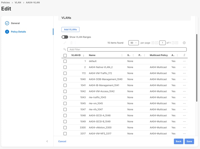
To define the VLANs, complete the steps explained here:
https://www.cisco.com/c/en/us/td/docs/unified_computing/ucs/UCS_CVDs/flexpod_ucs_xseries_e2e_ontap_manual_deploy.html#VLANandVSANConfiguration before continuing with the RKE2 specific configurations.
Figure 2. UCS Domain Profile VLAN Policy Mapping
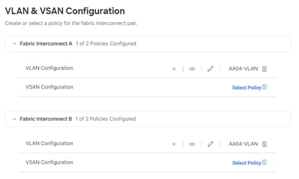
Procedure 1. Add SUSE Rancher/RKE2 VLANs to the Domain Profile
To add the RKE2 VLANs to the Domain Profile, follow the steps shown in the screenshot below:
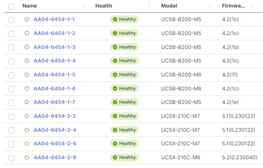
Review and Deploy the Domain Profile
With a successful deployment of the UCS domain profile, the ethernet port channels should be enabled and the Cisco UCS rack servers and compute nodes should be successfully discovered.
Figure 3. Example of discovered compute nodes and rack server
Configure Cisco UCS Chassis Profile (optional)
Cisco UCS Chassis profile in Cisco Intersight allows you to configure various parameters for the chassis, including:
· IMC Access Policy: IP configuration for the in-band chassis connectivity. This setting is independent of Server IP connectivity and only applies to communication to and from chassis.
· SNMP Policy, and SNMP trap settings.
· Power Policy to enable power management and power supply redundancy mode.
· Thermal Policy to control the speed of FANs.
A chassis policy can be assigned to any number of chassis profiles to provide a configuration baseline for a chassis. In this deployment, no chassis profile was created or attached but you can configure policies to configure SNMP or Power parameters and attach them to the chassis as needed. For more information about configuring UCS chassis policies, go to: https://www.cisco.com/c/en/us/td/docs/unified_computing/ucs/UCS_CVDs/flexpod_ucs_xseries_e2e_ontap_manual_deploy.html#CiscoIntersightManagedModeSetUp
Cisco Intersight Managed Mode – Server Profile Template
This chapter contains the following:
· vNIC Placement for Server Profile Templates
· Server Profile Template Creation
In Cisco Intersight Managed Mode, a server profile enables resource management by simplifying policy alignment and server configuration. The server profiles are derived from a server profile template. Server profile template and its associated policies can be created using the server profile template wizard.
If VMware ESXi hosts will be deployed on the same UCS Domain, complete the steps explained here: https://www.cisco.com/c/en/us/td/docs/unified_computing/ucs/UCS_CVDs/flexpod_ucs_xseries_e2e_ontap_manual_deploy.html#CiscoUCSIMMManualConfiguration
In this document, one server profile template is created for SUSE Rancher and RKE2 hosts deployed bare metal.
vNIC Placement for Server Profile Templates
This section explains the vNIC definitions and placement for server profile templates.
SUSE RKE2 Host vNIC Placement
Two vNICs are configured and manually placed as listed in Table 5.
Table 5. vNIC placement for Management Domain hosts
| vNIC/vHBA Name |
Slot |
Switch ID |
PCI Order |
| rke-access |
MLOM |
A |
0 |
| rke-storage |
MLOM |
B |
1 |
Server Profile Template Creation
Procedure 1. Configure a Server Profile Template
Step 1. Log in to Cisco Intersight.
Step 2. Go to Infrastructure Service > Configure > Templates and in the main window click Create UCS Server Profile Template.
Procedure 2. General Configuration
Step 1. Select the organization from the drop-down list (for example RTP4-AA04).
Step 2. Provide a name for the server profile template. The name used in this deployment is AA04-RKE-Local
Step 3. Select UCS Server (FI-Attached).
Step 4. Provide an optional description.
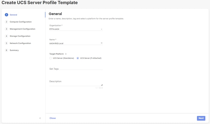
Step 5. Click Next.
Procedure 3. Compute Configuration – UUID Pool
Follow these steps to configure UUID pool under the Compute Configuration.
Note: For additional granularity, you can choose to create different UUID pools for different workloads or departments.
Step 1. Click Select Pool under UUID Pool and then in the pane on the right, click Create New.
Step 2. Verify correct organization is selected from the drop-down list (for example RTP4-AA04) and provide a name for the UUID Pool (for example, AA04-UUID-Pool).
Step 3. Provide an optional Description and click Next.
Step 4. Provide a UUID Prefix (for example, a random prefix of AA040000-0000-0001 was used).
Step 5. Add a UUID block.
Step 6. Click Create.
Procedure 4. Compute Configuration – BIOS policy
Follow these steps to configure BIOS policies under the Compute Configuration.
Step 1. Click Select Policy next to BIOS and in the pane on the right, click Create New.
Step 2. Verify correct organization is selected from the drop-down list (for example, RTP4-AA04) and provide a name for the policy (for example, AA04-RKE-BIOS or AA04-RKE-BIOS-M6).
Step 3. Click Next.
Step 4. On the Policy Details screen, select appropriate values for the BIOS settings. In this deployment, the default BIOS values were selected.
Step 5. Click Create.
Procedure 5. Compute Configuration - Boot Order policy for Management Domain hosts
Follow these steps to configure Boot Order policy for RKE2 hosts booting from local disk.
Step 1. Click Select Policy next to Boot Order and then, in the pane on the right, click Create New.
Step 2. Verify correct organization is selected from the drop-down list (for example, RTP4-AA04) and provide a name for the policy (for example, AAO4-RKE-Local-Boot).
Step 3. Click Next.
Step 4. For Configured Boot Mode option, select Unified Extensible Firmware Interface (UEFI).
Step 5. Turn on Enable Secure Boot.
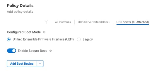
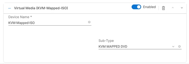
Step 6. Click Add Boot Device drop-down list and select Virtual Media.
Step 7. Provide a device name (for example, KVM-Mapped-ISO) and then, for the subtype, select KVM Mapped DVD.
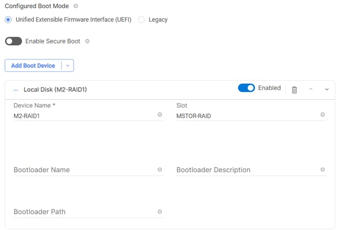
Step 8. From the Add Boot Device drop-down list, select Local Disk.
Step 9. Provide the Device Name: M2-RAID1 and the Slot: MSTOR-RAID.
Step 10. Verify the order of the boot policies and adjust the boot order as necessary using arrows next to the delete button.
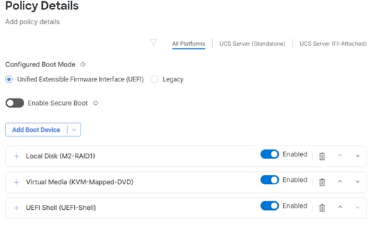
Step 11. Click Create.
Procedure 6. Compute Configuration - Virtual Media Policy
Follow these steps to configure Virtual Media Policy to allow mapping an ISO files as installation source for operating system.
Step 1. Click Select Policy next to Virtual Media and then, in the pane on the right, click Create New.
Step 2. Verify correct organization is selected from the drop-down list (for example, RTP4-AA04) and provide a name for the policy (for example, AA04-SLE-15).
Step 3. Turn on Enable Virtual Media, Enable Virtual Media Encryption, and Enable Low Power USB.
Step 4. Do not Add Virtual Media at this time.
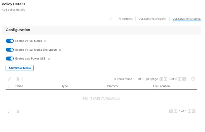
Step 5. Click Create.
Step 6. Click Next to move to Management Configuration.
Management Configuration
These policies will be added to the management configuration:
· IMC Access to define the pool of IP addresses for compute node KVM access.
· IPMI Over LAN to allow Intersight to manage IPMI messages.
· Local User to provide local administrator to access KVM.
· Virtual KVM to allow the Tunneled KVM.
Procedure 1. Management Configuration - Cisco IMC access policy
Follow these steps to configure Cisco IMC access policy:
Step 1. Click Select Policy next to IMC Access and then, in the pane on the right, click Create New.
Step 2. Verify correct organization is selected from the drop-down list (for example, RTP4-AA04) and provide a name for the policy (for example, AA04-IMC-Access).
Step 3. Click Next.
Note: You can select in-band management access to the compute node using an in-band management VLAN (for example, VLAN 17) or out-of-band management access via the Mgmt0 interfaces of the FIs. Policies like SNMP, vMedia and Syslog are currently not supported via Out-Of-Band and will require an In-Band IP to be configured. In-band management access was configured in this deployment guide.
Step 4. Enable In-Band Configuration and provide the in-band management VLAN (for example, 17).
Step 5. Make sure IPv4 address configuration is selected.
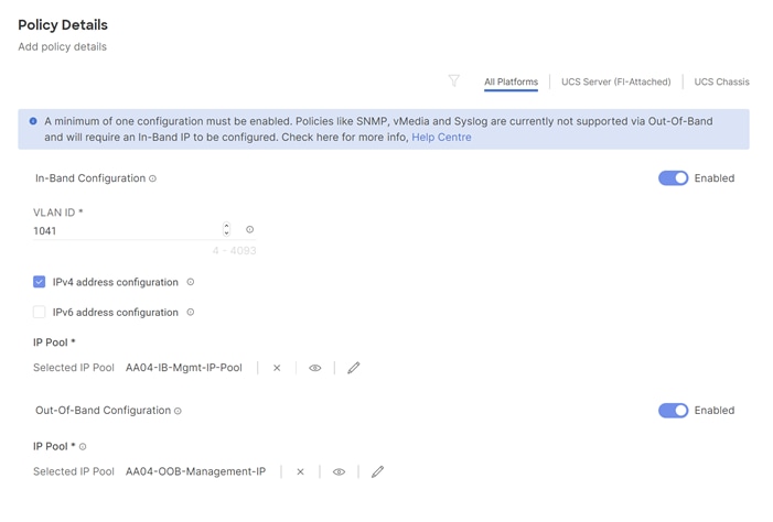
Step 6. Under IP Pool, click Select IP Pool and then, in the pane on the right, click Create New.
Step 7. Verify correct organization is selected from the drop-down list (for example, RTP4-AA04) and provide a name for the pool (for example, AA04-Mgmt-IP-Pool).
Step 8. Select Configure IPv4 Pool and provide the information to define a pool for KVM IP address assignment including an IP Block.
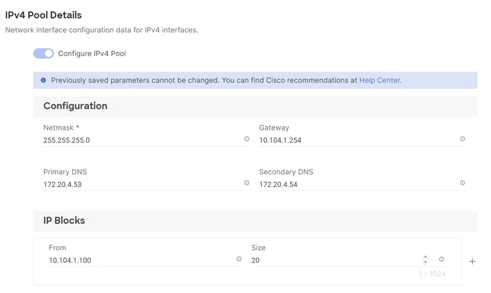
Note: The management IP pool subnet should be accessible from the host that is trying to access the KVM session. In the example shown here, the hosts trying to establish a KVM connection would need to be able to route to 10.101.1.0/24 subnet.
Step 9. Click Next.
Step 10. Unselect Configure IPv6 Pool.
Step 11. Click Create to finish configuring the IP address pool.
Step 12. Click Create to finish configuring the IMC access policy.
Procedure 2. Management Configuration - IPMI Over LAN policy
Follow these steps to configure IPMI Over LAN policy.
Step 1. Click Select Policy next to IPMI Over LAN and then, in the pane on the right, click Create New.
Step 2. Verify the correct organization is selected from the drop-down list (for example, RTP4-AA04) and provide a name for the policy (for example, AA04-IPMIoverLAN-Policy).
Step 3. Turn on Enable IPMI Over LAN.
Step 4. Click Create.
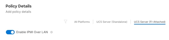
Procedure 3. Management Configuration - Local User policy
Follow these steps to configure local user policy:
Step 1. Click Select Policy next to Local User and then, in the pane on the right, click Create New.
Step 2. Verify correct organization is selected from the drop-down list (for example, RTP4-AA04) and provide a name for the policy (for example, AA04-VM-IPMI-Pol).
Step 3. Verify that UCS Server (FI-Attached) is selected.
Step 4. Verify that Enforce Strong Password is selected.
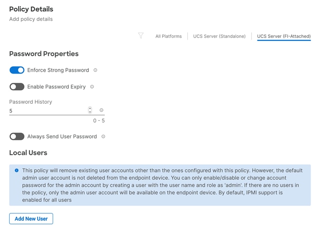
Step 5. Click Add New User and then click + next to the New User.
Step 6. Provide the username (for example, fpadmin), choose a role (for example, admin), and provide a password.
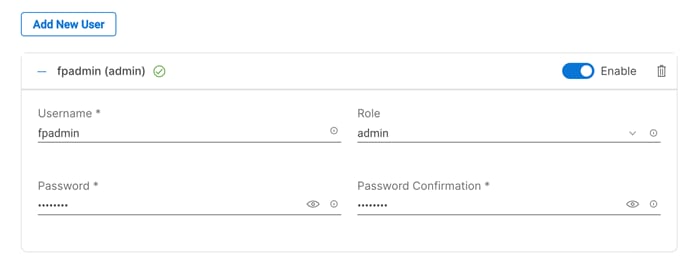
Note: The username and password combination defined here can be used to log into KVMs as well as for IPMI access.
Step 7. Click Create to finish configuring the user.
Step 8. Click Create to finish configuring the local user policy.
Step 9. Click Next to move to Storage Configuration.
Procedure 4. Management Configuration - Virtual KVM Policy
Follow these steps to configure the KVM policy:
Step 1. Click Select Policy next to Virtual KVM and then, in the pane on the right, click Create New.
Step 2. Verify correct organization is selected from the drop-down list (for example, RTP4-AA04 and provide a name for the policy (for example, AA04-VM-KVM).
Step 3. Verify that UCS Server (FI-Attached) is selected.
Step 4. Turn on Allow Tunneled vKVM and leave the other two options on as well.
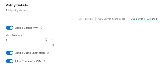
Step 5. Click Create.
Note: To fully enable Tunneled KVM, make sure under System > Settings > Security and Privacy>Configure, “Allow Tunneled vKVM Launch” and “Allow Tunneled vKVM Configuration” is turned on.
Step 6. Click Next to move to Storage Configuration.
Storage Configuration
Storage configuration covers the local disk configuration options. In this configuration two M.2 SSD devices connected to a M.2 RAID controller were used.
Procedure 1. Storage Configuration – Storage
Follow these steps to configure Storage Policy to configure a RAID1 on the two M.2 SSD devices for the operating system.
Step 1. Click Select Policy next to Storage and then, in the pane on the right, click Create New.
Step 2. Verify correct organization is selected from the drop-down list (for example, RTP4-AA04) and provide a name for the policy (for example, MStor-Boot), click Next.
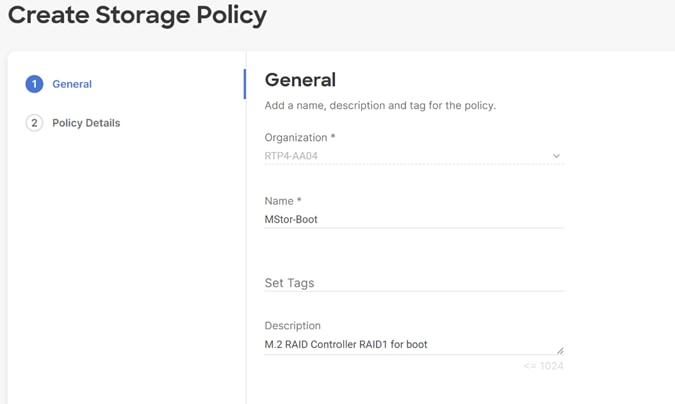
Step 3. Enable Use JBOD drives for virtual drive creation, enable M.2 RAID Configuration, and select MSTOR-RAID1, MSTOR-RAID2 from the drop-down list, click Create.
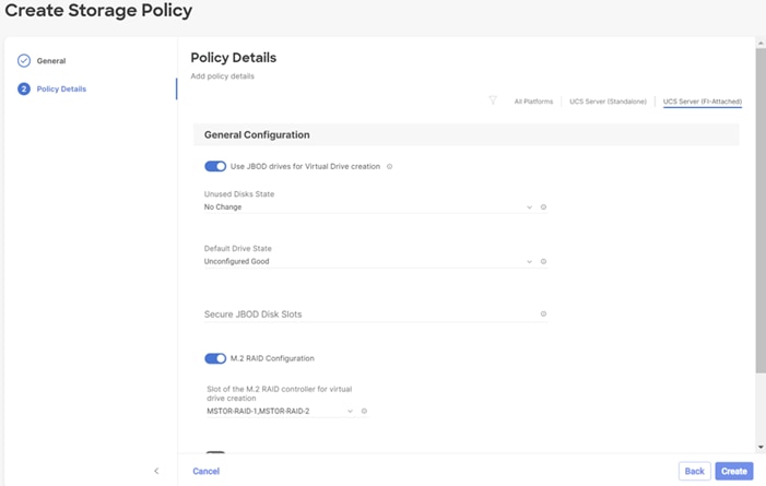
Step 4. Back in the storage configuration window, click Next.
Network Configuration
Network configuration encompasses both LAN and SAN connectivity policies.
Network Configuration - LAN Connectivity
LAN connectivity policy defines the connections and network communication resources between the server and the LAN. This policy uses pools to assign MAC addresses to servers and to identify the vNICs that the servers use to communicate with the network. For consistent vNIC and vHBA placement, manual vHBA/vNIC placement is utilized.
The RKE2 hosts use two vNICs configured as shown in Table 6.
Table 6. vNICs for setting up LAN Connectivity Policy
| vNIC/vHBA Name |
Slot |
Switch ID |
PCI Order |
| rke-access |
MLOM |
A |
0 |
| rke-storage |
MLOM |
B |
1 |
Procedure 1. Create LAN Connectivity Policy
Step 1. Click Select Policy next to LAN Connectivity and then, in the pane on the right, click Create New.
Step 2. Verify correct organization is selected from the drop-down list (for example, RTP4-AA04) and provide a name for the policy (for example, AA04-RKE-LanCon-Pol). Click Next.
Step 3. Under vNIC Configuration, select Manual vNICs Placement.
Step 4. Click Add vNIC.
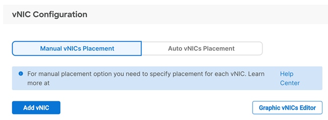
Network Configuration - LAN Connectivity - MAC Pool
If the MAC address pool has not been defined yet, you will need to create a new MAC address pool when creating the first vNIC.
Note: For better segmentation two separate MAC address pools can be used, like AA04-Mac-Pool-A for all Fabric-A vNICs and AA04-Mac-Pool-B for all Fabric-B vNICs.
Table 7. MAC Address Pools
| Pool Name |
Starting MAC Address |
Size |
vNICs |
| AA04-Mac-Pool-A |
00:25:B5:A4:0A:00 |
256* |
rke-access, rke-vm-traffic |
| AA04-Mac-Pool-B |
00:25:B5:A4:0B:00 |
256* |
rke-storage |
Note: Each server requires 2 MAC addresses from the pool. Adjust the size of the pool according to your requirements. “A4” in the MAC address pool above is a unique identifier representing the rack ID. Adding a unique identifier helps with troubleshooting of switching issues.
Procedure 1. Define the MAC Pool
Step 1. Click Select Pool under MAC Address Pool and then, in the pane on the right, click Create New.
Step 2. Verify correct organization is selected from the drop-down list (for example, RTP4-AA04) and provide a name for the pool from Table 7.
Step 3. Click Next.
Step 4. Provide the starting MAC address from Table 7 (for example, 00:25:B5:A4:0B:00)
Step 5. Provide the size of the MAC address pool from Table 7 (for example, 255).
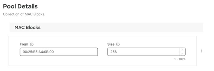
Step 6. Click Create to finish creating the MAC address pool.
Step 7. From the Add vNIC window, provide a vNIC Name, Slot ID, Switch ID, and PCI Order information from Table 6.
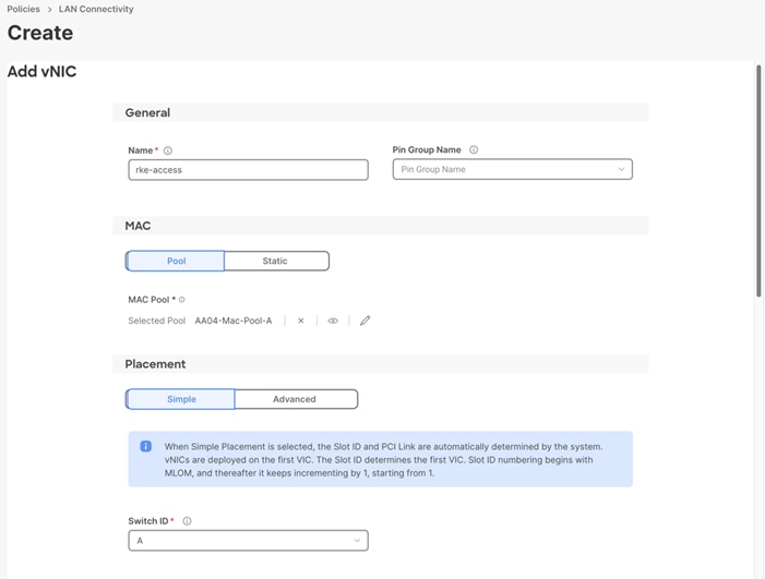
Step 8. For Consistent Device Naming (CDN), from the drop-down list, select vNIC Name.
Step 9. Verify that Failover is enabled.
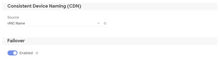
Network Configuration - LAN Connectivity– Ethernet Network Group Policy
Ethernet Network Group policies will be created and reused on applicable vNICs as explained below. Ethernet network group policy defines the VLANs allowed for a particular vNIC therefore multiple network group policies will be defined as listed in Table 8.
Table 8. Ethernet Group Policy Values
| Group Policy Name |
Native VLAN |
Apply to vNICs |
VLANs |
| AA04-RKE1-Access |
rke1-access-VLAN (1043) |
rke-access |
rke1-access-VLAN (1043) |
| AA04-RKE1-Storage |
rke1-storage-VLAN (1047) |
rke-storage |
rke1-storage-VLAN (1047) |
Note: *Adding an Out-of-Band Management VLAN is optional and depends on your requirements.
Procedure 1. Define Ethernet Group Policy for a vNIC
Step 1. Click Select Policy under Ethernet Network Group Policy and then, in the pane on the right, click Create New.
Step 2. Verify the correct organization is selected from the drop-down list (for example, RTP4-AA04) and provide a name for the policy from the Table 8 (for example, AA04-RKE-Access).
Step 3. Click Next.
Step 4. Enter the Allowed VLANs and Native VLAN from the Table 8.
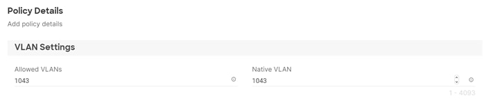
Step 5. Click Create to finish configuring the Ethernet network group policy.
Note: When ethernet group policies are shared between two vNICs, the ethernet group policy only needs to be defined for the first vNIC. For subsequent vNIC policy mapping, click Select Policy and pick the previously defined ethernet group policy from the list.
Network Configuration - LAN Connectivity– Ethernet Network Control Policy
Ethernet Network Control Policy is used to enable Cisco Discovery Protocol (CDP) and Link Layer Discovery Protocol (LLDP) for the vNICs. A single policy will be created here and reused for all the vNICs.
Procedure 1. Create the Ethernet Network Control Policy
Step 1. Click Select Policy under Ethernet Network Control Policy and in the pane on the right, click Create New.
Step 2. Verify correct organization is selected from the drop-down list (for example, RTP4-AA04) and provide a name for the policy (for example, AA04-VM-NetControl-Policy).
Step 3. Click Next.
Step 4. Enable Cisco Discovery Protocol and both Enable Transmit and Enable Receive under LLDP.
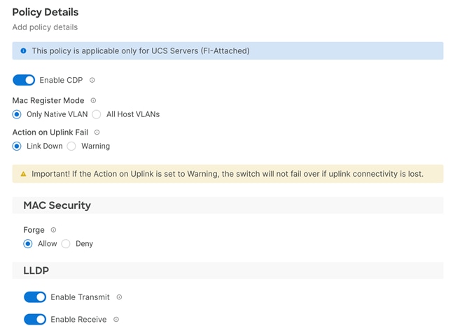
Step 5. Click Create to finish creating Ethernet network control policy.
Network Configuration - LAN Connectivity - Ethernet QoS
Ethernet QoS policy is used to enable jumbo maximum transmission units (MTUs) for the vNICs. A single policy will be created and reused for all the vNICs.
Procedure 1. Create the Ethernet QoS
Step 1. Click Select Policy under Ethernet QoS and in the pane on the right, click Create New.
Step 2. Verify correct organization is selected from the drop-down list (for example, RTP4-AA04) and provide a name for the policy (for example, AA04-QoS-9000).
Step 3. Click Next.
Step 4. Change the MTU, Bytes value to 9000.
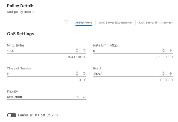
Step 5. Click Create to finish setting up the Ethernet QoS policy.
Network Configuration - LAN Connectivity - Ethernet Adapter
The Ethernet adapter policy is used to set the interrupts and the send and receive queues. The values are set according to the best-practices guidance for the operating system in use. Cisco Intersight provides default Ethernet Adapter policy for typical Linux deployments.
You can also configure a tweaked ethernet adapter policy for additional hardware receive queues handled by multiple CPUs in scenarios where there is a lot of storage traffic and multiple flows. In this deployment, an unmodified ethernet adapter policy is created and attached to the interfaces.
Procedure 1. Create the Ethernet Adapter
Step 1. Click Select Policy under Ethernet Adapter and then, in the pane on the right, click Create New.
Step 2. Verify correct organization is selected from the drop-down list (for example, RTP4-AA04) and provide a name for the policy (for example, AA04-Linux-Adapter-Policy).
Step 3. Click Select Default Configuration under Ethernet Adapter Default Configuration.
![]()
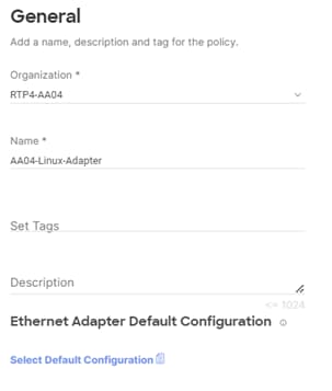
Step 4. From the list, select Linux.
Step 5. Click Next.
Step 6. For the AA04-Linux-Adapter Policy, click Create and skip the rest of the steps in this “Create Ethernet Adapter Policy” section.
Step 7. Click Add to add the vNIC to the LAN connectivity policy.
Step 8. Go to Step 7 Add vNIC and repeat vNIC creation for all vNICs.
Step 9. Verify all four vNICs were successfully created for appropriate LAN connectivity Policy.
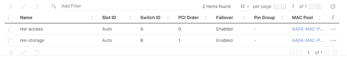
Step 10. Click Create to finish creating the LAN Connectivity policy.
Step 11. Back in the network configuration window, click Next and click Close.
Procedure 1. Derive the number of server profiles for the planned deployment from the configured template
Step 1. From the Infrastructure Services > Configure > Templates, click “…” next to the host template name and select Derive Profiles.
Step 2. Under the Server Assignment, select Assign Now and pick the number of servers required to create the K3s or RKE2 cluster. You can adjust the number of servers depending on the number of profiles to be deployed.
Note: For Non-Production systems a single node K3s cluster is okay to use. For production systems it is recommended to use at the minimum a three node RKE2 cluster for high availability.
Figure 4. Derive Server Profiles for three RKE2 nodes
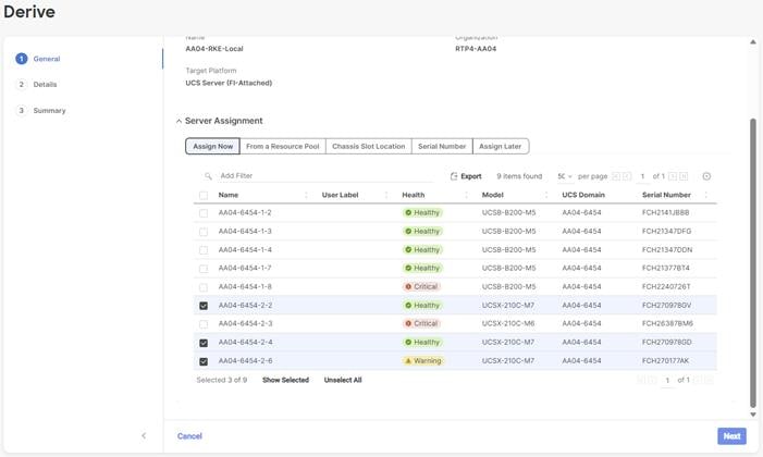
Step 3. Click Next.
Step 4. Intersight will fill in “default” information for the selected servers (only two out of four servers shown below):
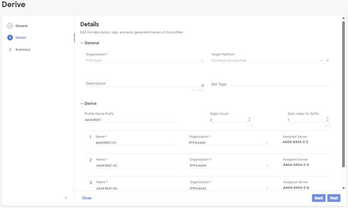
Step 5. Adjust the Prefix name and number (if needed).
Step 6. Click Next.
Step 7. Verify the information and click Derive to create the Server Profiles.
Step 8. Intersight will start configuring the server profiles and will take some time to apply all the policies. Use the Requests tab to see the progress.
![]()
Step 9. When the Server Profiles are deployed successfully, they will appear under the Server Profiles with the status of OK:
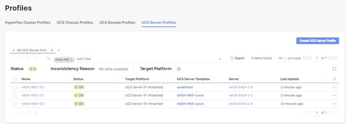
This chapter contains the following:
· Deploy and Configure Network Services
· SUSE Linux Enterprise Installation on all Nodes
· Deployment Option with SUSE SLE Micro and K3s
· Deploy and Configure NetApp Astra Trident
· NetApp Astra Trident Deployment
To deploy the required services, like DNS, we used a management node to deploy and configure them. This is to highlight the required or recommended configuration on one example. Please use your existing systems to configure the requirements accordantly.
Note: Before continuing the SUSE Rancher deployment, review the prerequisites: https://ranchermanager.docs.rancher.com/pages-for-subheaders/installation-requirements
| Software |
Version |
| SUSE Rancher |
2.8.2 |
| SUSE Linux Enterprise |
15 SP5 |
| SUSE Linux Enterprise Micro |
5.4 |
| K3s |
v1.27.10+k3s1 |
| Rancher Kubernetes Engine (RKE) |
v1.27.10+rke2r1 |
| NetApp Astra Trident |
24.02 |
The following are the prerequisites for SUSE Rancher Enterprise Container Manager:
· Configure DHCP or set static IP addresses on each node.
· DNS is an absolute MUST. Without proper DNS configuration, the installation will not continue.
· Ensure network connectivity among nodes, DNS, DHCP (if used), HAProxy, Installer or Management node.
Note: Using the DHCP server to manage the machines for the cluster long-term is recommended. Ensure that the DHCP server is configured to provide persistent IP addresses and host names to the cluster machines.
Note: In the deployment, DHCP server is setup for installing Rancher and RKE2 master and worker nodes.
Minimum Required Machines
The smallest RKE2 cluster require the following hosts:
· 3 x hosts to run control plane, etcd, and worker function.
Deploy and Configure Network Services
For detailed information about the installation options, please refer to SUSE Rancher documentation.
A SUSE Rancher on RKE2 installation involves the following high-level steps:
1. Prepare SUSE Linux and RKE2 installation.
2. Install and configure SUSE operating system.
3. Install and configure RKE2 cluster.
4. Install and configure SUSE Rancher.
5. Validate the installation.
1. To provide the deployment of the required services – DNS, Load balancer, DHCP, and https – a single SUSE Linux system was used in this document. Please use your existing services and add the required information or use the documentation from SUSE to make the services high available for production landscapes.
Procedure 1. Install the Required Software Components
Follow these steps to install the required software components on the system hosting the services – we named it sle-svc.
Step 1. Take care that the system is registered with SUSE to get the latest versions, and add the required package modules:
# suseconnect --email uk*****n@cisco.com --regcode 36************C3
Registering system to SUSE Customer Center
Using E-Mail:uk*****n@cisco.com
Announcing system to https://scc.suse.com ...
Activating SLES 15.4 x86_64 ...
-> Adding service to system ...
Activating sle-module-basesystem 15.4 x86_64 ...
-> Adding service to system ...
-> Installing release package ...
Activating sle-module-server-applications 15.4 x86_64 ...
-> Adding service to system ...
-> Installing release package ...
Successfully registered system
#
Step 2. Install the DNS and DHCP server components:
# zypper install -t pattern dhcp_dns_server
…
The following 6 recommended packages were automatically selected:
bind-doc dhcp dhcp-relay dhcp-tools yast2-dhcp-server yast2-dns-server
The following 12 NEW packages are going to be installed:
bind bind-doc dhcp dhcp-relay dhcp-server dhcp-tools libmariadb3 patterns-base-basesystem patterns-server-dhcp_dns_server
yast2-dhcp-server yast2-dns-server yast2-sysconfig
The following 2 NEW patterns are going to be installed:
basesystem dhcp_dns_server
12 new packages to install.
Overall download size: 3.7 MiB. Already cached: 0 B. After the operation, additional 14.4 MiB will be used.
Continue? [y/n/v/...? shows all options] (y): y
…
#
Step 3. Install the http server:
# zypper install apache2
…
The following 7 NEW packages are going to be installed:
apache2 apache2-prefork apache2-utils libapr-util1 libapr1 libbrotlienc1 system-user-wwwrun
7 new packages to install.
Overall download size: 2.2 MiB. Already cached: 0 B. After the operation, additional 6.2 MiB will be used.
Continue? [y/n/v/...? shows all options] (y): y
…
#
Step 4. Install the haproxy software:
# zypper addrepo https://download.opensuse.org/repositories/server:http/15.5/server:http.repo
Adding repository 'Webservers and tools around it (15.5)' ................................................[done]Repository 'Webservers and tools around it (15.5)' successfully added
URI : https://download.opensuse.org/repositories/server:/http/15.5/
Enabled : Yes
GPG Check : Yes
Autorefresh : No
Priority : 99 (default priority)
Repository priorities are without effect. All enabled repositories share the same priority.
#
# zypper refresh
Repository 'SLE-Module-Basesystem15-SP5-Pool' is up to date.
Repository 'SLE-Module-Basesystem15-SP5-Updates' is up to date.
Repository 'SLE-Module-Python3-15-SP5-Pool' is up to date.
Repository 'SLE-Module-Python3-15-SP5-Updates' is up to date.
Repository 'SLE-Product-SLES15-SP5-Pool' is up to date.
Repository 'SLE-Product-SLES15-SP5-Updates' is up to date.
Repository 'SLE-Module-Server-Applications15-SP5-Pool' is up to date.
Repository 'SLE-Module-Server-Applications15-SP5-Updates' is up to date.
New repository or package signing key received:
Repository: Webservers and tools around it (15.5)
Key Fingerprint: F9F2 2DA4 3BD1 5B00 05E5 5C53 B268 0E8E 08D1 D8B3
Key Name: server:http OBS Project
Key Algorithm: DSA 1024
Key Created: Mon Jul 17 12:43:37 2023
Key Expires: Wed Sep 24 12:43:37 2025
Rpm Name: gpg-pubkey-08d1d8b3-64b56fb9
Note: Signing data enables the recipient to verify that no modifications occurred after the data
were signed. Accepting data with no, wrong or unknown signature can lead to a corrupted system
and in extreme cases even to a system compromise.
Note: A GPG pubkey is clearly identified by its fingerprint. Do not rely on the key's name. If
you are not sure whether the presented key is authentic, ask the repository provider or check
their web site. Many providers maintain a web page showing the fingerprints of the GPG keys they
are using.
Do you want to reject the key, trust temporarily, or trust always? [r/t/a/?] (r): a
Retrieving repository 'Webservers and tools around it (15.5)' metadata ..............................................................[done]
Building repository 'Webservers and tools around it (15.5)' cache ...................................................................[done]
All repositories have been refreshed.
sle-svc:~ #
sle-svc:~ # zypper install haproxy
Refreshing service 'Basesystem_Module_15_SP5_x86_64'.
Refreshing service 'Containers_Module_15_SP5_x86_64'.
Refreshing service 'Python_3_Module_15_SP5_x86_64'.
Refreshing service 'SUSE_Linux_Enterprise_Server_15_SP5_x86_64'.
Refreshing service 'SUSE_Package_Hub_15_SP5_x86_64'.
Refreshing service 'Server_Applications_Module_15_SP5_x86_64'.
Loading repository data...
Reading installed packages...
Resolving package dependencies...
The following NEW package is going to be installed:
haproxy
The following package has no support information from its vendor:
haproxy
1 new package to install.
Overall download size: 2.6 MiB. Already cached: 0 B. After the operation, additional 7.6 MiB will be used.
Continue? [y/n/v/...? shows all options] (y): y
Retrieving: haproxy-2.8.3+git0.86e043add-lp155.1.1.x86_64 (Webservers and tools around it (15.5))
(1/1), 2.6 MiB
Retrieving: haproxy-2.8.3+git0.86e043add-lp155.1.1.x86_64.rpm ..............................[done (296.9 KiB/s)]
/
Checking for file conflicts: .............................................................................[done]
/usr/sbin/useradd -r -c User for haproxy -d /var/lib/haproxy -U haproxy -s /usr/sbin/nologin s
(1/1) Installing: haproxy-2.8.3+git0.86e043add-lp155.1.1.x86_64 ..........................................[done]
#
Set up DNS
DNS is used for name resolution and reverse name resolution. DNS A/AAAA or CNAME records are used for name resolution and PTR records are used for reverse name resolution. The reverse records are important because SUSE Rancher and RKE2 uses FQDN to create self signed certificates. Additionally, the reverse records are used to generate the certificate signing requests (CSR) for official certificates.
Note: In this design, we setup the DNS server (named) on the management node by executing zypper in -t pattern dhcp_dns_server to install the required software components
The following DNS records are required for an RKE2 cluster that hosts Rancher ECM. A complete DNS record takes the form: <component>.<cluster_name>.<base_domain>.
Table 10. Required DNS records
| Component |
DNS A/AAA Record |
IP Address |
Description |
| Kubernetes API |
api.rke1.aa04.cspgb4.local |
10.104.3.3 |
IP address for the Load balancer for the control plane machines. These records must be resolvable by both clients external to the cluster and from all the nodes within the cluster. The API server must be able to resolve the worker nodes by the host names that are recorded in Kubernetes. If the API server cannot resolve the node names, then proxied API calls can fail, and you cannot retrieve logs from pods. |
| rancher.rke1.aa04.cspgb4.local |
10.104.3.3 |
||
| Control hosts |
rke1-01.rke1.aa04.cspgb4.local |
10.104.3.31 |
Control nodes or Control + worker nodes |
| rke1-02.rke1.aa04.cspgb4.local |
10.104.3.32 |
||
| rke1-03.rke1.aa04.cspgb4.local |
10.104.3.33 |
||
| Worker hosts |
rke1-04.rke1.aa04.cspgb4.local |
10.104.3.34 |
Worker nodes |
| rke1-05.rke1.aa04.cspgb4.local |
10.104.3.35 |
||
| …… |
………. |
||
| rke1-XX.rke1.aa04.cspgb4.local |
10.104.3.NN |
Step 5. For high availability, it is required to configure the host entry for the Rancher deployment to the ip address of the load balancer. In this installation the load balancer is running on the management node:
# cat /var/lib/named/named.rke1
$TTL 3H
@ IN SOA rke1.aa04.cspgb4.local. root.rke1.aa04.cspgb4.local. (
2023091600 ; serial
1h ; refresh
15 ; retry
1d ; expire
1h ; minimum
)
@ IN NS dns.rke1.aa04.spgb4.local.
sle-svc IN A 10.104.3.4
dns IN CNAME sle-svc.aa04.cspgb4.local.
lb IN CNAME sle-svc.aa04.cspgb4.local.
rancher IN CNAME sle-svc.aa04.cspgb4.local.
apps IN A 10.104.3.49
api IN A 10.104.3.30
rke1-01 IN A 10.104.3.31
rke1-02 IN A 10.104.3.32
rke1-03 IN A 10.104.3.33
rke1-04 IN A 10.104.3.34
rke1-05 IN A 10.104.3.35
rke1-06 IN A 10.104.3.36
rke1-07 IN A 10.104.3.37
rke1-08 IN A 10.104.3.38
rke1-09 IN A 10.104.3.39
;
#
# cat /var/named/named.10.104.3
$TTL 3H
@ IN SOA aa04.cspgb4.local. root.aa04.cspgb4.local. (
2023091600 ; serial
1h ; refresh
15 ; retry
1d ; expire
1h ; minimum
)
@ IN NS dns.rke1.aa04.cspgb4.local.
3 IN PTR sle-mgmt01.rke1.aa04.cspgb4.local.
30 IN PTR api.rke1.aa04.cspgb4.local.
31 IN PTR rke1-01.rke1.aa04.cspgb4.local.
32 IN PTR rke1-02.rke1.aa04.cspgb4.local.
33 IN PTR rke1-03.rke1.aa04.cspgb4.local.
34 IN PTR rke1-04.rke1.aa04.cspgb4.local.
35 IN PTR rke1-05.rke1.aa04.cspgb4.local.
36 IN PTR rke1-06.rke1.aa04.cspgb4.local.
37 IN PTR rke1-07.rke1.aa04.cspgb4.local.
38 IN PTR rke1-08.rke1.aa04.cspgb4.local.
39 IN PTR rke1-09.rke1.aa04.cspgb4.local.
#
A webserver is used in the setup to make the agent ISO-Image available via the vMedia policy to the UCS servers. The webserver must be reached by UCS over the OOB-Management and IB-Management network during the installation.
Note: In this design, we set up the Apache web server (httpd) on the management node.
Note: If you are setting up webserver and HAProxy in management node for serving installation files, and iso, make sure it is not using a port which conflicts with the HAproxy configuration.
Step 1. If the webserver is not already installed. Run the following command in installer server:
# zypper install httpd
Step 2. Edit ‘httpd.conf’ file with port number accessible.
Note: We configured port 8080 as shown below. Add port 8080 to the list of allowed ports in the firewall if firewall service is running.
# cat /etc/apache2/listen.conf | grep 8080
Listen 8080
Step 3. Start httpd service:
# systemctl start apache2
# systemctl enable apache2
Procedure 3. Set up Load Balancer
A Linux based load balancer is used to balance the network traffic to all the RKE2 nodes. The load balancer must be reachable for the access network only. In this deployment we have used HAProxy on the management node. It is recommended to use external load balancer in production environment or implement HA for HAproxy load balancers with keepalived VIP.
Load Balancer must allow non-terminating HTTPS and in one case "websockets" via port 80 (required for CML). HA proxy must have good network connectivity. It load balances all master (control traffic) and application traffic. Port 80 and 443 are required for traffic handled by HAProxy and must not be occupied by any other service running on this node.
Step 1. If the HAProxy is not already installed. Run the following command in installer server:
# zypper addrepo https://download.opensuse.org/repositories/server:http/15.5/server:http.repo
# zypper refresh
# zypper install haproxy
Step 2. Edit ‘haproxy.cfg’ file with port number accessible:
# cat /etc/haproxy/haproxy.cfg
global
log /dev/log daemon
maxconn 32768
chroot /var/lib/haproxy
user haproxy
group haproxy
daemon
stats socket /var/lib/haproxy/stats user haproxy group haproxy mode 0640 level operator
tune.bufsize 32768
tune.ssl.default-dh-param 2048
ssl-default-bind-ciphers ALL:!aNULL:!eNULL:!EXPORT:!DES:!3DES:!MD5:!PSK:!RC4:!ADH:!LOW@STRENGTH
defaults
log global
mode http
option log-health-checks
option log-separate-errors
option dontlog-normal
option dontlognull
option httplog
option socket-stats
retries 3
option redispatch
maxconn 10000
timeout connect 5s
timeout client 50s
timeout server 450s
listen stats
bind 0.0.0.0:80
bind :::80 v6only
stats enable
stats uri /
stats refresh 5s
frontend rke1-api-server
bind *:6443
default_backend rke1-api-nodes
mode tcp
option tcplog
backend rke1-api-nodes
balance source
mode tcp
server rke1-01.rke1.aa04.cspgb4.local 10.104.3.31:6443 check
server rke1-02.rke1.aa04.cspgb4.local 10.104.3.32:6443 check
server rke1-03.rke1.aa04.cspgb4.local 10.104.3.33:6443 check
frontend ingress-http
bind *:80
default_backend ingress-http
mode tcp
option tcplog
backend ingress-http
balance source
mode tcp
server rke1-01.rke1.aa04.cspgb4.local 10.104.3.31:80 check
server rke1-02.rke1.aa04.cspgb4.local 10.104.3.32:80 check
server rke1-03.rke1.aa04.cspgb4.local 10.104.3.33:80 check
#server rke1-04.rke1.aa04.cspgb4.local 10.104.3.34:80 check
#server rke1-05.rke1.aa04.cspgb4.local 10.104.3.35:80 check
#server rke1-06.rke1.aa04.cspgb4.local 10.104.3.36:80 check
#server rke1-07.rke1.aa04.cspgb4.local 10.104.3.37:80 check
#server rke1-08.rke1.aa04.cspgb4.local 10.104.3.38:80 check
#server rke1-09.rke1.aa04.cspgb4.local 10.104.3.39:80 check
# Specify master nodes if they are also acting as worker node
# Master node entries are not required if masters are not acting as worker node as well.
frontend ingress-https
bind *:443
default_backend ingress-https
mode tcp
option tcplog
backend ingress-https
balance source
mode tcp
server rke1-01.rke1.aa04.cspgb4.local 10.104.3.31:443 check
server rke1-02.rke1.aa04.cspgb4.local 10.104.3.32:443 check
server rke1-03.rke1.aa04.cspgb4.local 10.104.3.33:443 check
#server rke1-04.rke1.aa04.cspgb4.local 10.104.3.34:443 check
#server rke1-05.rke1.aa04.cspgb4.local 10.104.3.35:443 check
#server rke1-06.rke1.aa04.cspgb4.local 10.104.3.36:443 check
#server rke1-07.rke1.aa04.cspgb4.local 10.104.3.37:443 check
#server rke1-08.rke1.aa04.cspgb4.local 10.104.3.38:443 check
#server rke1-09.rke1.aa04.cspgb4.local 10.104.3.39:443 check
# Specify master nodes if they are also acting as worker node
# Master node entries are not required if masters are not acting as worker node as well.
Step 3. Start haproxy service:
# systemctl start haproxy
# systemctl enable haproxy -l
Procedure 4. Set Up and Configure DHCP
Note: DHCP is recommended for large scale production deployment to provide persistent IP addresses and host names to all the cluster nodes. Use IP reservation, so that IP should not change during node reboots.
Note: In this deployment, PXE server is setup on the management node. In this configuration, we specified IP reservation of RKE2 nodes with MAC address of the interfaces. MAC address of the interface can be obtained from Cisco Intersight.
Note: In this reference design, the DHCP setup is for reference purposes only and is deployed on the management node. It is not recommended for production grade setup to deploy a DHCP server on a standalone Linux system. In many cases, already existing enterprise grade DHCP setup can be utilized.
Note: For configuring DHCP, specify the subnet and range used for offering the IP address via DHCP. You can also specify the lease time.
Step 1. Configure DHCP using the following conf file. This configuration file is for reference purposes only, change according to your environment. Adding more worker nodes for scaling requires an entry in DNS and IP reservation with MAC address in below dhcp.conf file:
# cat /etc/dhcpd.conf
#
# DHCP Server Configuration file.
# see /usr/share/doc/dhcp-server/dhcpd.conf.example
# see dhcpd.conf(5) man page
#
#
ddns-update-style interim;
ignore client-updates;
authoritative;
allow booting;
allow bootp;
allow unknown-clients;
#
#
option domain-name "aa04.cspgb4.local";
option domain-name-servers 10.104.3.3, 10.104.7.3;
option routers 10.103.3.254;
default-lease-time 14400;
ddns-update-style none;
#
# RKE1 subnet for my DHCP Server
#
subnet 10.104.3.0 netmask 255.255.255.0 {
range 10.104.3.50 10.104.3.100;
option domain-name "rke1.aa04.cspgb4.local";
option domain-name-servers 10.104.3.3, 10.104.7.3;
option routers 10.103.3.254;
option broadcast-address 10.104.3.255;
option ntp-servers 172.20.10.11;
default-lease-time 600;
max-lease-time 7200;
host rke1-01 {
hardware ethernet 00:25:B5:A4:0A:18;
fixed-address 10.104.3.31;
}
host rke1-02 {
hardware ethernet 00:25:B5:A4:0A:1A;
fixed-address 10.104.3.32;
}
host rke1-03 {
hardware ethernet 00:25:B5:A4:0A:1C;
fixed-address 10.104.3.33;
}
host rke1-04 {
hardware ethernet 00:25:B5:A4:0A:1E;
fixed-address 10.104.3.34;
}
host rke1-05 {
hardware ethernet 00:25:B5:00:26:01;
fixed-address 10.104.3.35;
}
host rke1-06 {
hardware ethernet 00:25:B5:00:26:02;
fixed-address 10.104.3.36;
}
host rke1-07 {
hardware ethernet 00:25:B5:00:26:09;
fixed-address 10.104.3.37;
}
}
#
# NFS Network subnet for my DHCP Server
#
subnet 10.104.7.0 netmask 255.255.255.0 {
range 10.104.7.60 10.104.7.100;
option broadcast-address 10.104.7.255;
default-lease-time 600;
max-lease-time 7200;
}
Step 2. Add all network interfaces to answer dhcp requests into /etc/sysconfig/dhcpd:
# cat /etc/sysconfig/dhcpd | grep ^DHCPD_INTERFACE
DHCPD_INTERFACE="eth1 eth2 eth3"
#
Step 3. Each time the dhcpd.conf is modified, restart the dhcpd service:
# systemctl restart dhcpd
# systemctl status dhcpd
# systemctl enable dhcpd
SUSE Linux Enterprise Installation on all Nodes
For detailed information about the installation options, please refer to SUSE Rancher documentation.
A SUSE Rancher on RKE2 installation involves the following high-level steps:
1. Prepare SUSE Linux and RKE2 installation.
2. Install and configure SUSE operating system.
3. Install and configure RKE2 cluster.
4. Install and configure SUSE Rancher.
5. Validate the installation.
6. To show the deployment of the required services – DNS, Load balancer, DHCP, and https – in this document a single SUSE Linux system was used. Please use your existing services and add the required information or use the documentation from SUSE to make the services highly available for production landscapes.
Procedure 1. Prepare SUSE Linux Enterprise Installation
Step 1. Download the SUSE Linux Enterprise 15 SP5 ISO image from the SUSE web site and store it on a place reachable from the OOB_Management network. We used the management node under /srv/www/htdocs:
# ls -l /srv/www/htdocs/
total 18675712
-rw-r--r-- 1 root root 2034237440 Oct 6 14:46 SLE-Micro-5.5-DVD-x86_64-GM-Media1.iso
-rw-r--r-- 1 root root 17089691648 Oct 6 14:46 SLE15-SP5.iso
#
Procedure 2. Update the vMedia Policy in Intersight
Step 1. Open Intersight and browse to Configure – Policies and select the vMedia policy created for this installation, we used AA04-SLE-15:
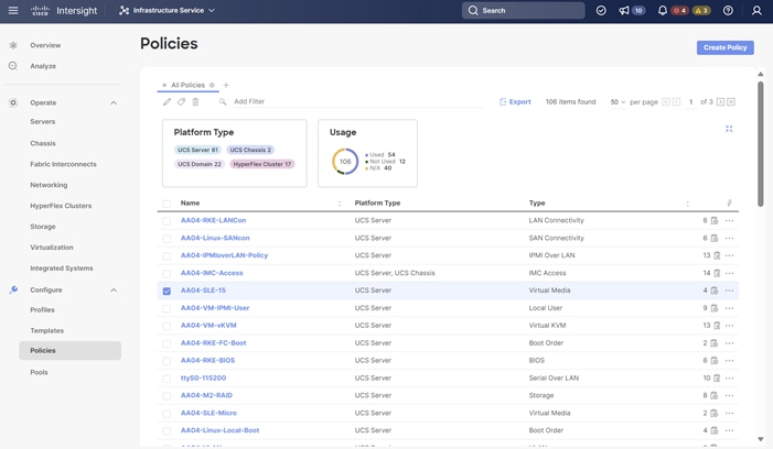
Step 2. Click the ellipses and click Edit:
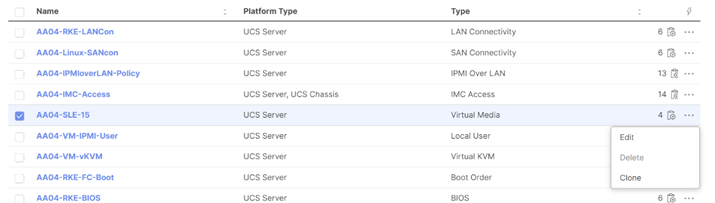
Step 3. Under Policy Details, click Add Virtual Media:

Step 4. Select the protocol and enter the required details to access the ISO image. We used HTTP on the management node. Click Add:
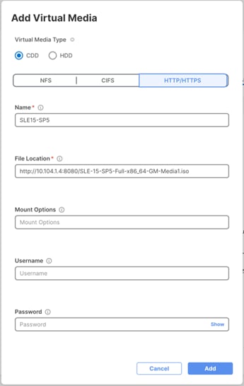
Step 5. Click Safe and Deploy:
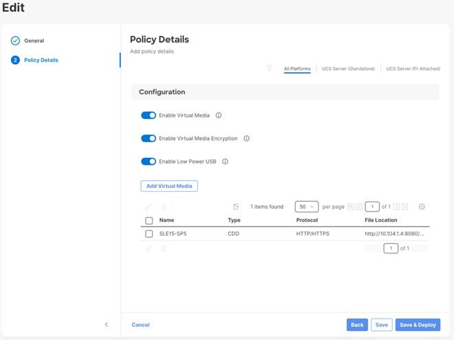
The vMedia policy gets activated on all UCS Server Profiles created with the Template:
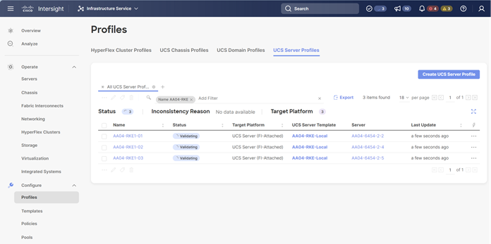
Note: Wait until the deployment of the vMedia policy is finished on all nodes before continuing to the next step.
Procedure 3. Install SUSE Linux Enterprise
Step 1. Under Profiles or Servers, click the ellipses and open a vKVM.
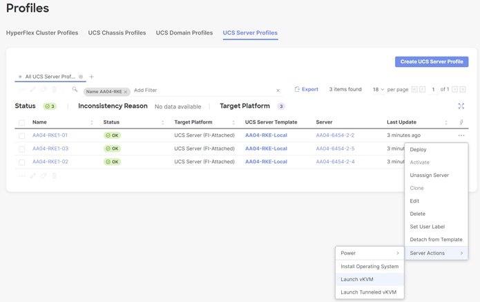
Step 2. Power on or reset the server to boot from the ISO image defined in the vMedia policy.
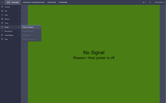
Step 3. Follow the SUSE Linux Enterprise installation.
Note: This document does not provide a comprehensive installation. Please use the default settings or the settings that fit best to your local installation.
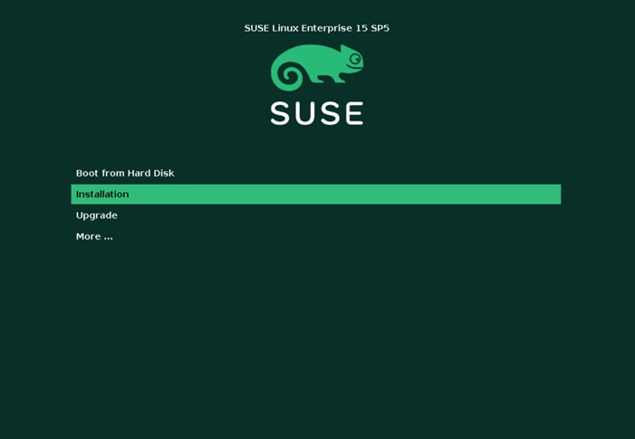
Step 4. Select SUSE Linux Enterprise Server 15 SP5 and click Next.
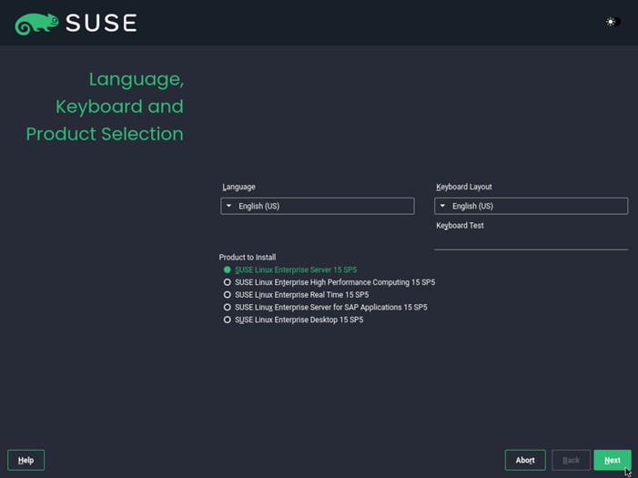
Step 5. Under Extension and Module Selection, select Basesystem Module and click Next. Selecting the Containers Module is optional.
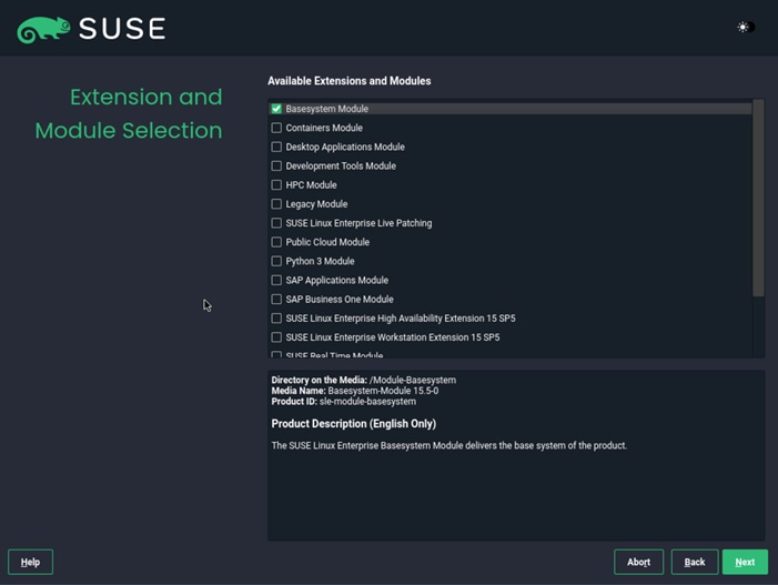
Step 6. Under System Role, select Text Mode and click Next.
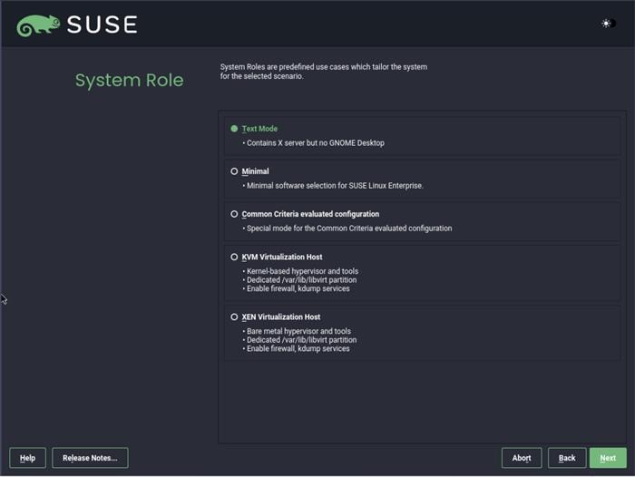
Note: It is required to configure NTP on all servers used for RKE.
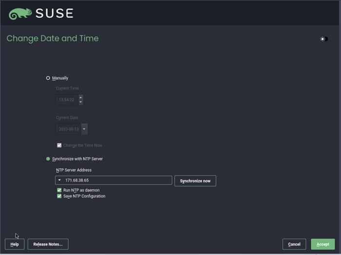
Step 7. Configure the filesystems using the guided setup.
Note: Do not create a separate partition for /home since no user will work on this host and the storage is required for the containers.
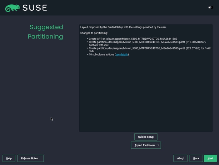
Step 8. Configure the network adapters as required for the installation. We used DHCP to configure the network, so the configuration is left as it is.
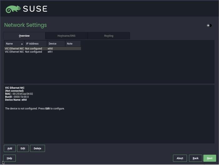
After the OS installation is finished the server will reboot automatically into the installed SLE15 SP5 system.
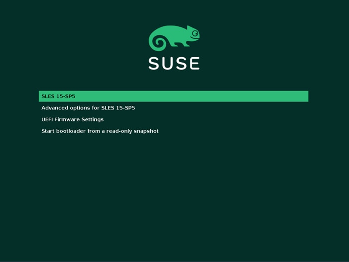
The IP addresses should be configured correctly using DHCP.
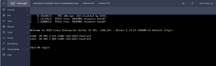
Step 9. If not already done, register the systems with SUSE to get access to the online software repositories and updates.
# suseconnect --email ukl*****@cisco.com --regcode **********
Registering system to SUSE Customer Center
Using E-Mail:ukl*****@cisco.com
Announcing system to https://scc.suse.com ...
Activating SLES 15.4 x86_64 ...
-> Adding service to system ...
Activating sle-module-basesystem 15.4 x86_64 ...
-> Adding service to system ...
-> Installing release package ...
Successfully registered system
#
There are a few tasks to complete the RKE2 cluster installation.
Note: For more information, go to the official Rancher installation site: https://ranchermanager.docs.rancher.com/how-to-guides/new-user-guides/kubernetes-cluster-setup/rke2-for-rancher
Procedure 1. Create the Initial RKE2 Cluster Configuration
Step 1. Create the base directory for RKE2 configuration files on all nodes:
# mkdir -p /etc/rancher/rke2/
Step 2. Create the configuration file for the RKE2 cluster based on your requirements, as documented here: https://docs.rke2.io/install/configuration.
# cat /etc/rancher/rke2/config.yaml
tls-san:
- lb.rke1.aa04.cspgb4.local
#
Procedure 2. Install RKE2 on the first node
The installation process occurs in multiple steps. The first step is to install the RKE2 software on the first node of the cluster. The parameter INSTALL_RKE2_VERSION is optional. Without this option, the latest version will be installed.
Step 1. Run the following command:
# curl -sfL https://get.rke2.io | INSTALL_RKE2_VERSION=v1.27.10+rke1r1 sh -
[WARN] /usr/local is read-only or a mount point; installing to /opt/rke2
[INFO] finding release for channel stable
[INFO] using v1.26.9+rke2r1 as release
[INFO] downloading checksums at https://github.com/rancher/rke2/releases/download/v1.27.10+rke2r1/sha256sum-amd64.txt
[INFO] downloading tarball at https://github.com/rancher/rke2/releases/download/v1.27.10+rke2r1/rke2.linux-amd64.tar.gz
[INFO] verifying tarball
[INFO] unpacking tarball file to /opt/rke2
[INFO] updating tarball contents to reflect install path
[INFO] moving systemd units to /etc/systemd/system
[INFO] install complete; you may want to run: export PATH=$PATH:/opt/rke2/bin
#
Step 2. Enable and start RKE2 system service:
# systemctl enable rke2-server.service
Created symlink /etc/systemd/system/multi-user.target.wants/rke2-server.service → /etc/systemd/system/rke2-server.service.
# systemctl start rke2-server.service
#
Step 3. Get the created node-token required for the remaining nodes to join the new cluster:
# cat /var/lib/rancher/rke2/server/node-token
K106e0830a692917add44738d1f2c77a1f76507613f4e15f30bf9f65c448f03f87b::server:7f6068a0ee66da0b88aa5b9a23dcb37e
#
Procedure 3. Check the RKE2 installation status on the first node
The installation process on the first node will up to 30 minutes.
Step 1. Check the list of RKE2 nodes in the cluster. Only the first node should be listed:
# /var/lib/rancher/rke2/bin/kubectl --kubeconfig /etc/rancher/rke2/rke2.yaml get nodes
NAME STATUS ROLES AGE VERSION
rke1-01 Ready control-plane,etcd,master 90s v1.27.10+rke2r1
#
Step 2. Check the running pods in the cluster. All entries must be either in the Running or Completed state:
# /var/lib/rancher/rke2/bin/kubectl --kubeconfig /etc/rancher/rke2/rke2.yaml get pods -A
NAMESPACE NAME READY STATUS RESTARTS AGE
kube-system cloud-controller-manager-rke1-01 1/1 Running 0 89s
kube-system etcd-rke1-01 1/1 Running 0 86s
kube-system helm-install-rke2-canal-g57sh 0/1 Completed 0 76s
kube-system helm-install-rke2-coredns-fcvvl 0/1 Completed 0 76s
kube-system helm-install-rke2-ingress-nginx-hn7ps 0/1 Completed 0 76s
kube-system helm-install-rke2-metrics-server-g6lbs 0/1 Completed 0 76s
kube-system helm-install-rke2-snapshot-controller-crd-mltgk 0/1 Completed 0 76s
kube-system helm-install-rke2-snapshot-controller-tcfx9 0/1 Completed 2 76s
kube-system helm-install-rke2-snapshot-validation-webhook-c28r8 0/1 Completed 0 76s
kube-system kube-apiserver-rke1-01 1/1 Running 0 90s
kube-system kube-controller-manager-rke1-01 1/1 Running 0 91s
kube-system kube-proxy-rke1-01 1/1 Running 0 85s
kube-system kube-scheduler-rke1-01 1/1 Running 0 91s
kube-system rke2-canal-d546x 2/2 Running 0 69s
kube-system rke2-coredns-rke2-coredns-7c98b7488c-588vx 1/1 Running 0 70s
kube-system rke2-coredns-rke2-coredns-autoscaler-65b5bfc754-4bxg5 1/1 Running 0 70s
kube-system rke2-ingress-nginx-controller-zs2l9 1/1 Running 0 35s
kube-system rke2-metrics-server-5bf59cdccb-kf52d 1/1 Running 0 43s
kube-system rke2-snapshot-controller-6f7bbb497d-p8wvq 1/1 Running 0 22s
kube-system rke2-snapshot-validation-webhook-65b5675d5c-rjxmv 1/1 Running 0 43s
#
Procedure 4. Install RKE2 on the remaining nodes
Step 1. Create the configuration file on every remaining node to join the cluster.
Note: It is important to add the node-token and the server entry with the ip address from the first node.
# cat /etc/rancher/rke2/config.yaml
token: “K106e0830a692917add44738d1f2c77a1f76507613f4e15f30bf9f65c448f03f87b::server:7f6068a0ee66da0b88aa5b9a23dcb37e”
server: https://10.104.3.31:9345
tls-san:
- lb.rke1.aa04.cspgb4.local
#
Step 2. Install RKE2 software on remaining nodes:
# curl -sfL https://get.rke2.io | INSTALL_RKE2_VERSION=v1.27.10+rke1r1 sh -
[WARN] /usr/local is read-only or a mount point; installing to /opt/rke2
[INFO] finding release for channel stable
[INFO] using v1.26.9+rke2r1 as release
[INFO] downloading checksums at https://github.com/rancher/rke2/releases/download/v1.27.10+rke2r1/sha256sum-amd64.txt
[INFO] downloading tarball at https://github.com/rancher/rke2/releases/download/v1.27.10+rke2r1/rke2.linux-amd64.tar.gz
[INFO] verifying tarball
[INFO] unpacking tarball file to /opt/rke2
[INFO] updating tarball contents to reflect install path
[INFO] moving systemd units to /etc/systemd/system
[INFO] install complete; you may want to run: export PATH=$PATH:/opt/rke2/bin
rke1-02:~ #
Step 3. Create the configuration file on every remaining node to join the cluster one after the other:
# systemctl enable rke2-server.service
Created symlink /etc/systemd/system/multi-user.target.wants/rke2-server.service → /etc/systemd/system/rke2-server.service.
# systemctl start rke2-server.service
Procedure 5. Check the RKE2 cluster installation
Note: Before you install SUSE Rancher RKE2, download the helm package client (helm) to the management node.
Step 1. Run the following command on one of the nodes to list all nodes in the cluster:
# /var/lib/rancher/rke2/bin/kubectl --kubeconfig /etc/rancher/rke2/rke2.yaml get nodes
NAME STATUS ROLES AGE VERSION
rke1-01 Ready control-plane,etcd,master 19m v1.27.10+rke2r1
rke1-02 Ready control-plane,etcd,master 12m v1.27.10+rke2r1
rke1-03 Ready control-plane,etcd,master 33s v1.27.10+rke2r1
#
Step 2. Run the following command on one of the nodes to see the state of all pods:
# /var/lib/rancher/rke2/bin/kubectl --kubeconfig /etc/rancher/rke2/rke2.yaml get pods -A
NAMESPACE NAME READY STATUS RESTARTS AGE
kube-system cloud-controller-manager-rke1-01 1/1 Running 0 21m
kube-system cloud-controller-manager-rke1-02 1/1 Running 0 14m
kube-system cloud-controller-manager-rke1-03 1/1 Running 0 2m54s
kube-system etcd-rke1-01 1/1 Running 0 21m
kube-system etcd-rke1-02 1/1 Running 0 14m
kube-system etcd-rke1-03 1/1 Running 0 2m27s
kube-system helm-install-rke2-canal-g57sh 0/1 Completed 0 21m
kube-system helm-install-rke2-coredns-fcvvl 0/1 Completed 0 21m
kube-system helm-install-rke2-ingress-nginx-hn7ps 0/1 Completed 0 21m
kube-system helm-install-rke2-metrics-server-g6lbs 0/1 Completed 0 21m
kube-system helm-install-rke2-snapshot-controller-crd-mltgk 0/1 Completed 0 21m
kube-system helm-install-rke2-snapshot-controller-tcfx9 0/1 Completed 2 21m
kube-system helm-install-rke2-snapshot-validation-webhook-c28r8 0/1 Completed 0 21m
kube-system kube-apiserver-rke1-01 1/1 Running 0 21m
kube-system kube-apiserver-rke1-02 1/1 Running 0 14m
kube-system kube-apiserver-rke1-03 1/1 Running 0 2m19s
kube-system kube-controller-manager-rke1-01 1/1 Running 0 21m
kube-system kube-controller-manager-rke1-02 1/1 Running 0 14m
kube-system kube-controller-manager-rke1-03 1/1 Running 0 2m54s
kube-system kube-proxy-rke1-01 1/1 Running 0 21m
kube-system kube-proxy-rke1-02 1/1 Running 0 14m
kube-system kube-proxy-rke1-03 1/1 Running 0 2m50s
kube-system kube-scheduler-rke1-01 1/1 Running 0 21m
kube-system kube-scheduler-rke1-02 1/1 Running 0 14m
kube-system kube-scheduler-rke1-03 1/1 Running 0 2m54s
kube-system rke2-canal-46qq7 2/2 Running 0 14m
kube-system rke2-canal-d546x 2/2 Running 0 21m
kube-system rke2-canal-qj4mw 2/2 Running 0 3m9s
kube-system rke2-coredns-rke2-coredns-7c98b7488c-588vx 1/1 Running 0 21m
kube-system rke2-coredns-rke2-coredns-7c98b7488c-hbsjl 1/1 Running 0 14m
kube-system rke2-coredns-rke2-coredns-autoscaler-65b5bfc754-4bxg5 1/1 Running 0 21m
kube-system rke2-ingress-nginx-controller-bl679 1/1 Running 0 14m
kube-system rke2-ingress-nginx-controller-zs2l9 1/1 Running 0 20m
kube-system rke2-ingress-nginx-controller-zz6w4 1/1 Running 0 2m53s
kube-system rke2-metrics-server-5bf59cdccb-kf52d 1/1 Running 0 21m
kube-system rke2-snapshot-controller-6f7bbb497d-p8wvq 1/1 Running 0 20m
kube-system rke2-snapshot-validation-webhook-65b5675d5c-rjxmv 1/1 Running 0 21m
#
Procedure 6. Copy the kubeconfig file to the management node
Step 1. Run the following command on the management node:
# scp 10.104.3.91:/etc/rancher/rke2/rke2.yaml ./kube
# mv .kube/rke2.yaml config
Step 2. Change the server entry in the config file to match the load balancer IP for the installed cluster:
# cat .kube/config | grep server
server: https://lb.rke1.aa04.cspgb4.local:6443
#
This section contains the following:
· Prepare the RKE2 luster for the Rancher installation
· Install Rancher on Three Node RKE2 Cluster
Procedure 1. Prepare the RKE2 Cluster for the Rancher installation
Step 1. Create the namespace for Rancher (default is cattle-system):
# kubectl create namespace cattle-system
Step 2. Add the Rancher helm repository to the system:
# helm repo add rancher-stable https://releases.rancher.com/server-charts/stable
# helm repo update
Step 3. Check for the latest Rancher versions in the repository:
# helm search repo --versions | head
NAME CHART VERSION APP VERSION DESCRIPTION
rancher-stable/rancher 2.8.2 v2.8.2 Install Rancher Server to manage Kubernetes clu...
rancher-stable/rancher 2.8.1 v2.8.1 Install Rancher Server to manage Kubernetes clu...
rancher-stable/rancher 2.7.10 v2.7.10 Install Rancher Server to manage Kubernetes clu...
rancher-stable/rancher 2.7.9 v2.7.9 Install Rancher Server to manage Kubernetes clu...
rancher-stable/rancher 2.7.6 v2.7.6 Install Rancher Server to manage Kubernetes clu...
rancher-stable/rancher 2.7.5 v2.7.5 Install Rancher Server to manage Kubernetes clu...
rancher-stable/rancher 2.7.4 v2.7.4 Install Rancher Server to manage Kubernetes clu...
rancher-stable/rancher 2.7.3 v2.7.3 Install Rancher Server to manage Kubernetes clu...
rancher-stable/rancher 2.7.2 v2.7.2 Install Rancher Server to manage Kubernetes clu...
sle-mgmt01:~ #
Procedure 2. Install Cert-manager
Step 1. To use Rancher managed certificates it is required to install the cert-manager on the cluster. Run the following commands:
# kubectl apply -f https://github.com/cert-manager/cert-manager/releases/download/v1.11.0/cert-manag
er.crds.yaml
# helm repo add jetstack https://charts.jetstack.io
# helm repo update
# helm install cert-manager jetstack/cert-manager \
--namespace cert-manager \
--create-namespace \
--version v1.11.0
Step 2. Check that the cert-manager installation was successful:
# kubectl get pods --namespace cert-manager
NAME READY STATUS RESTARTS AGE
cert-manager-64f9f45d6f-ppl8z 1/1 Running 0 87s
cert-manager-cainjector-56bbdd5c47-9tkc4 1/1 Running 0 87s
cert-manager-webhook-d4f4545d7-rqqkc 1/1 Running 0 87s
#
Procedure 3. Install Rancher on Three Node RKE2 Cluster
Step 1. Run the following command to initiate the Rancher installation:
# sle-mgmt01:~ # helm install rancher rancher-stable/rancher \
--namespace cattle-system \
--set hostname=rancher.rke1.aa04.cspgb4.local \
--set bootstrapPassword=H1g*******24
Step 2. Monitor the installation progress by running the following commands:
# kubectl -n cattle-system rollout status deploy/rancher
Waiting for deployment "rancher" rollout to finish: 1 of 3 updated replicas are available...
Waiting for deployment "rancher" rollout to finish: 2 of 3 updated replicas are available...
deployment "rancher" successfully rolled out
sle-mgmt01:~ #
sle-mgmt01:~ # kubectl -n cattle-system get deploy rancher
NAME READY UP-TO-DATE AVAILABLE AGE
rancher 3/3 3 3 113s
#
Step 3. Open a web browser, like Google Chrome, and navigate to the hostname provided in the rancher installation procedure. We used rancher.rke1.aa04.cspgb4.local as the hostname.
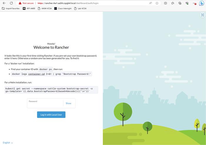
Step 4. If no password for user admin was specified at installation time run the following command to get the generated password for the user admin:
# kubectl get secret --namespace cattle-system bootstrap-secret \
-o go-template='{{.data.bootstrapPassword|base64decode}}{{"\n"}}'
Step 5. Use the password to log on and accept the EUL as shown below:
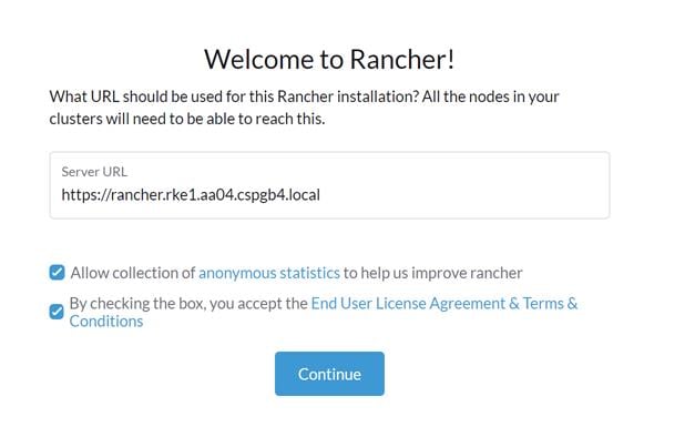
The Rancher home screen is shown below:
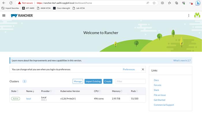
Deployment Option with SUSE SLE Micro and K3s
If a deployment based on SUSE Linux Enterprise 15 and RKE2 is too big or if a simplified and downsized container optimized stack is required, the deployment with SUSE SLE Micro and K3s is a viable option. This stack can be deployed as a single node stack – i.e. for non-production systems, or as multi-node stack with full high availability.
SUSE Linux Enterprise Micro 5 Installation
Procedure 1. Prepare SUSE Linux Enterprise Micro installation
Step 1. Download the SUSE Linux Enterprise Micro 5.x ISO image from the SUSE web site and store it on a place reachable from the OOB_Management network. We used the management node under /srv/www/htdocs.
# ls -l /srv/www/htdocs/
total 18675712
-rw-r--r-- 1 root root 2034237440 Oct 6 14:46 SLE-Micro-5.4-DVD-x86_64-GM-Media1.iso
#
Procedure 2. Update the vMedia Policy in Intersight
Step 1. Open Intersight and browse to Configure – Policies and select the vMedia policy created for this installation, we used AA05-SLE-15.
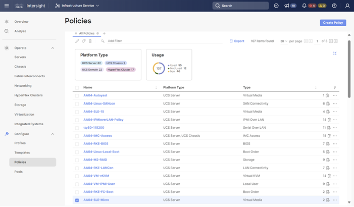
Step 2. Click the ellipses and select Edit.
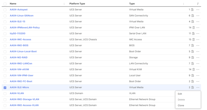
Step 3. Under Policy Details, click Add Virtual Media.
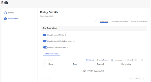
Step 4. Select the protocol and enter the required details to access the ISO image. We have used HTTP on the management node. Click Add.
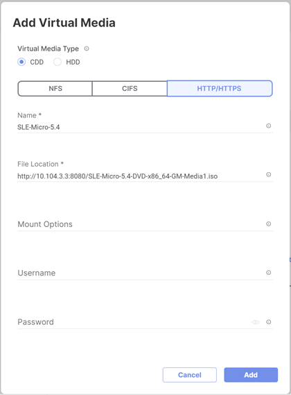
Step 5. Click Safe and Deploy.
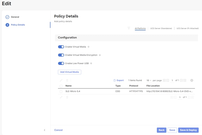
The vMedia policy gets activated on all Server Profiles created with the template:
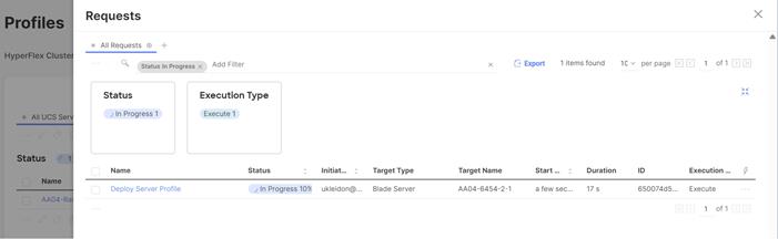
Note: Wait until the deployment of the vMedia policy is finished on all nodes before continuing with the next step.
Procedure 3. Install SUSE Linux Enterprise Micro
Step 1. Under Profiles or Servers, click the ellipses and open a vKVM.
![]()
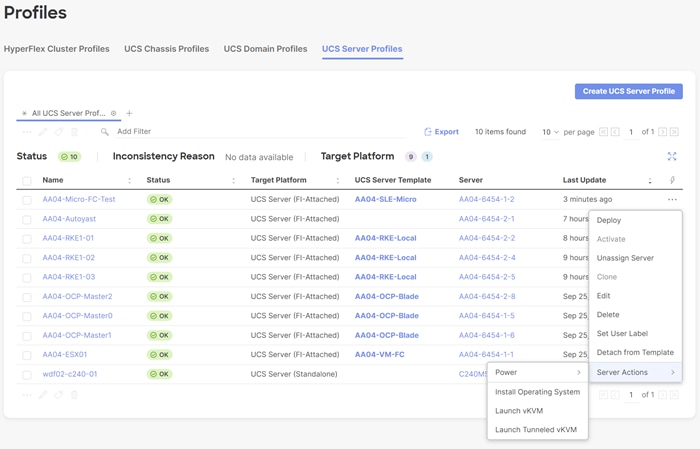
Step 2. Power on or reset the server to boot from the ISO image defined in the vMedia policy.
Step 3. Follow the SUSE Linux Enterprise installation.
Note: This document does not provide a comprehensive installation. Please use the default settings or the set-tings that fit best to your local installation.
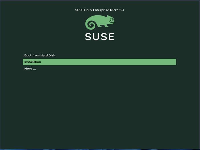
Step 4. Configure the network adapters as required for the installation. We used DHCP to configure the network, so the configuration is left as it is.
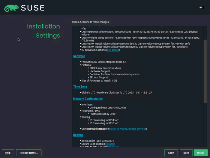
Note: It is required to configure NTP on all servers used for RKE.
Step 5. After the OS installation is finished the server will reboot.
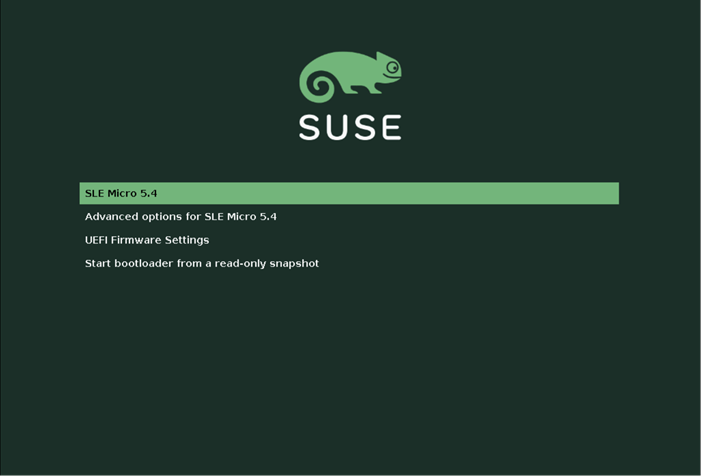
Step 6. After the system is booted you can log on as user root.
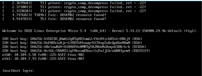
Step 7. If not already done, register the systems with SUSE to get access to the online software repositories and updates:
# suseconnect --email ukl*****@cisco.com --regcode **********
Registering system to SUSE Customer Center
Using E-Mail:ukl*****@cisco.com
Announcing system to https://scc.suse.com ...
Activating SLE-Micro 5.4 x86_64 ...
-> Adding service to system ...
Successfully registered system
#
SUSE K3s Installation on a Single Node
Procedure 1. Prepare K3s installation
Step 1. Run the following command to install the required apparmor-parser package and reboot the system after the installation:
# transactional-update pkg install apparmor-parser
reboot
Step 2. Disable the Linux Firewall:
# systemctl stop firewall
# systemctl disable firewall
Step 3. Create base directory:
# mkdir -p /etc/rancher/k3s
#
Procedure 2. Install K3s
Step 1. Check the web site for the release that is available: https://github.com/k3s-io/k3s/releases/. We chose v1.26.9+k3s1:
# export K3s_VERSION="v1.26.9+k3s1"
Step 2. Install K3s:
# curl -sfL https://get.k3s.io | \
INSTALL_K3S_VERSION=${K3s_VERSION} \
INSTALL_K3S_EXEC='server --cluster-init --write-kubeconfig-mode=644' \
sh -s -
Step 3. Check that the installation is finished by running the following commands:
# kubectl get nodes
NAME STATUS ROLES AGE VERSION
mic-rancher.aa04.cspgb4.local Ready control-plane,etcd,master 50s v1.26.9+k3s1
#
# kubectl get pods -A
NAMESPACE NAME READY STATUS RESTARTS AGE
kube-system coredns-59b4f5bbd5-7q9nh 1/1 Running 0 85s
kube-system helm-install-traefik-crd-gkz9n 0/1 Completed 0 85s
kube-system helm-install-traefik-ftfz5 0/1 Completed 1 85s
kube-system local-path-provisioner-76d776f6f9-k6vqs 1/1 Running 0 85s
kube-system metrics-server-68cf49699b-9s6mk 1/1 Running 0 85s
kube-system svclb-traefik-d1c53b56-rrmzh 2/2 Running 0 75s
kube-system traefik-57c84cf78d-r7wqm 1/1 Running 0 75s
#
Step 4. Copy the kubeconfig file to the management system:
# scp root@10.104.3.58://etc/rancher/k3s/k3s.yaml ~/.kube/config
Step 5. Change the server entry in the kubeconfig file to match the FQDN:
# grep server .kube/config
server: https://rancher.aa04.cspgb4.local:6443
mgmt01:~>
Step 6. Limit the permissions of the .kube/config file to be accessible from the owner only by running the following command:
# chmod 700 ~/.kube/config
Procedure 3. Install the cert-manager for Rancher managed certificates
Step 1. Create the namespace for the cert-manager, default is cert-manager:
# kubectl create namespace cert-manager
Step 2. Add the cert-manager crds to the system:
# kubectl apply --validate=false -f https://github.com/jetstack/cert-manager/releases/download/v1.0.4/cert-manager.crds.yaml
Step 3. Add the helm repository for the cert-manager to the system:
# helm repo add jetstack https://charts.jetstack.io
# helm repo update
Step 4. Install the cert-manager:
# helm install cert-manager jetstack/cert-manager --namespace cert-manager
Step 5. Check that the cert-manager installation has finished:
# kubectl get pods -n cert-manager
NAME READY STATUS RESTARTS AGE
cert-manager-675dccb56-k95vk 1/1 Running 0 31s
cert-manager-cainjector-759948cf7d-jfckc 1/1 Running 0 31s
cert-manager-webhook-78dd4b95b6-b4bb7 1/1 Running 0 31s
#
Procedure 4. Install SUSE Rancher on K3s
Step 1. Create the namespace for the Rancher installation, default is cattle-system:
# kubectl create namespace cattle-system
Step 2. Add the helm repository for Rancher to the system:
# helm repo add rancher-stable https://releases.rancher.com/server-charts/stable
# helm repo update
Step 3. List the available Rancher versions:
# helm search repo --versions | head
NAME CHART VERSION APP VERSION DESCRIPTION
rancher-stable/rancher 2.7.6 v2.7.6 Install Rancher Server to manage Kubernetes clu...
rancher-stable/rancher 2.7.5 v2.7.5 Install Rancher Server to manage Kubernetes clu...
rancher-stable/rancher 2.7.4 v2.7.4 Install Rancher Server to manage Kubernetes clu...
rancher-stable/rancher 2.7.3 v2.7.3 Install Rancher Server to manage Kubernetes clu...
rancher-stable/rancher 2.7.2 v2.7.2 Install Rancher Server to manage Kubernetes clu...
rancher-stable/rancher 2.7.1 v2.7.1 Install Rancher Server to manage Kubernetes clu...
rancher-stable/rancher 2.7.0 v2.7.0 Install Rancher Server to manage Kubernetes clu...
Step 4. Install Rancher:
# helm install rancher rancher-stable/rancher --namespace cattle-system --set hostname=rancher.aa04.cspgb4.local
Step 5. Monitor the Rancher installation:
# kubectl -n cattle-system rollout status deploy/rancher
Waiting for deployment "rancher" rollout to finish: 0 of 3 updated replicas are available...
Waiting for deployment "rancher" rollout to finish: 1 of 3 updated replicas are available...
Waiting for deployment "rancher" rollout to finish: 2 of 3 updated replicas are available...
deployment "rancher" successfully rolled out
#
Step 6. Run the following command to get the initial password for the admin user:
# kubectl get secret --namespace cattle-system bootstrap-secret -o go-template='{{.data.boots
trapPassword|base64decode}}{{"\n"}}'
4x7rtzwxgqmhfn6gqdl9j24gz25jdmnq72wlcxqb8646w4t5c8jqws
#
Step 7. Open a web browser and navigate to the hostname given at installation time, we used rancher.aa04.cspgb4.local.
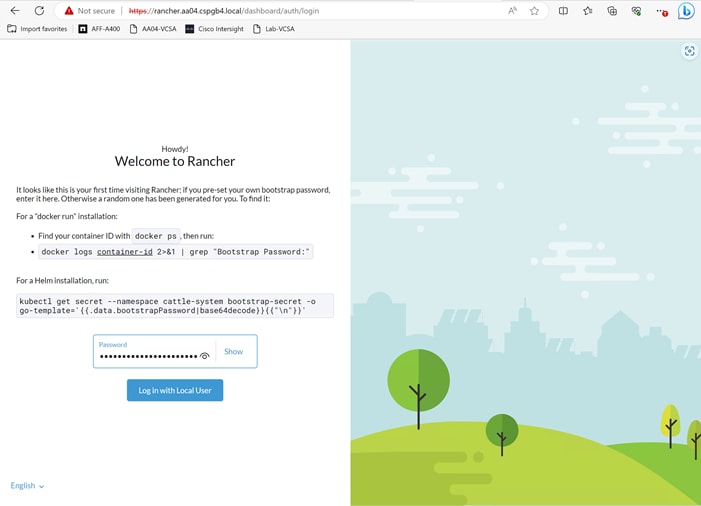
Step 8. Set a new password for the admin user and accept the EUL.

The Rancher home screen displays with the list of available clusters:
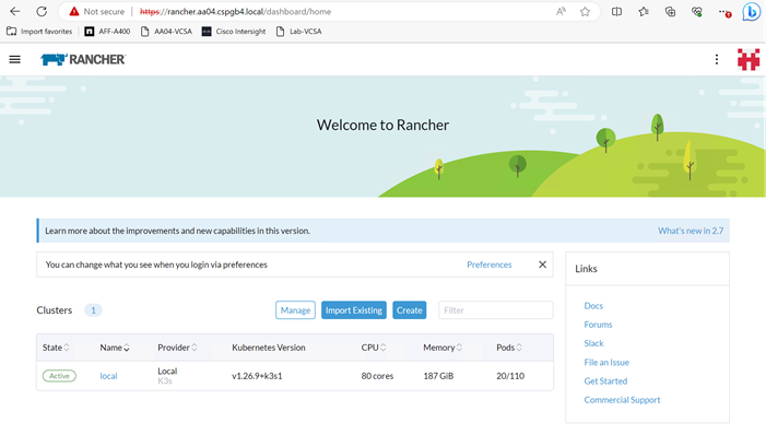
Procedure 5. Add an existing Kubernetes cluster to Rancher
To add or import existing Kubernetes clusters to Rancher follow these steps:
Step 1. Open the Rancher UI and click on Import Existing in the home screen.
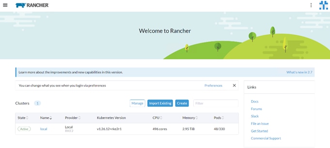
Step 2. Click Generic.
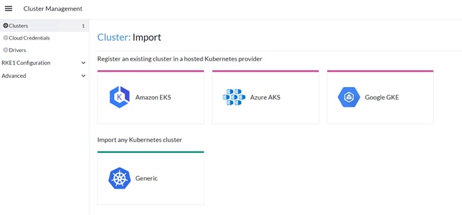
Step 3. Enter a name for the cluster and click Create.
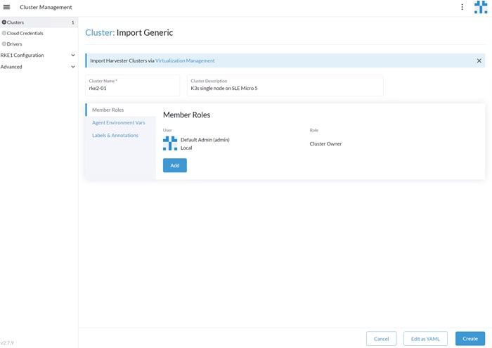
Step 4. Copy one of the command options on against the installed Kubernetes cluster:
# curl --insecure -sfL https://rancher.rke1.aa04.cspgb4.local/v3/import/gpdcr64zlkg6ncp2bn7j4vgpw9lztgp9kcdlcwnd5x8rz9bqkg5slx_c-m-4bbqxtpl.yaml | kubectl apply -f -
clusterrole.rbac.authorization.k8s.io/proxy-clusterrole-kubeapiserver created
clusterrolebinding.rbac.authorization.k8s.io/proxy-role-binding-kubernetes-master created
namespace/cattle-system created
serviceaccount/cattle created
clusterrolebinding.rbac.authorization.k8s.io/cattle-admin-binding created
secret/cattle-credentials-74cb064 created
clusterrole.rbac.authorization.k8s.io/cattle-admin created
Warning: spec.template.spec.affinity.nodeAffinity.requiredDuringSchedulingIgnoredDuringExecution.nodeSelectorTerms[0].matchExpressions[0].key: beta.kubernetes.io/os is deprecated since v1.14; use "kubernetes.io/os" instead
deployment.apps/cattle-cluster-agent created
service/cattle-cluster-agent created
#
Step 5. Check the installation by executing the following command:
# kubectl get pods -A
NAMESPACE NAME READY STATUS RESTARTS AGE
cattle-fleet-system fleet-agent-855db48487-k2jvz 1/1 Running 0 25s
cattle-system cattle-cluster-agent-54c67d7fc5-xslc4 1/1 Running 0 43s
cattle-system helm-operation-9nd7t 2/2 Running 0 22s
cattle-system rancher-webhook-85b57d6bf8-26hx7 0/1 Running 0 9s
kube-system coredns-59b4f5bbd5-z6rq9 1/1 Running 0 14m
kube-system helm-install-traefik-crd-wxn9j 0/1 Completed 0 14m
kube-system helm-install-traefik-j48bd 0/1 Completed 1 14m
kube-system local-path-provisioner-76d776f6f9-8dg44 1/1 Running 0 14m
kube-system metrics-server-68cf49699b-cnwzc 1/1 Running 0 14m
kube-system svclb-traefik-3045b76f-blq54 2/2 Running 0 14m
kube-system traefik-57c84cf78d-m7mfl 1/1 Running 0 14m
#
The new cluster is now visible in Rancher:
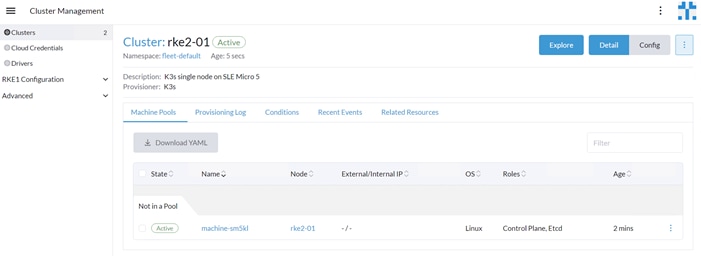
Deploy and Configure NetApp Astra Trident
Astra Trident is an open-source, fully supported storage orchestrator for containers and Kubernetes distributions. It was designed to help meet the containerized applications’ persistence demands using industry-standard interfaces, such as the Container Storage Interface (CSI). With Astra Trident, microservices and containerized applications can take advantage of enterprise-class storage services provided by NetApp portfolio of storage systems. More information about Trident can be found here: NetApp Trident Documentation.
Note: In this solution, we validated NetApp Trident with ontap-nas driver using the NFS protocol.
NetApp Astra Trident Deployment
Procedure 1. Deploy NetApp Astra Trident
Step 1. Download Trident software from GitHub and untar the .gz file to obtain the trident-installer folder:
# wget https://github.com/NetApp/trident/releases/download/v24.02.0/trident-installer-24.02.0.tar.gz
Saving to: ‘trident-installer-24.02.0.tar.gz’
# tar –xf trident-installer-24.02.0.tar.gz
# cd trident-installer/helm
Step 2. Create the trident namespace:
kubectl create namespace trident
Step 3. Create the CRD:
# helm install trident trident-operator-100.2402.0.tgz -n trident
NAME: trident
---
NAMESPACE: trident
STATUS: deployed
REVISION: 1
TEST SUITE: None
NOTES:
Thank you for installing trident-operator, which will deploy and manage NetApp's Trident CSI
storage provisioner for Kubernetes.
Your release is named 'trident' and is installed into the 'trident' namespace.
Please note that there must be only one instance of Trident (and trident-operator) in a Kubernetes cluster.
To configure Trident to manage storage resources, you will need a copy of tridentctl, which is
available in pre-packaged Trident releases. You may find all Trident releases and source code
online at https://github.com/NetApp/trident.
To learn more about the release, try:
$ helm status trident
$ helm get all trident customresourcedefinition.apiextensions.k8s.io/tridentorchestrators.trident.netapp.io created
Step 4. At this point, verify the operator, deployment, and replicasets are created:
sle-mgmt:~ # kubectl get all -n trident
NAME READY STATUS RESTARTS AGE
pod/trident-controller-999fb7869-t67nz 6/6 Running 0 3m37s
pod/trident-node-linux-4bxtt 2/2 Running 0 3m37s
pod/trident-node-linux-q26z6 2/2 Running 0 3m37s
pod/trident-node-linux-z5dzs 2/2 Running 0 3m37s
pod/trident-operator-69975c4fbc-pgkkp 1/1 Running 0 6m46s
NAME TYPE CLUSTER-IP EXTERNAL-IP PORT(S) AGE
service/trident-csi ClusterIP 10.43.134.246 <none> 34571/TCP,9220/TCP 3m37s
NAME DESIRED CURRENT READY UP-TO-DATE AVAILABLE NODE SELECTOR AGE
daemonset.apps/trident-node-linux 3 3 3 3 3 <none> 3m37s
NAME READY UP-TO-DATE AVAILABLE AGE
deployment.apps/trident-controller 1/1 1 1 3m37s
deployment.apps/trident-operator 1/1 1 1 6m27s
NAME DESIRED CURRENT READY AGE
replicaset.apps/trident-controller-999fb7869 1 1 1 3m37s
replicaset.apps/trident-operator-69975c4fbc 1 1 1 6m46s
Note: If the Astra Trident deployment fails and does not bring up the pods to Running state, use the tridentctl logs -l all -n trident command for debugging.
Step 5. Verify the Server and Client version again:
# tridentctl version -n trident
+----------------+----------------+
| SERVER VERSION | CLIENT VERSION |
+----------------+----------------+
| 24.02.0 | 24.02.0 |
+----------------+----------------+
Note: Before configuring the backend that Trident needs to use for user apps, go to: https://docs.netapp.com/us-en/trident/trident-reference/objects.html#kubernetes-customresourcedefinition-objects to understand the storage environment parameters and its usage in Trident.
Procedure 2. Configure the Storage Backend in Trident
Step 1. Configure the connection to the SVM on the NetApp storage array created for the RKE2 cluster. For more options regarding storage backend configuration, go to: https://docs.netapp.com/us-en/trident/trident-use/backends.html
Procedure 3. Backend definition for ONTAP NAS drivers
Step 1. Create configuration for the Trident backend configuration:
# cat << EOF > ontapnas-backend.json
{
"version": 1,
"storageDriverName": "ontap-nas",
"backendName": "rke-bm-nfs-backend",
"managementLIF": "10.107.0.10",
"dataLIF": "10.104.7.204",
"svm": "AA04-RKE2-BM-SVM",
"username": "******",
"password": "******"
}
EOF
Step 2. Deploy the Trident Backend configuration:
sle-mgmt:~ # tridentctl create backend -f ontapnas-backend.json -n trident
+--------------------+---------------------+--------------------------------------+--------+------------+---------+
| NAME | STORAGE DRIVER | UUID | STATE | USER-STATE | VOLUMES |
+--------------------+---------------------+--------------------------------------+--------+------------+---------+
| rke-bm-nfs-backend | ontap-nas | 18b436fb-4012-415f-8113-5e9c0f9f4328 | online | normal | 0 |
+--------------------+---------------------+--------------------------------------+--------+------------+---------+
Step 3. Backend definition for ONTAP FlexGroup driver:
For information about FlexGroups and workloads that are appropriate for FlexGroups see the NetApp FlexGroup Volume Best Practices and Implementation Guide.
# cat << EOF > backend_NFS_flexgroup.json
{
"version": 1,
"storageDriverName": "ontap-nas-flexgroup",
"backendName": " FlexGrpBackendName",
"managementLIF": "10.107.0.10",
"dataLIF": "10.104.7.203",
"svm": " AA04-RKE2-BM-SVM",
"username": "flexadmin",
"password": "********",
"defaults": {
"spaceReserve": "volume",
"exportPolicy": "default",
"snapshotPolicy": "default",
"snapshotReserve": "10"
}
}
Step 4. Activate the backend storage configuration:
sle-mgmt:~ # tridentctl create backend -f flexgroup-backend.json -n trident
+--------------------+---------------------+--------------------------------------+--------+------------+---------+
| NAME | STORAGE DRIVER | UUID | STATE | USER-STATE | VOLUMES |
+--------------------+---------------------+--------------------------------------+--------+------------+---------+
| FlexGrpBackendName | ontap-nas-flexgroup | a17efe47-041b-414a-ba66-6c98d8b6eb36 | online | normal | 0 |
+--------------------+---------------------+--------------------------------------+--------+------------+---------+
Step 5. Configure a storage class for ontap-nas and ontap-nas-flexgroup and make ontap-nas as default storage class:
# cat << EOF > storage-class-nfs-csi.yaml
apiVersion: storage.k8s.io/v1
kind: StorageClass
metadata:
name: ontap-gold
annotations:
storageclass.kubernetes.io/is-default-class: "true"
provisioner: csi.trident.netapp.io
parameters:
backendType: "ontap-nas"
provisioningType: "thin"
snapshots: "true"
EOF
#
#
# kubectl create -f storage-class-nfs-csi.yaml
storageclass.storage.k8s.io/ontap-gold created
#
Step 6. Create storage class configuration file:
# cat << EOF > storage-class-flexgroup-nfs-csi.yaml
apiVersion: storage.k8s.io/v1
kind: StorageClass
metadata:
name: ontap-nas-flxgrp
annotations:
provisioner: csi.trident.netapp.io
parameters:
backendType: "ontap-nas-flexgroup"
media: ssd
provisioningType: "thin"
snapshots: "true"
reclaimPolicy: Delete
volumeBindingMode: Immediate
EOF
#
Step 7. Create storage class for RKE cluster:
# kubectl create -f storage-class-flexgroup-nfs-csi.yaml
storageclass.storage.k8s.io/ontap-nas-flxgrp created
#
# kubectl get sc
NAME PROVISIONER RECLAIMPOLICY VOLUMEBINDINGMODE ALLOWVOLUMEEXPANSION AGE
ontap-gold (default) csi.trident.netapp.io Delete Immediate true 14m
ontap-nas-flxgrp csi.trident.netapp.io Delete Immediate false 7m
Step 8. Create Volume Snapshot class for the RKE cluster:
# cat snapshot-class-csi.yaml
apiVersion: snapshot.storage.k8s.io/v1
kind: VolumeSnapshotClass
metadata:
name: trident-snapshotclass
driver: csi.trident.netapp.io
deletionPolicy: Delete
# kubectl create -f snapshot-class-csi.yaml
volumesnapshotclass.snapshot.storage.k8s.io/trident-snapshotclass created
This completes the NetApp Astra Trident installation and configuration.
GPU Enablement and AI Workloads
This chapter contains the following:
· Container Creation with NVIDIA Driver, CUDA-Operator, and Toolkit
· Deploy NetApp DataOps Toolkit
· Deploy NVIDIA License Server
· Deploy NetApp DataOps Toolkit
Graphics Processing Units (GPUs) provide unique capabilities for accelerating a broad spectrum of workloads, such as artificial intelligence and machine learning, scientific and engineering simulations, and many more. Developing and deploying these workloads in containers on Kubernetes clusters offers potential for improved portability, scale, and efficiency. However, GPU resources are not automatically visible or accessible to workloads running in containers.
Container Creation with NVIDIA Driver, CUDA-Operator, and Toolkit
To create the container images with the required NVIDIA drivers, the CUDA-Operator, and the CUDA-Toolkit based on SUSE Linux Enterprise Base Container Images (SLE BCI), a system called build node is required. The build node can be a bare-metal server or a virtual machine running SUSE Linux Enterprise – if possible, on the same version as the target RKE2 cluster.
Note: Please double check the supported kernel versions for the NVIDIA drivers and CUDA software. In this validation we have used the unpatched SLE15 SP5 version due to some issues we saw with a patched kernel.
Procedure 1. Create Container with NVIDIA driver, CUDA-Operator, and Toolkit
Step 1. Enable the Containers, Desktop Applications, and Development Tools modules:
# VER=15
# SP=5
# sudo SUSEConnect -p sle-module-containers/${VER}.${SP}/x86_64
# sudo SUSEConnect -p sle-module-desktop-applications/${VER}.${SP}/x86_64
# sudo SUSEConnect -p sle-module-development-tools/${VER}.${SP}/x86_64
Step 2. Install podman. Podman, or Pod Manager Tool) is a daemonless container engine for managing Open Container Initiative containers:
# sudo zypper install podman
Step 3. Install Git. Git is a free and open source, distributed version control system that simplifies access to and management of source code:
# sudo zypper install git-core
Step 4. Create a file to set required versions for key components - ~/build-variables.sh.
◦ REGISTRY: URL of the registry where the new container image is to be saved
◦ SLE_VERSION: SUSE Linux Enterprise Base Container Images version
◦ SLE_SP: SUSE Linux Enterprise Base Container Images service pack number
◦ DRIVER_VERSION: NVIDIA GPU Driver version
Find the latest "Data Center Driver for Linux x64" version for your GPU at NVIDIA Driver Downloads.
◦ OPERATOR_VERSION: NVIDIA GPU Operator version
Find the associated NVIDIA GPU Operator version.
◦ CUDA_VERSION: the NVIDIA CUDA version appropriate for the selected NVIDIA GPU Driver
The CUDA version is listed under "Software Versions" when you find your driver version at NVIDIA Driver Downloads.
# cat <<EOF> /tmp/build-variables.sh
export REGISTRY="registry.gitlab.com/aa/rancher"
export SLE_VERSION="15"
export SLE_SP="5"
export DRIVER_VERSION="550.54.14"
export OPERATOR_VERSION="v23.9.1"
export CUDA_VERSION="12.3.2"
EOF
Step 5. Install required NVIDIA software package on each node:
# sudo zypper install \
kernel-firmware-nvidia \
libnvidia-container-tools \
libnvidia-container1 \
nvidia-container-runtime \
sle-module-NVIDIA-compute-release
Step 6. Source your build-variables.sh file:
# source ~/build-variables.sh
Step 7. Clone the NVIDIA driver GitLab repository and change to the driver/sle15 directory:
# git clone https://gitlab.com/nvidia/container-images/driver/ && cd driver/sle15
Step 8. Locate the file, Dockerfile, and update it to reflect your build requirements:
# cp Dockerfile /tmp/Dockerfile.orig
# sed -i "/^FROM/ s/golang\:1\.../golang\:1.18/" Dockerfile
# sed -i '/^FROM/ s/suse\/sle15/bci\/bci-base/' Dockerfile
# diff /tmp/Dockerfile.orig Dockerfile
Step 9. Run the podman build command, passing the necessary arguments:
# sudo podman build -t \
${REGISTRY}/nvidia-sle${SLE_VERSION}sp${SLE_SP}-${DRIVER_VERSION}:${DRIVER_VERSION} \
--build-arg SLES_VERSION="${SLE_VERSION}.${SLE_SP}" \
--build-arg DRIVER_ARCH="x86_64" \
--build-arg DRIVER_VERSION="${DRIVER_VERSION}" \
--build-arg CUDA_VERSION="${CUDA_VERSION}" \
--build-arg PRIVATE_KEY=empty \
.
Note: Watch the build process for errors, warnings, and failures. You can ignore everything that is not stopping the build process. Through the validation of the solution, we phased an issue shown as “Please register your system” or “No source for 5.14.21 found” based on the newest kernel version used. Using an un-patched kernel fixed that issue.
Step 10. Verify that the build process finished successfully. You must see a message like this:
COMMIT registry.susealliances.com/nvidia-sle15sp5-535.104.05
--> cf976870489
Successfully tagged registry.susealliances.com/nvidia-sle15sp5-535.104.05:latest
cf9768704892c4b8b9e37a4ef591472e121b81949519204811dcc37d2be9d16c
#
Step 11. Remove intermediate container images created during the build process:
# for X in $(sudo podman images | awk '/none/ {print$3}'); do sudo podman rmi ${X}; done
Step 12. Add a tag to the image that will be used when deploying the image to a Kubernetes cluster:
# sudo podman tag ${REGISTRY}/nvidia-sle${SLE_VERSION}sp${SLE_SP}-${DRIVER_VERSION}:${DRIVER_VERSION} ${REGISTRY}/driver:${DRIVER_VERSION}-sles${SLE_VERSION}.${SLE_SP}
Step 13. Push the newly built image to the container registry:
# sudo podman push ${REGISTRY}/nvidia-sle${SLE_VERSION}sp${SLE_SP}-${DRIVER_VERSION}:${DRIVER_VERSION} &&
sudo podman push ${REGISTRY}/driver:${DRIVER_VERSION}-sles${SLE_VERSION}.${SLE_SP}
Step 14. Verify the image is saved in the registry, and remotely available:
# sudo podman search --list-tags ${REGISTRY}/driver:${DRIVER_VERSION}-sles${SLE_VERSION}.${SLE_SP}
NAME. TAG
Registry.gitlab.com/aa/rancher/driver 550.54.14-sles15.5
#
There are some software components required on the RKE2 nodes with NVIDIA GPUs installed.
Procedure 1. Deploy Container
Step 1. Enable the Containers Module and NVIDIA Compute module on each worker node. The Desktop applications and Development tools module are mandatory to enable the NVIDIA compute module:
#VER=15
#SP=5
#sudo SUSEConnect -p sle-module-containers/${VER}.${SP}/x86_64
#sudo SUSEConnect -p sle-module-desktop-applications/${VER}.${SP}/x86_64
#sudo SUSEConnect -p sle-module-development-tools/${VER}.${SP}/x86_64
#sudo SUSEConnect -p sle-module-NVIDIA-compute/${VER}/x86_64
Step 2. Install required NVIDIA software packages on each node:
# sudo zypper install \
kernel-firmware-nvidia \
libnvidia-container-tools \
libnvidia-container1 \
nvidia-container-runtime \
sle-module-NVIDIA-compute-release
Step 3. Before starting the container deployment, make sure that no NVIDIA driver is loaded on all of the worker nodes:
# sudo lsmod | grep nvidia
Step 4. Unload the driver modules if required:
# sudo modprobe -r <module-name>
Step 5. Add the NVIDIA helm software repository to the management node (build node):
# helm repo add nvidia https://helm.ngc.nvidia.com/nvidia
"nvidia" has been added to your repositories
Step 6. Make sure your kubectl context points to the correct cluster:
# kubectl get nodes -o wide
NAME STATUS ROLES AGE VERSION
rke1-01 Ready control-plane,etcd,master 22h v1.27.10+rke2r1
rke1-02 Ready control-plane,etcd,master 37m v1.27.10+rke2r1
rke1-03 Ready control-plane,etcd,master 22h v1.27.10+rke2r1
#
Step 7. Deploy the NVIDIA GPU Operator with Helm:
# helm install -n gpu-operator --generate-name --wait --create-namespace
--version=${OPERATOR_VERSION} \
nvidia/gpu-operator \
--set driver.repository=${REGISTRY} \
--set driver.version=${DRIVER_VERSION} \
--set operator.defaultRuntime=containerd \
--set toolkit.env[0].name=CONTAINERD_CONFIG \
--set toolkit.env[0].value=/var/lib/rancher/rke2/agent/etc/containerd/config.toml.tmpl \
--set toolkit.env[1].name=CONTAINERD_SOCKET \
--set toolkit.env[1].value=/run/k3s/containerd/containerd.sock \
--set toolkit.env[2].name=CONTAINERD_RUNTIME_CLASS \
--set toolkit.env[2].value=nvidia \
--set toolkit.env[3].name=CONTAINERD_SET_AS_DEFAULT \
--set-string toolkit.env[3].value=true
WARNING: Kubernetes configuration file is group-readable. This is insecure. Location: RKE1.yaml
WARNING: Kubernetes configuration file is world-readable. This is insecure. Location: RKE1.yaml
NAME: gpu-operator-1709118429
LAST DEPLOYED: Wed Feb 28 06:07:12 2024
NAMESPACE: gpu-operator
STATUS: deployed
REVISION: 1
TEST SUITE: None
NAME READY STATUS RESTARTS AGE
gpu-feature-discovery-4vkm2 1/1 Running 0 7m53s
gpu-operator-7fbd8b79d8-nmwr2 1/1 Running 0 8m49s
gpu-operator-aa04-node-feature-discovery-gc-5cd4bfdd4c-q8m6c 1/1 Running 0 8m49s
gpu-operator-aa04-node-feature-discovery-master-768974f4d7rpt2d 1/1 Running 0 8m49s
gpu-operator-aa04-node-feature-discovery-worker-r5p5h 1/1 Running 0 8m49s
nvidia-container-toolkit-daemonset-fqmjw 1/1 Running 0 7m54s
nvidia-cuda-validator-7crzb 0/1 Completed 0 5m48s
nvidia-dcgm-exporter-7z62v 1/1 Running 0 7m54s
nvidia-device-plugin-daemonset-66w27 1/1 Running 0 7m53s
nvidia-driver-daemonset-s9255 1/1 Running 0 8m29s
nvidia-mig-manager-4djdk 1/1 Running 0 4m47s
nvidia-operator-validator-xtgz6 1/1 Running 0 7m53s
Step 8. Verify the deployment:
# kubectl get pods -n gpu-operator
NAME READY STATUS RESTARTS AGE
gpu-feature-discovery-crrsq 1/1 Running 0 60s
gpu-operator-7fb75556c7-x8spj 1/1 Running 0 5m13s
gpu-operator-node-feature-discovery-master-58d884d5cc-w7q7b 1/1 Running 0 5m13s
gpu-operator-node-feature-discovery-worker-6rht2 1/1 Running 0 5m13s
gpu-operator-node-feature-discovery-worker-9r8js 1/1 Running 0 5m13s
nvidia-container-toolkit-daemonset-lhgqf 1/1 Running 0 4m53s
nvidia-cuda-validator-rhvbb 0/1 Completed 0 54s
nvidia-dcgm-5jqzg 1/1 Running 0 60s
nvidia-dcgm-exporter-h964h 1/1 Running 0 60s
nvidia-device-plugin-daemonset-d9ntc 1/1 Running 0 60s
nvidia-device-plugin-validator-cm2fd 0/1 Completed 0 48s
nvidia-driver-daemonset-5xj6g 1/1 Running 0 4m53s
nvidia-mig-manager-89z9b 1/1 Running 0 4m53s
nvidia-operator-validator-bwx99 1/1 Running 0 58s
#
Step 9. Validate the deployment:
# kubectl logs -n gpu-operator -l app=nvidia-operator-validator
Defaulted container "nvidia-operator-validator" out of: nvidia-operator-validator, driver-validation (init), toolkit-validation (init), cuda-validation (init), plugin-validation (init)
all validations are successful
# kubectl logs -n gpu-operator -l app=nvidia-cuda-validator
cuda workload validation is successful
Step 10. Validate that the NVIDIA GPU Driver is communicating with the GPU:
# kubectl exec -it
"$(for EACH in \
$(kubectl get pods -n gpu-operator \
-l app=nvidia-driver-daemonset \
-o jsonpath={.items..metadata.name}); \
do echo ${EACH}; done)" \
-n gpu-operator \
-- nvidia-smi
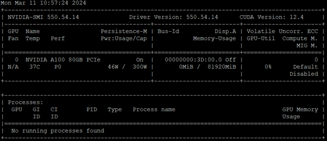 Response of the previous command:
Procedure 2. (Optional) Run a Sample “CUDA VectorAdd” GPU Application
NVAIE containers are provided on https://catalog.ngc.nvidia.com/.
Step 1. Create a cuda-vectoradd.yaml file:
apiVersion: v1
kind: Pod
metadata:
name: cuda-vectoradd
spec:
restartPolicy: OnFailure
containers:
- name: cuda-vectoradd
image: "nvcr.io/nvidia/k8s/cuda-sample:vectoradd-cuda11.7.1-ubuntu20.04"
resources:
limits:
nvidia.com/gpu: 1
Step 2. Run the pod. (The pod starts, runs the vectorAdd command, and then exits):
# kubectl apply -f cuda-vectoradd.yaml
Step 3. Check the logs from the container:
# kubectl logs pod/cuda-vectoradd
Output
# kubectl logs pod/cuda-vectoradd
[Vector addition of 50000 elements]
Copy input data from the host memory to the CUDA device
CUDA kernel launch with 196 blocks of 256 threads
Copy output data from the CUDA device to the host memory
Test PASSED
Done
Step 4. Delete the pod:
# kubectl delete -f cuda-vectoradd.yaml
For the NVIDIA AI Enterprise software stack a license server is required to manage the license keys. Please follow these steps to deploy the NVIDIA license server in the environment.
Procedure 1. Deploy NVIDIA license server
Step 1. From https://ui.licensing.nvidia.com/software, download and extract the VMware vSphere NLS License Server (DLS) OVA.
Step 2. Follow https://docs.nvidia.com/license-system/latest/nvidia-license-system-user-guide/index.html to install the DLS appliance in the FlexPod-Management cluster.
Step 3. Once the DLS instance is installed and powered on, proceed to https://docs.nvidia.com/license-system/latest/nvidia-license-system-user-guide/index.html#registering-dls-administrator-user.
Step 4. Proceed to https://docs.nvidia.com/license-system/latest/nvidia-license-system-user-guide/index.html#configuring-service-instance and work through Creating a License Server on the NVIDIA Licensing Portal (making sure to add a feature with a number of licenses to cover the number of vGPUs you plan to deploy), DLS Instance Instructions, Registering an on-Premises DLS Instance with the NVIDIA Licensing Portal, Binding a License Server to a Service Instance, and Installing a License Server on a DLS Instance.
Procedure 1. Prerequisites
The NetApp DataOps Toolkit for Kubernetes requires that Python 3.8 or above be installed on the local host. Additionally, the toolkit requires that pip for Python3 be installed on the local host. For more details regarding pip, including installation instructions, refer to the pip documentation.
Step 1. Check the installed Python version:
sle-mgmt:~ # python3 --version
Python 3.11.5
Step 2. Create a Python 3 virtual environment for the NetApp DataOps Toolkit:
sle-mgmt:~ # python3.11 -m venv ~/aidev
sle-mgmt:~ # ls ~/aidev
bin include lib lib64 pyvenv.cfg
sle-mgmt:~ # ls ~/aidev/bin
Activate.ps1 activate activate.csh activate.fish pip pip3 pip3.11 python python3 python3.11
Step 3. Use the new Python 3 virtual environment:
sle-mgmt:~ # source ~/aidev/bin/activate
(aidev) sle-mgmt:~ #
Step 4. Install the latest version of pip into this Python virtual environment:
(aidev) sle-mgmt:~ # python3 -m pip install --upgrade pip
Requirement already satisfied: pip in ./aidev/lib64/python3.11/site-packages (24.0)
Collecting pip
Obtaining dependency information for pip from https://files.pythonhosted.org/packages/8a/6a/19e9fe04fca059ccf770861c7d5721ab4c2aebc539889e97c7977528a53b/pip-24.0-py3-none-any.whl.metadata
Downloading pip-24.0-py3-none-any.whl.metadata (3.6 kB)
Downloading pip-24.0-py3-none-any.whl (2.1 MB)
━━━━━━━━━━━━━━━━━━━━━━━━━━━━━━━━━━━━━━━━ 2.1/2.1 MB 34.1 MB/s eta 0:00:00
Installing collected packages: pip
Attempting uninstall: pip
Found existing installation: pip 23.2.1
Uninstalling pip-23.2.1:
Successfully uninstalled pip-23.2.1
Step 5. To install the NetApp DataOps Toolkit for Kubernetes, run the following command:
(aidev) sle-mgmt:~ # python3 -m pip install netapp-dataops-k8s
Collecting netapp-dataops-k8s
Downloading netapp_dataops_k8s-2.5.0-py3-none-any.whl.metadata (1.8 kB)
Collecting notebook<7.0.0 (from netapp-dataops-k8s)
Downloading notebook-6.5.6-py3-none-any.whl.metadata (2.5 kB)
Collecting pandas (from netapp-dataops-k8s)
Using cached pandas-2.2.1-cp311-cp311-manylinux_2_17_x86_64.manylinux2014_x86_64.whl.metadata (19 kB) Collecting netapp-dataops-k8s
Step 6. Confirm that the toolkit installed successfully:
(aidev) sle-mgmt:~ # ls ~/aidev/bin
Activate.ps1 jsonpointer jupyter-kernelspec jupyter-notebook pip pyrsa-sign
__pycache__ jsonschema jupyter-migrate jupyter-run pip3 pyrsa-verify
activate jupyter jupyter-nbclassic jupyter-server pip3.11 python
activate.csh jupyter-bundlerextension jupyter-nbclassic-bundlerextension jupyter-serverextension pygmentize python3
activate.fish jupyter-dejavu jupyter-nbclassic-extension jupyter-troubleshoot pyrsa-decrypt python3.11
f2py jupyter-events jupyter-nbclassic-serverextension jupyter-trust pyrsa-encrypt send2trash
ipython jupyter-execute jupyter-nbconvert netapp_dataops_k8s_cli.py pyrsa-keygen tabulate
ipython3 jupyter-kernel jupyter-nbextension normalizer pyrsa-priv2pub wsdump
(aidev) sle-mgmt:~ # netapp_dataops_k8s_cli.py version
NetApp DataOps Toolkit for Kubernetes - version 2.5.0
Step 7. Now, create a test data scientist workspace using Toolkit:
netapp_dataops_k8s_cli.py create jupyterlab --workspace-name=abhinav --size=10Gi --nvidia-gpu=1 -c ontap-gold -n dataops
(aidev) cert-test:~ # netapp_dataops_k8s_cli.py create jupyterlab --workspace-name=abhinav --size=10Gi --nvidia-gpu=1 -c ontap-gold -n dataops -b
Setting workspace password (this password will be required in order to access the workspace)...
Enter password:
Verify password:
Creating persistent volume for workspace...
Creating PersistentVolumeClaim (PVC) 'ntap-dsutil-jupyterlab-abhinav' in namespace 'dataops'.
PersistentVolumeClaim (PVC) 'ntap-dsutil-jupyterlab-abhinav' created. Waiting for Kubernetes to bind volume to PVC.
Volume successfully created and bound to PersistentVolumeClaim (PVC) 'ntap-dsutil-jupyterlab-abhinav' in namespace 'dataops'.
Creating Service 'ntap-dsutil-jupyterlab-abhinav' in namespace 'dataops'.
Service successfully created.
Creating Deployment 'ntap-dsutil-jupyterlab-abhinav' in namespace 'dataops'.
Deployment 'ntap-dsutil-jupyterlab-abhinav' created.
Waiting for Deployment 'ntap-dsutil-jupyterlab-abhinav' to reach Ready state.
Deployment successfully created.
Workspace successfully created.
To access workspace, navigate to http://10.104.3.91:31526
Step 8. Access the workspace, using the URL http://10.104.3.91:31526 and enter the password configured during workspace creation.
Note: In the later section, for validating AI use cases, Jupyter Notebook will be deployed using NetApp DataOps toolkit.
This chapter contains the following:
· Generative Inferencing AI Model Deployment and Results
Generative Inferencing AI Model Deployment and Results
Stable Diffusion
Stable Diffusion is an open-source image generation model that allows to generate images using a simple text prompt.
Stable Diffusion is a text-to-image latent diffusion model created by the researchers and engineers from CompVis, Stability AI and LAION. It is trained on 512x512 images from a subset of the LAION-5B database. LAION-5B is the largest, freely accessible multi-modal dataset that currently exists.
Stable Diffusion performs the following image related tasks:
· Text-to-Image: Create an image from a text prompt.
· Image-to-Image: Create an image from an existing image and a text prompt.
· Depth-Guided Diffusion: Modify an existing image with its depth map and a text prompt.
· Instruct Pix2Pix: Modify an existing image with a text prompt.
· Stable UnCLIP Variations: Create different versions of an image with a text prompt.
· Image Upscaling: Create a high-resolution image from an existing image with a text prompt.
· Diffusion Inpainting: Modify specific areas of an existing image with an image mask and a text prompt.
| Component |
Version |
| Stable Diffusion 1.4 |
|
| Stable Diffusion 1.5 |
|
| Stable Diffusion 2 |
|
| Stable Diffusion 2.1 |
|
| Stable Diffusion XL |
https://huggingface.co/stabilityai/stable-diffusion-xl-base-1.0 |
Procedure 1. Create a workspace
Step 1. Create a Jupyter notebook using NetApp DataOps toolkit:
netapp_dataops_k8s_cli.py create jupyterlab --workspace-name=genai -c ontap-gold --size=100Gi --nvidia-gpu=1 -n dataops -i nvcr.io/nvidia/pytorch:23.10-py3
Note: The workspace creates a pod with pytorch image and will use ontap-gold storage class for the persistent volume claim (PVC), 1 GPU will be assigned to this workspace.
Step 2. Run the following code on the notebook:
pip install --upgrade diffusers transformers scipy
import torch
from diffusers import StableDiffusionPipeline
model_id = "CompVis/stable-diffusion-v1-4"
device = "cuda"
pipe = StableDiffusionPipeline.from_pretrained(model_id, torch_dtype=torch.float16)
pipe = pipe.to(device)
prompt = "a small cabin on top of a snowy mountain in the style of Disney, artstation"
image = pipe(prompt).images[0]
image.save("cabin_snowy_disney.png")
Figure 5. Image generated by Stable Diffusion 1.4

The inferencing was run with one A100 GPU, 10% of tensor core utilization with 3.6 Gigabyte of memory utilization:
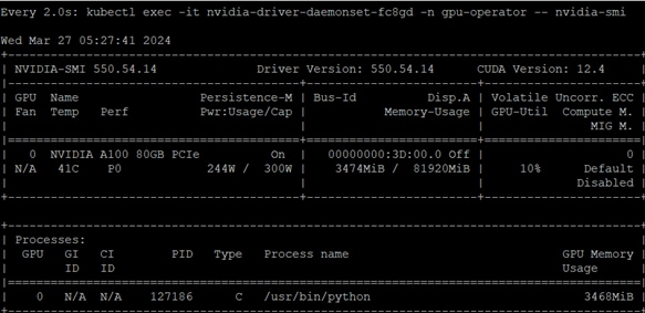
Python script for Stable Diffusion XL1.0:
import torch
from diffusers import StableDiffusionXLPipeline
model_id = "stabilityai/stable-diffusion-xl-base-1.0"
device = "cuda"
pipe = DiffusionPipeline.from_pretrained("stabilityai/stable-diffusion-xl-base-1.0", torch_dtype=torch.float16, use_safetensors=True, variant="fp16")
pipe = pipe.to(device)
prompt = "A ninja turtle jumping from a mountain in lightning rain, detailed, 8k resolution"
image = pipe(prompt).images[0]
image.save("turtle.png")
Figure 6. Image generated by Stable Diffusion XL 1.0

The inferencing was run with one A100 GPU, 48% of tensor core utilization with 14.7 Gigabyte of memory utilization.
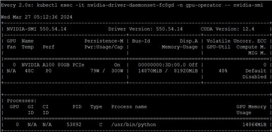
Dreamlike Photoreal 2.0
Dreamlike Photoreal 2.0 is a photorealistic model based on Stable Diffusion 1.5, made by dreamlike.art. The same inferencing method was used as Stable Diffusion.
Hugging face: https://huggingface.co/dreamlike-art/dreamlike-photoreal-2.0
Figure 7 is generated by the prompt “photo, a church in the middle of a field of crops, bright cinematic lighting, gopro, fisheye lens.”
Figure 7. Dreamlike photoreal 2.0 image

The inferencing was run with one A100 GPU, 98% of tensor core utilization with 7.7 Gigabyte of memory utilization.
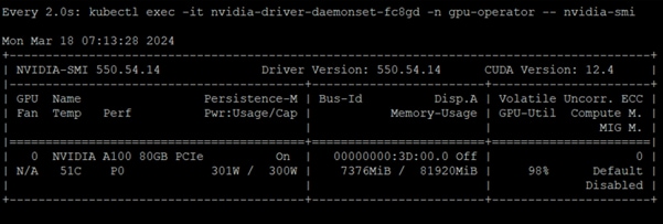
Openjourney
Openjourney is an open-source Stable Diffusion fine-tuned model on Midjourney images. Model used in this validation is prompthero/openjourney.
Figure 8 is generated for the prompt “racing series of different cars with different colors and shapes, mdjrny-v4 style”.
Figure 8. Openjourney generated image

The inferencing was run with one A100 GPU. 97% of tensor core utilization with 3.6 Gigabyte of memory was consumed.
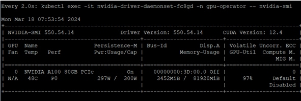
Hotshot-XL
Hotshot-XL is an AI text-to-GIF model trained to work alongside Stable Diffusion XL. Hotshot-XL was trained to generate 1 second GIFs at 8 FPS.
Hotshot-XL can generate GIFs with any fine-tuned SDXL model. It is possible to make GIFs with any existing or newly fine-tuned SDXL model.
Git repo: https://github.com/hotshotco/Hotshot-XL
Hugging face: https://huggingface.co/hotshotco/Hotshot-XL
Procedure 1. Create a new Jupyter notebook
Step 1. Use the DataOps toolkit and launch the terminal to run the commands:
git clone https://github.com/hotshotco/Hotshot-XL
cd Hotshot-XL
Step 2. Environment Setup:
pip install virtualenv --upgrade
virtualenv -p $(which python3) venv
source venv/bin/activate
pip install -r requirements.txt
Step 3. Install git-lfs:
curl -s https://packagecloud.io/install/repositories/github/git-lfs/script.deb.sh | bash
apt-get install git-lfs
Step 4. Download the Hotshot-XL Weights:
# Make sure you have git-lfs installed (https://git-lfs.com)
git lfs install
git clone https://huggingface.co/hotshotco/Hotshot-XL
Step 5. Download our fine-tuned SDXL model (or BYOSDXL):
# Make sure you have git-lfs installed (https://git-lfs.com)
git lfs install
git clone https://huggingface.co/hotshotco/SDXL-512
Step 6. Text-to-GIF:
python inference.py \
--prompt="a bulldog in the captains chair of a spaceship, hd, high quality" \
--output="output.gif"
Figure 9. A GIF image is generated by the text prompt

The inferencing was run with one A100 GPU. 99% of tensor core utilization with 12.7 Gigabyte of memory was consumed:
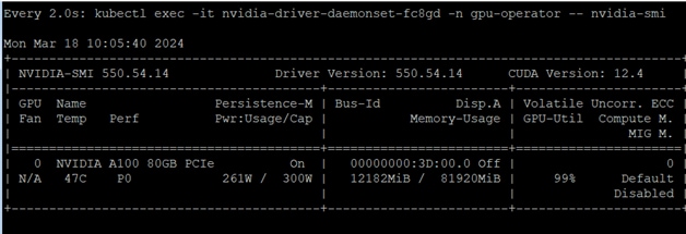
Text Generation Inference
Text Generation Inference (TGI) is a toolkit for deploying and serving Large Language Models (LLMs). TGI enables high-performance text generation for the most popular open-source LLMs, including Llama, Falcon, StarCoder, BLOOM, GPT-NeoX, and T5.
Figure 10. TGI Model Representation
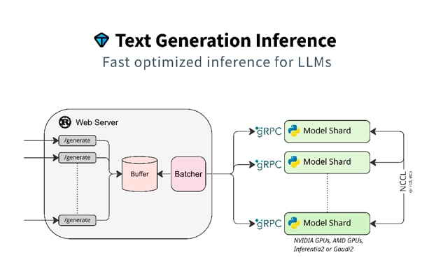
A list of supported models can be found here.
| Model |
Download Location |
| BLOOM-7B |
|
| Google FLAN-T5 XXL |
|
| Mistral-7B-Instruct-v0.2 |
|
| MPT-30B |
|
| FALCON-7B |
Step 7. Create a PVC for the container.
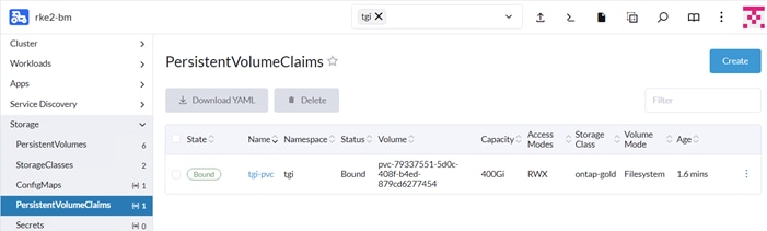
Step 8. Deploy tgi container from the below yaml file:
apiVersion: apps/v1
kind: Deployment
metadata:
name: tgi-deployment
namespace: tgi
spec:
strategy:
type: Recreate
replicas: 1
selector:
matchLabels:
app: tgi
template:
metadata:
labels:
app: tgi
name: tgi-pod
spec:
volumes:
- name: tgi
persistentVolumeClaim:
claimName: tgi-pvc
- name: shm
emptyDir:
medium: Memory
sizeLimit: 10Gi
restartPolicy: Always
containers:
- name: tgi-container
image: ghcr.io/huggingface/text-generation-inference
command: [ "/bin/bash", "-c", "--" ]
args: [ "while true; do sleep 30; done;" ]
volumeMounts:
- name: tgi
mountPath: /data
- name: shm
mountPath: /dev/shm
resources:
limits:
nvidia.com/gpu: 1
Step 9. Apply the file to create service:
kind: Service
apiVersion: v1
metadata:
name: tgi-svc
namespace: tgi
spec:
type: NodePort
selector:
app: tgi
ports:
- protocol: TCP
nodePort:
port: 8080
targetPort: 8080
Step 10. Run the command from the management host for inferencing:
sle-mgmt:~ # curl 10.104.3.91:31349/generate -X POST -d '{"inputs":"What is Deep Learning?","parameters":{"max_new_tokens":20}}' -H 'Content-Type: application/json'
{"generated_text":" Deep learning is a branch of machine learning that uses deep neural networks to learn complex tasks. Deep learning"}(aidev)
Results
The TGI container contains a python benchmark script that was run for each of the models utilizing one GPU with results in the following table. Each model was first loaded from the container with:
text-generation-launcher --model-id bigscience/bloom-7b1 --json-output --trust-remote-code --hostname 0.0.0.0 -p 8080
From another window in the container:
text-generation-benchmark --tokenizer-name=bigscience/bloom-7b1 --batch-size=1 --runs=100 --warmups=10
Table 12. TGI Benchmark Results
| Model |
Batch Size |
Prefill Latency (ms) |
Decode Token Latency (ms)
|
Decode Total Latency (ms)
|
Prefill Throughput (token/s) |
Decode Throughput (token/s)
|
| BLOOM-7B |
1 |
13.39 |
12.79 |
100.25 |
74.71 |
69.83 |
| 2 |
14.22 |
14.31 |
90.83 |
140.7 |
152.58 |
|
| 4 |
15.75 |
13.66 |
95.65 |
256.57 |
292.82 |
|
| 8 |
23.42 |
15.5 |
108.51 |
354.22 |
516.49 |
|
| FLAN-T5 XXL |
1 |
26.52 |
16.04 |
112.3 |
37.75 |
62.42 |
| 2 |
28.79 |
16.84 |
117.9 |
69.74 |
118.98 |
|
| 4 |
31.01 |
17.13 |
119.93 |
131.66 |
233.62 |
|
| 8 |
47.53 |
21.24 |
148.65 |
175.9 |
377.19 |
|
| Mistral-7B-Instruct-v0.2 |
1 |
13.09 |
11.89 |
83.21 |
76.41 |
84.15 |
| 2 |
13.96 |
12.17 |
85.18 |
143.82 |
164.46 |
|
| 4 |
14.88 |
12.31 |
86.19 |
269.13 |
324.94 |
|
| 8 |
17.45 |
12.81 |
89.69 |
460.92 |
24.83 |
|
| MPT-30B |
1 |
12.68 |
11.31 |
79.19 |
78.93 |
88.4 |
| 2 |
12.92 |
11.46 |
80.22 |
155.12 |
174.54 |
|
| 4 |
13.57 |
11.63 |
81.43 |
295 |
343.91 |
|
| 8 |
16.06 |
12.05 |
84.32 |
483.22 |
664.39 |
|
| FALCON-7B |
1 |
12.56 |
11.28 |
78.98 |
79.64 |
88.64 |
| 2 |
12.77 |
11.44 |
80.12 |
156.7 |
174.75 |
|
| 4 |
13.74 |
11.71 |
81.96 |
291.09 |
341.66 |
|
| 8 |
16.59 |
12.12 |
84.84 |
483.17 |
660.35 |
NVIDIA NeMo Framework
NVIDIA NeMo™ Framework is a development platform for building custom generative AI models. The framework supports custom models for language (LLMs), multimodal, computer vision (CV), automatic speech recognition (ASR), natural language processing (NLP), and text to speech (TTS). NVIDIA NeMo framework is a scalable and cloud-native generative AI framework built for researchers and developers working on Large Language Models, Multimodal, and Speech AI (Automatic Speech Recognition and Text-to-Speech). It enables users to efficiently create, customize, and deploy new generative AI models by leveraging existing code and pretrained model checkpoints.
Note: NVIDIA NeMo inferencing, which uses Triton Inferencing Server, was implemented along with three AI models.
| Model |
Download Location |
Processing |
| Llama-2-7B-Chat |
Yes |
|
| Llama-2-13B-Chat |
Yes |
|
| Nemotron-3-8B-QA-4K |
NVIDIA NGC Private Registry |
None |
Procedure 1. Deployment
To deploy Nemo framework container for hf to nemo conversion, a nemo namespace was created. NGC secret to pull images from NVIDIA registry was created.
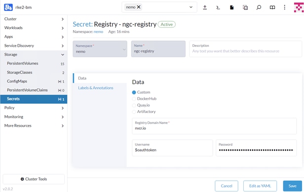
Step 1. Create a PVC in the same namespace.
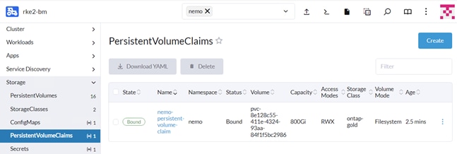
Note: The PVC needs to be configured with access mode ReadWriteMany as it will be shared across multiple containers.
Step 2. Deploy Nemo framework container from the below yaml file. This container is used to convert various models from .hf to .nemo.
apiVersion: apps/v1
kind: Deployment
metadata:
name: nemo-framework-training-deployment
namespace: nemo
spec:
strategy:
type: Recreate
# Replicas controls the number of instances of the Pod to maintain running at all times
replicas: 1
selector:
matchLabels:
app: nemo-framework-training
template:
metadata:
labels:
app: nemo-framework-training
name: nemo-framework-training-pod
spec:
imagePullSecrets:
- name: ngc-registry
volumes:
- name: model-repository
persistentVolumeClaim:
claimName: nemo-persistent-volume-claim
- name: dshm
emptyDir:
medium: Memory
sizeLimit: 100Gi
containers:
- name: nemo-framework-training-container
image: nvcr.io/nvidia/nemo:24.01.01.framework
command: [ "/bin/bash", "-c", "--" ]
args: [ "while true; do sleep 30; done;" ]
volumeMounts:
- name: model-repository
mountPath: /opt/checkpoints
- mountPath: /dev/shm
name: dshm
ports:
- name: nemo
containerPort: 8000
resources:
limits:
nvidia.com/gpu: 1
Step 3. Download Llama-2 models from hugging face. We downloaded and converted Llama-2-7b-chat and Llama-2-13b-chat models.
# cd /opt/checkpoints
# mkdir Llama-2-13b-chat
# huggingface-cli download meta-llama/Llama-2-13b-chat-hf --local-dir Llama-2-13b-chat
# ls Llama-2-13b-chat/
LICENSE.txt config.json model-00003-of-00003.safetensors pytorch_model-00003-of-00003.bin tokenizer.model
README.md generation_config.json model.safetensors.index.json pytorch_model.bin.index.json tokenizer_config.json
Responsible-Use-Guide.pdf model-00001-of-00003.safetensors pytorch_model-00001-of-00003.bin special_tokens_map.json
USE_POLICY.md model-00002-of-00003.safetensors pytorch_model-00002-of-00003.bin tokenizer.json
# python /opt/NeMo/scripts/nlp_language_modeling/convert_hf_llama_to_nemo.py --in-file=./Llama-2-13b-chat/ --out-file=Llama2-13b-chat.nemo
Note: You need to login to hugging face cli by providing the access token to download Llama-2 models:
root@nemo-framework-training-deployment-bb4dc6f6-dzw5x:/opt/checkpoints# ls
Llama-2-13b-chat Llama-2-13b-chat.nemo Llama2-7b-chat Llama2-7b-chat.nemo
Step 4. Deploy Nemo Inference container using the deployment file:
apiVersion: apps/v1
kind: Deployment
metadata:
name: nemo-framework-inference-deployment
namespace: nemo
spec:
strategy:
type: Recreate
# Replicas controls the number of instances of the Pod to maintain running at all times
replicas: 1
selector:
matchLabels:
app: nemo-framework-inference
template:
metadata:
labels:
app: nemo-framework-inference
name: nemo-framework-inference-pod
spec:
imagePullSecrets:
- name: ngc-registry
volumes:
- name: model-repository
persistentVolumeClaim:
claimName: nemo-persistent-volume-claim
- name: dshm
emptyDir:
medium: Memory
sizeLimit: 100Gi
containers:
- name: nemo-framework-inference-container
image: nvcr.io/ea-bignlp/ga-participants/nemofw-inference:23.10
command: [ "/bin/bash", "-c", "--" ]
args: [ "while true; do sleep 30; done;" ]
volumeMounts:
- name: model-repository
mountPath: /opt/checkpoints
- mountPath: /dev/shm
name: dshm
ports:
- name: nemo
containerPort: 8000
resources:
limits:
nvidia.com/gpu: 1
Step 5. To run NeMo Triton Inferencing server with a model, such as Llama-2-7B, run the following from the /opt/NeMo directory within the container:
python scripts/deploy/deploy_triton.py --nemo_checkpoint /opt/checkpoints/Llama2-7b-chat.nemo --model_type="llama" --triton_model_name Llama-2-7b-chat-hf --triton_model_repository /opt/checkpoints/trt_llm_model_dir_7b --triton_http_address 0.0.0.0 --triton_port 8000 --num_gpus 2 --max_input_len 3072 --max_output_len 1024 --max_batch_size 8 &
The following message displays once the model is loaded:
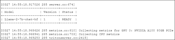
Step 6. Place the example in a python file and run a test python script:
from nemo.deploy import NemoQuery
nq = NemoQuery(url="localhost:8000", model_name="Llama-2-7b-chat-hf"
output = nq.query_llm(prompts=["What is the capital of Argentina?"], max_output_token=1024, top_k=1, top_p=0.0, temperature=1.0)
print(output)
Output

Results
The NeMo Inference container contains a python benchmark script that was run for both models utilizing one GPU with results in the following table. To launch the benchmark script, run the following from the /opt/NeMo directory within the container.
python scripts/deploy/benchmark.py --nemo_checkpoint /opt/checkpoints/Llama2-7b-chat.nemo --model_type="llama" --triton_model_name Llama-2-7b-chat-hf -tlf /opt/checkpoints/trt_llm_model_dir_7b -ng 1 -mil 2048 -mol 300 -mbs 10 -nr 50 --out_jsonl="/opt/checkpoints/Llama2-7b-chat.nemo.json"
Note: Delete the trt_llm_model_dir directory between benchmark runs; each run will create a new directory with the provided name in the script.
Step 7. For Nemotron-3-8B-QA-4k, run the following:
# ngc config set
Enter API key [no-apikey]. Choices: [<VALID_APIKEY>, 'no-apikey']:
Enter CLI output format type [ascii]. Choices: ['ascii', 'csv', 'json']:
Enter org [xxxxxxxxx]. Choices:
Enter team [xx-team]. Choices:
Validating configuration...
Successfully validated configuration.
Saving configuration...
Successfully saved NGC configuration to /root/.ngc/config
# ngc registry model download-version "dztrnjtldi02/nemotron-3-8b-qa-4k:1.0"
![]()
Step 8. To run NeMo Triton Inferencing server with Nemotron-3-8B-QA-4k, run the following command from /opt/nemo directory within the container:
python scripts/deploy/deploy_triton.py --nemo_checkpoint /opt/checkpoints/nemotron-3-8b-qa-4k_v1.0/Nemotron-3-8B-QA-4k.nemo --model_type="gptnext" --triton_model_name Nemotron-3-8B-QA-4k --triton_model_repository /opt/checkpoints/trt_llm_model_dir_8b --triton_http_address 0.0.0.0 --triton_port 8000 --num_gpus 1 --max_input_len 3072 --max_output_len 1024 --max_batch_size 8 &
The following message displays once Nemotron-3-8B-QA-4k model is loaded:
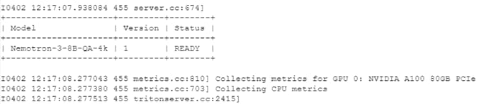
Step 9. Run the benchmark script:
python scripts/deploy/benchmark.py --nemo_checkpoint /opt/checkpoints/nemotron-3-8b-qa-4k_v1.0/Nemotron-3-8B-QA-4k.nemo --model_type="gptnext" --triton_model_name Nemotron-3-8B-QA-4k -tlf /opt/checkpoints/trt_llm_model_dir_8b -ng 1 -mil 2048 -mol 300 -mbs 10 -nr 50 --out_jsonl="/opt/checkpoints/Nemotron-3-8B-QA-4k.nemo.json"
Note: For the NeMo models, the model_type is “gptnext.”
Table 14. NeMo Framework Benchmark Results with 1 GPU: Input Tokens Length: 128 and Output Tokens Length: 20
| Model |
Batch Size |
Average Latency (ms) |
Average Throughput (Token/s) |
| Llama-2-7B-Chat |
1 |
151.628 |
6.479 |
| 2 |
153.696 |
12.704 |
|
| 4 |
180.195 |
22.163 |
|
| 8 |
228.901 |
34.95 |
|
| Llama-2-13B-Chat |
1 |
434.628 |
2.302 |
| 2 |
457.754 |
4.369 |
|
| 4 |
502.648 |
7.958 |
|
| 8 |
597.883 |
13.381 |
|
| Nemotron-3-8B-QA |
1 |
267.946 |
3.732 |
| 2 |
285.067 |
7.016 |
|
| 4 |
297.743 |
13.434 |
|
| 8 |
347.773 |
23.004 |
Table 15. NeMo Framework Benchmark Results with 1 GPU: Input Tokens Length: 2048 and Output Tokens Length: 300
| Model |
Batch Size |
Average Latency (ms) |
Average Throughput (Token/s) |
| Llama-2-7B-Chat |
1 |
4046.969 |
0.247 |
| 2 |
4281.757 |
0.467 |
|
| 4 |
5304.155 |
0.754 |
|
| 8 |
6860.297 |
1.166 |
|
| Llama-2-13B-Chat |
1 |
7020.491 |
0.142 |
| 2 |
7582.776 |
0.264 |
|
| 4 |
9031.917 |
0.443 |
|
| 8 |
11606.005 |
0.689 |
|
| Nemotron-3-8B-QA |
1 |
4254.244 |
0.235 |
| 2 |
4486.722 |
0.446 |
|
| 4 |
5465.896 |
0.732 |
|
| 8 |
6960.6 |
1.149 |
While running the benchmark for Llama-2-7b-chat with one A100 GPU, 94% of tensor core utilization with 39.1 Gigabyte of memory was consumed:
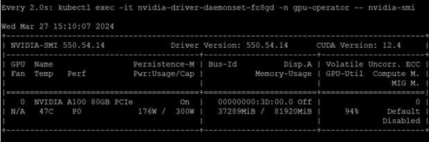
Storage performance while running benchmark script:
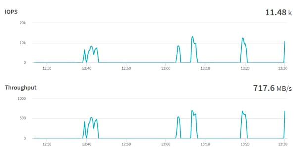
While running the benchmark for Nemotron-3-8B-QA with one A100 GPU, 91% of tensor core utilization with 83.3 Gigabyte of memory was consumed:
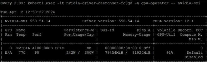
Retrieval-Augmented Generation (RAG) on NVIDIA L40S GPU
Retrieval-augmented generation (RAG) is a software architecture that combines the capabilities of large language models (LLMs), renowned for their general knowledge of the world, with information sources specific to a business, such as documents, SQL databases, and internal business applications. RAG enhances the accuracy and relevance of the LLM’s responses. RAG uses vector database technology to store up-to-date information that’s retrieved using semantic searches and added to the context window of the prompt, along with other helpful information, to enable the LLM to formulate the best possible, up-to-date response. This architecture has become famous for many use cases, including its ability to offer detailed, relevant answers by integrating the best of both worlds—knowledge from LLMs and proprietary business data.
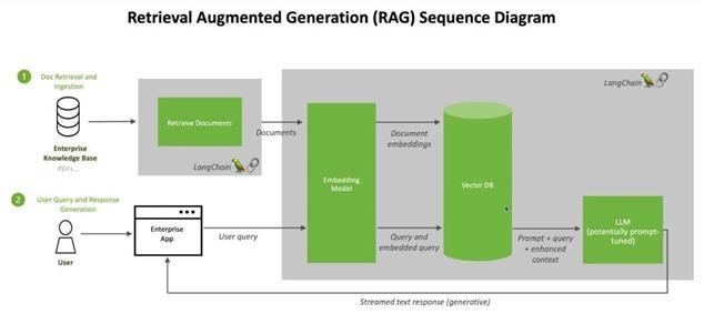
Step 1. Deploy a Jupyter notebook using NetApp DataOps toolkit:
netapp_dataops_k8s_cli.py create jupyterlab --workspace-name=rag -c ontap-nas-flxgrp --size=400Gi --nvidia-gpu=1 -n dataops -i nvcr.io/nvidia/pytorch:23.10-py3
Step 2. Launch the notebook and install the libraries:
!pip install langchain transformers accelerate tiktoken openai gradio torch accelerate \
safetensors sentence-transformers faiss-gpu bitsandbytes pypdf typing-extensions
!pip uninstall typing-extensions --yes
!pip install typing-extensions
!pip install PyPDF2
Step 3. Import the libraries:
import torch
import PyPDF2 # pdf reader
import time
from pypdf import PdfReader
from io import BytesIO
from langchain.prompts import PromptTemplate # for custom prompt specification
from langchain.text_splitter import RecursiveCharacterTextSplitter # splitter for chunks
from langchain.embeddings import HuggingFaceEmbeddings # embeddings
from langchain.vectorstores import FAISS # vector store database
from langchain.chains import RetrievalQA # qa and retriever chain
from langchain.memory import ConversationBufferMemory # for model's memoy on past conversations
from langchain.document_loaders import PyPDFDirectoryLoader # loader fo files from firectory
from langchain.llms.huggingface_pipeline import HuggingFacePipeline # pipeline
from transformers import AutoModelForCausalLM, AutoTokenizer, pipeline, BitsAndBytesConfig
Step 4. For the embedding, we used sentence-transformers/all-mpnet-base-v2:
CHUNK_SIZE = 1000
# Using HuggingFaceEmbeddings with the chosen embedding model
embeddings = HuggingFaceEmbeddings(
model_name="sentence-transformers/all-mpnet-base-v2",model_kwargs = {"device": "cuda"})
# transformer model configuration
# this massively model's precision for memory effieciency
# The models accuacy is reduced.
quant_config = BitsAndBytesConfig(
load_in_4bit=True,
bnb_4bit_use_double_quant=True,
bnb_4bit_quant_type="nf4",
bnb_4bit_compute_dtype=torch.bfloat16
)
tensor_1 = torch.rand (4,4)
Step 5. Load Deci/DeciLM-7B-instruct model and create pipeline:
model_id = "Deci/DeciLM-7B-instruct" # model repo id
device = 'cuda' # Run on gpu if available else run on cpu
#
tokenizer = AutoTokenizer.from_pretrained(model_id)
model = AutoModelForCausalLM.from_pretrained(model_id,
trust_remote_code=True,
device_map = "auto",
quantization_config=quant_config)
# create a pipeline
pipe = pipeline("text-generation",
model=model,
tokenizer=tokenizer,
return_full_text = True,
max_new_tokens=200,
repetition_penalty = 1.1,
num_beams=5,
no_repeat_ngram_size=4,
early_stopping=True)
llm = HuggingFacePipeline(pipeline=pipe))
Note: We created a folder in Jupyter notebook with the name cvd and have uploaded latest CVDs.
Step 6. Provide the path of the folder:
pdf_paths = "cvd/"
loader = PyPDFDirectoryLoader(
path= pdf_paths,
glob="*.pdf"
)
documents=loader.load()
print(len(documents))
documents[0] # display four documents
Step 7. Text splitter with chunk size:
text_splitter = RecursiveCharacterTextSplitter(chunk_size=CHUNK_SIZE,
chunk_overlap=100)
splits = text_splitter.split_documents(documents)
# length of all splits
print(f"We have, {len(splits)} chunks in memory"))
Step 8. A database is required to store embeddings and to efficiently search for them. Therefore, for storage and searching purposes, we need vector stores. There are many vector stores integrated with LangChain, we have used Facebook AI Similarity Search (“FAISS”) vector store.
vectorstore_db = FAISS.from_documents(splits, embeddings) # create vector db for similarity
Step 9. Performs a similarity check and returns the top K embeddings that are similar to the question’s embeddings:
retriever = vectorstore_db.as_retriever(search_type="similarity", search_kwargs={"k": 6})
Step 10. Once the data is in the database, the LLM model is prepared, and the pipeline is created, then we need to retrieve the data. A retriever is an interface that returns documents from the query:
retrieved_relevant_docs = retriever.get_relevant_documents(
"Based on the flexpod vcf pdf, what is workload domain?"
)
print(f"Retrieved documents: {len(retrieved_relevant_docs)}")
f"Page content of first document:\n {retrieved_relevant_docs[0].page_content}"
Output
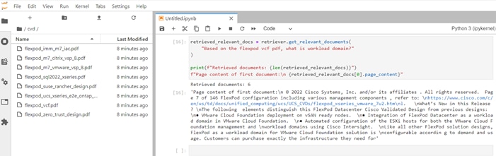
Step 11. Create a custom template, prompt template and qa chain:
custom_prompt_template = """You are an assistant for question-answering tasks. Use the following pieces of retrieved context and answer the question at the end.
If you don't know the answer just say you d not know an do not try to make up the answer nor try to use outside souces to answer. Keep the answer as concise as possible.
Context= {context}
History = {history}
Question= {question}
Helpful Answer:
"""
prompt = PromptTemplate(template=custom_prompt_template,
input_variables=["question", "context", "history"])
qa_chain_with_memory = RetrievalQA.from_chain_type(llm=llm, chain_type='stuff',
retriever = vectorstore_db.as_retriever(),
return_source_documents = True,
chain_type_kwargs = {"verbose": True,
"prompt": prompt,
"memory": ConversationBufferMemory(
input_key="question",
memory_key="history",
return_messages=True)})
Step 12. Run the query:
query = "Explain me about NetApp DataOps toolkit?"
qa_chain_with_memory({"query": query })
Output
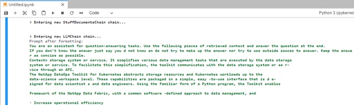
While running the question and answering with one L40S GPU, 94% of tensor core utilization with 36.6 Gigabyte of memory was consumed:
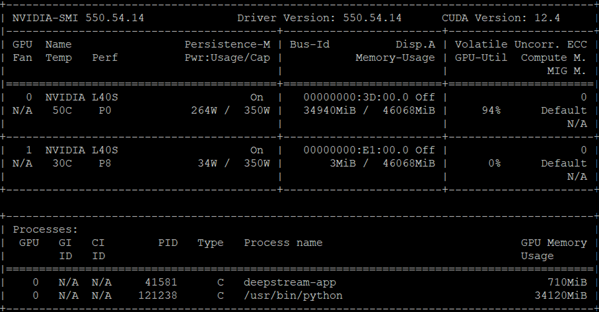
Resnet32
Deep learning has evolved a lot in recent years and we all are excited to build deeper architecture networks to gain more accuracies for our models. These techniques are widely tried for Image related works like classification, clustering, or synthesis.
Resnet models were proposed in “Deep Residual Learning for Image Recognition.” Restnet32 is pre-trained on the ImageNet dataset which contains 100,000+ images across 200 different classes. Here we have the 5 versions of Resnet models, which contain 18, 34, 50, 101, 152 layers, respectively. In this document, we will look at one of the healthcare use case (Diabetic Retinopathy Detection) of ResNet-32 model using the Tensor flow framework in Python.
Sample training and test dataset: https://www.kaggle.com/code/balajiai/diabetic-retinopathy-detection-using-pytorch/input
Training and validation: https://www.kaggle.com/code/balajiai/diabetic-retinopathy-detection-using-pytorch/notebook
Step 1. Deploy a Jupyter notebook with the help of DataOps toolkit:
netapp_dataops_k8s_cli.py create jupyterlab --workspace-name=resnet -c ontap-gold --size=100Gi --nvidia-gpu=1 -n dataops -i nvcr.io/nvidia/pytorch:23.10-py3
91% accuracy was achieved on the training set and 80% accuracy on validation set. The model was optimized using 60 Epochs.
Figure 11. Training and validation loss against epochs
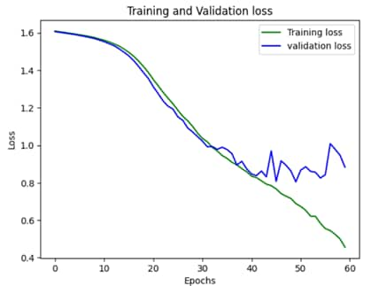
The inferencing was run with one A100 GPU, 48% of tensor core utilization with 24.3 Gigabyte of memory was consumed in each epoch:
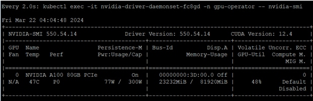
Llama 2
Llama 2 is a pretrained and fine-tuned text generation models based on autoregressive, transformer architecture. Llama 2 comes with 3 models with 7 billion, 13 billion and 70 billion parameters. Llama 2 is an opensource model which is at par in performance with ChatGPT. In this validation we have used Llama-2-7b-chat model. PyTorch was used to run the model which was created by NetApp DataOps toolkit.
Procedure 1. Deployment
Step 1. Build a modified PyTorch NGC container using podman and push it to a container registry:
Sle-mgmt :~/pytorch # cat Dockerfile
FROM nvcr.io/nvidia/pytorch:23.10-py3
#Additional packages required to run the application can be installed
RUN apt-get update && apt-get install -y \
apache2 \
curl \
git \
python3-pip
RUN git clone https://github.com/facebookresearch/llama.git
RUN pip install -r /workspace/llama/requirements.txt
Step 2. To prepare to download the Llama 2 models, go to: https://llama.meta.com/llama-downloads and fill out the form. Download instruction will be shared via email. Create a “llama-2” namespace in Rancher for RK2E-BM cluster and create a 400GB PVC using FlexGroup storage class.
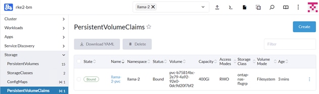
Step 3. Deploy a TGI container using the deployment file:
apiVersion: apps/v1
kind: Deployment
metadata:
name: llama-2-deployment
namespace: llama-2
spec:
replicas: 1
selector:
matchLabels:
app: llama-2
template:
metadata:
labels:
app: llama-2
name: llama-2-pod
spec:
#NetApp Astra Trident PVC to store the model weights and tokenizer
volumes:
- name: model-repository
persistentVolumeClaim:
claimName: llama-2-pvc
containers:
- name: llama-2-container
image: docker.io/********/pytorch
command: [ "/bin/bash", "-c", "--" ]
args: [ "while true; do sleep 30; done;" ]
resources:
limits:
nvidia.com/gpu: 1
volumeMounts:
- name: model-repository
mountPath: /model_repository
Step 4. After the pod is running, login to container shell from the Rancher and execute the below commands to download the model.
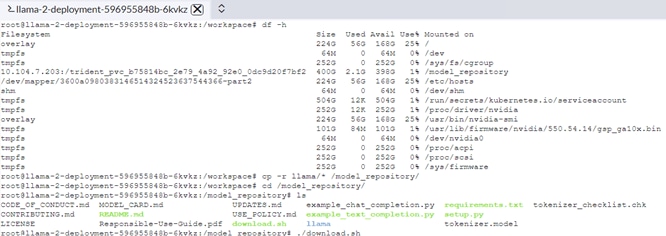
Enter the URL from email:
Enter the list of models to download without spaces (7B,13B,70B,7B-chat,13B-chat,70B-chat), or press Enter for all: 7B-chat
root@llama-2-deployment-596955848b-9nfk5:/model_repository# time torchrun --nproc_per_node 1 example_chat_completion.py --ckpt_dir llama-2-7b-chat/ --tokenizer_path tokenizer.model --max_seq_len 512 --max_batch_size 6
> initializing model parallel with size 1
> initializing ddp with size 1
> initializing pipeline with size 1
/usr/local/lib/python3.10/dist-packages/torch/__init__.py:613: UserWarning: torch.set_default_tensor_type() is deprecated as of PyTorch 2.1, please use torch.set_default_dtype() and torch.set_default_device() as alternatives. (Triggered internally at /opt/pytorch/pytorch/torch/csrc/tensor/python_tensor.cpp:451.)
_C._set_default_tensor_type(t)
Loaded in 4.72 seconds
Result
When running the commands, the Llama-2-7B-Chat model with one GPU loaded in 4.72 seconds and ran in 21.861 seconds.
This solution design is based on Cisco FlexPod for RKE2 running on SUSE Linux Enterprise 15 for production-ready deployment processes with latest best practices, a stable, highly available environment to run enterprise-grade application containers and AL/ML workloads.
FlexPod is the optimal shared infrastructure foundation to deploy a variety of IT workloads. It is built on leading computing, networking, storage, and infrastructure software components. The integration of FlexPod converged infrastructure with SUSE RKE2 and Rancher provides a very good starting point for enterprise IT to make in-roads into DevOps and CI/CD model for application development to address immediate business needs and reducing time to market. Enterprises can accelerate on the path to an enterprise-grade Kubernetes solution with SUSE RKE2 running on Cisco FlexPod infrastructure.
In this solution, we tested various Generative AI use cases and provided the results of the various tests for different models. Running containerized application along with Generative AI workloads on FlexPod can give maximum ROI.
Ulrich Kleidon, Principal Engineer, UCS Solutions, Cisco Systems
Ulrich Kleidon is a Principal Engineer for Cisco's Unified Computing System (Cisco UCS) solutions team and a lead architect for solutions around converged infrastructure stacks, enterprise applications, data protection, software-defined storage, and Hybrid-Cloud. He has over 25 years of experience designing, implementing, and operating solutions in the data center.
Abhinav Singh, Sr. Technical Marketing Engineer, Hybrid Cloud Infra & OEM Solutions, NetApp
Abhinav Singh is a Senior Technical Marketing Engineer for FlexPod solutions team and has more than 14 years of experience in Data Center infrastructure solutions which includes On-prem and Hybrid cloud space. He focuses on the designing, validating, implementing, and supporting converged infrastructure and hybrid cloud infrastructure solutions. Abhinav holds a bachelor's degree in electrical and electronics.
Acknowledgements
Appendix
This appendix contains the following:
· Compute
· NVIDIA
· Network
· Storage
Cisco Intersight SaaS Platform
Cisco Intersight SaaS platform maintains your configurations online. No separate backup was created for UCS configuration. If you are using an Intersight Private Virtual Appliance (PVA), ensure that the NetApp SnapCenter Plugin for VMware vSphere is creating periodic backups of this appliance.
Cisco Nexus Backups
The configuration of the Cisco Nexus 9000 switches can be backed up manually at any time with the copy command, but automated backups can be enabled using the NX-OS feature scheduler.
An example of setting up automated configuration backups of one of the NX-OS switches is shown below:
feature scheduler
scheduler logfile size 1024
scheduler job name backup-cfg
copy running-config tftp://<server-ip>/$(SWITCHNAME)-cfg.$(TIMESTAMP) vrf management
exit
scheduler schedule name daily
job name backup-cfg
time daily 2:00
end
Note: Using “vrf management” in the copy command is only needed when Mgmt0 interface is part of VRF management.
Verify the scheduler job has been correctly setup using following command(s):
show scheduler job
Job Name: backup-cfg
--------------------
copy running-config tftp://10.1.156.150/$(SWITCHNAME)-cfg.$(TIMESTAMP) vrf management
==============================================================================
show scheduler schedule
Schedule Name : daily
---------------------------
User Name : admin
Schedule Type : Run every day at 2 Hrs 0 Mins
Last Execution Time : Yet to be executed
-----------------------------------------------
Job Name Last Execution Status
-----------------------------------------------
backup-cfg -NA-
==============================================================================
The documentation for the feature scheduler can be found here: https://www.cisco.com/c/en/us/td/docs/dcn/nx-os/nexus9000/102x/configuration/system-management/cisco-nexus-9000-series-nx-os-system-management-configuration-guide-102x/m-configuring-the-scheduler-10x.html
SUSE Rancher Backup
The configuration of the embedded SUSE Rancher system backup is documented here: https://ranchermanager.docs.rancher.com/how-to-guides/new-user-guides/backup-restore-and-disaster-recovery/back-up-rancher and uses a S3 bucket as backup target.
There are alternate options such as NetApp Astra Control Center to protect the SUSE Rancher system and the deployed workloads.
Cisco Intersight: https://www.intersight.com
Cisco Intersight Managed Mode: https://www.cisco.com/c/en/us/td/docs/unified_computing/Intersight/b_Intersight_Managed_Mode_Configuration_Guide.html
Cisco Unified Computing System: http://www.cisco.com/en/US/products/ps10265/index.html
Cisco UCS 6536 Fabric Interconnects: https://www.cisco.com/c/en/us/products/collateral/servers-unified-computing/ucs6536-fabric-interconnect-ds.html
NVIDIA H100 GPU: https://resources.nvidia.com/en-us-tensor-core/nvidia-tensor-core-gpu-datasheet
NVIDIA A100 GPU: https://www.nvidia.com/content/dam/en-zz/Solutions/Data-Center/a100/pdf/nvidia-a100-datasheet-nvidia-us-2188504-web.pdf
NVIDIA L40S GPU: https://resources.nvidia.com/en-us-l40s/l40s-datasheet-28413
NVAIE: https://www.nvidia.com/en-in/data-center/products/ai-enterprise/
NVAIE Product Support Matrix: https://docs.nvidia.com/ai-enterprise/latest/product-support-matrix/index.html#support-matrix__suse-linux-enterprise-server
Cisco Nexus 9000 Series Switches: http://www.cisco.com/c/en/us/products/switches/nexus-9000-series-switches/index.html
NetApp ONTAP: https://docs.netapp.com/ontap-9/index.jsp
NetApp AFF A series: https://www.netapp.com/data-storage/aff-a-series/ss
NetApp Astra Trident: https://docs.netapp.com/us-en/trident/
NetApp DataOps Toolkit: https://github.com/NetApp/netapp-dataops-toolkit/tree/main/netapp_dataops_k8s
SUSE Rancher Enterprise Container Management: https://www.suse.com/solutions/enterprise-container-management/#rancher-product
SUSE Linux Enterprise Server OS: https://www.suse.com/products/server/
SUSE Linux Enterprise Micro OS: https://www.suse.com/products/micro/
RKE2: https://docs.rke2.io/
K3S: https://docs.k3s.io/
Cisco UCS Hardware Compatibility Matrix: https://ucshcltool.cloudapps.cisco.com/public/
NetApp Interoperability Matrix Tool: http://support.netapp.com/matrix/
For comments and suggestions about this guide and related guides, join the discussion on Cisco Community at https://cs.co/en-cvds.
ALL DESIGNS, SPECIFICATIONS, STATEMENTS, INFORMATION, AND RECOMMENDATIONS (COLLECTIVELY, "DESIGNS") IN THIS MANUAL ARE PRESENTED "AS IS," WITH ALL FAULTS. CISCO AND ITS SUPPLIERS DISCLAIM ALL WARRANTIES, INCLUDING, WITHOUT LIMITATION, THE WARRANTY OF MERCHANTABILITY, FITNESS FOR A PARTICULAR PURPOSE AND NONINFRINGEMENT OR ARISING FROM A COURSE OF DEALING, USAGE, OR TRADE PRACTICE. IN NO EVENT SHALL CISCO OR ITS SUPPLIERS BE LIABLE FOR ANY INDIRECT, SPECIAL, CONSEQUENTIAL, OR INCIDENTAL DAMAGES, INCLUDING, WITHOUT LIMITATION, LOST PROFITS OR LOSS OR DAMAGE TO DATA ARISING OUT OF THE USE OR INABILITY TO USE THE DESIGNS, EVEN IF CISCO OR ITS SUPPLIERS HAVE BEEN ADVISED OF THE POSSIBILITY OF SUCH DAMAGES.
THE DESIGNS ARE SUBJECT TO CHANGE WITHOUT NOTICE. USERS ARE SOLELY RESPONSIBLE FOR THEIR APPLICATION OF THE DESIGNS. THE DESIGNS DO NOT CONSTITUTE THE TECHNICAL OR OTHER PROFESSIONAL ADVICE OF CISCO, ITS SUPPLIERS OR PARTNERS. USERS SHOULD CONSULT THEIR OWN TECHNICAL ADVISORS BEFORE IMPLE-MENTING THE DESIGNS. RESULTS MAY VARY DEPENDING ON FACTORS NOT TESTED BY CISCO.
CCDE, CCENT, Cisco Eos, Cisco Lumin, Cisco Nexus, Cisco StadiumVision, Cisco TelePresence, Cisco WebEx, the Cisco logo, DCE, and Welcome to the Human Network are trademarks; Changing the Way We Work, Live, Play, and Learn and Cisco Store are service marks; and Access Registrar, Aironet, AsyncOS, Bringing the Meeting To You, Catalyst, CCDA, CCDP, CCIE, CCIP, CCNA, CCNP, CCSP, CCVP, Cisco, the Cisco Certified Internetwork Expert logo, Cisco IOS, Cisco Press, Cisco Systems, Cisco Systems Capital, the Cisco Systems logo, Cisco Unified Computing System (Cisco UCS), Cisco UCS B-Series Blade Servers, Cisco UCS C-Series Rack Servers, Cisco UCS S-Series Storage Servers, Cisco UCS X-Series, Cisco UCS Manager, Cisco UCS Management Software, Cisco Unified Fabric, Cisco Application Centric Infrastructure, Cisco Nexus 9000 Series, Cisco Nexus 7000 Series. Cisco Prime Data Center Network Manager, Cisco NX-OS Software, Cisco MDS Series, Cisco Unity, Collaboration Without Limitation, EtherFast, EtherSwitch, Event Center, Fast Step, Follow Me Browsing, FormShare, GigaDrive, HomeLink, Internet Quotient, IOS, iPhone, iQuick Study, LightStream, Linksys, MediaTone, MeetingPlace, MeetingPlace Chime Sound, MGX, Networkers, Networking Academy, Network Registrar, PCNow, PIX, PowerPanels, ProConnect, ScriptShare, SenderBase, SMARTnet, Spectrum Expert, StackWise, The Fastest Way to Increase Your Internet Quotient, TransPath, WebEx, and the WebEx logo are registered trade-marks of Cisco Systems, Inc. and/or its affiliates in the United States and certain other countries. (LDW_P1)
 All other trademarks mentioned in this document or website are the property of their respective owners. The use of the word partner does not imply a partnership relationship between Cisco and any other company. (0809R)