-
Cisco MDS 9000 Family Fabric Manager Configuration Guide, Release 1.3 (from Release 1.3(1) through Release 1.3(6))
-
Index
-
New and Changed Information
-
Preface
-
Product Overview
-
Getting Started with Cisco Fabric Manager
-
Overview of Fabric Manager Components
-
Before You Begin
-
Obtaining and Installing Licenses
-
Initial Configuration
-
Configuring High Availability
-
Software Images
-
Managing Modules
-
Managing System Hardware
-
Configuring and Managing VSANs
-
Configuring Interfaces
-
Configuring Trunking
-
Configuring PortChannels
-
Configuring and Managing Zones
-
Configuring Inter-VSAN Routing
-
Managing FLOGI, Name Server, FDMI, and RSCN Databases
-
Configuring Switch Security
-
Configuring Fabric Security
-
Configuring Port Security
-
Configuring Fibre Channel Routing Services and Protocols
-
Configuring IP Services
-
Configuring FICON
-
Configuring IP Storage
-
Configuring Call Home
-
Configuring Domain Parameters
-
Configuring Traffic Management
-
Configuring System Message Logging
-
Discovering SCSI Targets
-
Monitoring Network Traffic Using SPAN
-
Advanced Features and Concepts
-
Configuring Fabric Configuration Servers
-
Monitoring System Processes and Logs
-
Troubleshooting the Fabric
-
Troubleshooting Fabric Manager Issues
-
 Feedback
Table Of Contents
Configuring Trunk-Allowed VSAN List
Trunking Configuration Guidelines
Configuring Trunking
This chapter describes the trunking feature provided in Cisco MDS 9000 switches. It includes the following sections:
This chapter contains the following topics:
•
Configuring Trunk-Allowed VSAN List
•
About Trunking
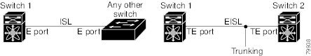
Trunking, also known as VSAN trunking, is a feature specific to switches in the Cisco MDS 9000 Family. Trunking enables interconnect ports to transmit and receive frames in more than one VSAN, over the same physical link, using Extended ISL (EISL) frame format.
Figure 13-1 Trunking
The trunking feature includes the following restrictions:
•
•
•
About Trunking Protocol
The trunking protocol is important for E-port and TE-port operations. It supports the following:
•
•
•
By default, the trunking protocol is enabled. If the trunking protocol is disabled on a switch, no port on that switch can apply new trunk configurations. Existing trunk configurations will not be affected--the TE port continues to function in trunk mode, but only supports traffic in VSANs that it negotiated previously (when the trunking protocol was enabled). Also, other switches that are directly connected to this switch are similarly affected on the connected interfaces. In some cases, you may need to merge traffic from different port VSANs across a non-trunking ISL. If so, disable the trunking protocol.
To avoid inconsistent configurations, shut all E ports before enabling or disabling the trunking protocol.
Configuring Trunk Modes
By default, the trunk mode is enabled in all Fibre Channel interfaces. However, the trunk mode configuration takes effect only in E-port mode. You can configure the trunk mode as on (enabled), off (disabled), or auto (automatic). The default trunk mode is on. The trunk mode configuration at the two ends of an ISL, between two switches, determine the resulting trunking state of the link and the port modes at both ends.
Table 13-1 Trunk Mode Status Between Switches
On
Auto or on
Off
Auto, on, or off
Auto
Auto
When connected to a third-party switch, the trunk mode configuration has no effect--the ISL is always in a trunking disabled state.
Configuring Trunk-Allowed VSAN List
Each Fibre Channel interface has an associated trunk-allowed VSAN list. In TE-port mode, frames are transmitted and received in one or more VSANs specified in this list. By default, the VSAN range (1 through 4093) is included in the trunk-allowed list.
The common set of VSANs that are configured and active in the switch are included in the trunk-allowed VSAN list for an interface, and they are called allowed-active VSANs. The trunking protocol uses the list of allowed-active VSANs at the two ends of an ISL to determine the list of operational VSANs in which traffic is allowed.
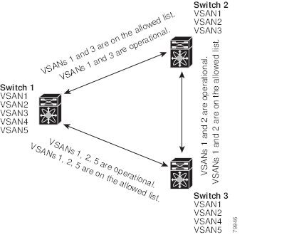
In Figure 13-2, switch 1 has VSANs 1 through 5, switch 2 has VSANs 1 through 3, and switch 3 has VSANs 1, 2, 4, and 5 with a default configuration of trunk-allowed VSANs. All VSANs configured in all three switches are allowed-active. However, only the common set of allowed-active VSANs at the ends of the ISL become operational as shown in.
Figure 13-2 Default Allowed -Active VSAN Configuration
You can configure a select set of VSANs (from the allowed-active list) to control access to those VSANs in a trunking ISL. Using Figure 13-3 as an example, you can configure the list of allowed VSANs on a per-interface basis.
Figure 13-3 Operational and Allowed VSAN Configuration
In Figure 13-3, the operational allowed list of VSANs between switches is as follows:
•
•
•
Consequently, VSAN 2 can only be routed from switch 1 through switch 3 to switch 2.
Trunking Configuration Guidelines
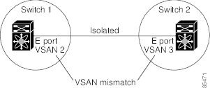
If you misconfigure VSAN configurations across E ports, you could face consequences such as merging the traffic in two VSANs (thus causing both VSANs to mismatch). The trunking protocol validates the VSAN interfaces at both ends of an ISL to avoid VSANs merging. (See Figure 13-4.)
Figure 13-4 VSAN Mismatch
In Figure 13-4, the trunking protocol detects potential VSAN merging and isolates the ports involved.
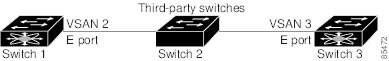
The trunking protocol cannot detect merging of VSANs when a third-party switch is placed in between two Cisco MDS 9000 Family switches. (See Figure 13-5.)
Figure 13-5 Third-Party Switch VSAN Mismatch
VSANs 2 and 3 get effectively merged with overlapping entries in the name server and the zone applications. The Cisco MDS 9000 Fabric Manager helps detect such topologies. Refer to the Cisco MDS 9000 Family Fabric Manager User Guide for more information.
Default Settings
Table 13-2 lists the default settings for trunking parameters.
Table 13-2 Default Trunk Configuration Parameters
Switch port trunk mode
On
Allowed VSAN list
1 to 4093 user-defined VSAN IDs
Trunking protocol
Enabled