-
Cisco MDS 9000 Family Fabric Manager Configuration Guide, Release 1.3 (from Release 1.3(1) through Release 1.3(6))
-
Index
-
New and Changed Information
-
Preface
-
Product Overview
-
Getting Started with Cisco Fabric Manager
-
Overview of Fabric Manager Components
-
Before You Begin
-
Obtaining and Installing Licenses
-
Initial Configuration
-
Configuring High Availability
-
Software Images
-
Managing Modules
-
Managing System Hardware
-
Configuring and Managing VSANs
-
Configuring Interfaces
-
Configuring Trunking
-
Configuring PortChannels
-
Configuring and Managing Zones
-
Configuring Inter-VSAN Routing
-
Managing FLOGI, Name Server, FDMI, and RSCN Databases
-
Configuring Switch Security
-
Configuring Fabric Security
-
Configuring Port Security
-
Configuring Fibre Channel Routing Services and Protocols
-
Configuring IP Services
-
Configuring FICON
-
Configuring IP Storage
-
Configuring Call Home
-
Configuring Domain Parameters
-
Configuring Traffic Management
-
Configuring System Message Logging
-
Discovering SCSI Targets
-
Monitoring Network Traffic Using SPAN
-
Advanced Features and Concepts
-
Configuring Fabric Configuration Servers
-
Monitoring System Processes and Logs
-
Troubleshooting the Fabric
-
Troubleshooting Fabric Manager Issues
-
 Feedback
Table Of Contents
Configuring Fibre Channel Routing Services and Protocols
Fail-over Scenarios for PortChannels and FSPF Links
Managing FSPF General Attributes
Disabling FSPF Routing Protocols
Configuring FSPF for a Specific Interface
Specifying Hello Time Intervals
Disabling FSPF for Specific Interfaces
Viewing FSPF Interface Statistics
Configuring Fibre Channel Routes
Configuring Fibre Channel Route Flows
Configuring Fibre Channel Routing Services and Protocols
Fabric Shortest Path First (FSPF) is the standard path selection protocol used by Fibre Channel fabrics. The FSPF feature is enabled by default on all Fibre Channel switches. Except in configurations that require special consideration, you do not need to configure any FSPF services. FSPF automatically calculates the best path between any two switches in a fabric. Specifically, FSPF is used to:
•
Dynamically compute routes throughout a fabric by establishing the shortest and quickest path between any two switches.
•
–
–
This chapter provides details on Fibre Channel routing services and protocols.
This chapter contains the following topics:
•
•
FSPF Features
FSPF is the protocol currently standardized by the T11 committee for routing in Fibre Channel networks. The FSPF protocol has the following characteristics and features:
•
•
•
•
•
•
•
FSPF Examples
This section provides examples of topologies and applications that demonstrate the benefits of FSPF. The FSPF feature can be used on any topology.
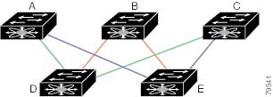
Fault Tolerant Fabric
Figure 21-1 depicts a fault tolerant fabric using a partial mesh topology. If a link goes down anywhere in the fabric, any switch can still communicate with all others in the fabric. In the same way, if any switch goes down, the connectivity of the rest of the fabric is preserved.
Figure 21-1 Fault Tolerant Fabric
For example, if all links are of equal speed, the FSPF calculates two equal paths from A to C: A-D-C (green) and A-E-C (blue).
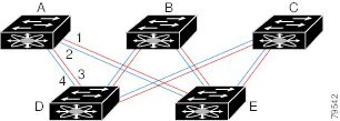
Redundant Links
To further improve on the topology in, each connection between any pair of switches can be replicated; two or more links can be present between a pair of switches. shows this arrangement. Because switches in the Cisco MDS 9000 Family support PortChanneling, each pair of physical links can appear to the FSPF protocol as one single logical link.
By bundling pairs of physical links, FSPF efficiency is considerably improved by the reduced database size and the frequency of link updates. Once physical links are aggregated, failures are not attached to a single link but to the entire PortChannel. This configuration also improves the resiliency of the network. The failure of a link in a PortChannel does not trigger a route change, thereby reducing the risks of routing loops, traffic loss, or fabric downtime for route reconfiguration.
Figure 21-2 Fault Tolerant Fabric with Redundant Links
For example, if all links are of equal speed and no PortChannels exist, the FSPF calculates four equal paths from A to C: A1-E-C, A2-E-C, A3-D-C, and A4-D-C. If PortChannels exist, these paths are reduced to two.
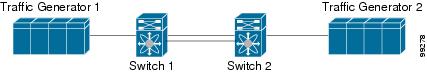
Fail-over Scenarios for PortChannels and FSPF Links
The SmartBits traffic generator was used evaluate the scenarios displayed in Figure 21-3 and summarized in Table 21-1 and Table 21-2. Two links between switch 1 and switch 2 exist as either equal-cost ISLs or PortChannels. There is one flow from traffic generator 1 to traffic generator 2. The traffic was tested at 100 utilization of 1G in two scenarios:
•
•
Figure 21-3 Fail-over Scenario Using Traffic Generators
Configuring FSPF Globally
Some FSPF features can be globally configured in each VSAN. By configuring a feature for the entire VSAN, you do not have to specify the VSAN number for every command. This global configuration feature also reduces the chance of typing errors or other minor configuration errors.
FSPF is enabled by default. Generally, you do not need to configure these advanced features.
Caution
Managing FSPF General Attributes
To manage FSPF general attributes, perform the following steps:
Step 1
From the Device Manager, choose FC > FSPF and click the General tab.
The Information pane from the Fabric Manager displays information for multiple switches. The dialog box from the Device Manager displays FSPF information for a single switch.
Step 2
Disabling FSPF Routing Protocols
By default, FSPF is enabled on switches in the Cisco MDS 9000 Family.
Link State Record Defaults
Each time a new switch enters the fabric, a link state record (LSR) is sent to the neighboring switches, and then flooded throughout the fabric. displays the default settings for switch responses.
Viewing Link State Records
To monitor FSPF LSRs from the Device Manager, choose FC > FSPF and click the LSDB LSRs tab.
Viewing FSPF Links
To view FSPF links from the Device Manager, choose FC > FSPF and click the LSDB Links tab.
Configuring FSPF for a Specific Interface
Several FSPF commands are available on a per interface basis. The following configuration procedures apply to an interface in a specific VSAN and are described in this section.
This section contains the following topics:
•
•
•
Configuring FSPF Interfaces
To configure FSPF interfaces, perform the following steps:
Step 1
To configure FSPF interfaces from the Device Manager, choose FC > FSPF and click the Interfaces tab.
Step 2
Computing Route Cost
FSPF tracks the state of links on all switches in the fabric, associates a cost with each link in its database, and then chooses the path with a minimal cost. The cost associated with an interface can be administratively changed to implement the FSPF route selection. The integer value to specify cost can range from 1 to 65,535 seconds. The default cost for 1Gbps is 1000 and 2Gbps is 500 seconds
Specifying Hello Time Intervals
You can set the FSPF hello time interval to specify the interval between the periodic hello messages sent to verify the health of the link. The integer value can range from 1 to 65,535 seconds.
This value must be the same in the ports at both ends of the ISL.
Specifying Dead Intervals
You can set the FSPF dead time interval to specify the maximum interval for which a hello message must be received before the neighbor is considered lost and removed from the database. The integer value can range from 1 to 65,535 seconds.
This value must be the same in the ports at both ends of the ISL.
Caution
Disabling FSPF for Specific Interfaces
You can disable the FSPF protocol for selected interfaces. By default, FSPF is enabled on all E ports and TE ports. This default can be disabled by setting the interface as passive.
FSPF must be enabled at both ends of the interface for the protocol to work.
Retransmitting Intervals
You can specify the time after which an unacknowledged link state update should be transmitted on the interface. The integer value to specify retransmit intervals can range from 1 to 65,535 seconds.
This value must be the same on the switches on both ends of the interface.
Viewing FSPF Interface Statistics
To monitor FSPF interface statistics from the Fabric Manager, choose FC > FSPF on the menu tree and click the Interface Stats tab.
To monitor FSPF interface statistics from the Device Manager, choose FC > FSPF and click the Interface Stats tab.
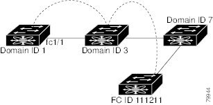
Configuring Fibre Channel Routes
Each port implements forwarding logic, which forwards frames based on its FC ID. To configure the FC ID for the specified interface and domain, you can configure the specified route (for example FC ID 111211 and domain ID 3) in the switch with domain ID 1.
Figure 21-4 Fibre Channel Routes
Other than in VSANs, run time checks are not performed on configured and suspended static routes.
To configure Fibre Channel routes, perform the following steps:
Step 1
Step 2
Step 3
You see the Create Route dialog box.
Step 4
Step 5
Configuring Fibre Channel Route Flows
To view Fibre Channel flows and add a route flow, perform the following steps:
Step 1
From the Device View, choose FC > Routes and click the Flow Statistics tab. The dialog box from the Device Manager displays flows for a single switch.
Step 2
Step 3
To add a route flow from Device Manager, click Create in the dialog box.
You see the Create Route Flow dialog box.
Step 4
Broadcast Routing
Broadcast in a Fibre Channel fabric uses the concept of a distribution tree to reach all switches in the fabric (for broadcast traffic).
FSPF provides the topology information to compute the distribution tree. Fibre Channel defines 256 multicast groups and one broadcast address for each VSAN. Switches in the Cisco MDS 9000 Family only use broadcast routing. By default, they use the principal switch as the root node to derive the distribution tree information. The protocols create a loop-free broadcast distribution tree.
Caution
In-Order Delivery
In-order delivery of data frames guarantees frame delivery to a destination in the same order that they were sent by the originator.
Some Fibre Channel protocols or applications cannot handle out-of-order frame delivery. In these cases, switches in the Cisco MDS 9000 Family preserve frame ordering in the frame flow. The source ID (SID), destination ID (DID), and optionally the originator exchange ID (OX ID) identify the flow of the frame.
In case of a single switch, all frames received by a specific ingress port and destined to a certain egress port are always delivered in the same order in which they were received.
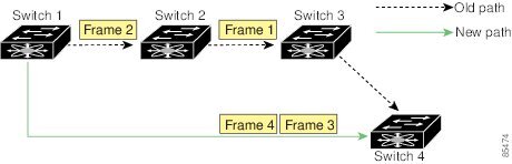
Reordering Network Frames
When you experience a route change in the network, the new selected path may be faster or less congested than the old route.
Figure 21-5 Route Change Delivery
In Figure 21-5, the new path from Switch 1 to Switch 4 is faster. Hence, Frame 3 and Frame 4 may be delivered before Frame 1 and Frame 2.
If the in-order guarantee feature is enabled, the frames within the network are treated as specified below:
•
•
•
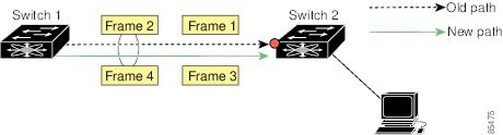
Reordering PortChannel Frames
When a link change occurs in a PortChannel, the frames for the same exchange or the same flow can switch from one path to another faster path.
Figure 21-6 Link Congestion Delivery
In Figure 21-6, the port of the old path (red dot) is congested. Hence Frame 3 and Frame 4 can be delivered before Frame 1 and Frame 2.
When the in-order guarantee feature is enabled, the frames crossing a PortChannel are treated as specified below:
•
•
•
Enabling In-Order Delivery
By default, in-order delivery is disabled on switches in the Cisco MDS 9000 Family.
Tip
Configuring Flow Statistics
Flow statistics count the ingress traffic in the aggregated statistics table. You can collect two kinds of statistics:
•
•
If you enable flow counters, you can enable a maximum of 1K entries for aggregate flow and flow statistics. Be sure to assign an unused flow index to a module for each new flow. Flow indexes can be repeated across modules. The number space for flow index is shared between the aggregate flow statistics and the flow statistics.
Viewing FSPF Statistics
To monitor FSPF statistics from the Fabric Manager, choose FC > FSPF on the menu tree and click the Statistics tab.
To monitor FSPF statistics from the Device Manager, choose FC > FSPF and click the Statistics tab.
Default Settings
Table 21-4 lists the default settings for FSPF features.