-
Cisco MDS 9000 Family Fabric Manager Configuration Guide, Release 1.3 (from Release 1.3(1) through Release 1.3(6))
-
Index
-
New and Changed Information
-
Preface
-
Product Overview
-
Getting Started with Cisco Fabric Manager
-
Overview of Fabric Manager Components
-
Before You Begin
-
Obtaining and Installing Licenses
-
Initial Configuration
-
Configuring High Availability
-
Software Images
-
Managing Modules
-
Managing System Hardware
-
Configuring and Managing VSANs
-
Configuring Interfaces
-
Configuring Trunking
-
Configuring PortChannels
-
Configuring and Managing Zones
-
Configuring Inter-VSAN Routing
-
Managing FLOGI, Name Server, FDMI, and RSCN Databases
-
Configuring Switch Security
-
Configuring Fabric Security
-
Configuring Port Security
-
Configuring Fibre Channel Routing Services and Protocols
-
Configuring IP Services
-
Configuring FICON
-
Configuring IP Storage
-
Configuring Call Home
-
Configuring Domain Parameters
-
Configuring Traffic Management
-
Configuring System Message Logging
-
Discovering SCSI Targets
-
Monitoring Network Traffic Using SPAN
-
Advanced Features and Concepts
-
Configuring Fabric Configuration Servers
-
Monitoring System Processes and Logs
-
Troubleshooting the Fabric
-
Troubleshooting Fabric Manager Issues
-
 Feedback
Table Of Contents
Configuring Gigabit Ethernet Interfaces
About Gigabit Ethernet Interfaces
Basic Gigabit Ethernet Configuration
About VLANs for Gigabit Ethernet
Verifying Gigabit Ethernet Connectivity
Gigabit Ethernet High Availability
Configuring Ethernet PortChannels
Creating FCIP Tunnels with Device Manager
Verifying Extended Link Protocols (ELP)
Creating FCIP Tunnels with Fabric Manager
Advanced FCIP Profile Configuration
Configuring TCP Listener Ports
Advanced FCIP Interface Configuration
Configuring the Number of TCP Connections
Configuring FCIP Write Acceleration
Ethernet PortChannels and Fibre Channel PortChannels
Routing iSCSI Requests and Responses
Presenting Fibre Channel Targets as iSCSI Targets
iSCSI Virtual Target Configuration Examples
Presenting iSCSI Hosts as Virtual Fibre Channel Hosts
Making the Dynamic Initiator WWN Mapping Static
Assigning VSAN Membership to iSCSI Hosts
Assigning VSANs to a iSCSI Interface
Configuring iSCSI Proxy Initiators
Configuring the iSCSI Proxy Initiator
Fibre Channel Zoning-Based Access Control
Configuring an Authentication Mechanism
Configuring an iSCSI RADIUS Server
Multiple IPS Ports Connected to the Same IP Network
Ethernet PortChannel-Based High Availability
iSCSI Authentication Setup Guidelines
Configuring Storage Name Services
Creating iSNS Profiles and Tagging Profiles
Associating IP Profiles to Interfaces
Configuring IP Storage
Cisco MDS 9000 Family IP storage (IPS) services modules extend the reach of Fibre Channel SANs by using open-standard, IP-based technology. The switch connects separated SAN islands using Fibre Channel over IP (FCIP), and allows IP hosts to access Fibre Channel storage using iSCSI protocol.
FCIP and iSCSI features are specific to the IPS module and can be implemented in Cisco MDS 9216 switches or Cisco MDS 9500 Directors running Cisco MDS SAN-OS Release 1.1(x) or above.
This chapter contains the following topics:
•
Configuring Gigabit Ethernet Interfaces
•
•
•
IP Storage Services Module
The IPS services module (IPS module) allows you to use FCIP and iSCSI features. It integrates seamlessly into the Cisco MDS 9000 Family, and supports the full range of features available on other switching modules, including VSANs, security, and traffic management.
The following types of IPS modules are currently available for use in any Cisco MDS 9216 switch or any switch in the Cisco MDS 9500 Series:
•
•
Each port in either module can be configured to support FCIP protocol, iSCSI protocol, or both protocols simultaneously.
•
Figure 24-1 FCIP Scenarios
•
Figure 24-2 iSCSI Scenarios
Configuring Gigabit Ethernet Interfaces
This section contains the following topics:
•
•
•
•
•
About Gigabit Ethernet Interfaces
Both FCIP and iSCSI rely on TCP/IP for network connectivity. On the IPS module, connectivity is provided in the form of Gigabit Ethernet interfaces that are appropriately configured. This section covers the steps required to configure IP for subsequent use by FCIP and iSCSI.
A new port mode, called IPS, is defined for Gigabit Ethernet ports on the IPS module. IP storage ports are implicitly set to IPS mode, so they can only be used to perform iSCSI and FCIP storage functions. IP storage ports do not bridge Ethernet frames or route other IP packets.
Tip
Basic Gigabit Ethernet Configuration
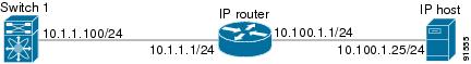
Figure 24-3 depicts a basic Gigabit Ethernet configuration.
Figure 24-3 Gigabit Ethernet Configuration
You can configure the switch to receive and transfer large (or jumbo) frames on a port. The default IP MTU frame size is 1500 bytes for all Ethernet ports. By configuring jumbo frames on a port, the MTU size can be increased to 9000 bytes. The following example sets the size to 3000 bytes. Independent of the MTU size, the IPS module does not pack multiple IP frames (converted to FCIP or to iSCSI).
The minimum MTU size for a port running iSCSI is 512 bytes.
About VLANs for Gigabit Ethernet
Virtual LANs (VLANs) create multiple virtual Layer 2 networks over a physical LAN network. VLANs provide traffic isolation, security, and broadcast control.
IPS gigabit ethernet ports automatically recognize Ethernet frames with IEEE 802.1Q VLAN encapsulation. If you need to have traffic from multiple VLANs terminated on one IPS port, configure subinterfaces—one for each VLAN. Use the VLAN ID as a subscription to the Gigabit Ethernet interface name to create the subinterface name <the slot-number>/<port-number>.<VLAN-ID>).
If the IPS module is connected to a Cisco Ethernet switch, and you need to have traffic from multiple VLANs coming to one IPS port, verify the following requirements on the Ethernet switch:
•
•
Verifying Gigabit Ethernet Connectivity
The ping command sends echo request packets out to a remote device at an IP address that you specify.
Once the Gigabit Ethernet interfaces are connected with valid IP addresses, verify the interface connectivity on each switch using the ping command. Ping the IP host using the IP address of the host to verify that the static IP route is configured correctly.
If the connection fails, verify the following, and repeat the ping command:
•
•
•
•
•
Gigabit Ethernet High Availability
Virtual Router Redundancy Protocol (VRRP) and Ethernet PortChannels are two Gigabit Ethernet features that provide high availability for iSCSI and FCIP services.
Configuring VRRP
VRRP provides a redundant alternate path to the Gigabit Ethernet port for iSCSI and FCIP services.
VRRP provides IP address fail over protection to an alternate Gigabit Ethernet interface so the IP address is always available.
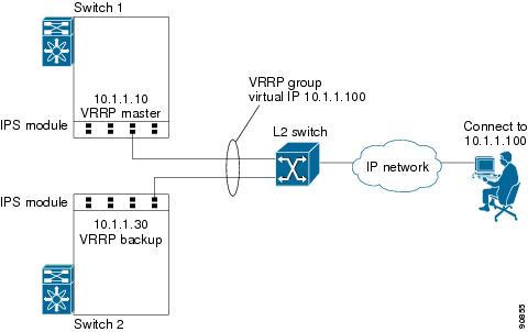
Figure 24-4 VRRP Scenario
In Figure 24-4, all members of the VRRP group must be IP storage Gigabit Ethernet ports. VRRP group members can be one or more of the following interfaces:
•
•
•
•
•
•
The VRRP preempt option is not supported on IP storage Gigabit Ethernet interfaces. However, if the virtual IP address is also the IP address for the interface, then preemption is implicitly applied.
Configuring Ethernet PortChannels
Ethernet PortChannels refer to the aggregation of multiple physical Gigabit Ethernet interfaces into one logical Ethernet interface to provide link redundancy and, in some cases, higher aggregated bandwidth and load balancing.
The data traffic from one TCP connection always travels on the same physical links. An Ethernet switch connecting to the MDS Gigabit Ethernet port can implement load balancing based on its IP address, its source-destination MAC address, or its IP and port. In iSCSI scenarios if the Ethernet switch is not capable of load-balancing based on the IP address or the IP port, multiple iSCSI initiators are required to take advantage of the Ethernet PortChannel feature.
The Cisco Ethernet switch's PortChannel should be configured as a static PortChannel, and not the default 802.3aa protocol.
Ethernet PortChannels can only aggregate two physical interfaces that are adjacent to each other on a given IPS module.
PortChannel members must be one of these combinations: ports 1-2, ports 3-4, ports 5-6, or ports 7-8.
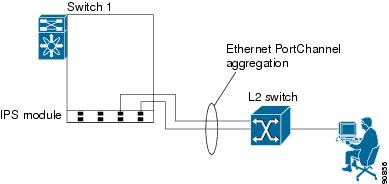
Figure 24-5 Ethernet PortChannel Scenario
In Figure 24-5, Gigabit Ethernet ports 3 and 4 in slot 9 are aggregated into an Ethernet PortChannel.
All FCIP data traffic for one FCIP link is carried on one TCP connection. Consequently, the aggregated bandwidth will be one Gbps for that FCIP link.
PortChannel configuration specified in also apply to Ethernet PortChannel configurations.
PortChannel interfaces provide configuration options for both Gigabit Ethernet and Fibre Channel. However, based on the PortChannel membership, only Gigabit Ethernet parameters or Fibre Channel parameters are applicable.
Gigabit Ethernet interfaces cannot be added to a
PortChannel if one of the following cases apply: - if the interface already has an IP address assigned, or - if subinterfaces are configured on that interface.
Configuring CDP
The Cisco Discovery Protocol (CDP) is supported on the management Ethernet interface on the supervisor module and the Gigabit Ethernet interface on the IPS module.
IPS Core Dumps
IPS core dumps are different from the system kernel core dumps for other modules. When the IPS module operating system (OS) unexpectedly resets, it is sometimes useful to obtain a copy of the memory image (called a IPS core dump) to identify the cause of the reset. Under that condition, the IPS module sends the core dump to the supervisor module for storage. Core dumps take up significant space and hence the level of what gets stored can be configured using one of the two options:
•
•
Configuring FCIP
This section contains the following topics:
•
•
•
•
•
About FCIP
The Fibre Channel over IP Protocol (FCIP) is a tunneling protocol that connects geographically distributed Fibre Channel storage area networks (SAN islands) transparently over IP local area networks (LANs), metropolitan area networks (MANs), and wide area networks (WANs).
FCIP uses TCP as a network layer transport.
To configure the IPS module for FCIP, you should have a basic understanding of the following concepts:
•
•
•
•
FCIP and VE Ports
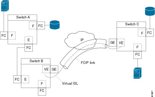
Figure 24-6 describes the internal model of FCIP with respect to Fibre Channel inter switch links (ISLs) and Cisco's enhanced ISLs (EISLs).
FCIP defines virtual E (VE) ports, which behave exactly like standard Fibre Channel E ports, except that the transport in this case is FCIP instead of Fibre Channel. The only requirement is for the other end of the VE port to be another VE port.
A virtual ISL is established over a FCIP link and transports Fibre Channel traffic. Each associated virtual ISL looks like a Fibre Channel ISL with either an E port or a TE port at each end.
Figure 24-6 FCIP Links and Virtual ISLs
FCIP Link
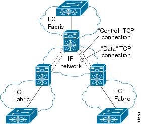
FCIP links consist of one or more TCP connections between two FCIP link end points. Each link carries encapsulated Fibre Channel frames.
When the FCIP link comes up, the VE ports at both ends of the FCIP link create a virtual Fibre Channel (E)ISL and initiate the E port protocol to bring up the (E)ISL.
By default, the FCIP feature on any Cisco MDS 9000 Family switch creates two TCP connections for each FCIP link.
•
•
To enable FCIP on the IPS module, a FCIP profile and FCIP interface (interface FCIP) must be configured.
The FCIP link is established between two peers, the VE port initialization behavior is identical to a normal E port. This behavior is independent of the link being FCIP or pure Fibre Channel, and is based on the E port discovery process (ELP, ESC).
Once the FCIP link is established, the VE port behavior is identical to E port behavior for all inter-switch communication (including domain management, zones, and VSANs). At the Fibre Channel layer, all VE and E port operations are identical.
FCIP Profiles
The FCIP profile contains information about local IP address and TCP parameters. The profile defines the following information:
•
•
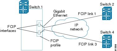
The FCIP profile's local IP address determines the Gigabit Ethernet port where the FCIP links terminates.
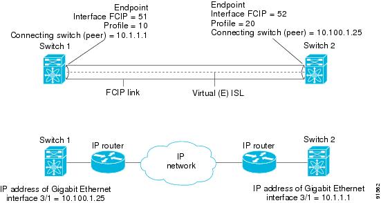
Figure 24-7 FCIP Profile and FCIP Links
FCIP Interface
The FCIP interface is the local end point of the FCIP link and a VE port interface. All the FCIP and E port parameters are configured in context to the FCIP interface.
The FCIP parameters consist of the following:
•
•
•
•
Enabling FCIP
To begin configuring the FCIP feature, you must explicitly enable FCIP on the required switches in the fabric. By default, this feature is disabled in all switches in the Cisco MDS 9000 Family.
The configuration and verification commands for the F IP feature are only available when FCIP is enabled on a switch. When you disable this feature, all related configurations are automatically discarded.
Basic FCIP Configuration
To configure a FCIP link, follow these steps on both switches.
Step 1
Step 2
Step 3
Step 4
Step 5
Creating FCIP Profiles
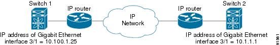
To create a FCIP profile, you must assign a local IP address of a Gigabit Ethernet interface or subinterface to the FCIP profile.
Figure 24-8 Assigning Profiles to Each Gigabit Ethernet Interface
Creating FCIP Links
When two FCIP link end points are created, a FCIP link is established between the two IPS modules. To create a FCIP link, assign a profile to the FCIP interface and configure the peer information. The peer IP switch information initiates (creates) a FCIP link to that peer switch.
Figure 24-9 Assigning Profiles to Each Gigabit Ethernet Interface
Creating FCIP Tunnels with Device Manager
To create and manage FCIP tunnels with Device Manager, first verify that the IPS module is inserted in the required Cisco MDS 9000 Family switches, and that the switches' Gigabit Ethernet interfaces are connected and the connectivity verified using the ping command. The steps in creating FCIP tunnels are:
Assigning FCIP Profiles
You can use Device Manager to configure FCIP tunnels between switches. First, you must create FCIP profiles, and then bind the interfaces to the profile. To bind an FCIP profile to an interface, use the IP address of the interface in the FCIP profile's IP address configuration. Profile numbers range from 1 to 255. The interface associated with a profile can be either of the following:
•
•
To create and bind profiles on a Gigabit Ethernet interface, follow these steps.
Step 1
Step 2
Step 3
Step 4
Step 5
Step 6
Step 7
Step 8
Step 9
Creating Tunnels
Each Gigabit Ethernet interface can have three active FCIP tunnels on it at one time.
To create these tunnels, follow these steps:
Step 1
Step 2
Step 3
Step 4
Step 5
Step 6
Step 7
Step 8
Step 9
Verifying Interfaces
To verify the interfaces, follow these steps:
Step 1
Step 2
Step 3
Step 4
Verifying Extended Link Protocols (ELP)
To verify the extended link protocol, follow these steps:
Step 1
Step 2
Step 3
Step 4
Checking Trunk Status
To check the trunk status, follow these steps:
Step 1
Step 2
Step 3
Step 4
Checking for Interface Errors
To check for interface errors, follow these steps:
Step 1
Step 2
Step 3
Step 4
Creating FCIP Tunnels with Fabric Manager
To create and manage FCIP tunnels with Fabric Manager, you use the FCIP Wizard. First verify that the IPS module is inserted in the required Cisco MDS 9000 Family switches, and that the switches' Gigabit Ethernet interfaces are connected and the connectivity verified. The steps in creating FCIP tunnels using the FCIP Wizard are:
•
•
•
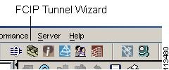
To create FCIP tunnels using the FCIP Wizard, follow these steps:
Step 1
Figure 24-10 FCIP Tunnels Wizard
Step 2
Step 3
Step 4
Advanced FCIP Profile Configuration
A basic FCIP configuration uses the local IP address to configure the FCIP profile. In addition to the local IP address and the local port, you can specify other TCP parameters as part of the FCIP profile configuration.
FCIP configuration options can be accessed from the switch(config- profile)# submode prompt.
Configuring TCP Listener Ports
The default TCP port for FCIP is 3225. You can change this port using the port command.
Configuring TCP Parameters
This section provides details on the TCP parameters that can be configured to control TCP behavior in a switch. The following TCP parameters can be configured.
Minimum Retransmit Timeout
The tcp minimum-retransmit-time option controls the minimum amount of time TCP waits before retransmitting. By default, this value is 200 milliseconds.
Keepalive Timeout
The tcp keepalive-timeout option enables you to configure the interval between which the TCP connection verifies if the FCIP link is functioning. This ensures that a FCIP link failure is detected quickly even when there is no traffic.
If the TCP connection is idle for more than the specified time, then keepalive timeout packets are sent to ensure that the connection is active. This command can be used to tune the time taken to detect FCIP link failures.
The first interval during which the connection is idle is 60 seconds (default). When the connection is idle for 60 seconds, 8 keepalive probes are sent at 1-second intervals. If no response is received for these 8 probes and the connection remains idle throughout, that FCIP link is automatically closed.
Only the first interval (during which the connection is idle) can be changed from the default of 60 seconds. This interval is identified using the keepalive-timeout
option. The valid range is from 1 to 7200 seconds.
Maximum Retransmissions
The tcp max-retransmissions option specifies the maximum number of times a packet is retransmitted before TCP decides to close the connection.
Path MTU
Path MTU (PMTU) is the minimum MTU on the IP network between the two end points of the FCIP link. PMTU discovery is a mechanism by which TCP learns of the PMTU dynamically and adjusts the maximum TCP segment accordingly (RFC 1191).
By default, PMTU discovery is enabled on all switches with a default timeout of 3600 seconds. If TCP reduces the size of the max segment because of PMTU change, the reset-timeout specifies the time after which TCP tries the original MTU.
SACK
TCP may experience poor performance when multiple packets are lost within one window. With the limited information available from cumulative acknowledgments, a TCP sender can only learn about a single lost packet per round trip time. A selective acknowledgment (SACK) mechanism helps overcome the limitations of multiple lost packets during a TCP transmission.
The receiving TCP sends back SACK advertisements to the sender. The sender can then retransmit only the missing data segments. By default, SACK is enabled on Cisco MDS 9000 Family switches.
Window Management
The optimal TCP window size is computed using the max-bandwidth option, the min-available-bandwidth option, and the dynamically-measured round-trip-time (RTT). The interaction and the resulting TCP behavior is outlined below:
The configured round-trip-time option determines the window scaling factor of the TCP connection. This option is only an approximation. The measured RTT value overrides the round-trip-time option for window management. If the configured round-trip-time is too small compared to the measured RTT, then the link may not be fully utilized due to the window scaling factor being too small.
•
•
•
The maximum-bandwidth option and the measured round-trip-time together determine the maximum window size.
The min-available-bandwidth option and the measured round-trip-time together determine the threshold below which TCP aggressively maintains a window size sufficient to transmit at min-available-bandwidth. The software uses standard TCP rules to increase the window beyond the one required to maintain the min-available-bandwidth in order to reach the max-bandwidth. The defaults are max-bandwidth = 1G, min-available-bandwidth = 15 Mbps, and round-trip-time =1 ms.
Buffer Size
The send-buffer-size option defines the required additional buffering (beyond the normal send window size) that TCP allows before flow controlling the switch's egress path for the FCIP interface. The default buffer size is 0 KB.
Quality of Service
The Quality of Service (QoS) feature specifies the differentiated services code point (DSCP) value to mark all IP packets (type of service—STOS field in the IP header).
•
•
If the FCIP link has only one TCP connection, that data DSCP value is applied to all packets in that connection.
Monitoring Window Congestion
The congestion window monitoring (CWM) option determines the maximum burst size allowed after an idle period.
•
•
By default the tcpcwm option is enabled and the default burst size is 10 KB.
Tip
Advanced FCIP Interface Configuration
You can establish connection to a peer by configuring one or more of the following options for the FCIP interface. To do so, you must first create the interface and enter the config-if submode.
Configuring Peers
To establish a FCIP link with the peer, you can use one of two options:
•
•
Peer IP Address
The basic FCIP configuration uses the peer's IP address to configure the peer information. You can also specify the peer's port number to configure the peer information. If you do not specify a port, the default 3225 port number is used to establish connection.
Special Frames
You can alternatively establish a FCIP link with a peer using an optional protocol called special frames. You can enable or disable the special-frame option. On the peer side, the special-frame option must be enabled in order to establish the FCIP link. When the special-frame option is enabled, the peer IP address (and optionally the port or the profile ID) only needs to be configured on one end of the link. Once the connection is established, a special frame is exchanged to discover and authenticate the link.
By default, the special frame feature is disabled.
Refer to the Fibre Channel IP standards for further information on special frames.
Tip
Configuring Active Connection
Use the passive-mode option to configure the required mode for initiating an IP connection. By default, active mode is enabled to actively attempt an IP connection.
If you enable the passive mode, the switch does not initiate a TCP connection and merely waits for the peer to connect to it.
Ensure that both ends of the FCIP link are not configured as passive mode. If both ends are configured as passive, the connection will not be initiated.
Configuring the Number of TCP Connections
Use the tcp-connection option to specify the number of TCP connections from a FCIP link. By default, the switch tries two (2) TCP connections for each FCIP link. You can configure 1 or 2 TCP connections.
For example, the Cisco PA-FC-1G Fibre Channel port adapter which has only 1 (one) TCP connection interoperates with any switch in the Cisco MDS 9000 Family. One TCP connection is within the specified limit and you can change the configuration on the switch using the tcp-connection 1 command. If the peer initiates one TCP connection, and your MDS switch is configured for two TCP connections, the software handles it gracefully and moves on with just one connection.
Enabling Time Stamps
Use the time-stamp option to enable or disable FCIP time stamps on a packet. The time stamp option instructs the switch to discard packets that are outside the specified time. By default, the time-stamp option is disabled.
The acceptable-diff option specifies the time range within which packets can be accepted. If the packet arrived within the range specified by this option, the packet is accepted. Otherwise, it is dropped. By default if a packet arrives within a 1000 millisecond interval (+ or -1000 milliseconds), that packet is accepted.
If the time-stamp option is enabled, be sure to configure NTP on both switches.
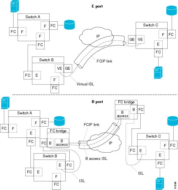
B Port Interoperability Mode
While E ports typically interconnect Fibre Channel switches, some SAN extender devices, such as Cisco's PA-FC-1G Fibre Channel port adapter and the SN 5428-2 storage router, implement a bridge port model to connect geographically dispersed fabrics. This model uses B port as described in the T11 Standard FC-BB-2. depicts a typical SAN extension over an IP network.
Figure 24-11 FCIP B Port and Fibre Channel E Port
B ports bridge Fibre Channel traffic from one E port to a remote E port without participating in fabric-related activities such as principal switch election, Domain ID assignment, and Fibre Channel routing (FSPF). For example, Class F traffic entering a SAN extender does not interact with the B port. The traffic is transparently propagated (bridged) over a WAN interface before exiting the remote B port. This bridge results in both E ports exchanging Class F information which ultimately leads to normal ISL behavior such as fabric merging and routing.
FCIP links between B port SAN extenders do not exchange the same information as FCIP links between E ports, and are therefore incompatible. This is reflected by the terminology used in FC-BB-2: while VE ports establish a virtual ISL over a FCIP link, B ports use a B access ISL.
The IPS module supports FCIP links that originate from a B port SAN extender device by implementing the B access ISL protocol on a Gigabit Ethernet interface. Internally, the corresponding virtual B port connects to an virtual E port which completes the end-to-end E port connectivity requirement.
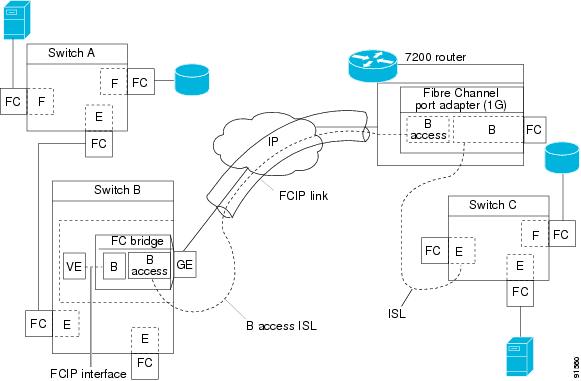
Figure 24-12 FCIP Link Terminating in a B Port Mode
The B port feature in the IPS module allows remote B port SAN extenders to communicate directly with a Cisco MDS 9000 Family switch, therefore eliminating the need for local bridge devices.
Configuring B Ports
When a FCIP peer is a SAN extender device that only supports Fibre Channel B ports, you need to enable the B port mode for the FCIP link. When a B port is enabled, the E port functionality is also enabled and they coexist. If the B port is disabled, the E port functionality remains enabled.
E Port Configurations
All configuration commands that apply to E ports, also apply to FCIP interfaces. The following features are also available FCIP interfaces:
•
–
–
–
–
–
–
–
–
–
–
–
–
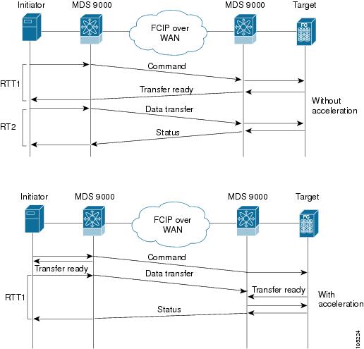
Configuring FCIP Write Acceleration
The FCIP Write Acceleration feature in SAN-OS 1.3(3) enables you to significantly improve application performance when storage traffic is routed over wide area networks using FCIP. When FCIP Write Acceleration is enabled, WAN throughput is maximized by minimizing the impact of WAN latency for the command to transfer ready acknowledgement.
The write acceleration feature is disabled by default and must be enabled on both sides of the FCIP link. If it is only enabled on one side of the FCIP tunnel, the tunnel will not initialize.
Figure 24-13 FCIP Link Write Acceleration
In Figure 24-13, some data sent by the host is queued on the target before the target issues a Transfer Ready. This way the actual write operation may be done in a less time than the write operation without the write acceleration feature being enabled.
Tip
Enabling FCIP Compression
The FCIP compression feature introduced in Release 1.3(x) allows IP packets to be compressed on the FCIP link if this feature is enabled on that link. By default the FCIP compression is disabled.
This feature uses the Lempel-Zif-Stac (LZS) compression algorithm to compress packets.
The high-throughput mode allows faster compression but the compression ratio may be lower. The high-comp-ratio mode allows a higher compression ratio, but the throughput may be lower.
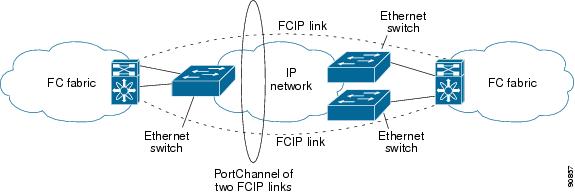
Fibre Channel PortChannels
Figure 24-14 provides an example of a PortChannel-based load balancing configuration. To perform this configuration, you need two IP addresses on each SAN island. This solution addresses link failures.
Figure 24-14 PortChannel Based Load Balancing
The following characteristics set Fibre Channel PortChannel solutions apart from other solutions:
•
•
•
FSPF
Figure 24-15 displays a FPSF-based load balancing configuration example. This configuration requires two IP addresses on each SAN island, and addresses IP and FCIP link failures.
Figure 24-15 FSPF-Based Load Balancing
The following characteristics set FSPF solutions apart from other solutions:
•
•
•
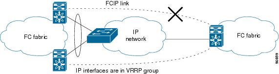
VRRP
displays a VRRP-based high availability FCIP configuration example. This configuration, requires at least two physical Gigabit Ethernet ports connected to the Ethernet switch on the island where you need to implement high availability using VRRP.
Figure 24-16 VRRP-Based High Availability
The following characteristics set VRRP solutions apart from other solutions:
•
•
•
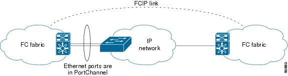
Ethernet PortChannels
Figure 24-17 displays a Ethernet PortChannel-based high availability FCIP example. This solution addresses the problem caused by individual Gigabit Ethernet link failures.
Figure 24-17 Ethernet PortChannel-Based High Availability
The following characteristics set Ethernet PortChannel solutions apart from other solutions:
•
•
•
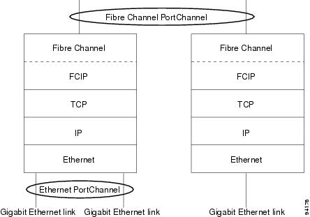
Ethernet PortChannels and Fibre Channel PortChannels
Ethernet PortChannels offer Ethernet-level redundancy, Fibre Channel PortChannels offer (E)ISL-level redundancy. FCIP is unaware of any Ethernet PortChannels or Fibre Channel PortChannels. Fibre Channel PortChannels are unaware of any Ethernet PortChannels, and there is no mapping between the two.
Figure 24-18 PortChannels at the Fibre Channel and Ethernet Levels
Configuring iSCSI
This section contains the following topics:
•
•
•
•
•
About iSCSI
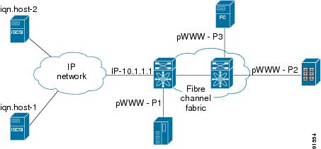
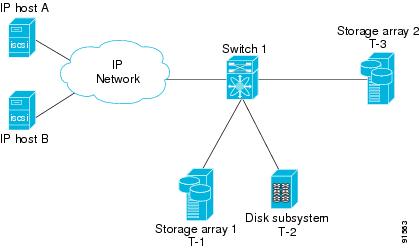
The IPS module provides transparent SCSI routing by default. IP hosts using iSCSI protocol can transparently access targets on the Fibre Channel network. provides an example of a typical configuration of iSCSI hosts with access to a Fibre Channel SAN.
Figure 24-19 Typical IP to Fibre Channel SAN Configuration
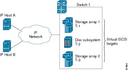
The IPS module enables you to create virtual iSCSI targets and maps them to physical Fibre Channel targets available in the Fibre Channel SAN. They present the Fibre Channel targets to IP hosts as if the physical targets were attached to the IP network.
Figure 24-20 iSCSI View
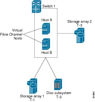
In conjunction with presenting Fibre Channel targets to iSCSI hosts, the IPS module presents each iSCSI host as a Fibre Channel host (in transparent mode), i.e. Host Bus Adaptor (HBA) to the Fibre Channel storage device. The storage device responds to each IP host as if it were a Fibre Channel host connected to the Fibre Channel network.
Figure 24-21 Fibre Channel SAN View
Refer to the IETF standards for IP storage at http://www.ietf.org, for information on the iSCSI protocol.
Enabling iSCSI
To begin configuring the iSCSI feature, you must explicitly enable iSCSI on the required switches in the fabric. By default, this feature is disabled in all switches in the Cisco MDS 9000 Family.
The configuration and verification commands for the iSCSI feature are only available when iSCSI is enabled on a switch. When you disable this feature, all related configurations are automatically discarded.
To enable iSCSI on a switch using Fabric Manager, follow these steps:
Step 1
Step 2
Step 3
Step 4
Using the iSCSI Wizard
To use the iSCSI wizard in Fabric Manager, follow these steps:
Step 1
Step 2
Step 3
Step 4
Step 5
Step 6
Routing iSCSI Requests and Responses
The iSCSI feature consists of routing iSCSI requests and responses between hosts in an IP network and Fibre Channel storage devices in the Fibre Channel SAN that are accessible from any Fibre Channel interface of the Cisco MDS 9000 Family switch.
Each iSCSI host that requires access to storage via the IPS module needs to have a compatible iSCSI driver installed. (The CCO website at provides a list of compatible drivers). Using iSCSI protocol, the iSCSI driver allows an iSCSI host to transport SCSI requests and responses over an IP network. From the host operating system perspective, the iSCSI driver appears to be a SCSI transport driver similar to a Fibre Channel driver for a peripheral channel in the host. From the storage device perspective, each IP host appears as a Fibre Channel host.
Routing SCSI from the IP host to the Fibre Channel storage device consists of the following main actions.
•
•
•
FCP (the Fibre Channel equivalent of iSCSI) carries SCSI commands over a Fibre Channel SAN.
Presenting Fibre Channel Targets as iSCSI Targets
The IPS module presents physical Fibre Channel targets as iSCSI targets allowing them to be accessed by iSCSI hosts. It does this in one of two ways:
•
•
The IPS module does not import Fibre Channel targets to iSCSI by default. Either dynamic or static mapping must be configured before the IPS module makes Fibre Channel targets available to iSCSI initiators. When both are configured, statically mapped Fibre Channel targets have a configured name. Targets that are not statically imported are advertised with the name created by the conventions explained in this section.
Dynamic Importing
To enable dynamic importing of Fibre Channel targets into iSCSI, use the iscsi import target fc command.
The IPS module maps each physical Fibre Channel target port as one iSCSI target. That is, all LU accessible via the physical storage target port are available as iSCSI LUs with the same LU number (LUN) as in the storage target.
For example, if an iSCSI target was created for Fibre Channel target port with pWWN 31:00:11:22:33:44:55:66 and that pWWN contains LUN 0 through 2, those LUNs would become available to an IP host as LUNs 0 through 2 as well.
If you have configured a switch name, then the switch name will be used instead of the management IP address. If you have not configured a switch name, the management IP address will be used.
The iSCSI target node name is created automatically using the iSCSI qualified name (IQN) format. The iSCSI qualified name is restricted to a maximum name length of 223 alphanumeric characters and a minimum length of 16 characters.
The IPS module creates an IQN formatted iSCSI node name using the following conventions:
•
iqn.1987-05.com.cisco:05.<mgmt-ip-address>.<slot#>-<port#>-<sub-intf#>.<Target-pWWN>•
iqn.1987-05.com.cisco:05.vrrp-<vrrp-ID#>-<vrrp-IP-addr>.<Target-pWWN>•
iqn.1987-02.com.cisco:05.<mgmt-ip-address>.pc-<port-ch-sub-intf#>.<Target-pWWN>With this format, each IPS port in a Cisco MDS 9000 Family switch creates a different iSCSI target node name for the same Fibre Channel target.
Configuring Dynamic Importing with Device Manager
To dynamically import Fibre Channel targets as iSCSI targets, follow these steps:
Step 1
Step 2
Step 3
Step 4
Static Importing
You can manually (statically) create an iSCSI target and assign a node name to it. A statically-mapped iSCSI target can either contain the whole FC target port, or it can contain one or more LUs from a Fibre Channel target port.
To create a static iSCSI virtual target for the Fibre Channel target port, follow these steps
Step 1
Step 2
Step 3
Step 4
Step 5
Step 6
Step 7
Step 8
For multiple interfaces configured with iSNS, a different static virtual target name has to be created for each interface tagged to an iSNS profile and each static virtual target must be advertised only from one interface.
Advertising iSCSI Targets
You can limit the Gigabit Ethernet interfaces over which static iSCSI targets are advertised. By default iSCSI targets are advertised on all Gigabit Ethernet interfaces, subinterfaces, PortChannel interfaces, and PortChannel subinterfaces.
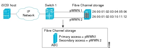
High Availability Static Target Importing
Statically imported iSCSI targets have an additional option to provide a secondary pWWN for the Fibre Channel target. This can be used when the physical Fibre Channel target is configured to have an LU visible across redundant ports. When the active port fails, the secondary port becomes active and the iSCSI session switches to use the new active port (see Figure 24-22).
Figure 24-22 Static Target Importing Through Two Fibre Channel Ports
In Figure 24-22, you can create a virtual iSCSI target that is mapped to both pWWN1 and pWWN2 to provide redundant access to the Fibre Channel targets.
The failover to secondary port is done transparently by the IPS port without impacting the iSCSI session from the host. All outstanding I/O are terminated with a check condition status when the primary port fails. New I/O received while the failover has not completed will receive a busy status.
Tip
Refer to the Cisco MDS 9000 Family Configuration Guide for details on setting the secondary pWWN.
Enable the revert to primary port option to direct the IPS port to switch back to the primary port when the primary port is up again. If this option is disabled (default) and the primary port is up again after a switchover, the old sessions will remain with the secondary port and does not switch back to the primary port. However, any new session will use the primary port. This is the only situation when both the primary and secondary ports are used at the same time.
To enable the revert to primary port option, follow these steps:
Step 1
Step 2
Step 3
Step 4
Step 5
Configuring the Trespass Feature
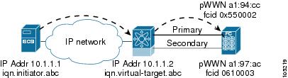
In addition to the high availability of statically imported iSCSI targets, the trespass feature is available (effective Release 1.3(x)) to enable the export of LUs, on an active port failure, from the active to the passive port of a statically imported iSCSI target.
In physical Fibre Channel targets, which are configured to have LUs visible over two Fibre Channel N-ports, when the active port fails, the passive port takes over. Some physical Fibre Channel targets require that the trespass command be issued, to export the LUs from the active port to the passive port. A statically imported iSCSI target's secondary pWWN option and an additional option of enabling the trespass feature is available for a physical Fibre Channel target with redundant ports. When the active port fails, the passive port becomes active, and if the trespass feature is enabled, the MDS issues a trespass command to the target to export the LUs on the new active port. The iSCSI session switches to use the new active port and the exported LUs are accessed over the new active port.
Figure 24-23 Virtual Target with an Active Primary Port
To configure the trespass feature, follow these steps:
Step 1
Step 2
Step 3
Step 4
iSCSI Virtual Target Configuration Examples
This section provides three examples of virtual target configurations.
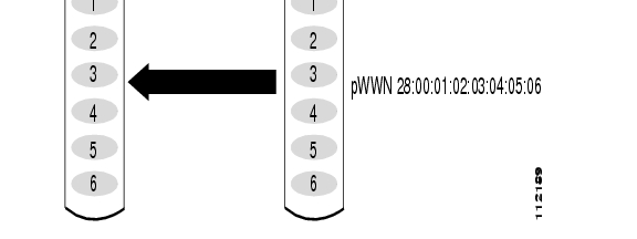
Example 1
This example assigns the whole Fibre Channel target as a virtual iSCSI target. All LUNs that are part of the Fibre Channel target are available as part of the iSCSI target.
Figure 24-24 Assigning iSCSI Node Names
Example 2
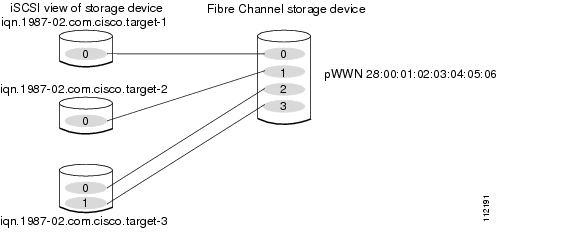
This example maps a subset of LUNs of a Fibre Channel target to three iSCSI virtual targets. Each iSCSI target only has one LUN.
Figure 24-25 Mapping LUNs to iSCSI a Node Name
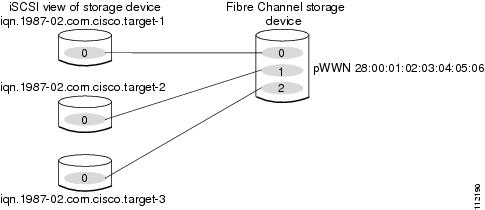
Example 3
This example maps three subsets of Fibre Channel LUN targets to three iSCSI virtual targets. Two iSCSI targets have one LUN and the third iSCSI target has two LUNs.
Figure 24-26 Mapping LUNs to Multiple iSCSI Node Names
Presenting iSCSI Hosts as Virtual Fibre Channel Hosts
The iSCSI hosts are mapped to virtual Fibre Channel hosts in one of two ways:
•
•
Dynamic Mapping
When an iSCSI host connects to the IPS module using the iSCSI protocol, a virtual N port is created for the host. The nWWNs and pWWNs are dynamically allocated from the switch Fibre Channel WWN pool. The IPS module registers this N port in the Fibre Channel SAN. The IPS module continues using that nWWN and pWWN to represent this iSCSI host until it no longer has a connection to any iSCSI target via that IP storage port.
At that point, the virtual Fibre Channel host is taken offline from the Fibre Channel SAN and the nWWNs and pWWNs are released back to the switch's Fibre Channel WWN pool. These addresses becomes available for assignment to other iSCSI hosts requiring access to Fibre Channel SANs.
When a dynamically mapped iSCSI initiator has multiple sessions to multiple Fibre Channel targets, each session can use the same pWWN and nWWN as long as it uses the same node name in the iSCSI login message.
Identifying Initiators
An iSCSI initiator is identified in one of two ways:
•
•
By default, the switch uses the iSCSI node name to identify the initiator.
Static Mapping
With dynamic mapping, each time the iSCSI host connects to the IPS module a new Fibre Channel N port is created and the nWWNs and pWWNs allocated for this N port may be different. Use the static mapping method to obtain the same nWWN and pWWNs for the iSCSI host each time it connects to the IPS module.
You can implement static mapping in one of two ways: system assignment or manual assignment.
•
•
Tip
Static mapping can be used on the IPS module to access intelligent Fibre Channel storage arrays that have access control and LUN mapping/masking configuration based on the initiator's pWWNs and/or nWWNs.
If an iSCSI host connects to multiple IPS ports, each port independently creates one virtual N port for the host. If static mapping is used, enough pWWNs should be configured for as many IPS ports to which a host connects.
If a system assignment option is used to configure WWNs for an iSCSI initiator, when the configuration is backed up to an ASCII file the system-assigned WWNs are also saved. Subsequently if you issue a CLI write erase command, you must manually delete the WWN configuration from the ASCII file.
Making the Dynamic Initiator WWN Mapping Static
After a dynamic initiator has already logged in, you may decide to permanently keep the automatically-assigned nWWN/pWWN mapping, so this initiator uses the same mapping the next time it logs in.
Assigning VSAN Membership to iSCSI Hosts
By default, a host is only in VSAN 1 (default VSAN). You can configure an iSCSI host to be a member of one or more VSANs. The IPS module creates one Fibre Channel virtual N port in each VSAN to which the host belongs.
When an initiator is configured in any other VSAN (other than VSAN 1), for example VSAN 2, the initiator is automatically removed from VSAN 1. If you also want it to be present in VSAN 1, you must explicitly configure the initiator in VSAN 1.
Assigning VSANs to a iSCSI Interface
All dynamic iSCSI initiators are members of VSAN 1. The port VSAN of an iSCSI interface is the default VSAN for all dynamic iSCSI initiators. The default port VSAN of an iSCSI interface is VSAN 1, but can be changed. All dynamic iSCSI initiators are member of the port VSAN of the iSCSI interface.
Tip
To modify the VSANs assigned to an iSCSI interface using Device Manager, follow these steps:
Step 1
Step 2
Step 3
Step 4
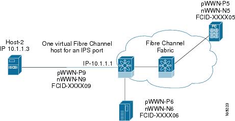
Configuring iSCSI Proxy Initiators
When an interface is in the proxy initiator mode, you can only configure Fibre Channel access control (zoning) based on the Fibre Channel interface attributes--the WWN pair and available FCIDs. You cannot configure zoning using iSCSI attributes such as the IP address or the iQN name of the iSCSI initiator. To enforce initiator-based access control, use iSCSI based access control.
By default, each iSCSI initiator appears as one Fibre Channel initiator in transparent mode in the Fibre Channel fabric. For some storage arrays, this appearance requires the initiator's pWWN to be manually configured for access control purposes. This process can be quite cumbersome. The Proxy initiator feature allows all iSCSI initiators to connect through one IPS port making it appear as one Fibre Channel port per VSAN. It simplifies the task of configuring the pWWN for each new initiator on the storage array, and Fibre Channel access control such as zoning. This feature along with static target importing (using LUN mapping) results in the configuration being performed only on the switch when a new iSCSI host is added. On the storage array, all LUNs that will be used by iSCSI initiators are configured to allow access by the proxy initiator's pWWN. From the iSCSI perspective, this configuration is no different from the default mode.
Figure 24-27 The iSCSI View of a Proxy Initiator
From the Fibre Channel perspective, only one Fibre Channel initiator is visible per VSAN.
Figure 24-28 The FC View with a Proxy Initiator
Configuring the iSCSI Proxy Initiator
To configure the proxy initiator, follow these steps:
Step 1
Step 2
Step 3
Step 4
Access Control in iSCSI
You can control access to each statically-mapped iSCSI target by specifying a list of IPS ports on which it will be advertised and specifying a list of iSCSI initiator node names allowed to access it. Fibre Channel zoning-based access control and iSCSI-based access control are the two mechanisms by which access control can be provided for iSCSI. Both methods can be used simultaneously.
This access control is in addition to the existing Fibre Channel access control. The iSCSI initiator has to be in the same VSAN and zone as the physical Fibre Channel target.
Fibre Channel Zoning-Based Access Control
Zoning is an access control mechanism within a VSAN. The switch zoning implementation extends the VSAN and zoning concepts from the Fibre Channel domain to also cover the iSCSI domain. This extension includes both iSCSI and Fibre Channel features and provides a uniform, flexible access control across a SAN. Static and dynamic are the two Fibre Channel zoning access control mechanisms.
•
•
To register an iSCSI host initiator as a member of a zone using Fabric Manager, follow these steps:
Step 1
Step 2
Step 3
Step 4
iSCSI-Based Access Control
For static iSCSI targets, you can manually configure a list of iSCSI initiators that are allowed to access it. The iSCSI initiator is identified by the iSCSI node name or the IP address of the iSCSI host.
By default, static virtual iSCSI targets are not accessible to any iSCSI host. You must explicitly configure accessibility to allow a virtual iSCSI target to be accessed by all hosts. The initiator access list can contain one or more initiators. Each initiator is identified by one of the following:
•
•
•
Enforcing Access Control
IPS modules use both iSCSI node name-based and Fibre Channel zoning-based access control lists to enforce access control during iSCSI discovery and iSCSI session creation.
•
•
The IPS module, then creates a Fibre Channel virtual N port (the N port may already exist) for this IP host and does a Fibre Channel name server query for the FCID of the Fibre Channel target pWWN that is being accessed by the IP host. It uses the IP host virtual N port's pWWN as the requester of the name server query. Thus, the name server does a zone-enforced query for the pWWN and responds to the query.
If the FCID is returned by the name server, then the iSCSI session is accepted. Otherwise, the login request is rejected.
iSCSI User Authentication
The IPS module supports the iSCSI authentication mechanism to authenticate iSCSI hosts that request access to storage. When iSCSI authentication is enabled, the iSCSI hosts must provide user name and password information each time an iSCSI session is established.
Only the Challenge Handshake Authentication Protocol (CHAP) authentication method is supported.If no authentication is configured, local authentication is used. You can use RADIUS authentication or TACACS+ authentication.
Configuring an Authentication Mechanism
During an iSCSI login, both the iSCSI initiator and target have the option to authenticate each other. By default, the IPS module allows either CHAP authentication or no authentication from iSCSI hosts.
Note
To configure an authentication method for iSCSI, follow these steps:
Step 1
Step 2
Step 3
From Device manager, check the Chap check box to configure DH-CHAP authentication, or check the none check box for no authentication.
Step 4
Configuring an iSCSI RADIUS Server
To configure an iSCSI RADIUS server, follow these steps:
Step 1
Step 2
Step 3
Advanced iSCSI Configuration
Advanced configuration options are available for iSCSI interfaces on a per-IPS port basis. These configurations are similar to the advanced FCIP configurations and are already explained in that section.
Cisco MDS switches support the following advanced features for iSCSI interfaces:
•
•
–
–
•
•
Setting the QOS Values
To set the QoS values, follow these steps:
Step 1
Step 2
Step 3
Step 4
iSCSI Forwarding Mode
The iSCSI gateway on the IPS module has two modes of forwarding operation
•
•
iSCSI High Availability
The following high availability features are available for iSCSI configurations:
•
•
•
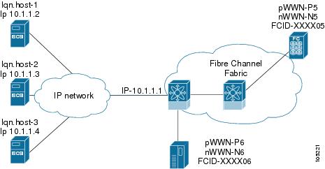
Multiple IPS Ports Connected to the Same IP Network
Figure 24-29 provides an example of a configuration with multiple Gigabit Ethernet interfaces in the same IP network.
Figure 24-29 Multiple Gigabit Ethernet Interfaces in the Same IP Network
In Figure 24-29, each iSCSI host discovers two iSCSI targets for every physical Fibre Channel target (with different names). The multi-pathing software on the host provides load-balancing over both paths. If one Gigabit Ethernet interface fails, the host multi-pathing software is not affected because it can use the second path.
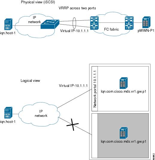
VRRP-Based High Availability
Figure 24-30 provides an example of a VRRP-based high availability iSCSI configuration.
Figure 24-30 VRRP-Based iSCSI High Availability
In Figure 24-30, each iSCSI host discovers one iSCSI target for every physical Fibre Channel target. When the Gigabit Ethernet interface of the VRRP master fails, the iSCSI session is terminated. The host then reconnects to the target and the session comes up because the second Gigabit Ethernet interface has taken over the virtual IP address as the new master.
Tip
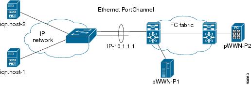
Ethernet PortChannel-Based High Availability
All iSCSI data traffic for one iSCSI link is carried on one TCP connection. Consequently, the aggregated bandwidth will be one Gbps for that iSCSI link.
Figure 24-31 provides a sample Ethernet PortChannel-based high availability iSCSI configuration.
Figure 24-31 Ethernet PortChannel-Based iSCSI High Availability
In Figure 24-31, each iSCSI host discovers one iSCSI target for every physical Fibre Channel target. The iSCSI session from the iSCSI host to the virtual iSCSI target (on the IPS port) uses one of the two physical interfaces (because an iSCSI session uses one TCP connection). When the Gigabit Ethernet interface fails, the IPS module and the Ethernet switch transparently forwards all the frames on to the second Gigabit Ethernet interface.
iSCSI Authentication Setup Guidelines
This section provides guidelines on iSCSI authentication possibilities, setup requirements, and sample scenarios.
This section does not specify the steps to enter or exit EXEC mode, configuration mode, or any submode. Be sure to verify the prompt before issuing any command.
Configuring Storage Name Services
Effective Release 1.3(1), the Internet Storage Name Service (iSNS) client feature is available in all switches in the Cisco MDS 9000 Family with IPS modules installed.
iSNS services allow your existing TCP/IP networks to function more effectively as storage area networks by automating the discover and management of iSCSI devices. To facilitate these functions, the iSNS client functionality registers iSCSI portals and all targets accessible through a particular interface with an external iSNS server.
Creating iSNS Profiles and Tagging Profiles
The iSNS client functionality on each interface (Gigabit Ethernet interface or subinterface or PortChannel) registers information with its configured iSNS server using an iSNS profile. This process is referred to as tagging an iSNS profile to an interface. Each iSNS profile keeps information about an iSNS server IP address. One profile can be tagged to one or more interfaces.
Once a profile is tagged to an interface, the MDS switch opens a TCP connection to the iSNS server IP address (using a well-known iSNS port number 3205) in the profile and registers network entity and portal objects. It goes through the FC name server database and configuration to find storage nodes to register with the server.
Statically-mapped virtual target is registered if the associated Fibre channel pWWN is present in the FC name server database and no access control configuration prevents it. A dynamically-mapped target is registered if the dynamic target importing is enabled.
A storage node is deregistered from the iSNS server when it becomes unavailable either because of configuration change (such as access control change or dynamic import disabling) or when the Fibre Channel storage port goes off-line. It will be registered again when the node is online.
When the iSNS client is unable to register/deregister objects with the iSNS server (e.g. as in unable to make a tcp connection to the iSNS server) it retries every minute to re-registers all iSNS objects for the affected interface(s) with the iSNS server.
Untagging a profile causes the network entity and portal to deregister from that interface.
Creating an iSNS Profile
To create an iSNS profile, follow these steps:
Step 1
Step 2
Step 3
Step 4
Modifying an iSNS Profile
To modify (tag) the iSNS profile for an interface, untag the interface from currently tagged iSNS profile and then tag to a new iSNS profile.
To tag an interface to a profile using Device Manager, follow these steps:
Step 1
Step 2
Step 3
Step 4
Default IP Storage Settings
Table 24-1 lists the default settings for Gigabit Ethernet parameters.
Table 24-1 Default Gigabit Ethernet Parameters
IP MTU frame size
1500 bytes for all Ethernet ports
Table 24-2 lists the default settings for FCIP parameters.
Table 24-3 lists the default settings for iSCSI parameters.
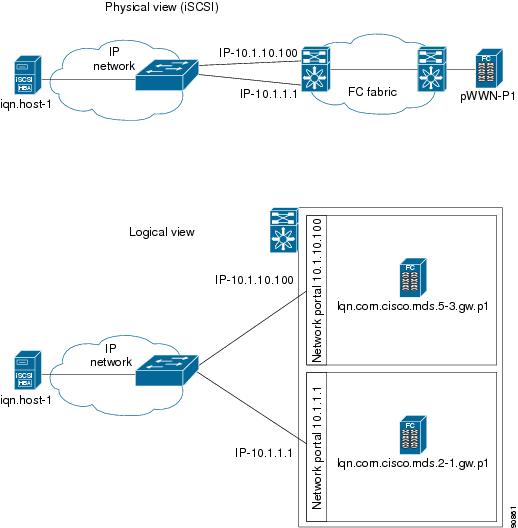
Using the IP Filter Wizard
Use the IP Filter Wizard to manage IP filters.
Step 1
Figure 24-32 IP Filter Wizard
The IP Filter Wizard is displayed.
Step 2
Creating IP Profiles
To create an IP profile, perform the following steps.
Step 1
Step 2
Step 3
Step 4
Step 5
Step 6
You see the newly created profile in the list of profiles.
Step 7
Adding IP Filters to Profiles
To add an IP filter to a profile, perform the following steps.
Step 1
Step 2
Step 3
Step 4
Step 5
Step 6
Step 7
You see the newly created filter in the list of filters.
Step 8
Step 9
Associating IP Profiles to Interfaces
To associate the profile to an interface, perform the following steps.
Step 1
Step 2
Step 3
Step 4
Step 5
Step 6
Step 7
Step 8
You see the newly associated profile in the list of profiles.
Step 9
Deleting IP Profiles
To delete an IP profile, perform the following steps.
Step 1
Step 2
Step 3
Step 4
Deleting IP Filters
To delete an IP filter, perform the following steps.
Step 1
Step 2
Step 3
Step 4