To verify the co-routed LSP, use the show mpls traffic-eng tunnels detail command.
Router# show mpls traffic-eng tunnels 7001 detail
Name: tunnel-te7001 Destination: 104.0.0.1 Ifhandle:0x8000aa4
Signalled-Name: Cisco8K-R11_t7001
Status:
Admin: up Oper: up (Uptime 136y10w)
path option 1, type explicit path01 (Basis for Setup, path weight 30 (reverse 30))
Protected-by PO index: 2
path option 2, type explicit path02 (Basis for Standby, path weight 100010 (reverse 100010))
Protected-by PO index: 1
G-PID: 0x0800 (derived from egress interface properties)
Bandwidth Requested: 10 kbps CT0
Creation Time: Wed Jan 11 03:08:36 2017 (136y10w ago)
Config Parameters:
Bandwidth: 10 kbps (CT0) Priority: 7 7 Affinity: 0x0/0xffff
Metric Type: TE (interface)
Path Selection:
Tiebreaker: Min-fill (default)
Hop-limit: disabled
Cost-limit: disabled
Path-invalidation timeout: 10000 msec (default), Action: Tear (default)
AutoRoute: disabled LockDown: disabled Policy class: not set
Forward class: 0 (default)
Forwarding-Adjacency: disabled
Autoroute Destinations: 0
Loadshare: 0 equal loadshares
Auto-bw: disabled
Fast Reroute: Disabled, Protection Desired: None
Path Protection: Enabled
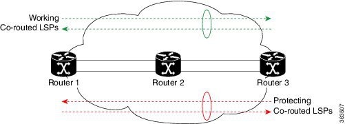
Association Type: Single Sided Bidirectional LSPs, Co-routed: YES
Association ID: 86, Source: 192.0.0.0
Reverse Bandwidth: 10 kbps (CT0), Standby: 10 kbps (CT0)
LSP Wrap Protection: Enabled
Reoptimization after affinity failure: Enabled
Soft Preemption: Disabled
Fault-OAM Info:
Last Fault Msg: Clear
SNMP Index: 25
Binding SID: None
Path Protection Info:
Standby Path: User defined [explicit path option: 2],
Last Switchover:
136y10w ago, From LSP 14 To LSP 16
No subcause recorded
Reopt time remaining: 0 seconds
Number of Switchovers 1, Standby Ready 3 times, Standby Reopt 0 times
Lockout Info:
Locked Out: NO
Locked out LSP ID: 0
Lockout Originated By: None
LSP Wrap Protection: Enabled
LSP Wrap Label: 24182
History:
Reopt. LSP:
Last Failure:
LSP not signalled, identical to the [CURRENT] LSP
Date/Time: Tue Jan 10 21:42:41 UTC 2017 [00:03:42 ago]
Standby Reopt LSP:
Last Failure:
LSP not signalled, identical to the [STANDBY] LSP
Date/Time: Tue Jan 10 21:42:41 UTC 2017 [00:03:42 ago]
First Destination Failed: 104.0.0.1
Prior LSP:
ID: 14 Path Option: 1
Removal Trigger: path protection switchover
Current LSP Info:
Instance: 18, Signaling Area: IS-IS 100 level-2
Uptime: 136y10w (since Wed Jan 11 03:09:56 UTC 2017)
Outgoing Interface: TenGigE0/4/0/2.1, Outgoing Label: 24157
Router-IDs: local 102.0.0.1
downstream 107.0.0.1
Soft Preemption: None
SRLGs: not collected
Path Info:
Outgoing:
Explicit Route:
Strict, 1.27.1.2
Strict, 3.67.1.2
Strict, 3.67.1.1
Strict, 1.46.1.2
Strict, 1.46.1.1
Strict, 104.0.0.1
Record Route: Disabled
Tspec: avg rate=10 kbits, burst=1000 bytes, peak rate=10 kbits
Session Attributes: Local Prot: Not Set, Node Prot: Not Set, BW Prot: Not Set
Soft Preemption Desired: Not Set
Reverse Associated LSP Information:
Signaled Name: Cisco8K-R10_t7001
Tunnel: 7001, Source: 104.0.0.1, Dest: 102.0.0.1, LSP: 9, State: Up
Association:
Association Type: Single Sided Bidirectional LSPs
Association ID: 86, Source: 192.0.0.0
Extended Association:
Global source: 0
Extended ID:
0x66000001 (102.0.0.1)
0x12 (0.0.0.18)
Protection:
Secondary (S): 0, Protecting (P): 0, Notification (N): 0, Oper (O): 0
Link Flags: Any, LSP Flags: 1:N Protection with Extra-Traffic
Reverse Tspec: avg rate=10 kbits, burst=1000 bytes, peak rate=10 kbits
Reverse ERO:
Explicit Route:
Strict, 1.46.1.1
Strict, 1.46.1.2
Strict, 3.67.1.1
Strict, 3.67.1.2
Strict, 1.27.1.2
Strict, 1.27.1.1
Strict, 102.0.0.1
Resv Info: None
Record Route: Disabled
Fspec: avg rate=10 kbits, burst=1000 bytes, peak rate=10 kbits
Standby LSP Info:
Instance: 19, Signaling Area: IS-IS 100 level-2
Uptime: 136y10w (since Wed Jan 11 03:10:04 UTC 2017), Oper State: Up
Outgoing Interface: TenGigE0/4/0/11.1, Outgoing Label: 24176
Router-IDs: local 102.0.0.1
downstream 109.0.0.1
Soft Preemption: None
SRLGs: not collected
Path Info:
Outgoing:
Explicit Route:
Strict, 1.29.1.2
Strict, 1.49.1.2
Strict, 1.49.1.1
Strict, 104.0.0.1
Record Route: Disabled
Tspec: avg rate=10 kbits, burst=1000 bytes, peak rate=10 kbits
Session Attributes: Local Prot: Not Set, Node Prot: Not Set, BW Prot: Not Set
Soft Preemption Desired: Not Set
Reverse Associated LSP Information:
Signaled Name: Cisco8K-R10_t7001
Tunnel: 7001, Source: 104.0.0.1, Dest: 102.0.0.1, LSP: 10, State: Up
Association:
Association Type: Single Sided Bidirectional LSPs
Association ID: 86, Source: 192.0.0.0
Extended Association:
Global source: 0
Extended ID:
0x68000001 (104.0.0.1)
0xa (0.0.0.10)
Protection:
Secondary (S): 0, Protecting (P): 1, Notification (N): 0, Oper (O): 0
Link Flags: Any, LSP Flags: 1:N Protection with Extra-Traffic
Resv Info: None
Record Route: Disabled
Fspec: avg rate=10 kbits, burst=1000 bytes, peak rate=10 kbits
Persistent Forwarding Statistics:
Out Bytes: 20272384
Out Packets: 79189
LSP Tunnel 104.0.0.1 7001 [9] is signalled, Signaling State: up
Tunnel Name: Cisco8K-R10_t7001 Tunnel Role: Tail
InLabel: TenGigE0/4/0/2.1, 24164
Signalling Info:
Src 104.0.0.1 Dst 102.0.0.1, Tun ID 7001, Tun Inst 9, Ext ID 104.0.0.1
Router-IDs: upstream 107.0.0.1
local 102.0.0.1
Bandwidth: 10 kbps (CT0) Priority: 7 7 DSTE-class: 0
Soft Preemption: None
SRLGs: not collected
Path Info:
Incoming Address: 1.27.1.1
Incoming:
Explicit Route:
Strict, 1.27.1.1
Strict, 102.0.0.1
Record Route: Disabled
Tspec: avg rate=10 kbits, burst=1000 bytes, peak rate=10 kbits
Session Attributes: Local Prot: Not Set, Node Prot: Not Set, BW Prot: Not Set
Soft Preemption Desired: Not Set
Reverse Associated LSP Information:
Signaled Name: Cisco8K-R11_t7001
Tunnel: 7001, Source: 102.0.0.1, Dest: 104.0.0.1, LSP: 18, State: Up
Association:
Association Type: Single Sided Bidirectional LSPs (Tie breaking slave)
Association ID: 86, Source: 192.0.0.0
Extended Association:
Global source: 0
Extended ID:
0x66000001 (102.0.0.1)
0x12 (0.0.0.18)
Protection:
Secondary (S): 0, Protecting (P): 0, Notification (N): 0, Oper (O): 0
Link Flags: Any, LSP Flags: 1:N Protection with Extra-Traffic
Resv Info: None
Record Route: Disabled
Fspec: avg rate=10 kbits, burst=1000 bytes, peak rate=10 kbits
LSP Tunnel 104.0.0.1 7001 [10] is signalled, Signaling State: up
Tunnel Name: Cisco8K-R10_t7001 Tunnel Role: Tail
InLabel: TenGigE0/4/0/11.1, 24463
Signalling Info:
Src 104.0.0.1 Dst 102.0.0.1, Tun ID 7001, Tun Inst 10, Ext ID 104.0.0.1
Router-IDs: upstream 109.0.0.1
local 102.0.0.1
Bandwidth: 10 kbps (CT0) Priority: 7 7 DSTE-class: 0
Soft Preemption: None
SRLGs: not collected
Path Info:
Incoming Address: 1.29.1.1
Incoming:
Explicit Route:
Strict, 1.29.1.1
Strict, 102.0.0.1
Record Route: Disabled
Tspec: avg rate=10 kbits, burst=1000 bytes, peak rate=10 kbits
Session Attributes: Local Prot: Not Set, Node Prot: Not Set, BW Prot: Not Set
Soft Preemption Desired: Not Set
Reverse Associated LSP Information:
Signaled Name: Cisco8K-R11_t7001
Tunnel: 7001, Source: 102.0.0.1, Dest: 104.0.0.1, LSP: 19, State: Up
Association:
Association Type: Single Sided Bidirectional LSPs (Tie breaking slave)
Association ID: 86, Source: 192.0.0.0
Extended Association: Fspec: avg rate=8K, burst=1K, peak rate=8K
To verify the forwarding interface, use the show mpls forwarding tunnels detail command.
Router# show mpls forwarding tunnels 7001 detail

Tunnel        Outgoing    Outgoing     Next Hop        Bytes
Name          Label       Interface                    Switched
------------- ----------- ------------ --------------- ------------
tt7001            24157       Te0/4/0/2.1  1.27.1.2        0
     Updated: Jan 10 21:40:04.966
     Version: 17852, Priority: 2
     Label Stack (Top -> Bottom): { 24157 }
     Local Label: 24354
     NHID: 0x0, Encap-ID: INVALID, Path idx: 0, Backup path idx: 0, Weight: 0
     MAC/Encaps: 18/22, MTU: 1500
     Packets Switched: 0

  Interface Name: tunnel-te7001, Interface Handle: 0x08000aa4, Local Label: 24354
  Forwarding Class: 0, Weight: 0
  Packets/Bytes Switched: 79189/20272384

 Feedback