- はじめに
- 製品の概要
- CLI
- スイッチ の初期設定
- Supervisor Engine 32 PISA の設定
- NSF with SSO スーパーバイザ エンジンの冗 長構成の設定
- RPR スーパーバイザ エンジンの冗長構成の設 定
- インターフェイスの設定
- レイヤ 2 スイッチング用 LAN ポートの設定
- Flex Link の設定
- EtherChannel の設定
- VLAN トランキング プロトコル(VTP)の設 定
- VLAN の設定
- プライベート VLAN の設定
- Cisco IP Phone サポートの設定
- IEEE 802.1Q トンネリングの設定
- レイヤ 2 プロトコル トンネリングの設定
- スパニング ツリー プロトコル(STP)および Multiple Spanning Tree(MST)の設定
- オプションのスパニングツリー プロトコル (STP)機能の設定
- レイヤ 3 インターフェイスの設定
- 単一方向イーサネット(UDE)および単一方 向リンク ルーティング(UDLR)の設定
- マルチプロトコル ラベル スイッチング (MPLS)の設定
- IPv4 マルチキャスト バーチャネル プライ ベート ネットワーク(MVPN)サポートの設 定
- IP ユニキャスト レイヤ 3 スイッチングの設定
- IPv6 マルチキャスト PFC3B レイヤ 3 スイッ チングの設定
- IPv4 マルチキャスト レイヤ 3 スイッチングの 設定
- IPv6 マルチキャスト トラフィック用の MLDv2 スヌーピングの設定
- IPv4 マルチキャスト トラフィック用 IGMP スヌーピングの設定
- PIM スヌーピングの設定
- RGMP の設定
- ネットワーク セキュリティの設定
- Cisco IOS ACL サポートの概要
- VLAN アクセス制御リスト(VACL) の設定
- DoS からの保護の設定
- DHCP スヌーピングの設定
- DAI の設定
- トラフィック ストーム制御の設定
- 不明なユニキャスト/マルチキャスト フラッ ディングのブロック(UUFB/UMFB)の設定
- PFC QoS の設定
- マルチプロトコル ラベル スイッチング (MPLS)QoS の設定
- PFC QoS 統計データ エクスポートの設定
- Network Admission Control(NAC)の設 定
- IEEE 802.1X ポートベースの認証の設定
- ポート セキュリティの設定
- CDP の設定
- 単一方向リンク検出(UDLD)の設定
- NetFlow データ エクスポート(NDE)の設 定
- NetFlow の設定
- ローカル スイッチド ポート アナライザ (SPAN)、Remote SPAN(RSPAN)、およ び Encapsulated RSPAN(ERSPAN) の設 定
- SNMP ifIndex の持続性の設定
- 電源管理および環境モニタ
- オンライン診断の設定
- Web Cache Communication Protocol (WCCP)による Web キャッシュ サービスの 設定
- Top-N レポートの使用方法
- レイヤ 2 traceroute ユーティリティの使用
- オンライン診断テスト
- 略語
- 索引
Catalyst Supervisor Engine 32 PISA Cisco IOS ソフトウェア コンフィギュレーション ガイド, 12.2ZY
偏向のない言語
この製品のマニュアルセットは、偏向のない言語を使用するように配慮されています。このマニュアルセットでの偏向のない言語とは、年齢、障害、性別、人種的アイデンティティ、民族的アイデンティティ、性的指向、社会経済的地位、およびインターセクショナリティに基づく差別を意味しない言語として定義されています。製品ソフトウェアのユーザーインターフェイスにハードコードされている言語、RFP のドキュメントに基づいて使用されている言語、または参照されているサードパーティ製品で使用されている言語によりドキュメントに例外が存在する場合があります。シスコのインクルーシブランゲージに対する取り組みの詳細は、こちらをご覧ください。
翻訳について
このドキュメントは、米国シスコ発行ドキュメントの参考和訳です。リンク情報につきましては、日本語版掲載時点で、英語版にアップデートがあり、リンク先のページが移動/変更されている場合がありますことをご了承ください。あくまでも参考和訳となりますので、正式な内容については米国サイトのドキュメントを参照ください。
- Updated:
- 2017年7月28日
章のタイトル: スパニング ツリー プロトコル(STP)および Multiple Spanning Tree(MST)の設定
スパニング ツリー プロトコル(STP)およびMultiple Spanning Tree(MST)の設定
この章では、Catalyst 6500 シリーズ スイッチに Spanning Tree Protocol(STP; スパニング ツリー プロトコル)および Multiple Spanning Tree(MST)プロトコルを設定する手順について説明します。

(注) この章で使用しているコマンドの構文および使用方法の詳細については、次の URL で『Catalyst Supervisor Engine 32 PISA Cisco IOS Command Reference, Release 12.2ZY』を参照してください。
http://www.cisco.com/en/US/docs/switches/lan/catalyst6500/ios/12.2ZY/command/reference/cmdref.html
•![]() 「IEEE 802.1w 高速スパニング ツリー プロトコル(RSTP)の機能概要」
「IEEE 802.1w 高速スパニング ツリー プロトコル(RSTP)の機能概要」
(注) PortFast、UplinkFast、および BackboneFast STP 拡張機能の設定手順については、第 18 章「オプションのスパニングツリー プロトコル(STP)機能の設定」を参照してください。
STP の機能概要
•![]() 「ブリッジ プロトコル データ ユニット(BPDU)の概要」
「ブリッジ プロトコル データ ユニット(BPDU)の概要」
STP の概要
STP は、ネットワークの不要なループを排除しながらパスの冗長性を提供する、レイヤ 2 リンク管理プロトコルです。レイヤ 2 イーサネット ネットワークが正常に動作するには、2 つのステーション間で存在できるアクティブ パスは 1 つだけです。STP の動作は透過的なので、エンド ステーションが単一の LAN セグメントに接続されているのか、それとも複数セグメントからなるスイッチド LAN に接続されているのかを、エンド ステーションが検知できません。
Catalyst 6500 シリーズ スイッチは、すべての Virtual LAN(VLAN; 仮想LAN)で STP(IEEE 802.1D ブリッジ プロトコル)を使用します。デフォルトでは、(STP を手動でディセーブルにしないかぎり)設定されている VLAN ごとに 1 つの STP インスタンスが動作します。STP は、VLAN 単位でイネーブルおよびディセーブルにすることができます。
フォールトトレラントなインターネットワークを作成する場合、ネットワーク上のすべてのノード間にループフリー パスを形成する必要があります。STP アルゴリズムは、スイッチド レイヤ 2 ネットワーク上で最良のループフリー パスを算出します。レイヤ 2 LAN ポートは定期的に STP フレームを送受信します。ネットワーク装置はこれらのフレームを転送しないで、フレームを使用してループフリー パスを構築します。
エンド ステーション間に複数のアクティブ パスがあると、ネットワーク内でループが発生する原因になります。ネットワークにループが存在する場合、エンド ステーションが重複したメッセージを受信したり、ネットワーク装置が複数のレイヤ 2 LAN ポート上のエンド ステーション Media Access Control(MAC; メディア アクセス制御)アドレスを学習したりする可能性があります。このような状況が、不安定なネットワーク環境につながります。
STP は、ルート ブリッジおよびそのルートからレイヤ 2 ネットワーク上のすべてのネットワーク装置へのループフリー パスを備えたツリーを定義します。STP は冗長データ パスを強制的にスタンバイ(ブロック)ステートにします。スパニング ツリーの 1 つのネットワーク セグメントで障害が発生し、冗長パスが存在する場合、STP アルゴリズムはスパニング ツリー トポロジを再計算し、スタンバイ パスをアクティブにします。
ネットワーク装置上の 2 つのレイヤ 2 LAN ポートがループの一部になっている場合、どちらのポートがフォワーディング ステートになり、どちらのポートがブロッキング ステートになるかは、STP ポート プライオリティおよびポート パス コストの設定によって決まります。STP ポート プライオリティ値は、ネットワーク トポロジにおけるポートの位置を表すとともに、ポートがトラフィックを渡すのに適した位置にあるかどうかを表します。STP ポート パス コスト値は、メディア速度を表します。
ブリッジ ID の概要
各ネットワーク装置上の各 VLAN には、一意の 64 ビット ブリッジ ID が設定されています。ブリッジ ID はブリッジ プライオリティ値、拡張システム ID、および STP MAC アドレス割り当てで構成されています。
ブリッジ プライオリティ値
(注) Catalyst 6500 シリーズ スイッチでは、拡張システム ID は常につねにイネーブルです。
拡張システム ID がイネーブルの場合、ブリッジ プライオリティは 4 ビット値です(表 17-1 および「VLAN のブリッジ プライオリティの設定」を参照)。
拡張システム ID
12 ビットの拡張システム ID フィールドはブリッジ ID の一部です(表 17-1 を参照)。Catalyst 6500 シリーズ スイッチ は 64 の MAC アドレスがあり、必ず 12 ビットの拡張システム ID を使用します。
|
|
|
||||||||||||||
|---|---|---|---|---|---|---|---|---|---|---|---|---|---|---|---|
|
|
|
|
|
|
|
|
|
|
|
|
|
|
|
|
|
STP MAC アドレスの割り当て
Catalyst 6500 シリーズ スイッチには、STP などのソフトウェア機能をサポートするために使用できるアドレスが 64 あります。MAC アドレスの範囲を表示するには、 show catalyst6000 chassis-mac-address コマンドを入力します。
STP では拡張システム ID とともに MAC アドレスを使用して、VLAN ごとにブリッジ ID が重複しないようにします。
いずれかの装置で MAC アドレス リダクションがイネーブルになっている場合、望ましくないルート ブリッジ選択やスパニング ツリー トポロジ問題を回避するために、レイヤ 2 で接続されているその他すべてのネットワーク装置でも、MAC アドレス リダクションをイネーブルにする必要があります。
MAC アドレス リダクションがイネーブルの場合、ルート ブリッジのプライオリティは、4096 の倍数プラス VLAN ID になります。MAC アドレス リダクションがイネーブルの場合、スイッチのブリッジ ID(ルート ブリッジの ID を決定するためスパニング ツリー アルゴリズムによって使用され、最小値のほうが優先される)は、4096 の倍数になるようにしか指定できません。次の数値に限り利用可能です。0、4096、8192、12288、16384、20480、24576、28672、32768、36864、40960、45056、49152、53248、57344、および 61440。
同じスパニング ツリー ドメイン内の別のブリッジが MAC アドレス リダクション機能を実行しない場合、ブリッジ ID の選択がより細かい粒度のために、そのブリッジがルート ブリッジの所有権を取得する可能性があります。
ブリッジ プロトコル データ ユニット(BPDU)の概要
Bridge Protocol Data Unit(BPDU; ブリッジ プロトコル データ ユニット)はルート ブリッジから一方向に送信されます。各ネットワーク装置はコンフィギュレーション BPDU を送信して、スパニング ツリー トポロジを伝達および計算します。各コンフィギュレーション BPDU に含まれる最小限の情報は、次のとおりです。
•![]() 送信側ネットワーク装置がルート ブリッジと見なしているネットワーク装置の固有のブリッジ ID
送信側ネットワーク装置がルート ブリッジと見なしているネットワーク装置の固有のブリッジ ID
•![]() hello タイマー、転送遅延タイマー、および max-age プロトコル タイマーの値
hello タイマー、転送遅延タイマー、および max-age プロトコル タイマーの値
ネットワーク装置が BPDU フレームを伝送すると、そのフレームが伝送される LAN に接続されたすべてのネットワーク装置が BPDU を受信します。ネットワーク装置が BPDU を受信すると、スイッチはそのフレームを転送するのではなく、フレームに含まれる情報を使用して BPDU を計算し、トポロジに変更があれば、BPDU の送信を開始します。
•![]() 1 台のネットワーク装置がルート ブリッジとして選定されます。
1 台のネットワーク装置がルート ブリッジとして選定されます。
•![]() パス コストに基づいて、各ネットワーク装置のルート ブリッジまでの最短距離が計算されます。
パス コストに基づいて、各ネットワーク装置のルート ブリッジまでの最短距離が計算されます。
•![]() LAN セグメントごとに指定ブリッジが選択されます。これはルート ブリッジに最も近いネットワーク装置であり、このネットワーク装置を経由してルートにフレームが転送されます。
LAN セグメントごとに指定ブリッジが選択されます。これはルート ブリッジに最も近いネットワーク装置であり、このネットワーク装置を経由してルートにフレームが転送されます。
ルート ブリッジの選定
VLAN ごとに、最高のブリッジ ID(数値的に最小の ID 値)を持つネットワーク装置がルート ブリッジとして選定されます。すべてのネットワーク装置がデフォルト プライオリティ(32768)に設定されている場合は、VLAN 内で最小の MAC アドレスを持つネットワーク装置がルート ブリッジになります。ブリッジ プライオリティ値はブリッジ ID の最上位ビットを占めます。
ブリッジ プライオリティ値を変更すると、スイッチがルート ブリッジとして選定される確率が変わります。大きな値を設定するとその確率が高くなり、小さな値を設定すると低くなります。
STP ルート ブリッジは、レイヤ 2 ネットワークにおけるスパニング ツリー トポロジの論理上の中心です。レイヤ 2 ネットワーク内のどの場所からも、ルート ブリッジに到達するために必要とされないパスは、すべて STP ブロッキング モードになります。
BPDU には、送信側ブリッジおよびそのポートについて、ブリッジおよび MAC アドレス、ブリッジ プライオリティ、ポート プライオリティ、パス コストなどの情報が含まれます。STP はこの情報を使用してレイヤ 2 ネットワークのルート ブリッジを選定し、ルート ブリッジへのルート ポートを選定し、各レイヤ 2 セグメントの指定ポートを判別します。
STP プロトコル タイマー
表 17-2 に、STP のパフォーマンスに影響する STP プロトコル タイマーを示します。
|
|
|
|---|---|
スパニング ツリー トポロジの作成
図 17-1 では、スイッチ A がルート ブリッジに選定されます。これは、すべてのネットワーク装置でブリッジ プライオリティがデフォルト(32768)に設定されており、スイッチ A の MAC アドレスが最小であるためです。ただし、トラフィック パターン、転送ポートの数、またはリンク タイプによっては、スイッチ A が最適なルート ブリッジであるとは限りません。最適なネットワーク装置がルート ブリッジになるように、装置のプライオリティを上げる(数値を下げる)ことで、ルートとして最適なネットワーク装置を使用する、新しい STP トポロジを強制的に再計算させることができます。
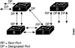
スパニング ツリー トポロジをデフォルトのパラメータに基づいて計算すると、スイッチド ネットワーク上の送信元から宛先エンド ステーションまでのパスが最適にならない可能性があります。たとえば、現在のルート ポートよりも数値の大きいポートに高速リンクを接続すると、ルート ポートが変更される場合があります。最高速のリンクをルート ポートにすることが重要です。
たとえば、スイッチ B の 1 つのポートが光ファイバ リンクであり、同じスイッチの別のポート(Unshielded Twisted-Pair(UTP; シールドなしツイストペア)リンク)がルート ポートになっていると仮定します。ネットワーク トラフィックを高速の光ファイバ リンクに流した方が効率的です。光ファイバ ポートの STP ポート プライオリティをルート ポートよりも上げる(数値を下げる)と、光ファイバ ポートが新しいルート ポートになります。
STP ポート ステート
STP ポート ステートの概要
プロトコル情報がスイッチド LAN を通過するとき、伝播遅延が生じることがあります。その結果、スイッチド ネットワークのさまざまな時点および場所でトポロジの変化が発生します。レイヤ 2 LAN ポートがスパニング ツリー トポロジに含まれていない状態からフォワーディング ステートに直接移行すると、一時的にデータ ループが形成される可能性があります。ポートは新しいトポロジ情報がスイッチド LAN 経由で伝播されるまで待機し、それからフレーム転送を開始する必要があります。さらに、古いトポロジで転送されたフレームの存続時間を満了させることも必要です。
STP を使用する Catalyst 6500 シリーズ スイッチ上の各レイヤ 2 LAN ポートは、次の 5 種類のステートのいずれかになります。
•![]() ブロッキング:レイヤ 2 LAN ポートがフレーム転送に参加していない状態です。
ブロッキング:レイヤ 2 LAN ポートがフレーム転送に参加していない状態です。
•![]() リスニング:レイヤ 2 LAN ポートがフレーム転送に参加すべきであると STP が判断した場合に、ブロッキング ステートのあとで最初に開始する移行ステートです。
リスニング:レイヤ 2 LAN ポートがフレーム転送に参加すべきであると STP が判断した場合に、ブロッキング ステートのあとで最初に開始する移行ステートです。
•![]() ラーニング:レイヤ 2 LAN ポートがフレーム転送に参加する準備をしている状態です。
ラーニング:レイヤ 2 LAN ポートがフレーム転送に参加する準備をしている状態です。
•![]() フォワーディング:レイヤ 2 LAN ポートはフレームを転送します。
フォワーディング:レイヤ 2 LAN ポートはフレームを転送します。
•![]() ディセーブル:レイヤ 2 LAN ポートが STP に参加せず、フレームを転送していない状態です。
ディセーブル:レイヤ 2 LAN ポートが STP に参加せず、フレームを転送していない状態です。
レイヤ 2 LAN ポートは、次のように 5 種類のステートを移行します。
図 17-2図 17-2 に、レイヤ 2 LAN ポートがどのように 5 種類のステートを移行するかを示します。
図 17-2 レイヤ 2 LAN インターフェイス ステート
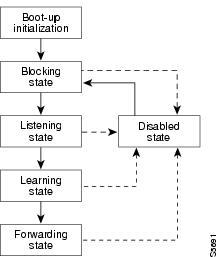
STP をイネーブルにすると、Catalyst 6500 シリーズ スイッチ、VLAN、およびネットワーク上の全てのポートは、電源投入時に必ずブロッキング ステートを経て、それからリスニングおよびラーニングという移行ステートに進みます。設定が適切であれば、各レイヤ 2 LAN ポートはフォワーディング ステートまたはブロッキング ステートで安定します。
STP アルゴリズムによってレイヤ 2 LAN ポートがフォワーディング ステートになると、次の処理が行われます。
1.![]() レイヤ 2 LAN ポートがリスニング ステートになり、ブロッキング ステートに移行するように指示するプロトコル情報を待ちます。
レイヤ 2 LAN ポートがリスニング ステートになり、ブロッキング ステートに移行するように指示するプロトコル情報を待ちます。
2.![]() レイヤ 2 LAN ポートが転送遅延タイマーの満了を待ち、その時点でラーニング ステートになり、転送遅延タイマーをリセットします。
レイヤ 2 LAN ポートが転送遅延タイマーの満了を待ち、その時点でラーニング ステートになり、転送遅延タイマーをリセットします。
3.![]() ラーニング ステートで、レイヤ 2 LAN ポートはフレーム転送を引き続きブロックしながら、転送データベースのエンド ステーションのロケーション情報を学習します。
ラーニング ステートで、レイヤ 2 LAN ポートはフレーム転送を引き続きブロックしながら、転送データベースのエンド ステーションのロケーション情報を学習します。
4.![]() レイヤ 2 LAN ポートは、転送遅延タイマーの終了とともにフォワーディング ステートになり、学習およびフレーム転送が両方ともイネーブルになります。
レイヤ 2 LAN ポートは、転送遅延タイマーの終了とともにフォワーディング ステートになり、学習およびフレーム転送が両方ともイネーブルになります。
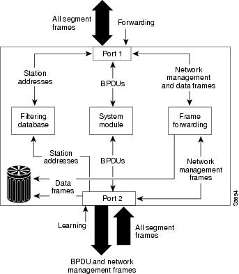
ブロッキング ステート
ブロッキング ステートのレイヤ 2 LAN ポートは、フレーム転送に参加しません(図 17-3 を参照)。初期化後、各レイヤ 2 LAN ポートに BPDU が送信されます。ネットワーク装置は、他のネットワーク装置と BPDU を交換するまでは、そのネットワーク装置をルートと見なします。この BPDU 交換により、ネットワーク上のどのネットワーク装置がルートまたはルート ブリッジであるかが確定します。ネットワークにネットワーク装置が 1 台しか存在しない場合は、BPDU 交換は行われず、転送遅延タイマーが終了し、ポートはリスニング ステートに移行します。初期化後、ポートは必ずブロッキング ステートになります。
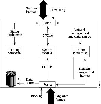
ブロッキング ステートのレイヤ 2 LAN ポートの動作は、次のとおりです。
•![]() 転送用に他のポートからスイッチングされたフレームを廃棄します。
転送用に他のポートからスイッチングされたフレームを廃棄します。
•![]() アドレス データベースに、エンド ステーションのロケーション情報は組み込みません (ブロッキング状態のレイヤ 2 LAN ポートに関する学習は行われないため、アドレス データベースは更新されません)。
アドレス データベースに、エンド ステーションのロケーション情報は組み込みません (ブロッキング状態のレイヤ 2 LAN ポートに関する学習は行われないため、アドレス データベースは更新されません)。
•![]() BPDU を受信し、それをシステム モジュールに転送します。
BPDU を受信し、それをシステム モジュールに転送します。
リスニング ステート
リスニング ステートは、レイヤ 2 LAN ポートがブロッキング ステートを経て最初に開始する移行ステートです。レイヤ 2 LAN ポートがフレーム転送に参加すべきであると STP が判断した場合に、レイヤ 2 LAN ポートはこのステートを開始します。図 17-4 に、リスニング ステートのレイヤ 2 LAN ポートを示します。
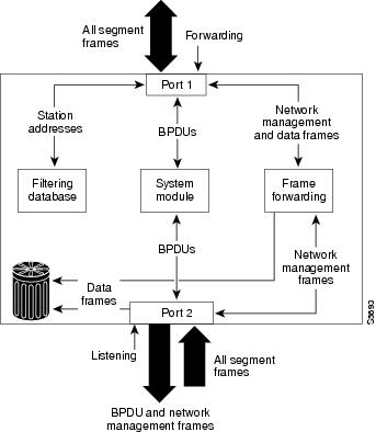
リスニング ステートのレイヤ 2 LAN ポートの動作は、次のとおりです。
•![]() 転送用に他の LAN ポートからスイッチングされたフレームを廃棄します。
転送用に他の LAN ポートからスイッチングされたフレームを廃棄します。
•![]() アドレス データベースに、エンド ステーションのロケーション情報は組み込みません (この時点で学習は行われないため、アドレス データベースは更新されません)。
アドレス データベースに、エンド ステーションのロケーション情報は組み込みません (この時点で学習は行われないため、アドレス データベースは更新されません)。
•![]() BPDU を受信し、それをシステム モジュールに転送します。
BPDU を受信し、それをシステム モジュールに転送します。
ラーニング ステート
ラーニング ステートのレイヤ 2 LAN ポートは、フレーム転送に参加するための準備を行います。レイヤ 2 LAN ポートは、リスニング ステートからラーニング ステートを開始します。図 17-5 に、リスニング ステートのレイヤ 2 LAN ポートを示します。
ラーニング ステートのレイヤ 2 LAN ポートの動作は、次のとおりです。
•![]() 転送用に他のポートからスイッチングされたフレームを廃棄します。
転送用に他のポートからスイッチングされたフレームを廃棄します。
•![]() エンド ステーションのロケーション情報をアドレス データベースに組み込みます。
エンド ステーションのロケーション情報をアドレス データベースに組み込みます。
•![]() BPDU を受信し、それをシステム モジュールに転送します。
BPDU を受信し、それをシステム モジュールに転送します。
フォワーディング ステート
フォワーディング ステートのレイヤ 2 LAN ポートは、フレームを転送します(図 17-6 を参照)。レイヤ 2 LAN ポートは、ラーニング ステートからフォワーディング ステートを開始します。
図 17-6 フォワーディング ステートのインターフェイス 2
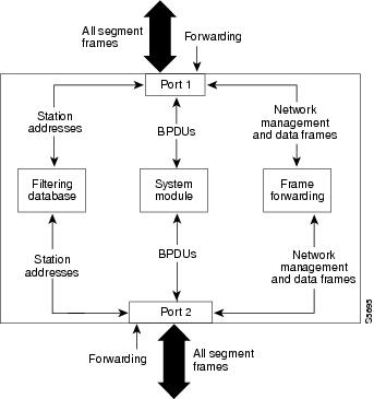
フォワーディング ステートのレイヤ 2 LAN ポートの動作は、次のとおりです。
•![]() 転送用に他のポートからスイッチングされたフレームを転送します。
転送用に他のポートからスイッチングされたフレームを転送します。
•![]() エンド ステーションのロケーション情報をアドレス データベースに組み込みます。
エンド ステーションのロケーション情報をアドレス データベースに組み込みます。
•![]() BPDU を受信し、それをシステム モジュールに転送します。
BPDU を受信し、それをシステム モジュールに転送します。
ディセーブル ステート
ディセーブル ステートのレイヤ 2 LAN ポートは、フレーム転送または STP に参加しません(図 17-7 を参照)。ディセーブル ステートのレイヤ 2 LAN ポートは事実上、動作することはありません。
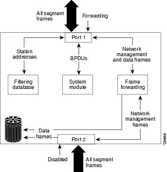
ディセーブル ステートのレイヤ 2 LAN ポートの動作は、次のとおりです。
•![]() 転送用に他のポートからスイッチングされたフレームを廃棄します。
転送用に他のポートからスイッチングされたフレームを廃棄します。
•![]() アドレス データベースに、エンド ステーションのロケーション情報は組み込みません (学習は行われないため、アドレス データベースは更新されません)。
アドレス データベースに、エンド ステーションのロケーション情報は組み込みません (学習は行われないため、アドレス データベースは更新されません)。
STP および IEEE 802.1Q トランク
802.1Q トランクによって、ネットワークの STP の構築方法に、いくつかの制約が課されます。802.1Q トランクを使用して接続しているシスコのネットワーク装置では、トランク上で許容される VLAN ごとに 1 つの STP インスタンスが維持されます。しかし、他社製の 802.1Q ネットワーク装置では、トランク上で許容されるすべての VLAN に対して 1 つの STP インスタンスしか維持されません。
802.1Q トランクを使用してシスコのネットワーク装置を他社製のネットワーク装置に接続する場合、シスコのネットワーク装置は、トランクの 802.1Q VLAN の STP インスタンスを、他社製の 802.1Q ネットワーク装置の STP インスタンスと統合します。ただし、VLAN 別の STP 情報はすべて、他社製の 802.1Q ネットワーク装置のクラウドと切り離されて、シスコのネットワーク装置によって維持されます。シスコのネットワーク装置を隔てている他社製の 802.1Q 装置のクラウドは、ネットワーク装置間の単一トランク リンクとして処理されます。
802.1Q トランクの詳細については、 第 8 章「レイヤ 2 スイッチング用 LAN ポートの設定」 を参照してください。
IEEE 802.1w 高速スパニング ツリー プロトコル(RSTP)の機能概要
Rapid Spanning Tree Protocol(RSTP; 高速スパニング ツリー プロトコル)は、ポイントツーポイント配線を利用してスパニング ツリーの高速コンバージェンスを実現します。スパニング ツリーの再設定は 1 秒以内に実行できます(802.1D スパニング ツリーのデフォルト設定の場合は 50 秒かかります)。
•![]() 「ブリッジ プロトコル データ ユニット(BPDU)の形式と処理」
「ブリッジ プロトコル データ ユニット(BPDU)の形式と処理」
•![]() 「Rapid Per-VLAN Spanning-Tree(Rapid PVST)」
「Rapid Per-VLAN Spanning-Tree(Rapid PVST)」
ポート ロールとアクティブ トポロジ
RSTP では、ポート ロールを割り当ててアクティブ トポロジを学習することで、スパニング ツリーの高速コンバージェンスを実現しています。スイッチで説明しているように、RSTP は、802.1D STP を構築して、最高のスイッチ プライオリティ(最小プライオリティ値)を持つ「ルート ブリッジの選定」をルート ブリッジとして選択します。次に RSTP は、各ポートに次のいずれか 1 つの役割を割り当てます。
•![]() ルート ポート:スイッチがルート ブリッジにパケットを転送する際に最適パス(最小コスト)を提供します。
ルート ポート:スイッチがルート ブリッジにパケットを転送する際に最適パス(最小コスト)を提供します。
•![]() 指定ポート:指定スイッチに接続します。LAN からルート ブリッジにパケットを転送する際に最小パス コストとなります。指定スイッチが LAN に接続されるポートを指定ポートと呼びます。
指定ポート:指定スイッチに接続します。LAN からルート ブリッジにパケットを転送する際に最小パス コストとなります。指定スイッチが LAN に接続されるポートを指定ポートと呼びます。
•![]() 代替ポート:現在のルート ポートが提供するルート ブリッジへの代替パスを提供します。
代替ポート:現在のルート ポートが提供するルート ブリッジへの代替パスを提供します。
•![]() バックアップ ポート:指定ポートが提供する、スパニング ツリーのリーフに向かうパスのバックアップとして機能します。バックアップ ポートは、2 つのポートがループバック内でポイントツーポイント リンクで接続されている場合、または 1 つのスイッチに共有 LAN セグメントへの接続が複数ある場合に限り、存在できます。
バックアップ ポート:指定ポートが提供する、スパニング ツリーのリーフに向かうパスのバックアップとして機能します。バックアップ ポートは、2 つのポートがループバック内でポイントツーポイント リンクで接続されている場合、または 1 つのスイッチに共有 LAN セグメントへの接続が複数ある場合に限り、存在できます。
•![]() ディセーブル ポート:スパニング ツリーの動作中の役割が指定されていないポートです。
ディセーブル ポート:スパニング ツリーの動作中の役割が指定されていないポートです。
ルート ポートまたは指定のポート ロールを割り当てられたポートは、アクティブ トポロジに含まれます。代替ポートまたはバックアップのポート ロールを割り当てられたポートは、アクティブ トポロジから除外されます。
ネットワーク全体で一貫したポート ロールがある安定したトポロジでは、RSTP により各ルート ポートおよび指定ポートは即座にフォワーディング ステートに移行し、すべての代替ポートおよびバックアップ ポートは必ず廃棄ステートになります(802.1D でのブロッキングと同様)。ポート ステートは、フォワーディングおよびラーニング プロセスの動作を制御します。 表 17-3 に、802.1D と RSTP ポート ステートの比較を示します。
|
|
|
|
ポートの有無 |
|---|---|---|---|
シスコの STP 実装製品との整合性をはかるために、このマニュアルではポートの 廃棄 ステートを ブロッキング と定義します。指定ポートは、リスニング ステートから開始します。
高速コンバージェンス
RSTP には、スイッチ、スイッチ ポート、または LAN に障害が発生したあとに、短時間で接続を回復する機能があります。エッジ ポート、新規ルート ポート、およびポイントツーポイント リンクで接続されたポートに対して、次のような高速コンバージェンス機能を提供します。
•![]() エッジ ポート: spanning-tree portfast インターフェイス コンフィギュレーション コマンドを使用して RSTP スイッチ にあるエッジ ポートとしてポートを設定した場合、エッジ ポートは即座にフォワーディング ステートに移行します。エッジ ポートは Port Fast 対応ポートと同じで、これをイネーブルにできるのは、単一のエンド ステーションに接続されているポートだけです。
エッジ ポート: spanning-tree portfast インターフェイス コンフィギュレーション コマンドを使用して RSTP スイッチ にあるエッジ ポートとしてポートを設定した場合、エッジ ポートは即座にフォワーディング ステートに移行します。エッジ ポートは Port Fast 対応ポートと同じで、これをイネーブルにできるのは、単一のエンド ステーションに接続されているポートだけです。
•![]() ルート ポート:RSTP が新規ルート ポートを選択した場合、古いルート ポートをブロックし即座に新規ルート ポートがフォワーディング ステートに移行します。
ルート ポート:RSTP が新規ルート ポートを選択した場合、古いルート ポートをブロックし即座に新規ルート ポートがフォワーディング ステートに移行します。
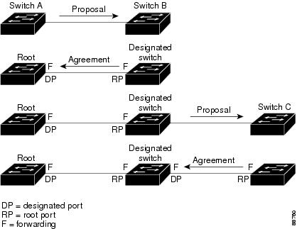
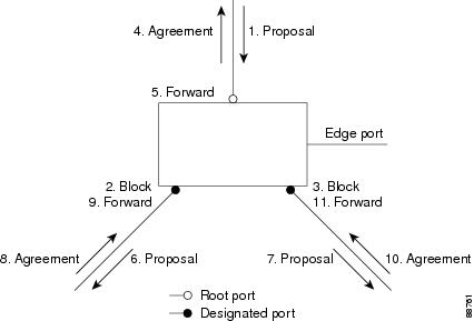
•![]() ポイントツーポイント リンク:ポイントツーポイント リンクを介してポートを別のポートに接続してローカル ポートが指定ポートになる場合、ループのないトポロジを実現するために、提案合意ハンドシェイクを使用して相手側ポートと高速移行をネゴシエーションします。
ポイントツーポイント リンク:ポイントツーポイント リンクを介してポートを別のポートに接続してローカル ポートが指定ポートになる場合、ループのないトポロジを実現するために、提案合意ハンドシェイクを使用して相手側ポートと高速移行をネゴシエーションします。
スイッチ A はポイントツーポイント リンクを介してスイッチ B に接続されており、すべてのポートがブロッキング ステートになります(図 17-8を参照)。スイッチ A のプライオリティがスイッチ Bのプライオリティよりも小さい値であると仮定します。スイッチ A が提案メッセージ(提案フラグが設定されたコンフィギュレーション BPDU)をスイッチ B に送信して、スイッチ A 自身が指定であると提案します。
スイッチ B が提案メッセージを受信すると、提案メッセージを受信したポートを新しいルート ポートとして選択し、すべての非エッジ ポートを強制的にブロッキング ステートにします。さらに、その新しいルート ポート経由で合意メッセージ(合意フラグが設定された BPDU)を送信します。
スイッチ A は、スイッチ B から合意メッセージを受信すると、ただちに自身の指定ポートをフォワーディング ステートにします。スイッチ B はそのすべての非エッジ ポートをブロックしており、さらにスイッチ A と B はポイントツーポイント リンクで接続されているため、ネットワークにループは形成されません。
スイッチ C がスイッチ B に接続された場合も、同様の一連のハンドシェイク メッセージが交換されます。スイッチ C はスイッチ B に接続されたポートをルート ポートとして選択し、両端のポートはすぐにフォワーディング ステートに移行します。このハンドシェイク プロセスの繰り返しによってアクティブ トポロジにスイッチが 1 つ以上追加されます。ネットワークが収束するにつれて、この提案合意ハンドシェイクがルートからスパニング ツリーのリーフに進みます。
スイッチ は、ポートのデュプレックス モードからリンク タイプを判断します。つまり、全二重ポートはポイントツーポイント接続と見なされ、半二重ポートは共有接続と見なされます。 spanning-tree link-type インターフェイス コンフィギュレーション コマンドを使用して、デュプレックス設定で制御されたデフォルト設定を上書きできます。
ポート ロールの同期化
スイッチのポートの 1 つで提案メッセージを受信し、そのポートが新しいルート ポートとして選択されると、RSTP は他のすべてのポートを新しいルート情報と強制的に同期化させます。
他のポートがすべて同期化されると、スイッチはルート ポートで受信した上位のルート情報と同期化されます。次のような場合、スイッチの個別のポートが同期されます。
•![]() エッジ ポート(ネットワークのエッジ上に設定されているポート)の場合
エッジ ポート(ネットワークのエッジ上に設定されているポート)の場合
指定ポートがフォワーディング ステートでエッジ ポートとして設定されていない場合、RSTP によって新しいルート情報と強制的に同期化されると、その指定ポートはブロッキング ステートに移行します。一般に、RSTP がポートをルート情報と強制的に同期させ、ポートが上記のどの条件も満たしていない場合、そのポートのステートはブロッキングに設定されます。
スイッチはすべてのポートが同期されたことを確認すると、そのルート ポートに対応する指定スイッチに合意メッセージを送信します。ポイントツーポイント リンクによって接続されたスイッチがそれぞれのポート ロールについて合意すると、RSTP はポートのステートを即座にフォワーディング ステートに移行させます。図 17-9に、このイベント シーケンスを示します。
ブリッジ プロトコル データ ユニット(BPDU)の形式と処理
BPDU 形式と処理の概要
RSTP BPDU の形式は、プロトコル バージョンが 2 に設定されている点を除き、802.1D BPDU の形式と同じです。新しい 1 バイトのバージョン 1 の Length フィールドは、0 に設定されます。これは、バージョン 1 のプロトコル情報が存在しないことを意味します。 表 17-4 に、RSTP フラグ フィールドを示します。
|
|
|
|---|---|
送信スイッチは、自身をその LAN の指定スイッチとして提案する提案フラグを RSTP の BPDU に設定します。提案メッセージでは、ポート ロールは常に指定ポートに設定されます。
送信スイッチは、前の提案を受け入れる合意フラグを RSTP の BPDU に設定します。合意メッセージ内のポート ロールは、常にルート ポートに設定されます。
RSTP には 個別の Topology Change Notification(TCN; トポロジ変更通知)BPDU はありません。トポロジの変更を示すには、トポロジ変更(TC)フラグを使用します。ただし、802.1D スイッチと相互運用性を保つために、RSTP スイッチは TCN BPDU の処理と生成を行います。
上位 BPDU 情報の処理
上位 BPDU は、現在ポートに格納されているものよりも上位のルート情報(小さいスイッチ ID、低いパス コストなど)を持つ BPDU です。
ポートが上位 BPDU を受信すると、RSTP は再設定を開始します。そのポートが新しいルート ポートとして提案され選択されると、RSTP は他のすべてのポートを強制的に同期化します。
受信した BPDU が提案フラグの設定された RSTP BPDU である場合、スイッチは他のすべてのポートを同期化してから合意メッセージを送信します。BPDU が 802.1D BPDU の場合、スイッチは提案フラグを設定せずにポートの転送遅延タイマーを開始します。新しいルート ポートは、フォワーディング ステートに移行するために 2 倍の転送遅延時間を必要とします。
ポートで上位の情報が受信されたために、そのポートがバックアップ ポートまたは代替ポートになる場合、RSTP はポートをブロッキング ステートに設定し、合意メッセージを送信します。指定ポートは、転送遅延タイマーが満了するまで、提案フラグの設定された BPDU の送信を続けます。タイマーが満了すると、ポートはフォワーディング ステートに移行します。
下位 BPDU 情報の処理
下位 BPDU は、現在ポートに格納されているものよりも下位のルート情報(大きいスイッチ ID、高いパス コストなど)を持つ BPDU です。
トポロジの変更
スパニング ツリー トポロジの変更を処理する際の RSTP と 802.1D との違いは以下のとおりです。
•![]() 検出:802.1D では、 どのような ブロッキング ステートとフォワーディング ステートとの間の移行でもトポロジの変更が発生しますが、RSTP でトポロジの変更が生じるのは、ブロッキング ステートからフォワーディング ステートに移行する場合 だけ です(トポロジの変更と見なされるのは、接続数が増加する場合だけです)。エッジ ポートでステートが変更されても、トポロジの変更は発生しません。RSTP スイッチはトポロジの変更を検出すると、TC 通知を受信するものを除いたすべての非エッジ ポートで学習済みの情報を削除します。
検出:802.1D では、 どのような ブロッキング ステートとフォワーディング ステートとの間の移行でもトポロジの変更が発生しますが、RSTP でトポロジの変更が生じるのは、ブロッキング ステートからフォワーディング ステートに移行する場合 だけ です(トポロジの変更と見なされるのは、接続数が増加する場合だけです)。エッジ ポートでステートが変更されても、トポロジの変更は発生しません。RSTP スイッチはトポロジの変更を検出すると、TC 通知を受信するものを除いたすべての非エッジ ポートで学習済みの情報を削除します。
•![]() 通知:RSTP は、802.1D のように TCN BPDU を使用しません。ただし、802.1D と相互運用性を保つために、RSTP スイッチは TCN BPDU の処理と生成を行います。
通知:RSTP は、802.1D のように TCN BPDU を使用しません。ただし、802.1D と相互運用性を保つために、RSTP スイッチは TCN BPDU の処理と生成を行います。
•![]() 確認:RSTP スイッチは、指定ポートで 802.1D スイッチから TCN メッセージを受信すると、TCA ビットが設定された 802.1D コンフィギュレーション BPDU で応答します。ただし、802.1D スイッチに接続されたルート ポートで TC 時間タイマー(802.1D の TC タイマーと同じ)がアクティブであり、TCA が設定されたコンフィギュレーション BPDU を受信した場合、TC 時間タイマーがリセットされます。
確認:RSTP スイッチは、指定ポートで 802.1D スイッチから TCN メッセージを受信すると、TCA ビットが設定された 802.1D コンフィギュレーション BPDU で応答します。ただし、802.1D スイッチに接続されたルート ポートで TC 時間タイマー(802.1D の TC タイマーと同じ)がアクティブであり、TCA が設定されたコンフィギュレーション BPDU を受信した場合、TC 時間タイマーがリセットされます。
この動作方法は、802.1D スイッチをサポートする場合に限り必要です。RSTP の BPDU には、TCA ビットが設定されません。
•![]() 伝播:RSTP スイッチが指定ポートまたはルート ポート経由で別のスイッチから TC メッセージを受信すると、そのすべての非エッジ ポート、指定ポート、およルート ポート(受信ポートを除く)にトポロジ変更が伝播されます。スイッチは、これらのすべてのポートの TC 時間タイマーを開始し、これらのポート上で学習した情報をフラッシュします。
伝播:RSTP スイッチが指定ポートまたはルート ポート経由で別のスイッチから TC メッセージを受信すると、そのすべての非エッジ ポート、指定ポート、およルート ポート(受信ポートを除く)にトポロジ変更が伝播されます。スイッチは、これらのすべてのポートの TC 時間タイマーを開始し、これらのポート上で学習した情報をフラッシュします。
•![]() プロトコルの移行:802.1D スイッチとの下位互換性を保つために、RSTP は 802.1D コンフィギュレーション BPDU と TCN BPDU をポート単位で選択的に送信します。
プロトコルの移行:802.1D スイッチとの下位互換性を保つために、RSTP は 802.1D コンフィギュレーション BPDU と TCN BPDU をポート単位で選択的に送信します。
ポートが初期化されると、移行遅延タイマーが開始され(RSTP BPDU を送信する最短時間を指定)、RSTP BPDU が送信されます。このタイマーがアクティブの間、スイッチは目的のポートで受信されたすべての BPDU を処理し、プロトコル タイプは無視します。
ポートの移行遅延タイマーの期限が切れたあとに、スイッチが 802.1D BPDU を受信した場合、スイッチは 802.1D スイッチに接続されたと認識し、802.1D BPDU だけの使用を開始します。ただし、RSTP スイッチがポートで 802.1D BPDU を使用している場合に、タイマー満了後に RSTP BPDU を受信すると、スイッチはタイマーを再起動し、そのポートで RSTP BPDU の使用を開始します。
Rapid Per-VLAN Spanning-Tree(Rapid PVST)
Rapid PVST は既存の PVST+ 用の設定を使用します。しかしながら、Rapid PVST は RSTP を使用してより速いコンバージェンスを提供します。独立 VLAN は、独自の RSTP インスタンスを実行します。
ダイナミック エントリは、トポロジ変更を受信すると、ポート単位ですぐに消去されます。
UplinkFast および BackboneFast コンフィギュレーションは Rapid PVST モードでは無視され、両機能は RSTP に含まれます。
MST の概要
•![]() 「MST 領域」
「MST 領域」
•![]() 「境界ポート」
「境界ポート」
•![]() 「IEEE 802.1D-1998 STP との相互運用性」
「IEEE 802.1D-1998 STP との相互運用性」
MST の概要
MST は、複数の VLAN をスパニング ツリー インスタンスにマッピングします。各インスタンスには他のスパニング ツリー インスタンスとは別のスパニング ツリー トポロジがあります。このアーキテクチャにより、データ トラフィック用に複数の転送パスが提供され、ロード バランスが使用可能になり、多くの VLAN をサポートするために必要なスパニング ツリー インスタンスの数が減少します。MST では、1 つのインスタンス(転送パス)で障害が発生しても他のインスタンス(転送パス)には影響しないため、ネットワークのフォールトトレランスが改善されます。
MST の最も一般的な初期配置は、レイヤ 2 スイッチド ネットワークのバックボーンおよびディストリビューション レイヤへの配置です。この配置により、サービスプロバイダー環境で必要な一種の高可用性ネットワークを提供することになります。
MST は、明示的なハンドシェイクを通じてラピッド スパニング ツリー コンバージェンスを提供しています。これにより802.1D 転送遅延を解消して、迅速にルート ブリッジ ポートと指定ポートをフォワーディング ステートに移行させることができます。
MST は、スパニング ツリー動作を改善し、以下の STP バージョンと下位互換性を維持しています。
•![]() 既存のシスコ独自 Multiple Instance STP(MISTP)
既存のシスコ独自 Multiple Instance STP(MISTP)
•![]() 既存の Cisco Per-VLAN Spanning Tree Plus(PVST+)
既存の Cisco Per-VLAN Spanning Tree Plus(PVST+)
•![]() Rapid Per-VLAN Spanning Tree Plus(Rapid PVST+)
Rapid Per-VLAN Spanning Tree Plus(Rapid PVST+)
PVST+ および Rapid PVST+機能の詳細については、 第 17 章「スパニング ツリー プロトコル(STP)およびMultiple Spanning Tree(MST)の設定」 を参照してください。PortFast、UplinkFast、ルートガードなどの他のスパニング ツリー機能の詳細については、 第 18 章「オプションのスパニングツリー プロトコル(STP)機能の設定」 を参照してください。
(注) • IEEE 802.1w は、Rapid SpanningTree Protocol(RSTP)を定義しており、IEEE802.1D に組み込まれました。
•![]() IEEE 802.1s は MST を定義しており、IEEE 802.1Q に組み込まれました。
IEEE 802.1s は MST を定義しており、IEEE 802.1Q に組み込まれました。
MST 領域
MST インスタンスに参加するスイッチに対して、常に同じ MST コンフィギュレーション情報を使用してスイッチを設定する必要があります。同じ MST コンフィギュレーションを持つ相互接続されたスイッチの集合体が MST 領域を構成します(図 17-10を参照)。
MST コンフィギュレーションは、各スイッチが属する MST 領域を制御します。このコンフィギュレーションには、領域名、リビジョン番号、MST VLAN とインスタンスの割り当てマップが含まれています。
1 つの領域に同じ MST コンフィギュレーションを持つ 1 つまたは複数のメンバーを設定でき、各メンバーには RSTP BPDU を処理する能力がなければなりません。ネットワーク内の MST 領域数には制限がありませんが、各領域は最大で 65 のスパニング ツリー インスタンスをサポートできます。インスタンスは、0 ~ 4094 の領域の任意の番号で識別されます。1 つの VLAN を同時に割り当てることのできるスパニング ツリー インスタンスは 1 つだけです。
IST、CIST、およびCST
これらのセクションでは、Internal Spanning Tree(IST; 内部スパニング ツリー)、Common and Internal Spanning-Tree(CIST)、および Common Spanning Tree(CST; 共通スパニング ツリー)について説明します。
IST、CIST、および CST の概要
すべてのスパニング ツリー インスタンスが独立している他のスパニング ツリー プロトコルとは異なり、MST は IST、CIST、CST スパニング ツリーを確立し、維持します。
•![]() IST は 1 つの MST 領域で稼動するスパニング ツリーです。
IST は 1 つの MST 領域で稼動するスパニング ツリーです。
各 MST 領域内では、MST は複数のスパニング ツリー インスタンスを維持しています。インスタンス 0 は領域の特殊インスタンスで、IST と呼ばれています。他のすべての MST インスタンスは 1 ~ 4094 の番号が振られています。
IST は BPDU を送受信する唯一のスパニング ツリー インスタンスです。他のすべてのスパニング ツリー インスタンス情報は、MSTP レコード(M レコード)に含まれていて、MST BPDU 内でカプセル化されています。MST BPDU はすべてのインスタンスの情報を伝送するため、複数のスパニング ツリー インスタンスをサポートするために処理しなければならない BPDU の数は大幅に削減されます。
同じ領域内にあるすべての MST インスタンスは同じプロトコル タイマーを共有していますが、各 MST インスタンスにはルート ブリッジ ID、ルート パス コストなどの独自のトポロジ パラメータがあります。デフォルトでは、すべての VLANは IST に割り当てられています。
MST インスタンスは領域に対してローカルです。たとえば、領域 A と B が相互接続されている場合でも、領域 A の MST インスタンス 1 は 領域 B の MST インスタンス 1 から独立しています。
•![]() CIST は、各 MST 領域にある IST の集合です。
CIST は、各 MST 領域にある IST の集合です。
•![]() CST は MST 領域と単一のスパニング ツリーを相互接続します。
CST は MST 領域と単一のスパニング ツリーを相互接続します。
1 つの領域内で計算されたスパニング ツリーは、スイッチド ドメイン全体を網羅する CST のサブツリーと見なされます。CIST は802.1w、802.1s、802.1D 標準をサポートするスイッチ間で動作するスパニング ツリー アルゴリズムによって形成されます。MST 領域内にある CIST は領域外にある CST と同じです。
詳細については、「MST 領域内のスパニング ツリー動作」および「MST 領域間のスパニング ツリー動作」を参照してください。
MST 領域内のスパニング ツリー動作
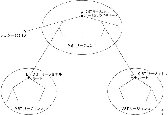
IST は領域内のすべての MST スイッチを接続します。IST が収束する際に、IST のルートが(802.1s 標準の実装前には IST マスター と呼ばれていた)CIST リージョナル ルートとなります(図 17-10を参照)。CIST リージョナル ルートは、ネットワーク内に領域が 1 つしかない場合は CIST ルートでもあります。CIST ルートが MST 領域外にある場合、領域の境界にある MST スイッチの 1 つが CIST リージョナル ルートとして選択されます。
MST スイッチは、初期化時に、自身が CIST と CIST リージョナル ルートであると主張するため、CIST ルートと CIST リージョナル ルートへのパス コストを 0 に設定する BPDU を送信します。スイッチは、さらにすべての MST インスタンスも初期化し、自身がこれらすべてのルートであると主張します。スイッチが現在ポートに格納されているものよりも上位の MST ルート情報(小さいスイッチ ID、低いパス コストなど)を受信すると、CIST リージョナル ルートとしての主張を撤回します。
初期化中に、領域内に独自の CIST リージョナル ルートを持つ多くのサブ領域が形成される場合があります。スイッチは、上位の IST 情報を同じ領域のネイバーから受信すると、古いサブ 領域を脱退して真の CIST リージョナル ルートが含まれる新しいサブ 領域に加入します。これにより、真の CIST リージョナル ルートが含まれるものを除くすべてのサブ 領域が縮小します。
正しく動作するために、MST 領域内のすべてのスイッチは同じ CIST リージョナル ルートを承認する必要があります。したがって、領域内にある任意の 2 つのスイッチは、共通 CIST リージョナル ルートに収束する場合、MST インスタンスに対するポート ロールだけを同期します。
MST 領域間のスパニング ツリー動作
複数の領域または 802.1D スイッチがネットワーク内にある場合、MST が CST を確立して維持します。これには、ネットワーク内のすべての MST 領域とすべての 802.1D STP スイッチが含まれます。MST インスタンスは領域の境界で IST と結合して CST になります。
IST は領域内のすべての MST スイッチを接続し、スイッチド ドメイン全体を網羅する CIST 内のサブツリーとして認識されます。サブツリーのルートは CIST リージョナル ルートです。MST 領域は、隣接する STP スイッチおよび MST 領域からは仮想スイッチとして認識されます。
図 17-10 は、3 つの MST 領域および 802.1D スイッチ(D)があるネットワークを示しています。領域 1 の CIST リージョナル ルート(A)は CIST ルートでもあります。領域 2 の CIST リージョナル ルート(B)および領域 3 の CIST リージョナル ルート(C)は、CIST 内の各サブツリーのルートです。
図 17-10 MST 領域、CIST リージョナル ルート、および CST ルート
CST インスタンスだけが BPDU を送受信し、MST インスタンスがスパニング ツリー情報を BPDU に追加して、隣接スイッチと通信し、最終的なスパニング ツリー トポロジを計算します。このため、BPDU 送信に関連したスパニング ツリー パラメータ(たとえば hello タイム、転送時間、最大エージング タイム、最大ホップ数など)は、CST インスタンスだけで設定されますが、すべての MST インスタンスに影響します。スパニング ツリー トポロジに関連するパラメータ(スイッチ プライオリティ、ポート VLAN コスト、ポート VLAN プライオリティなど)は CST インスタンスと MST インスタンスの両方で設定できます。
MST スイッチは、バージョン 3 BPDU または 802.1D STP BPDU を使用して 802.1D スイッチと通信します。MST スイッチは MST BPDU を使用して MST スイッチと通信します。
IEEE 802.1s 用語
先行標準実装で使用されている MST 命名規則の中には、 内部 および リージョナル パラメータの ID を含めるように変更されたものもあります。これらのパラメータは、ネットワーク全体で使用されている外部パラメータとは違い、MST 領域だけで使用されます。CIST はネットワーク全体にまたがる唯一のスパニング ツリー インスタンスなので、CIST パラメータでは、内部修飾子や領域の修飾子ではなく、外部修飾子が必要です。
•![]() CIST ルートは CIST のルート ブリッジで、ネットワーク全体にまたがる一意のインスタンスです。
CIST ルートは CIST のルート ブリッジで、ネットワーク全体にまたがる一意のインスタンスです。
•![]() CIST 外部ルート パス コストは、CIST ルートのコストです。このコストは、MST 領域内では変化しません。MST 領域は CIST に対して単一のスイッチのように見えることに注意してください。CIST 外部ルート パス コストは、これらの仮想スイッチとどの領域にも属さないスイッチとの間で計算されたルート パス コストです。
CIST 外部ルート パス コストは、CIST ルートのコストです。このコストは、MST 領域内では変化しません。MST 領域は CIST に対して単一のスイッチのように見えることに注意してください。CIST 外部ルート パス コストは、これらの仮想スイッチとどの領域にも属さないスイッチとの間で計算されたルート パス コストです。
•![]() CIST リージョナル ルートは、先行標準実装では IST マスターと呼ばれていました。CIST ルートが領域内にある場合、CIST リージョナル ルートは CIST ルートです。それ以外の場合は、領域内で CIST ルートに最も近いスイッチが CIST リージョナル ルートです。CIST リージョナル ルートは IST のルート ブリッジとして動作します。
CIST リージョナル ルートは、先行標準実装では IST マスターと呼ばれていました。CIST ルートが領域内にある場合、CIST リージョナル ルートは CIST ルートです。それ以外の場合は、領域内で CIST ルートに最も近いスイッチが CIST リージョナル ルートです。CIST リージョナル ルートは IST のルート ブリッジとして動作します。
•![]() CIST 内部ルート パス コストは、領域内の CIST リージョナル ルートのコストです。このコストは、IST(インスタンス 0)だけに関連します。
CIST 内部ルート パス コストは、領域内の CIST リージョナル ルートのコストです。このコストは、IST(インスタンス 0)だけに関連します。
表 17-5 では、IEEE 標準の用語とシスコ先行標準の用語とを比較します。
|
|
|
|
|---|---|---|
ホップ カウント
スパニング ツリー トポロジを計算するためにコンフィギュレーション BPDU の MST はメッセージ有効期間および最大エージング タイムの情報を使用しません。その代わりに、ルートへのパス コストおよび IP Time to Live(TTL)メカニズムに似たホップ カウント メカニズムを使用します。
spanning-tree mst max-hops グローバル コンフィギュレーション コマンドを使用することで、領域内の最大ホップを設定してそれをその領域内にある IST およびすべての MST インスタンスに適用できます。ホップ カウントは、メッセージ有効期間情報と同じ結果(再設定の開始)となります。インスタンスのルート ブリッジは、常にコスト 0 でホップ カウントが最大値に設定されている BPDU(または M レコード)を送信します。スイッチがこの BPDU を受信すると、受信 BPDU の残存ホップ カウントから 1 だけ差し引いた値を残存ホップ カウントとする BPDU を生成し、これを伝播します。ホップ カウントが 0 になると、スイッチは BPDU を廃棄して、ポートに維持された情報を期限切れにします。
BPDU の RSTP 部分に格納されているメッセージ有効期間および最大エージング タイムの情報は、領域全体で同じままです。同じ値が、境界にある領域の指定ポートによって伝播されます。
境界ポート
シスコ先行標準の実装では、境界ポートは MST 領域を次の STP 領域のいずれかに接続します。
•![]() PVST + または Rapid PVST+ を稼動する単一のスパニング ツリー領域
PVST + または Rapid PVST+ を稼動する単一のスパニング ツリー領域
•![]() 異なる MST コンフィギュレーションを持つ別の MST 領域
異なる MST コンフィギュレーションを持つ別の MST 領域
境界ポートは LAN にも接続されています。LAN の指定スイッチは、単一のスパニング ツリー スイッチ、または異なる MST コンフィギュレーションを持つスイッチのいずれかです。
802.1s 標準には境界ポートの定義はありません。802.1Q-2002 標準では、ポートが受信できるメッセージを内部(同一領域内から発信)と外部の 2 種類に分別します。メッセージが外部の場合、CIST だけが受信します。CIST の役割がルートまたは代替ルートの場合、または外部 BPDU がトポロジ変更の場合、MST インスタンスに影響する可能性があります。メッセージが内部の場合、CIST が CIST 部分を受信し、各 MST インスタンスが関連する M レコードを受信します。シスコ先行標準の実装では、外部メッセージを受信するポートを境界ポートとして扱います。そのため、ポートは内部メッセージと外部メッセージの両方を受信できません。
MST 領域には、スイッチと LAN の両方が含まれます。セグメントは、その指定ポートの領域に属します。したがって、セグメントの指定ポートとは異なる領域にあるポートが境界ポートとなります。この定義により、領域の内側にある 2 つのポートが異なる領域に属するポートとセグメントを共有できるので、内部メッセージと外部メッセージの両方をポートで受信できる可能性があります。
シスコ先行標準実装からの主な変更点は、指定ポートが STP 互換モードで動作しない場合は境界ポートとして定義されないことです。
(注) セグメントに 802.1D STP スイッチがある場合、メッセージは常に外部と見なされます。
先行標準からのその他の変更として、RSTP またはレガシー 802.1s スイッチの送信側スイッチ ID が含まれる場所へ、CIST リージョナル ルート ブリッジ ID フィールドが挿入されるという点があります。一貫した送信側スイッチ ID を近接スイッチに送信することにより、領域全体が単一の仮想スイッチとして動作します。この例では、A または B がセグメントで指定されているかどうかにかかわらず、スイッチ C はルートの送信側スイッチ ID が同一である BPDU を受信します。
標準準拠 MST 実装
標準準拠 MST 実装には、標準を満たすために必要な機能と、現在公表されている標準にまだ採用されていない先行標準機能の中で望ましい機能の一部が含まれています。ここでは、標準準拠 MST 実装について説明します。
ポート ロール命名の変更
境界の役割は、最終 MST 標準で削除されましたが、この境界の概念は標準準拠実装では維持されています。ただし、領域の境界にある MST Instance(MSTI; MST インスタンス)ポートは対応する CIST ポートのステートに従わない可能性があります。現在、次の 2 つの状態が存在します。
•![]() 境界ポートが CIST リージョナル ルートのルート ポートである:CIST インスタンス ポートは、提案されて同期が取られている場合、すべての対応 MSTI ポートが同期化された(したがって転送された)あとに限り合意を送り返してフォワーディング ステートに移行することができます。ここで MSTI ポートに、特別に マスター の役割が含まれます。
境界ポートが CIST リージョナル ルートのルート ポートである:CIST インスタンス ポートは、提案されて同期が取られている場合、すべての対応 MSTI ポートが同期化された(したがって転送された)あとに限り合意を送り返してフォワーディング ステートに移行することができます。ここで MSTI ポートに、特別に マスター の役割が含まれます。
•![]() 境界ポートが CIST リージョナル ルートのルート ポートではない:MSTI ポートが CIST ポートのステートと役割に従います。標準で提供される情報は少ないので、BPDU(M レコード)を受信しないときに MSTI ポートを代わりにブロックできる理由を理解するのが難しい場合もあります。この場合、境界の役割がすでに存在していなくても、 show コマンドを入力する際に、出力の type カラムで境界としてポートが識別されます。
境界ポートが CIST リージョナル ルートのルート ポートではない:MSTI ポートが CIST ポートのステートと役割に従います。標準で提供される情報は少ないので、BPDU(M レコード)を受信しないときに MSTI ポートを代わりにブロックできる理由を理解するのが難しい場合もあります。この場合、境界の役割がすでに存在していなくても、 show コマンドを入力する際に、出力の type カラムで境界としてポートが識別されます。
従来の標準と標準準拠スイッチとの間でのスパニング ツリーの相互運用スイッチ
先行標準スイッチの自動検出が失敗することもあるため、インターフェイス コンフィギュレーション コマンドを使用して先行標準ポートを識別できます。標準および先行標準スイッチとの間で領域を形成できませんが、CIST を使用する前に相互運用することはできます。この特定のケースでは、さまざまなインスタンスにおけるロードバランス機能だけが失われます。ポートが先行標準 BPDU を受信する際に、Command Line Interface(CLI; コマンドライン インターフェイス)はポート設定に応じてさまざまなフラグを表示します。先行標準 BPDU 伝送用に設定されていないポートでスイッチが最初に先行標準 BPDU を受信する時に Syslog メッセージも表示されます。
図 17-11 は、先行標準スイッチに接続されている標準準拠スイッチを表しています。A が標準準拠スイッチで B が先行標準スイッチで、いずれも同じ領域に設定されているとします。A は CIST のルート ブリッジで、B にはセグメント X にルート ポート(BX)、およびセグメント Y に代替ポート(BY)があります。セグメント Y がフラップして、BY のポートが単一の先行標準 BPDU を送信する前に代替ポートとなる場合、AY は先行標準スイッチが Y に接続されていることを検出できず、標準 BPSU を送信し続けます。ポート BY は境界に固定され、A と B との間のロード バランスは実行できません。同じ問題はセグメント X にも存在しますが、B はトポロジ変更を送信する場合があります。

(注) 標準 MST 実装と先行標準 MST 実装との間では、相互運用を最小限にすることを推奨します。
単一方向リンク障害の検出
この機能は、IEEE MST 標準にはありませんが、標準準拠実装には含まれています。ブリッジング ループが発生する可能性のある単一方向リンク障害を検出するために、ソフトウェアが受信した BPDU のポート ロールとステートの一貫性をチェックします。
指定ポートが矛盾を検出すると役割は維持されますが、状態は廃棄ステートに戻ります。これは、接続に矛盾が生じた場合、ブリッジング ループを開始するよりも接続を中断する方が好ましいためです。
図 17-12 は、一般的にブリッジング ループを作成する単一方向リンク障害を示します。スイッチ A はルート ブリッジで、その BPDU はスイッチ B へのリンクで損失されます。RSTP および MST BPDU には、送信ポートの役割とステートが含まれます。この情報を使用して、スイッチ A は、スイッチ B が A の送信した上位 BPDU に反応せず、スイッチ B が指定スイッチでルート ブリッジではないことを検出できます。この結果、スイッチ A は B のポートをブロックする(またはブロックし続ける)ため、ブリッジング ループが回避されます。

IEEE 802.1D-1998 STP との相互運用性
MST を実行しているスイッチは、802.1D スイッチと相互運用できるようにする内蔵プロトコル移行機能をサポートします。このスイッチが 802.1D コンフィギュレーション BPDU(プロトコルバージョンが 0 に設定されている BPDU)を受信すると、そのポートの 802.1D BPDU だけを送信します。MST スイッチは、802.1D BPDU、異なる領域と関連付けられている MST BPDU(バージョン 3)、または RSTP BPDU(バージョン 2)を受信するときに、ポートが領域の境界にあることも検出できます。
ただし、スイッチが 802.1D BPDU を受信しなくなっても、自動的に MST モードに戻ることはありません。これは、802.1D スイッチが指定スイッチでない場合、802.1D スイッチがリンクから削除されているかどうかを検出できないためです。さらにスイッチは、このスイッチに接続されているスイッチがその領域に加入した場合、引き続きポートに境界の役割を割り当てる可能性もあります。プロトコル移行プロセスを再起動する(近接スイッチと強制的に再ネゴシエーションする)には、 clear spanning-tree detected-protocols 特権 EXEC コマンドを使用します。
リンク上のすべての 802.1D スイッチが RSTP スイッチの場合、RSTP BPDU のように MST BPDU を処理できます。したがって、MST スイッチがバージョン 0 コンフィギュレーションと Topology Change Notification(TCN)BPDU、または境界ポート上のバージョン 3 MST BPDU のいずれかを送信します。境界ポートは LAN にも接続されています。LAN の指定スイッチは、単一のスパニング ツリー スイッチ、または異なる MST コンフィギュレーションを持つスイッチのいずれかです。
STP の設定
ここでは、VLAN 上での STP の設定手順について説明します。
(注) この章で説明する STP コマンドは任意の LAN ポートに設定できますが、これらのコマンドが有効なのは、switchport キーワードを使用して設定した LAN ポートに限られます。

STP のデフォルト設定
表 17-6 に、STP のデフォルト設定を示します。
STP のイネーブル化
(注) STP は、VLAN 1 および新たに作成されるすべての VLAN で、デフォルトでイネーブルに設定されています。
STP は、VLAN 単位でイネーブルにすることができます。Catalyst 6500 シリーズ スイッチは VLAN ごとに個別の STP インスタンスを維持します(STP をディセーブルに設定した VLAN を除きます)。
VLAN 単位で STP をイネーブルにするには、次の作業を行います。
|
|
|
|
|---|---|---|
VLAN 単位で STP をイネーブルにします。 vlan_ID の値は 1 ~ 4094 です(予約済み VLAN は除く。表 17-6を参照)。 |
||
次に、VLAN200 で STP をイネーブルにする例を示します。
(注) STP はデフォルトでイネーブルに設定されているので、show running コマンドを入力して設定の結果を表示しても、STP をイネーブルにするために入力したコマンドは表示されません。
(注) VLAN 200 スパニング ツリーを作成するには、VLAN 200 にアクティブなインターフェイスが少なくとも 1 つ必要です。この例では、VLAN 200 内の 2 つのインターフェイスがアクティブです。
拡張システム ID のイネーブル化
Catalyst 6500 シリーズ スイッチ上では、拡張システム ID は永続的にイネーブルです。次に、設定を確認する例を示します。
ルート ブリッジの設定
Catalyst 6500 シリーズ スイッチは、アクティブな VLAN ごとに STP のインスタンスを個別に維持します。各インスタンスには、ブリッジ プライオリティおよびブリッジの MAC アドレスで構成されるブリッジ ID が対応付けられます。VLAN ごとに、最小のブリッジ ID を持つネットワーク装置が、その VLAN のルート ブリッジになります。
VLAN インスタンスがルート ブリッジになるように設定するには、 spanning-tree vlan vlan_ID root コマンドを入力して、ブリッジ プライオリティをデフォルト値(32768)から非常に小さな値へと変更します。
spanning-tree vlan vlan_ID root コマンドを入力すると、スイッチは各 VLAN の現在のルート ブリッジのブリッジ プライオリティを確認します。拡張システム ID をイネーブルにすると、24576 という値でスイッチが指定された VLAN のルートになる場合、その VLAN のブリッジ プライオリティはスイッチによって 24576 に設定されます。
拡張システム ID がイネーブルで、指定された VLAN のルート ブリッジのブリッジ プライオリティが 24576 より小さい場合、スイッチはその VLAN のブリッジ プライオリティを最小のブリッジ プライオリティより 4096 小さい値に設定します (4096 は 4 ビット ブリッジ プライオリティの最下位ビットの値です。表 17-1を参照)。
(注) ルート ブリッジになるために必要な値が 1 より小さい場合は、spanning-tree vlan vlan_ID root コマンドは機能しません。
拡張システム ID がイネーブルで、たとえば VLAN 20 のすべてのネットワーク装置にデフォルト プライオリティ 32768 が設定されている場合に、スイッチ上で spanning-tree vlan 20 root primary コマンドを使用すると、ブリッジ プライオリティが 24576 に設定され、そのスイッチが VLAN 20 のルート ブリッジになります。
レイヤ 2 ネットワークの直径(つまり、レイヤ 2 ネットワーク上の任意の 2 つのエンド ステーション間における最大ブリッジ ホップ数)を指定するには、 diameter キーワードを指定します。ネットワーク直径を指定すると、Catalyst 6500 シリーズ スイッチはその直径を持つネットワークに最適な hello タイム、転送遅延時間、および最大エージング タイムを自動的に選びます。その結果、STP のコンバージェンスに要する時間が大幅に短縮されます。 hello キーワードを使用して、自動的に計算される hello タイムを上書きすることができます。
(注) STP トポロジを安定した状態に保つには、Catalyst 6500 シリーズ スイッチをルート ブリッジとして設定したあと、hello タイム、転送遅延時間、および最大エージング タイムを手動で設定しないでください。
Catalyst 6500 シリーズ スイッチをルート ブリッジとして設定するには、次の作業を行います。
|
|
|
|
|---|---|---|
Router(config)# spanning-tree vlan vlan_ID root primary [ diameter hops [ hello-time seconds ]] |
Catalyst 6500 シリーズ スイッチをルート ブリッジとして設定します。 vlan_ID の値は 1 ~ 4094 です(予約済み VLAN は除く。表 17-6を参照)。 |
|
次に、Catalyst 6500 シリーズ スイッチを VLAN 10 のルート ブリッジとして設定し、ネットワーク直径を 4 に設定する例を示します。
セカンダリ ルート ブリッジの設定
Catalyst 6500 シリーズ スイッチをセカンダリ ルートとして設定すると、STP ブリッジ プライオリティはデフォルト値(32768)から変更されます。その結果、プライマリ ルート ブリッジに障害が発生した場合に(ネットワーク上の他のネットワーク装置がデフォルトのブリッジ プライオリティ 32768 を使用していると仮定して)、このスイッチが指定された VLAN のルート ブリッジになる可能性が高くなります。
拡張システム ID がイネーブルの場合、STP によってブリッジ プライオリティが 28672 に設定されます。
このコマンドを複数の スイッチに対して実行すると、複数のバックアップ ルート ブリッジを設定できます。プライマリ ルート ブリッジを設定するときに使用したものと同じネットワーク直径および hello タイムを使用してください。
Catalyst 6500 シリーズ スイッチをセカンダリ ルート ブリッジとして設定するには、次の作業を行います。
|
|
|
|
|---|---|---|
Router(config)# [ no ] spanning-tree vlan vlan_ID root secondary [ diameter hops [ hello-time seconds ]] |
Catalyst 6500 シリーズ スイッチをセカンダリ ルート ブリッジとして設定します。 vlan_ID の値は 1 ~ 4094 です(予約済み VLAN は除く。表 12-1を参照)。 |
|
次に、Catalyst 6500 シリーズ スイッチを VLAN 10 のセカンダリ ルート ブリッジとして設定し、ネットワーク直径を 4 に設定する例を示します。
STP ポート プライオリティの設定
ループが発生すると、STP はポート プライオリティを考慮して、フォワーディング ステートにする LAN ポートを選択します。STP に最初に選択させる LAN ポートには高いプライオリティ値を、最後に選択させる LAN ポートには低いプライオリティ値を割り当てることができます。すべての LAN ポートが同じプライオリティ値を使用している場合には、STP は LAN ポート番号が最も小さい LAN ポートをフォワーディング ステートにして、残りの LAN ポートをブロックします。指定できるプライオリティの範囲は 0 ~ 240 であり(デフォルトは 128)、16 単位で設定できます。
Cisco IOS は LAN ポートがアクセス ポートとして設定されている場合にはポート プライオリティ値を使用し、LAN ポートがトランク ポートとして設定されている場合には VLAN ポート プライオリティ値を使用します。
レイヤ 2 LAN インターフェイスの STP ポート プライオリティを設定するには、次の作業を行います。
|
|
|
|
|---|---|---|
Router(config)# interface {{ gigabitethernet 1 /port } | { port-channel port_channel_number }} |
||
Router(config-if)# spanning-tree port-priority port_priority |
LAN インターフェイスのポート プライオリティを設定します。指定できる port_priority 値の範囲は 4 単位で、1 ~ 252 です。 |
|
Router(config-if)# spanning-tree vlan vlan_ID port-priority port_priority |
LAN インターフェイスの VLAN ポート プライオリティを設定します。指定できる port_priority 値の範囲は 4 単位で、1 ~ 252 です。 vlan_ID の値は 1 ~ 4094 です(予約済み VLAN は除く。表 12-1を参照)。 |
|
Router(config-if)# [ no ] spanning-tree vlan vlan_ID port-priority |
||
Router# show spanning-tree interface { gigabitethernet 1 /port } | { port-channel port_channel_number } |
次に、ポート GigabitEthernet 1/4 の STP ポート プライオリティを設定する例を示します。
次に、ポート GigabitEthernet 1/4 の設定を確認する例を示します。
ポート GigabitEthernet 1/4 はトランクです。この例のように、複数の VLAN が設定され、アクティブになっています。ポート プライオリティ設定は、この VLAN インターフェイス上のすべての VLAN に適用されます。
(注) show spanning-tree interface コマンドで情報が表示されるのは、ポートが接続され動作している場合に限られます。これらの条件が満たされていない場合は、show running-config interface コマンドを使用して設定を確認してください。
次に、ポート GigabitEthernet 1/4 の VLAN ポート プライオリティを設定する例を示します。
この例で入力した設定は VLAN 200 にだけ適用されます。200 以外のすべての VLAN のポート プライオリティは 160 のままです。
VLAN 200 のスパニング ツリー情報を表示するには、次のコマンドを使用します。
STP ポート コストの設定
STP ポート パス コストのデフォルト値は、LAN インターフェイスのメディア速度から決定されます。ループが発生すると、STP はポート コストを考慮して、フォワーディング ステートにする LAN インターフェイスを選択します。STP で最初に選択させる LAN インターフェイスには低いコスト値を、最後に選択させる LAN インターフェイスには高いコスト値を割り当てることができます。すべての LAN インターフェイスが同じコスト値を使用している場合には、STP は LAN インターフェイス番号が最も小さい LAN インターフェイスをフォワーディング ステートにして、残りの LAN インターフェイスをブロックします。指定できるコストの範囲は、0 ~ 200000000 です(デフォルトは、メディアによって異なります)。
STP は LAN インターフェイスがアクセス ポートとして設定されている場合にはポート コスト値を使用し、LAN インターフェイスがトランク ポートとして設定されている場合には VLAN ポート コスト値を使用します。
レイヤ 2 LAN インターフェイスの STP ポート コストを設定するには、次の作業を行います。
|
|
|
|
|---|---|---|
Router(config)# interface {{ gigabitethernet 1 /port } | { port-channel port_channel_number }} |
||
LAN インターフェイスのポート コストを設定します。 port_cost 値は、1 ~ 200000000 の範囲で指定します。 |
||
Router(config-if)# spanning-tree vlan vlan_ID cost port_cost |
LAN インターフェイスの VLAN ポート コストを設定します。 port_cost 値は、1 ~ 200000000 の範囲で指定します。 vlan_ID の値は 1 ~ 4094 です(予約済み VLAN は除く。表 12-1を参照)。 |
|
Router# show spanning-tree interface { gigabitethernet 1 /port } | { port-channel port_channel_number } |
次に、ポート GigabitEthernet 1/4 の STP ポート コストを変更する例を示します。
次に、VLAN 200 の各ポート VLAN コストにポート プライオリティを設定する例を示します。
(注) 他の VLAN(VLAN 1 など)では次に示す出力は、この設定の影響を受けていません。
(注) show spanning-tree コマンドで情報が表示されるのは、ポートがリンクアップ動作可能ステートで、かつ DTP 用に正しく設定されている場合に限られます。これらの条件が満たされていない場合は、show running-config コマンドを入力して設定を確認してください。
VLAN のブリッジ プライオリティの設定
(注) このコマンドは、慎重に使用してください。ブリッジ プライオリティを変更するには、ほとんどの状況で spanning-tree vlan vlan_ID root primary コマンドおよび spanning-tree vlan vlan_ID root secondary コマンドを使用することを推奨します。
VLAN の STP ブリッジ プライオリティを設定するには、次の作業を行います。
|
|
|
|
|---|---|---|
Router(config)# spanning-tree vlan vlan_ID priority { 0 | 4096 | 8192 | 12288 | 16384 | 20480 | 24576 | 28672 | 32768 | 36864 | 40960 | 45056 | 49152 | 53248 | 57344 | 61440 } |
拡張システム ID がイネーブルの場合に、VLAN のブリッジ プライオリティを設定します。 vlan_ID の値は 1 ~ 4094 です(予約済み VLAN は除く。表 12-1を参照)。 |
|
次に、拡張システム ID がディセーブルの場合に、VLAN 200 のブリッジ プライオリティを 33792 に設定する例を示します。
hello タイムの設定
(注) このコマンドは、慎重に使用してください。hello タイムを変更するには、ほとんどの状況で spanning-tree vlan vlan_ID root primary コマンドおよび spanning-tree vlan vlan_ID root secondary コマンドを使用することを推奨します。
VLAN の STP hello タイムを設定するには、次の作業を行います。
|
|
|
|
|---|---|---|
Router(config)# spanning-tree vlan vlan_ID hello-time hello_time |
VLAN の hello タイムを設定します。 hello_time 値は、1 ~ 10 秒の範囲で指定します。 vlan_ID の値は 1 ~ 4094 です(予約済み VLAN は除く。表 12-1を参照)。 |
|
次に、VLAN 200 の hello タイムを 7 秒に設定する例を示します。
VLAN の転送遅延時間の設定
VLAN の STP 転送遅延時間を設定するには、次の作業を行います。
|
|
|
|
|---|---|---|
Router(config)# spanning-tree vlan vlan_ID forward-time forward_time |
VLAN の転送時間を設定します。 forward_time 値は、4 ~ 30 秒の範囲で指定します。 vlan_ID の値は 1 ~ 4094 です(予約済み VLAN は除く。表 12-1を参照)。 |
|
次に、VLAN 200 の転送遅延時間を 21 秒に設定する例を示します。
VLAN の最大エージング タイムの設定
VLAN の STP 最大エージング タイムを設定するには、次の作業を行います。
|
|
|
|
|---|---|---|
VLAN の最大エージング タイムを設定します。 max_age 値は、6 ~ 40 秒の範囲で指定します。 vlan_ID の値は 1 ~ 4094 です(予約済み VLAN は除く。表 12-1を参照)。 |
||
次に、VLAN 200 の最大エージング タイムを 36 秒に設定する例を示します。
Rapid PVST のイネーブル化
Rapid PVST は、既存の PVST+ フレームワークを設定や他の機能との相互通信に利用します。また、MSTP 内の PVST+ 拡張機能も一部サポートします。
スイッチの Rapid PVST モードをイネーブルにするには、特権モードで spanning-tree mode rapid-pvst コマンドを入力します。Rapid PVST モードでスイッチを設定するには、「STP の設定」を参照してください。
リンク タイプの指定
高速接続は、ポイントツーポイント リンク上だけに確立されます。スパニング ツリーはポイントツーポイント リンクを、スパニング ツリー アルゴリズムを実行する 2 つのスイッチだけを接続するセグメントと見なします。スイッチは、すべての全二重リンクはポイントツーポイント リンクで、半二重リンクは共有リンクであると見なすので、明示的にリンク タイプの設定を避けることができます。特定のリンク タイプを設定するには、 spanning-tree linktype コマンドを入力します。
プロトコル移行の再起動
MSTP と RSTP の両方を実行するスイッチは、スイッチをレガシー 802.1D スイッチと相互運用できるようにする内蔵プロトコル移行プロセスをサポートします。このスイッチは、レガシー 802.1D コンフィギュレーション BPDU(プロトコルバージョンが 0 に設定されている BPDU)を受信すると、そのポートの 802.1D BPDU だけを送信します。MSTP スイッチは、レガシー BPDU、異なる領域と関連する MST BPDU(バージョン 3)、または RST BPDU(バージョン 2)を受信するときに、ポートが領域の境界にあることも検出できます。
ただし、レガシー スイッチが指定スイッチでない場合、レガシー スイッチがリンクから削除されているかどうか判断できないので、スイッチはこれ以上 802.1D BPDU を受け取らない場合でも、自動的に MSTP モードに戻りません。スイッチは、接続されている スイッチがその領域に加入している場合、ポートに境界の役割を割り当て続ける可能性もあります。
スイッチ全体で、プロトコル移行プロセスを再開するには(近接スイッチと強制的に再ネゴシエーションする)、 clear spanning-tree detected-protocols 特権 EXEC コマンドを使用できます。特定のインターフェイスでプロトコル移行プロセスを再開するには、 clear spanning-tree detected-protocols interface interface-id 特権 EXEC コマンドを入力します。
MST の設定
•![]() 「MST 領域設定の指定と MST のイネーブル化」(必須)
「MST 領域設定の指定と MST のイネーブル化」(必須)
•![]() 「ルート ブリッジの設定」(任意)
「ルート ブリッジの設定」(任意)
•![]() 「セカンダリ ルート ブリッジの設定」(任意)
「セカンダリ ルート ブリッジの設定」(任意)
•![]() 「STP ポート プライオリティの設定」(任意)
「STP ポート プライオリティの設定」(任意)
•![]() 「パス コストの設定」(任意)
「パス コストの設定」(任意)
•![]() 「スイッチ プライオリティの設定」(任意)
「スイッチ プライオリティの設定」(任意)
•![]() 「hello タイムの設定」(任意)
「hello タイムの設定」(任意)
•![]() 「伝送ホールド カウントの設定」(任意)
「伝送ホールド カウントの設定」(任意)
•![]() 「最大エージング タイムの設定」(任意)
「最大エージング タイムの設定」(任意)
•![]() 「最大ホップ カウントの設定」(任意)
「最大ホップ カウントの設定」(任意)
•![]() 「リンク タイプの指定による高速移行」(任意)
「リンク タイプの指定による高速移行」(任意)
•![]() 「ネイバー タイプの指定」(任意)
「ネイバー タイプの指定」(任意)
•![]() 「プロトコル移行プロセスの再起動」(任意)
「プロトコル移行プロセスの再起動」(任意)
デフォルトの MST 設定
表 17-7 に、デフォルトの MST 設定を示します。
|
|
|
|---|---|
MST 設定時の注意事項および制約事項
MST を設定する際に、以下の注意事項と制約事項に従ってください。
•![]() 802.1s MST 標準により、最大 65 個の MST インスタンスを使用可能です。MST インスタンスにマッピングできる VLAN の数に制限はありません。
802.1s MST 標準により、最大 65 個の MST インスタンスを使用可能です。MST インスタンスにマッピングできる VLAN の数に制限はありません。
•![]() PVST+、Rapid PVST+、および MST はサポートされていますが、1 度にアクティブにすることのできるバージョンは 1 つだけです。
PVST+、Rapid PVST+、および MST はサポートされていますが、1 度にアクティブにすることのできるバージョンは 1 つだけです。
•![]() VTP は、MST コンフィギュレーションを伝播しません。CLI または SNMP を使用して、MST 領域内にある各スイッチ上で、MST コンフィギュレーション(領域名、リビジョン番号、VLAN/インスタンス間のマッピング)を手動で設定する必要があります。
VTP は、MST コンフィギュレーションを伝播しません。CLI または SNMP を使用して、MST 領域内にある各スイッチ上で、MST コンフィギュレーション(領域名、リビジョン番号、VLAN/インスタンス間のマッピング)を手動で設定する必要があります。
•![]() ネットワーク内の冗長パス全体でロードバランスを機能させるためには、すべての VLAN/インスタンス間マッピングの割り当てを一致させなければなりません。一致しない場合、すべてのトラフィックが単一リンクに流れます。
ネットワーク内の冗長パス全体でロードバランスを機能させるためには、すべての VLAN/インスタンス間マッピングの割り当てを一致させなければなりません。一致しない場合、すべてのトラフィックが単一リンクに流れます。
•![]() PVST+ および MST クラウド、または Rapid-PVST と MST クラウドとの間でロード バランシングを実現するには、すべての MST 境界ポートがフォワーディング ステートでなければなりません。そのためには、MST クラウドの CIST リージョナル ルートが CST のルートでなければなりません。MST クラウドが複数の MST 領域で構成されている場合、MST 領域の 1 つに CST ルートが含まれていなければならず、その他のすべての MST 領域には MST クラウド内に含まれるルートへのパスが、PVST+ または Rapid-PVST+ クラウドよりも良好なものでなければなりません。
PVST+ および MST クラウド、または Rapid-PVST と MST クラウドとの間でロード バランシングを実現するには、すべての MST 境界ポートがフォワーディング ステートでなければなりません。そのためには、MST クラウドの CIST リージョナル ルートが CST のルートでなければなりません。MST クラウドが複数の MST 領域で構成されている場合、MST 領域の 1 つに CST ルートが含まれていなければならず、その他のすべての MST 領域には MST クラウド内に含まれるルートへのパスが、PVST+ または Rapid-PVST+ クラウドよりも良好なものでなければなりません。
•![]() ネットワークを多数の領域に分割することは推奨しません。ただし、そのような状況が避けられないような場合には、スイッチド LAN を非レイヤ 2 装置と相互接続された小規模な LAN に分割することを推奨します。
ネットワークを多数の領域に分割することは推奨しません。ただし、そのような状況が避けられないような場合には、スイッチド LAN を非レイヤ 2 装置と相互接続された小規模な LAN に分割することを推奨します。
•![]() 既存の MST インスタンスに対して VLAN の追加または削除を行うと、その MST インスタンスに関するスパニング ツリーの再計算が開始され、その MST インスタンスに関するすべての VLAN のトラフィックが中断されます。
既存の MST インスタンスに対して VLAN の追加または削除を行うと、その MST インスタンスに関するスパニング ツリーの再計算が開始され、その MST インスタンスに関するすべての VLAN のトラフィックが中断されます。
MST 領域設定の指定と MST のイネーブル化
複数の スイッチ を同じ MST 領域に設定するには、同じ VLAN/インスタンス間マッピング、同じコンフィギュレーション リビジョン番号、および同じ MST 名を設定する必要があります。
1 つの領域には、同じ MST コンフィギュレーションを持つ 1 つまたは複数のメンバーを設定でき、各メンバーには RSTP BPDUを処理する能力がなければなりません。ネットワーク内の MST 領域数には制限がありませんが、各領域は最大で 65 のスパニング ツリー インスタンスをサポートできます。1 つの VLAN を同時に割り当てることのできるスパニング ツリー インスタンスは 1 つだけです。
MST 領域の設定を指定して MST をイネーブルにするには、次の作業を行います。
•![]() デフォルトの MST 領域設定に戻るには、 no spanning-tree mst configuration グローバル コンフィギュレーション コマンドを使用します。
デフォルトの MST 領域設定に戻るには、 no spanning-tree mst configuration グローバル コンフィギュレーション コマンドを使用します。
•![]() デフォルトの VLAN/インスタンス間マッピングに戻るには、 no instance instance_id [ vlan vlan_range ] MST コンフィギュレーション コマンド を使用します。
デフォルトの VLAN/インスタンス間マッピングに戻るには、 no instance instance_id [ vlan vlan_range ] MST コンフィギュレーション コマンド を使用します。
•![]() デフォルトの名前に戻るには、 no name MSTコンフィギュレーション コマンド を使用します。
デフォルトの名前に戻るには、 no name MSTコンフィギュレーション コマンド を使用します。
•![]() デフォルトのリビジョン番号に戻るには、 no revision MST コンフィギュレーション コマンド を使用します。
デフォルトのリビジョン番号に戻るには、 no revision MST コンフィギュレーション コマンド を使用します。
•![]() PVST+ を再度イネーブルにするには、 no spanning-tree mode または spanning-tree mode pvst グローバル コンフィギュレーション コマンドを入力します。
PVST+ を再度イネーブルにするには、 no spanning-tree mode または spanning-tree mode pvst グローバル コンフィギュレーション コマンドを入力します。
次に、MST コンフィギュレーション モードを開始して、VLAN10 ~ 20 を MST インスタンス 1 にマッピングし、その領域の名前を region1 に設定し、コンフィギュレーション リビジョンを 1 に設定し、入力した設定を表示し、変更を適用して、グローバル コンフィギュレーション モードに戻る例を示します。
ルート ブリッジの設定
スイッチは、マッピングされた VLAN グループのスパニング ツリー インスタンスを維持します。各インスタンスには、スイッチ プライオリティおよびスイッチの MAC アドレスで構成されるスイッチ ID が対応付けられます。VLAN のグループに対して、最小のスイッチ ID を持つスイッチがルート ブリッジとなります。
スイッチがルート ブリッジになるように設定するには、スイッチが指定したスパニング ツリー インスタンスのルート ブリッジとなるように、 spanning-tree mst instance_id root グローバル コンフィギュレーション コマンドを使用して、スイッチ プライオリティをデフォルト値(32768)から非常に小さな値へと変更します。このコマンドを入力する際に、スイッチがルート ブリッジのスイッチ プライオリティを確認します。拡張システム ID をサポートしているため、24576 という値でスイッチが指定したスパニング ツリー インスタンスのルート ブリッジとなる場合、そのスイッチは指定したインスタンスに対する自身のプライオリティを 24576 に設定します。
インスタンスに指定されているルート ブリッジのスイッチ プライオリティが 24576 を下回る場合、スイッチは自身のプライオリティを最も小さなスイッチ プライオリティを下回る 4096 に設定します (4096 は 4 ビット スイッチ プライオリティの最下位ビットの値です。表 17-1を参照)。
ネットワークを構成するスイッチに拡張システム ID をサポートするものとサポートしないものがある場合、拡張システム ID をサポートするスイッチがルート ブリッジになることはありません。拡張システム ID は、VLAN 番号が古いソフトウェアを実行している接続スイッチのプライオリティよりも大きくなるように、スイッチ プライオリティ値を増やします。
各スパニング ツリー インスタンスのルート ブリッジは、バックボーン スイッチまたはディストリビューション スイッチでなければなりません。アクセス スイッチをスパニング ツリーのプライマリ ルート ブリッジとして設定しないでください。
レイヤ 2 ネットワークの直径(つまり、レイヤ 2 ネットワーク上の任意の 2 つのエンド ステーション間における最大ブリッジ ホップ数)を指定するには、MST インスタンス 0 だけで利用可能な diameter キーワードを指定します。ネットワーク直径を指定すると、スイッチはその直径を持つネットワークに最適な hello タイム、転送遅延時間、および最大エージング タイムを自動的に選びます。その結果、コンバージェンスに要する時間が大幅に短縮されます。 hello キーワードを使用して、自動的に計算される hello タイムを上書きすることができます。
(注) ルート ブリッジとして設定されているスイッチを使用する場合、spanning-tree mst hello-time、spanning-tree mst forward-time、および spanning-tree mst max-age を使用して、hello タイム、転送遅延時間、および最大エージング タイムを手動で設定しないでください。
スイッチをルート ブリッジとして設定するには、次の作業を行います。
デフォルトのスイッチ設定に戻るには、 no spanning-tree mst instance_id root グローバル コンフィギュレーション コマンドを使用します。
セカンダリ ルート ブリッジの設定
拡張システム ID をサポートするスイッチをセカンダリ ルートとして設定すると、スイッチ プライオリティはデフォルト値(32768)から 28672 に変更されます。その結果、プライマリ ルート ブリッジに障害が発生した場合に、このスイッチが指定されたインスタンスのルート ブリッジになる可能性が高くなります。この場合、ネットワーク上の他のスイッチがデフォルトのスイッチ プライオリティ 32768 を使用していて、ルート ブリッジになる可能性がないと仮定しています。
このコマンドを複数のスイッチに対して実行すると、複数のバックアップ ルート ブリッジを設定できます。プライマリ ルート ブリッジ を設定する際に使用するのと同じネットワーク直径と hello-time 値を spanning-tree mst instance_id root primary グローバル コンフィギュレーション コマンド で使用してください。
スイッチをセカンダリ ルート ブリッジとして設定するには、次の作業を行います。
|
|
|
|
|---|---|---|
Router(config)# spanning-tree mst instance_id root secondary [ diameter net_diameter [ hello-time seconds ]] |
(任意)スイッチをセカンダリ ルート ブリッジとして設定します。 • • • プライマリ ルート ブリッジを設定するときに使用したものと同じネットワーク直径および hello タイムを使用してください。「ルート ブリッジの設定」を参照してください。 |
|
デフォルトのスイッチ設定に戻るには、 no spanning-tree mst instance_id root グローバル コンフィギュレーション コマンドを使用します。
ポート プライオリティの設定
ループが発生すると、MST はポート プライオリティを使用して、フォワーディング ステートに置くインターフェイスを選択します。MST に最初に選択させるインターフェイスには高いプライオリティ値(小さな数値)を、最後に選択させるインターフェイスには低いプライオリティ値(大きな数値)を割り当てることができます。すべてのインターフェイスが同じプライオリティ値を使用している場合には、MST はインターフェイス番号が最も小さいインターフェイスをフォワーディング ステートにして、残りのインターフェイスをブロックします。
インターフェイスの MST ポート プライオリティを設定するには、次の作業を実行します。
(注) show spanning-tree mst interface interface_id 特権 EXEC コマンドで情報が表示されるのは、ポートがリンクアップ動作可能ステートの場合だけです。それ以外は、show running-config interface 特権 EXEC コマンドを使用して設定を確認します。
インターフェイスをデフォルトの設定に戻すには、 no spanning-tree mst instance_id port-priority グローバル コンフィギュレーション コマンドを使用します。
パス コストの設定
MSTパス コストのデフォルト値は、インターフェイスのメディア速度から抽出されます。ループが発生すると、MST はコストを使用して、フォワーディング ステートに置くインターフェイスを選択します。最初に選択させるインターフェイスには低いコスト値を、最後に選択させるインターフェイスには高いコスト値を割り当てることができます。すべてのインターフェイスが同じコスト値を使用している場合には、MST はインターフェイス番号が最も小さいインターフェイスをフォワーディング ステートにして、残りのインターフェイスをブロックします。
インターフェイスの MST コストを設定するには、次の作業を実行します。
(注) show spanning-tree mst interface interface_id 特権 EXEC コマンドは、リンクアップ動作可能ステートのポートの情報だけを表示します。それ以外は、show running-config 特権 EXEC コマンドを使用して設定を確認します。
インターフェイスをデフォルトの設定に戻すには、 no spanning-tree mst instance_id cost インターフェイス コンフィギュレーション コマンドを使用します。
スイッチ プライオリティの設定
スイッチがルート ブリッジとして選択される可能性が高くなるように、スイッチ プライオリティを設定できます。
(注) このコマンドを使用する場合には注意が必要です。スイッチ プライオリティを変更する場合、ほとんどの状況で spanning-tree mst instance_id root primary および spanning-tree mst instance_id root secondary コマンドを使用することを推奨します。
スイッチ プライオリティを設定するには、次の作業を行います。
スイッチをデフォルト設定に戻すには、 no spanning-tree mst instance_id priority グローバル コンフィギュレーション コマンドを使用します。
hello タイムの設定
hello タイムを変更することでルート ブリッジによって作成される設定メッセージの間隔を設定できます。
(注) このコマンドを使用する場合には注意が必要です。hello 時間を変更する場合、ほとんどの状況で spanning-tree mst instance_id root primary および spanning-tree mst instance_id root secondary コマンドを使用することを推奨します。
すべての MST インスタンスに対して hello タイムを設定するには、次の作業を行います。
|
|
|
|
|---|---|---|
(任意)すべての MST インスタンスに対して hello タイムを設定します。hello タイムは、ルート ブリッジによって作成される設定メッセージの間隔です。これらのメッセージは、スイッチが動作していることを示します。 |
||
スイッチをデフォルト設定に戻すには、 no spanning-tree mst hello-time グローバル コンフィギュレーション コマンドを使用します。
転送遅延時間の設定
すべての MST インスタンスに対して転送遅延時間を設定するには、次の作業を行います。
|
|
|
|
|---|---|---|
(任意)すべての MST インスタンスに対して転送時間を設定します。転送遅延は、スパニング ツリー ラーニングおよびリスニング ステートからフォワーディング ステートに移行するまでにポートが待機する秒数です。 |
||
スイッチをデフォルト設定に戻すには、 no spanning-tree mst forward-time グローバル コンフィギュレーション コマンドを使用します。
伝送ホールド カウントの設定
すべての MST インスタンスに対して伝送ホールド カウントを設定するには、次の作業を行います。
|
|
|
|
|---|---|---|
Router(config)# spanning-tree transmit hold-count hold_count_value |
||
スイッチをデフォルト設定に戻すには、 no spanning-tree transmit hold-count グローバル コンフィギュレーション コマンドを使用します。
最大エージング タイムの設定
すべての MST インスタンスに対して最大エージング タイムを設定するには、次の作業を行います。
|
|
|
|
|---|---|---|
(任意)すべての MST インスタンスに対して最大エージング タイムを設定します。最大エージング タイムは、スイッチがスパニング ツリー設定メッセージを受信せずに再設定を試行するまで待機する秒数です。 |
||
スイッチをデフォルト設定に戻すには、 no spanning-tree mst max-age グローバル コンフィギュレーション コマンドを使用します。
最大ホップ カウントの設定
すべての MST インスタンスに対して最大ホップ カウントを設定するには、次の作業を行います。
|
|
|
|
|---|---|---|
スイッチをデフォルト設定に戻すには、 no spanning-tree mst max-hops グローバル コンフィギュレーション コマンドを使用します。
リンク タイプの指定による高速移行
「高速コンバージェンス」で説明しているように、ポイントツーポイント リンクを介してポートを別のポートに接続し、ローカル ポートを指定ポートにする場合、ループのないトポロジを実現するために、提案合意ハンドシェイクを使用して別のポートへの高速移行をネゴシエーションします。
デフォルトでは、インターフェイスのデュプレックス モードからリンク タイプを判断します。つまり、全二重ポートはポイントツーポイント接続と見なされ、半二重ポートは共有接続と見なされます。MST を実行しているリモート スイッチの単一ポートに、ポイントツーポイントで物理的に接続されている半二重リンクがある場合、リンク タイプのデフォルト設定を上書きしてフォワーディング ステートへの高速移行をイネーブルにできます。
デフォルトのリンク タイプ設定を上書きするには、次の作業を行います。
|
|
|
|
|---|---|---|
Router(config)# interface {{ gigabitethernet 1 /port } | { port-channel number }} |
||
ポートをデフォルト設定に戻すには、 no spanning-tree link-type インターフェイス コンフィギュレーション コマンドを使用します。
ネイバー タイプの指定
トポロジには、先行標準および 802.1s 標準準拠装置を含めることができます。デフォルトでは、ポートは自動的に先行標準装置を検出しますが、標準および先行標準 BPDU の両方を受信し続けます。装置とネイバー間で不一致が生じた場合、CIST だけがインターフェイスで動作します。
先行標準 BPDU だけを送信するようにポートの設定を選択できます。ポートが STP 互換性モードになっていても、すべての show コマンドで先行標準フラグが表示されます。
デフォルトのリンク タイプ設定を上書きするには、次の作業を行います。
|
|
|
|
|---|---|---|
Router(config)# interface {{ gigabitethernet 1 /port } | { port-channel number }} |
||
ポートをデフォルト設定に戻すには、 no spanning-tree mst prestandard インターフェイス コンフィギュレーション コマンドを使用します。
プロトコル移行プロセスの再起動
MST を実行しているスイッチは、802.1D スイッチと相互運用できるようにする内蔵プロトコル移行機能をサポートします。このスイッチが 802.1D コンフィギュレーション BPDU(プロトコルバージョンが 0 に設定されている BPDU)を受信すると、そのポートの 802.1D BPDU だけを送信します。MST スイッチ は、802.1D BPDU、異なる領域と関連する MST BPDU(バージョン 3)、または RST BPDU(バージョン 2)を受信するときに、ポートが領域の境界にあることも検出できます。
ただし、スイッチが 802.1D BPDU を受信しなくなっても、自動的に MST モードに戻ることはありません。これは、802.1D スイッチが指定スイッチでない場合、802.1D スイッチがリンクから削除されているかどうかを検出できないためです。スイッチは、接続されている スイッチがその領域に加入している場合、ポートに境界の役割を割り当て続ける可能性もあります。
スイッチ上でプロトコル移行プロセスを再起動する(近接スイッチと強制的に再ネゴシエーションする)には、 clear spanning-tree detected-protocols 特権 EXEC コマンドを使用します。
特定のインターフェイスでプロトコル移行プロセスを再起動するには、 clear spanning-tree detected-protocols interface interface_id 特権 EXEC コマンドを入力します。
MST 設定とステータスの表示
スパニング ツリー ステータスを表示するには、1 つまたは複数の特権 EXEC コマンドを使用します( 表 17-8 を参照)。
|
|
|
|---|---|
 フィードバック