Feature Description
|
Feature Name |
Release Information |
Description |
|---|---|---|
|
Enhancements to N3IWF: Network-Initiated Service Requests, Inter-PLMN Handover, and Core-Agnostic Location Parameters |
2024.04.1 |
Following are the additional enhancement to the N3IWF for the seamless communication between the Wi-Fi network and the cellular network.
|
|
Enhancements to N3IWF: Service Requests, Handover Procedures, Idle Mode Management, and Voice/Video Call Support |
2024.03.0 |
Following are the additional enhancement to the N3IWF for the seamless communication between the Wi-Fi network and the cellular network.
|
This interface establishes an end-to-end security association between the User Equipment (UE) and N3IWF, irrespective of the security measures implemented at the layer 2 access level (WPA2).
SMF supports the following procedures:
-
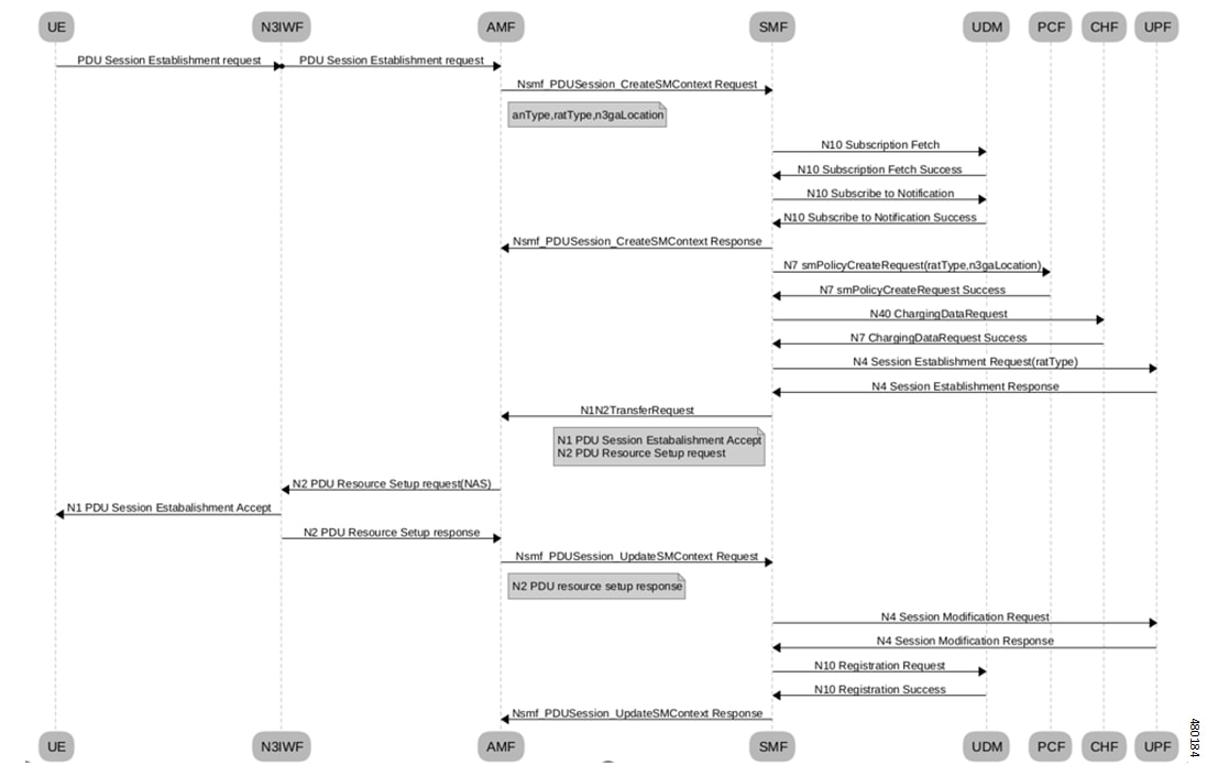
PDU session establishment over N3IWF
-
PDU session release over N3IWF
-
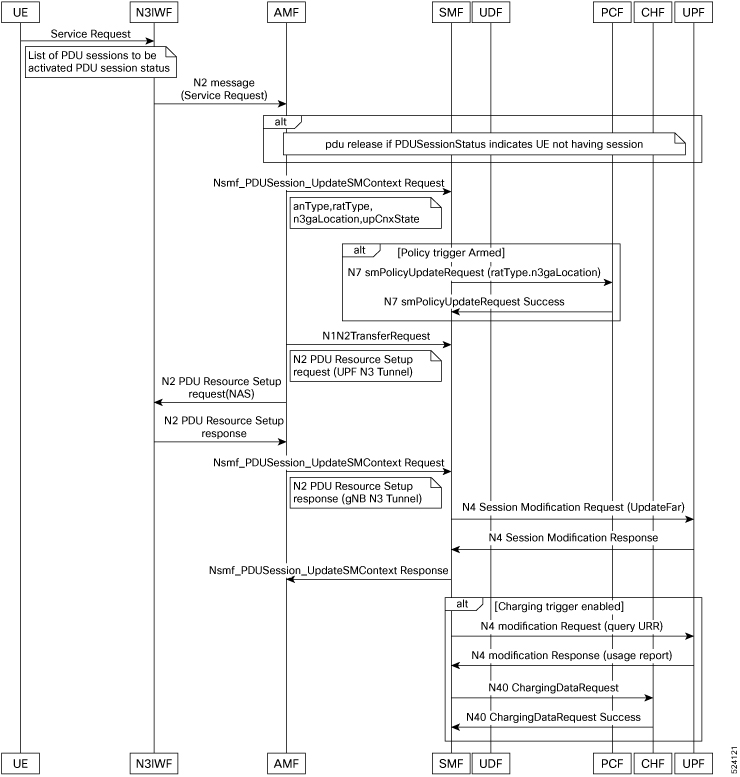
UE initiated service request through N3IWF
-
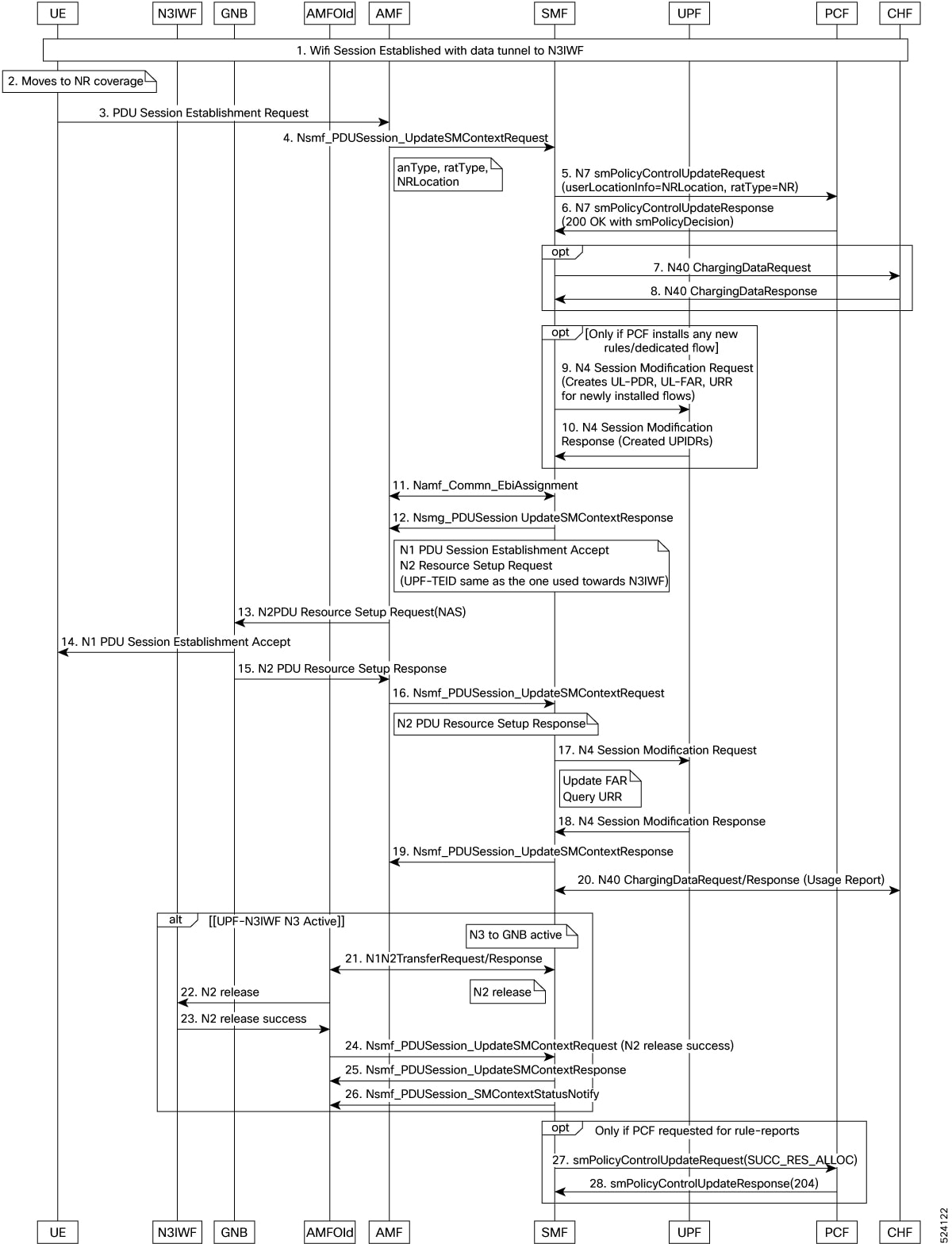
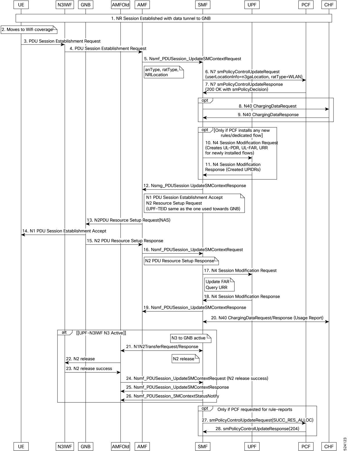
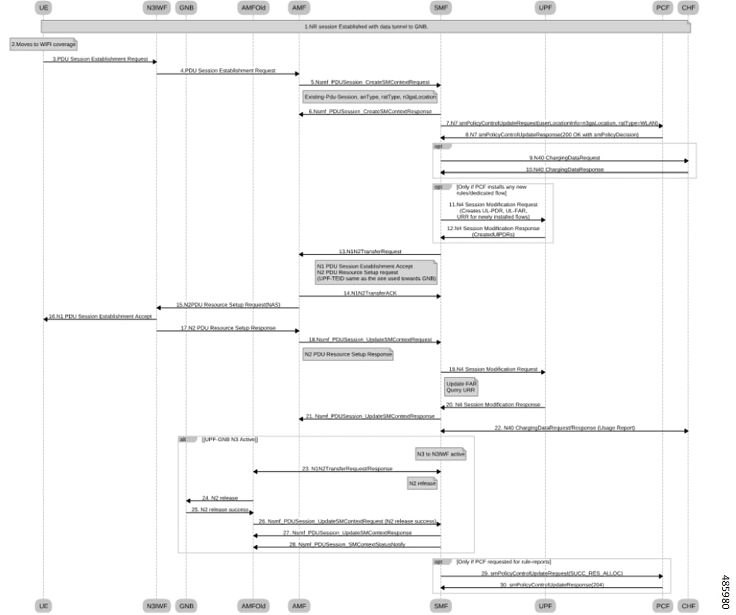
Intra PLMN Wi-Fi to NR HO through N3IWF
-
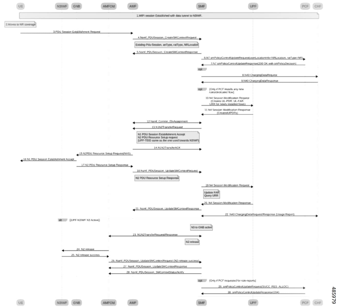
Intra PLMN NR to N3IWF Wi-Fi HO
-
Network initiated service request through N3IWF
-
Inter PLMN Wi-Fi to NR handover
-
Inter PLMN NR to Wi-Fi handover
-
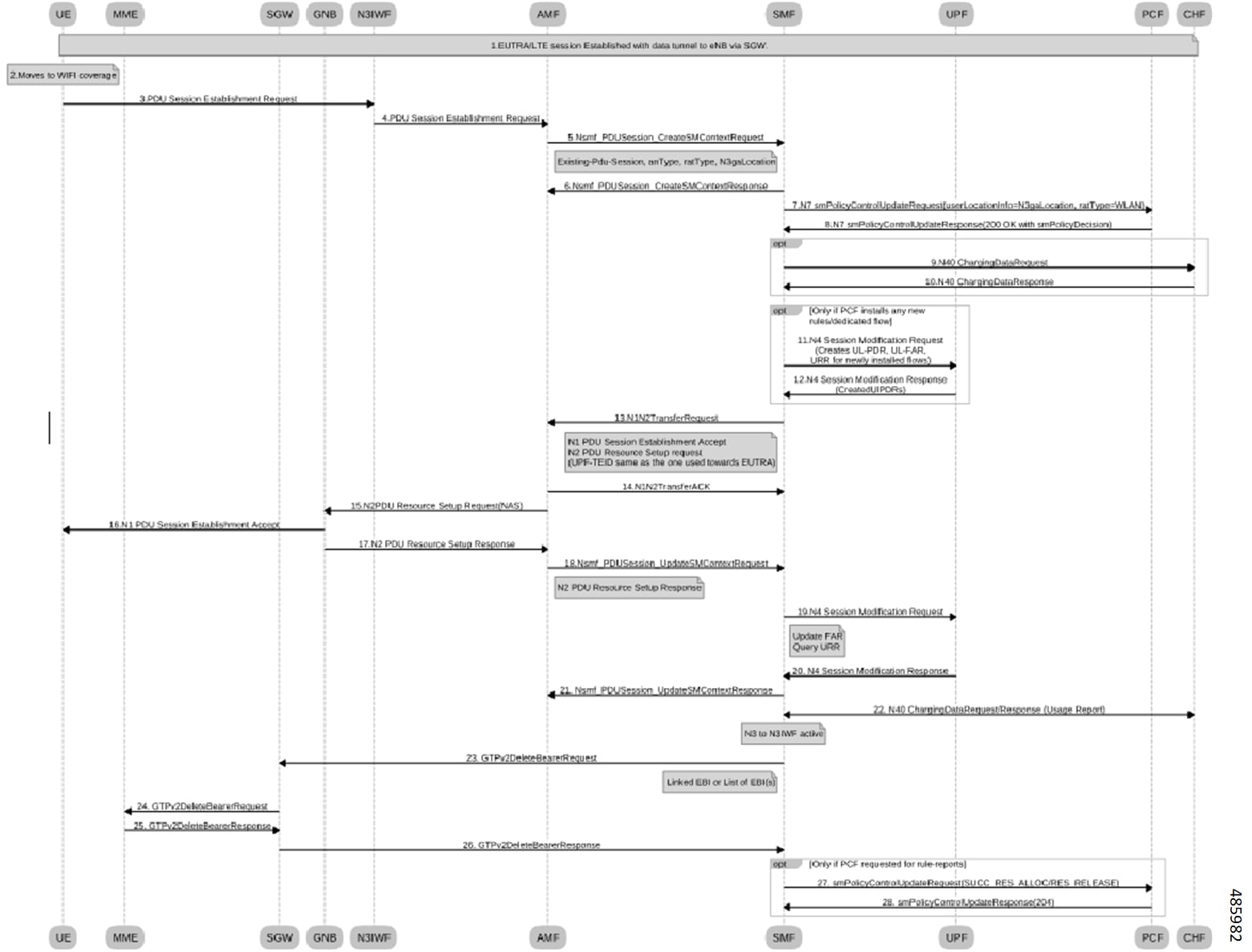
Wi-Fi (N3IWF) to Evolved Universal Terrestrial Radio Access (EUTRA) HO
-
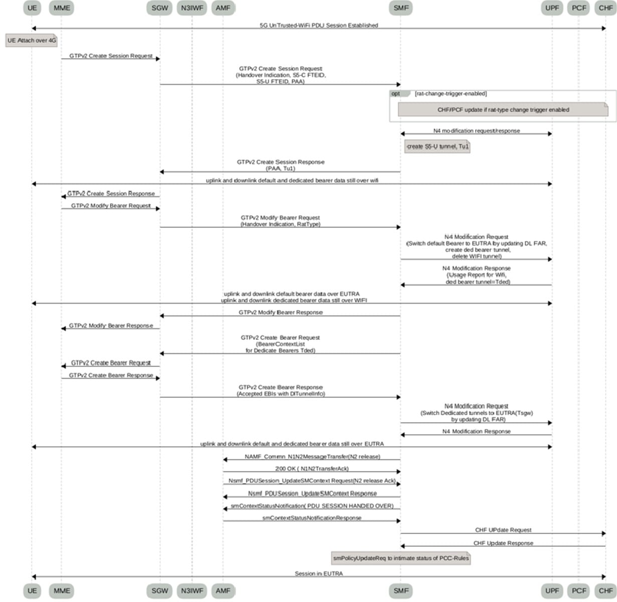
EUTRA to Wi-Fi (N3IWF) HO
-
Next Generation Core-Agnostic (N3GA) location parameters
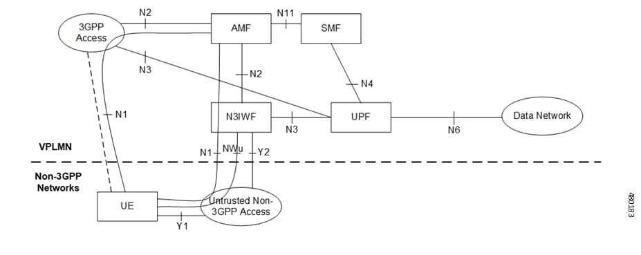
Architecture
The following figure represents the non-roaming architecture of 5G core network with untrusted non-3GPP access network.

 Feedback