RADIUS Client

Feature Summary and Revision History

Summary Data

Table 1. Summary Data
Applicable Product(s) or Functional Area SMF
Applicable Platform(s) SMI
Feature Default Setting Disabled – Configuration Required
Related Changes in this Release Not Applicable
Related Documentation Not Applicable

Revision History

Table 2. Revision History
Revision Details Release
First introduced. Pre-2020.02.0

Feature Description

In 5G architecture, the serving network authenticates the Subscription Permanent Identifier (SUPI) during authentication and key agreement between UE and the network. In addition, the secondary authentication is performed for data networks outside the mobile operator domain. For this purpose, various EAP-based authentication methods and associated credentials are among which the RADIUS protocol is one of the widely used authentication protocols.

The Remote Authentication Dial-In User Service (RADIUS) Client feature integrates with the SMF to enable the generic Cloud Native 5G RADIUS functionality for authentication purposes. When the RADIUS Client feature is enabled, the SMF performs secondary authentication with the configured external AAA server (for example, RADIUS Server) as per 3GPP TS 23.501.


Important

Only the RADIUS protocol is currently used for secondary authentication.


The RADIUS Client feature supports the following functions:

  • Server Selection

    RADIUS servers are configured with IP:Port as the key. The algorithm CLI specifies the fail-over or load balancing algorithm to select the RADIUS server to which the authentication or accounting request must be sent. Servers that are marked "dead" are not considered for selection until they are marked "alive". The supported algorithms are first-server and round-robin.

    • First-server — Specifies that the request must be sent to RADIUS server with the highest priority. If the server becomes unreachable, the request is sent to the server with the next highest configured priority. This is the default algorithm.

    • Round-robin — Specifies that the request must be sent based on load balancing in a circular queue manner. The server that is last used is stored to maintain the round-robin selection. The order of the list is based on the configured relative priority of the servers.

  • Monitor Server and Dead Server Detection

    Monitor Server revisits the server database and marks the server which has not received response beyond the configured "timeout" value after the first request is sent. The server is marked "dead" and remains in dead-state for seconds configured as "deadtime". After the "deadtime" elapses, the server's dead-variable is reset again to mark it as ready to process requests. If the server is still not reachable, it is marked "dead" as part of the next request response timeout.

  • Timeout and Retry

    After a server is selected and request is sent to the server, an entry is maintained in the request queue until response is received from the RADIUS server or until timeout occurs. Monitor Requests is called to check on the requests queue for response timeouts and retry. It walks through all the entries and checks if any request timeout value configured as "responseTimeout" is hit. For such requests, if the number of retries is less than the configured "maxRetries" value, the request is resent to the RADIUS server. Else, if the "maxRetries" count is reached, the request is deleted from the request queue. After a request is deleted, even if response comes for such requests, the response is discarded and not sent to the user.

Architecture

RADIUS Integration in Mobile CNAT Architecture

The Mobile CNAT architecture has four distinct layers:

  1. Cloud — Host OS + Kubernetes installation.

  2. Runtime — These are plugins to Kubernetes provided by the Cloud. This includes the container runtime (docker version) and Kubernetes plugins for volume (storage), networking, and load balancing.

  3. Orchestration — Kubernetes functionality. Kubernetes provides abstractions for provided plugins (networking, volumes, load balancing) so that the CNAT components need not have knowledge of them.

  4. Mobile CNAT Components — Application layer where the applications are built for mobility depending only on Kubernetes as much as possible.

For more details about the Mobile CNAT architecture, see the following link: https://wwwin-github.cisco.com/pages/mobile-cnat-infrastructure/architecture/arch/cnat_architecture.html

5GC Network Functions (NFs) run in the Application/CNAT Component layer of this architecture. RADIUS Client is an integral part of the SMF and PCF NFs.

RADIUS Client Integration in SMF

The SMF consists of loosely coupled micro-services. The micro-service decomposition is based on the following three-layered architecture:

  1. Layer 1: Protocol and Load Balancer services (stateless)

  2. Layer 2: Application services (stateless)

  3. Layer 3: Database services (stateful)

The RADIUS Client POD is integrated as part of the Protoco layer.

The following figure illustrates the integration of RADIUS Client in SMF.

Radius-EP App (RADIUS-Client POD) - The RADIUS Client functionality is added in a new POD. It handles RADIUS protocol-specific functions such as authentication and accounting.


Important

This release supports only RADIUS authentication.


SMF Service App (SMF Service POD) - The SMF Service App provides PDU session service. During session establishment, the SMF service decides if the secondary authentication is required or not, and acts accordingly.

UDP-Proxy App (UDP-Proxy POD) - The UDP-Proxy App is enabled with host-networking and, sends and receives packets using external Virtual-IPs. All RADIUS packets are transmitted and received from an outside cluster using this application.

How it Works

This section describes the authentication method applied by RADIUS.

RADIUS Authentication Method

RADIUS uses the following authentication methods:

  • User-Name - RADIUS supports only MSISDN-based user authentication. The GPSI or MSISDN value is set as the User-Name in RADIUS authentication requests (with stripped-off "msisdn-" string). The other methods such as PAP, CHAP, and MSCHAP are not supported in this release.

  • User-Password - The user password is the RADIUS server's "secret" key.

RADIUS Client - Dictionary

The dictionary file maps descriptive names to attribute numbers in a packet. Each packet contains an encoded version of an attribute. The encoded version is binary data and non-readable. It is also used to define data types for an attribute.

On the client side, the dictionary file is used to determine the attribute type, and encoding or decoding of attribute values based on the type. For example, the attribute is interpreted as a User-Name attribute of type string when the header contains Type field as 1. Each RADIUS attribute contains a header with Type, Length, and Value fields. For standard attributes, the type is fixed; for VSA attributes, the type is 26. For VSA attributes, there are two headers - the outermost is a normal RADIUS attribute header, and the inner header contains information such as VSAType, Length, Vendor-Id, and Attribute Value.

The dictionary file is defined based on the RFC .dct file format. The following is an example of the RADIUS dictionary file:

# radius standard attributes, vsa with enum values 
# format is based on rfc .dct files 
 
# Standard attributes 
ATTRIBUTE   User-Name                 Standard(1)              string 
ATTRIBUTE   User-Password             Standard(2)              octets 
ATTRIBUTE   Service-Type              Standard(6)              integer 
VALUE       Service-Type              Login-User               1 
VALUE       Service-Type              Framed-User              2 
VALUE       Service-Type              Callback-Login-User      3 
VALUE       Service-Type              Callback-Framed-User     4 
VALUE       Service-Type              Outbound-User            5 
VALUE       Service-Type              Administrative-User      6 
VALUE       Service-Type              NAS-Prompt-User          7 
VALUE       Service-Type              Authenticate-Only        8 
VALUE       Service-Type              Callback-NAS-Prompt      9 
VALUE       Service-Type              Call-Check               10 
VALUE       Service-Type              Callback-Administrative  11 
 
# VSA 
ATTRIBUTE   3GPP-IMSI                 3GPP-VSA(1)     string 
ATTRIBUTE   3GPP-IMSI-MCC-MNC         3GPP-VSA(8)     string 
ATTRIBUTE   3GPP-User-Location-Info   3GPP-VSA(22)    UeLocType 
ATTRIBUTE   3GPP-MS-Time-Zone         3GPP-VSA(23)    octets 

The first column denotes if the entry is an ATTRIBUTE or a VALUE to indicate an attribute or enum value of an attribute respectively. The second column contains the name of the attribute in case of both ATTRIBUTE and VALUE entries. For ATTRIBUTE entries, the third column denotes if the attribute is a standard attribute with attribute type number, and in case of VSA attribute, it contains the VendorName with vendor attribute type number. For VALUE entries, the third column contains the enum description. The last column denotes the data type of the attribute or the enum value of an attribute.

RADIUS Client – UDP Source Port Generation Logic

The following logic is used for generating a UDP source port.

3 Bits - Reserved for future use

6 Bits - Maximum number of 64 replica instances

7 Bits - Maximum number of 128 source ports per instance

x 256 IDs - Maximum number of 32 outstanding RADIUS requests per instance

13 Bits Total - Maximum number of 8000 source ports per instance

x 256 IDs - Maximum number of 2 million outstanding RADIUS requests per cluster

RADIUS Client – POD Replica Support

Multiple RADIUS PODs can be spawned based on the requirements. The pod replicas work as follows:

  • SMF Service requests are sent to any of the RADIUS POD using the cluster's load-balancing method. On receiving the request, the RADIUS POD initiates the access-request packet and uniquely reserves a UDP source port using the "instance-id" logic.

  • When the UDP-Proxy receives the response, it searches the actual instance of the RADIUS POD by decoding the UDP destination port value, and unicasts the packet to the respective RADIUS POD.

The following figure illustrates the working of the POD replica.

RADIUS Client – Attributes Encoding

The following attributes in the access-request packet are supported in this release.

ATTRIBUTE Reference Specification Encoding Type
USER-NAME RFC2865 - 5.1 String
PASSWORD RFC2865 - 5.2 Encrypted String
CALLING-STATION-ID RFC2865 - 5.31 String
CALLED-STATION-ID RFC2865 - 5.30 String
NAS-IP-ADDRESS RFC2865 - 5.4 IPv4 Address
NAS-IDENTIFIER RFC2865 - 5.32 String
SERVICE-TYPE RFC2865 - 5.6 Octets - 4 bytes
FRAMED-PROTOCOL RFC2865 - 5.7 Octets - 4 bytes
NAS-PORT-TYPE RFC2865 - 5.41 Octets - 4 bytes
NAS-PORT RFC2865 - 5.5 Octets - 4 bytes
3GPP-IMSI 3GPP 29.061 - 16.4.7.2-1 String
3GPP-CHARGING-ID 3GPP 29.061 - 16.4.7.2-2 Octets - 4 bytes
3GPP-PDP-TYPE 3GPP 29.061 - 16.4.7.2-3 Octets - 4 bytes
3GPP-CHARGING-GATEWAY-ADDR 3GPP 29.061 - 16.4.7.2-4 IPv4 Address
3GPP-GPRS-NEG-QOS-PROFILE 3GPP 29.061 - 16.4.7.2-5 Special Encoded Octets
3GPP 29.274 - 8.7
3GPP-SGSN-ADDRESS 3GPP 29.061 - 16.4.7.2-6 IPv4 Address
3GPP-GGSN-ADDRESS 3GPP 29.061 - 16.4.7.2-7 IPv4 Address
3GPP-IMSI-MCC-MNC 3GPP 29.061 - 16.4.7.2-8 String
3GPP-GGSN-MCC-MNC 3GPP 29.061 - 16.4.7.2-9 String
3GPP-NSAPI 3GPP 29.061 - 16.4.7.2-10 String
3GPP-SELECTION-MODE 3GPP 29.061 - 16.4.7.2-12 String
3GPP-CHARGING-CHARACTERISTICS 3GPP 29.061 - 16.4.7.2-13 String
3GPP-SGSN-MCC-MNC 3GPP 29.061 - 16.4.7.2-18 String
3GPP-IMEISV 3GPP 29.061 - 16.4.7.2-20 String
3GPP-RAT-TYPE 3GPP 29.061 - 16.4.7.2-21 Octet - 1 byte
3GPP-USER-LOCATION 3GPP 29.061 - 16.4.7.2-22 Special Encoded Octets
3GPP 29.274 - 8.21-4
3GPP 29.274 - 8.21-5
3GPP-MS-TIMEZONE 3GPP 29.061 - 16.4.7.2-23 Special Encoded Octets
3GPP 29.274 - 8.44
3GPP-NEGOTIATED-DSCP 3GPP 29.061 - 16.4.7.2-26 Octet - 1 byte
  • USER-NAME

    Description: String value encoded as per RFC 2865.

    • 5G call: GPSI value is used, with stripped-off "msisdn-"

    • 4G call: MSISDN value is used, with stripped-off "msisdn-"


      Note

      PAP, CHAP, and MSCHAP authentication methods are not supported in this release.


  • PASSWORD

    Description: Encrypted string value encoded as per RFC 2865.

    For both 5G and 4G calls, selected RADIUS server's "secret" is set as user-password.

  • CALLING-STATION-ID

    Description: String value encoded as per RFC 2865.

    5G call: GPSI value is used, with stripped of "msisdn-"

    4G call: MSISDN value is used, with stripped of "msisdn-"

  • CALLED-STATION-ID

    Description: String value encoded as per RFC 2865.

    For both 5G and 4G calls, DNN value is set as called-station-id.

  • NAS-IP-ADDRESS

    Description: IPv4 address value encoded as per RFC 2865.

    For both 5G and 4G calls, user-configured RADIUS Client interface-type's VIP-IP is used.

  • NAS-IDENTIFIER

    Description: String value encoded as per RFC 2865.

    For both 5G and 4G calls, user-configured nas-identifier attribute value is used.

  • SERVICE-TYPE

    Description: 4-byte Octet (int) value encoded as per RFC 2865.

    For both 5G and 4G calls, "FRAMED (2)" value is set.

  • FRAMED-PROTOCOL

    Description: 4-byte Octet (int) value encoded as per RFC 2865.

    For both 5G and 4G calls, "GPRS-PDP-CONTEXT (7)" value is set.

  • NAS-PORT-TYPE

    Description: 4-byte Octet (int) value encoded as per RFC 2865.

    For both 5G and 4G calls, "WIRELESS-OTHER (18)" value is set.
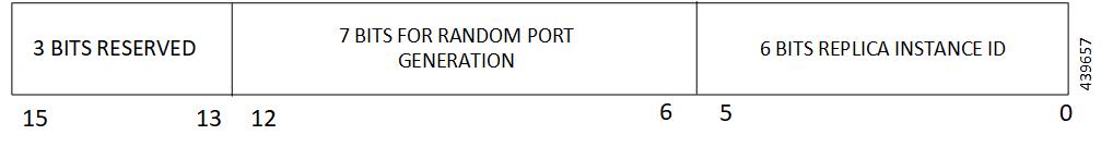
  • NAS-PORT

    Description: 4-byte Octet (int) value encoded as per RFC 2865.

    For both 5G and 4G calls, the base value of respective instance is used. That is:

    0x40 00 00 00 is set for replica-0

    0x40 00 00 01 is set for replica-1

  • 3GPP-IMSI

    Description: String value encoded as per 3GPP TS 29.061.

    5G call: SUPI value is used.

    4G call: IMSI value is used.

  • 3GPP-CHARGING-ID

    Description: 4-byte octet (int) value encoded as per 3GPP TS 29.061.

    For both 5G and 4G calls, charging-ID is set.

  • 3GPP-PDP-TYPE

    Description: 4-byte octet (int) value encoded as per 3GPP TS 29.061.

    For both 5G and 4G calls, pdp-type is set as follows:

    • 0 = IPv4

    • 2 = IPv6

    • 3 = IPv4v6

  • 3GPP-CHARGING-GATEWAY-ADDR

    Description: 4-byte octet (IPv4-address) value encoded as per 3GPP TS 29.061.

    For both 5G and 4G calls, charging gateway address is set.

  • 3GPP-GPRS-NEG-QOS-PROFILE

    Description: Octets (special encoding) value encoded as per 3GPP TS 29.061 and 29.274.

    For 5G call, the values from default-qos profile of the system are used and the encoding is performed as follows:

    Table 3. Non-GBR case
    1-2 <Release indicator>- = "15" (UTF-8 encoded)
    3 "-" (UTF-8 encoded)
    4-5 ARP (UTF-8 encoded)
    6-7 5QI (UTF-8 encoded)
    8-9 UL Session-AMBR length (UTF-8 encoded)
    10-m UL Session-AMBR (UTF-8 encoded)
    (m+1) - (m+2) DL Session-AMBR length (UTF-8 encoded)
    (m+3) – n DL Session-AMBR (UTF-8 encoded)
    Table 4. GBR case
    1-2 <Release indicator> = "15" (UTF-8 encoded)
    3 "-" (UTF-8 encoded)
    4-5 ARP (UTF-8 encoded)
    6-7 5QI (UTF-8 encoded)
    8-9 UL MFBR length (UTF-8 encoded)
    10-m UL MFBR (UTF-8 encoded)
    (m+1)-(m+2) DL MFBR length (UTF-8 encoded)
    (m+3)-n DL MFBR (UTF-8 encoded)
    (n+1)-(n+2) UL GFBR length (UTF-8 encoded)
    (n+3)-o UL GFBR (UTF-8 encoded)
    (o+1) – (o+2) UL GFBR length (UTF-8 encoded)
    (o+3) - p DL GFBR (UTF-8 encoded)

    For 4G call, the values from the default-qos profile of the system are used and the encoding is performed as follows:

    Table 5. Non-GBR case
    1-2 <Release indicator>- = "08" (UTF-8 encoded)
    3 "-" (UTF-8 encoded)
    4-5 ARP (UTF-8 encoded)
    6-7 5QI (UTF-8 encoded)
    8-11 UL Session-AMBR (UTF-8 encoded)
    12-15 DL Session-AMBR (UTF-8 encoded)
    Table 6. GBR case
    1-2 <Release indicator> = "08" (UTF-8 encoded)
    3 "-" (UTF-8 encoded)
    4-5 ARP (UTF-8 encoded)
    6-7 5QI (UTF-8 encoded)
    8-11 UL MBR (UTF-8 encoded)
    12-15 DL MBR (UTF-8 encoded)
    16-19 UL GBR (UTF-8 encoded)
    20-23 DL GBR (UTF-8 encoded)
  • 3GPP-SGSN-ADDRESS

    Description: 4-byte octet (IPv4-address) value encoded as per 3GPP TS 29.061.

    For 5G call, the AMF address is set.

    For 4G call, the S-GW address is set.

  • 3GPP-GGSN-ADDRESS

    Description: 4-byte octet (IPv4-address) value encoded as per 3GPP TS 29.061.

    For both 5G and 4G call, SMF-Service IP is set.

  • 3GPP-IMSI-MCC-MNC

    Description: String value encoded as per 3GPP TS 29.061.

    For 5G call, SUPIs MCC and MNC values are set.

    For 4G call, IMSIs MCC and MNC values are set.

    MCC is first 3 bytes, MNC is next 2 or 3 bytes.

    If MCC value is any of the following, then MNC will be of 3 bytes, else MNC will be of 2 bytes.

    300 302 310 311 312 313 316 334 338 342 344 346 348 354 356 358 360 365 376 405 708 722 732

  • 3GPP-GGSN-MCC-MNC

    Description: String value encoded as per 3GPP TS 29.061.

    For both 5G and 4G call, configured MCC and MNC value of SMF is used.

    MCC is first 3 bytes, and MNC is next 2 or 3 bytes.

  • 3GPP-SGSN-MCC-MNC

    Description: String value encoded as per 3GPP TS 29.061.

    For 5G call, AMFs MCC and MNC values are set.

    For 4G call, SGWs MCC and MNC values are set.

    MCC is first 3 bytes, and MNC is next 2 or 3 bytes.

  • 3GPP-NSAPI

    Description: String value encoded as per 3GPP TS 29.061.

    For 5G call, QFI value from the defaultQos profile is set.

    For 4G call, EPS bearer ID is set.

  • 3GPP-SELECTION-MODE

    Description: String value encoded as per 3GPP TS 29.061.

    For both 4G and 5G call, value is set to "0".

  • 3GPP-CHARGING-CHARACTERISTICS

    Description: String value encoded as per 3GPP TS 29.061.

    For both 4G and 5G call, generic charging character is set.

  • 3GPP-IMEISV

    Description: String value encoded as per 3GPP TS 29.061.

    For 5G call, PEI value is set.

    For 4G call, IMEI value is set.

  • 3GPP-RAT-TYPE

    Description: 1-byte octet encoded as per 3GPP TS 29.061.

    For 5G call, value "NR (10)" is set.

    For 4G call, value "EUTRAN (6)" is set.

  • 3GPP-USER-LOCATION

    Description: Special encoded octet value encoded as per 3GPP TS 29.061.

    For 5G call, the following encoding logic is used:

    1

    Location-Type

    Only TAI = 136

    Only NCGI = 135

    Both TAI + NCGI =137

    2-6

    TAI-Encoding (if present)

    7-14

    NCGI-Encoding (if present)

    TAI Encoding header:

    1 MCC digit 2 MCC digit 1
    2 MNC digit 3 MCC digit 3
    3 MNC digit 2 MNC digit 1
    4-5 TAC value

    NCGI Encoding header:

    1 MCC digit 2 MCC digit 1
    2 MNC digit 3 MCC digit 3
    3 MNC digit 2 MNC digit 1
    4 SPARE NCI
    5-8 NR Cell Identifier (NCI)

    For 4G call, the following encoding logic is used:

    1 Location-Type
    Only TAI = 128
    Only ECGI = 129
    Both TAI + ECGI =130
    2-6 TAI-Encoding (if present)
    7-13 ECGI-Encoding (if present)

    TAI Encoding header:

    1 MCC digit 2 MCC digit 1
    2 MNC digit 3 MCC digit 3
    3 MNC digit 2 MNC digit 1
    4-5 TAC value

    ECGI Encoding header:

    1 MCC digit 2 MCC digit 1
    2 MNC digit 3 MCC digit 3
    3 MNC digit 2 MNC digit 1
    4 Spare ECI
    5-7 EUTRAN Cell Identifier (ECI)
  • 3GPP-MS-TIMEZONE

    Description: Special encoded octet value encoded as per 3GPP TS 29.061.

    Timezone string (for example: -07:00+1) is encoded as two-byte value mentioned below:

    First byte timezone – NA

    Second byte daylight – two bits used (00-0, 01-+1, 10-+2, 11 – Unused)

    1 TIMEZONE
    2 DAYLIGHT SAVING 0, or +1 or +2
  • 3GPP-NEGOTIATED-DSCP

    Description: 1-byte octet encoded as per 3GPP TS 29.061

    For both 5G and 4G calls, DSCP configuration from DNN qos-profile configuration is used.

    Sub -> DNN profile -> QosProfile -> DSCPMap -> Qi5 value check -> ARP priority check

Call Flows

RADIUS Authentication Call Flow

The following figure illustrates the end to end call flow between the SMF server and Radius-EP.

Table 7. RADIUS Authentication Call Flow
Step Description

1

Bringing up Radius-POD: Add the respective endpoint configuration, with VIP-IP similar to Protocol-EP VIP-IP. Add the Radius-server information to the profile-Radius configuration.

2

Add the secondary authentication configuration to the required DNN profiles.

3

During session-bringup, the DNN profile checks if secondary authentication is enabled after successful UDM validation.

  • If authentication is not enabled, continue with PCF.

  • If authentication is enabled, send IPC to Radius-POD to authenticate the subscriber.

4 The Radius-POD prepares the Access Request packet that is destined to a configured Radius-server, sends the packet to UDP Proxy POD to proxy the packet out.
6 The UPD Proxy POD creates a socket (if not already present) and sends out the packet to the Radius-server.
7 The Radius-server validates the Access Request. If accepted, it responds with the Access Accept message. Else, it responds with the Access Reject message.
8 The UDP Proxy responds to the respective Radius-EP instance.
9 The Radius-EP instance validates the response, fetches the framed-IP (if present), and updates the SMF-service.
10 The SMF-service, upon successful response from Radius-EP, continues with the PCF flow. Else, the SMF-service disconnects from the subscriber.

Secondary Authentication Call Flow

The following flowchart explains the secondary authentication handling of 4G and 5G subscribers by the SMF-service.

After successful UDM Subscriber-Notification Response, the SMF-service invokes secondary authentication if enabled in the DNN-profile configuration. Currently, only the RADIUS method is supported. It does a sync-wait for RADIUS-response and continues with the PCF Create operation upon successful response. If secondary authentication fails, the subscriber is deleted.

Figure 1. Secondary Authentication

Standards Compliance

The RADIUS Client feature complies with the following standard:

  • RFC 2865: Remote Authentication Dial in User Service (RADIUS)

Limitations and Restrictions

The RADIUS Client feature has the following limitations:

  • AAA group concept is not supported.

    • Global RADIUS profile configuration is supported, which is applicable to all DNNs.

  • Authorization and Accounting is not supported.

  • User authentication based on PAP, CHAP, MSCHAP, and so on, is not supported. Only MSISDN-based user authentication is supported in this release.

  • RADIUS Client interfaces' VIP-IP is mandatory configuration for RADIUS Client to work.

  • Currently, only one VIP-IP is supported.

  • VIP-IP must be same as the UDP-PROXY PODs IP.

  • Currently, RADIUS POD-level VIP-IP is not applicable.

Configuring the RADIUS Client Feature

This section describes how to configure the RADIUS Client feature.

Configuring the RADIUS Client feature involves the following steps:

  1. Configuring RADIUS Server

  2. Configuring RADIUS Server Selection Logic

  3. Configuring RADIUS NAS-Identifier

  4. Configuring RADIUS Detect-dead-server

  5. Configuring RADIUS Dead-time

  6. Configuring RADIUS Max-retry

  7. Configuring RADIUS Timeout

  8. Configuring RADIUS POD

  9. Configuring RADIUS NAS-IP

  10. Configuring Secondary Authentication Method

Configuring RADIUS Server

This section describes how to configure the RADIUS server.

configure 
   profile radius 
      server ipv4_address auth_port 
         secret secret_key 
         priority priority_value 
         commit 

NOTES:

  • profile radius : Enters the RADIUS configuration mode.

  • server ipv4_address auth_port : Specifies the IPv4 address and authorization port of the RADIUS server.

  • secret secret_key : Specifies the secret key.

  • priority priority_value : Specifies the server priority.

  • commit : Commits the configuration.

Configuration Example

profile dnn intershat 
 ... 
 authentication secondary radius 
exit 

Configuring RADIUS Server Selection Logic

This section describes how to configure the RADIUS server selection logic.

configure 
   profile radius 
      algorithm first-server 
      algorithm round-robin 
      commit 

NOTES:

  • profile radius : Enters the RADIUS configuration mode.

  • algorithm first-server : Sets the selection logic as highest priority first. This is the default behavior.

  • algorithm round-robin : Sets the selection logic as round-robin order of servers.

  • commit : Commits the configuration.

Configuration Example

profile radius 
 server 1.2.3.4 1812 
  secret   $8$73a0i4G3ILj0Np+8tn2QOoWDj3QkB+oefPc2ZK6RE6A= 
  priority 1 
 exit 
 server 1.2.5.6 1812 
  secret   $8$VccEEUVou7m5ptA9WZRPR7KDmxQ/L3KlJ3QqgHjexkk= 
  priority 2 
 exit 
exit 

Configuring RADIUS NAS-Identifier

This section describes how to configure the RADIUS NAS-Identifier.

configure 
   profile radius 
      attribute nas-identifier value_in_string 
      commit 

NOTES:

  • profile radius : Enters the RADIUS configuration mode.

  • attribute nas-identifier value_in_string : Sets the NAS-identifier value that is used while encoding.

  • commit : Commits the configuration.

Configuration Example

profile radius 
 algorithm round-robin 
exit 

Configuring RADIUS Detect-dead-server

This section describes how to configure the RADIUS Detect-dead-server.

configure 
   profile radius 
      detect-dead-server response-timeout value_in_seconds 
      commit 

NOTES:

  • profile radius : Enters the RADIUS configuration mode.

  • detect-dead-server response-timeout value_in_seconds : Sets the timeout value that marks a server as "dead" when a packet is not received for the specified number of seconds. Default: 10 seconds.

  • commit : Commits the configuration.

Configuration Example

profile radius 
 attribute 
  nas-identifier CiscoSmf 
 exit 
exit 

Configuring RADIUS Dead-time

This section describes how to configure the RADIUS Dead-time.

configure 
   profile radius 
      deadtime value_in_minutes 
      commit 

NOTES:

  • profile radius : Enters the RADIUS configuration mode.

  • deadtime value_in_minutes : Sets the time to elapse between RADIUS server marked unreachable and when we can re-attempt to connect. Default: 10 minutes.

  • commit : Commits the configuration.

Configuration Example

profile radius 
 detect-dead-server response-timeout 100 
exit 

Configuring RADIUS Max-retry

This section describes how to configure the RADIUS retries.

configure 
   profile radius 
      max-retry value 
      commit 

NOTES:

  • profile radius : Enters the RADIUS configuration mode.

  • max-retry value : Sets the maximum number of times that the system will attempt retry with the RADIUS server. Default: 5.

  • commit : Commits the configuration.

Configuration Example

profile radius 
 deadtime 15 
exit 

Configuring RADIUS Timeout

This section describes how to configure the RADIUS Timeout.

configure 
   profile radius 
      timeout value_in_seconds 
      commit 

NOTES:

  • profile radius : Enters the RADIUS configuration mode.

  • timeout value_in_seconds : Sets the time to wait for response from the RADIUS server before retransmitting. Default: 3 seconds.

  • commit : Commits the configuration.

Configuration Example

profile radius 
 max-retry 2 
exit 

Configuring RADIUS POD

This section describes how to configure the RADIUS POD.

configure 
   endpoint radius-dns 
      replicas number_of_replicas 
      commit 

NOTES:

  • endpoint radius-dns : Enters the endpoint radius-ep configuration mode.

  • replicas number_of_replicas : Sets the number of replicas required.

  • commit : Commits the configuration.

Configuration Example

profile radius 
 timeout 4 
exit 

Configuring RADIUS NAS-IP

This section describes how to configure the RADIUS NAS-IP

configure 
   endpoint radius-dns 
      interface radius-client 
         vip-ip ipv4_address 
         commit 

NOTES:

  • endpoint radius-dns : Enters the endpoint radius-ep configuration mode.

  • interface radius-client : Enters the radius-client interface-type configuration mode.

  • vip-ip ipv4_address : Sets the NAS-IP value, which is also used as the source-IP in UDP requests towards the RADIUS server.

  • commit : Commits the configuration.

Configuration Example

endpoint radius-dns 
 replicas 3 
exit 

Configuring Secondary Authentication Method

This section describes how to configure the secondary authentication method.

configure 
   profile dnn dnn_name 
      authentication secondary radius 
      commit 

NOTES:

  • profile dnn dnn_name : Enters the DNN Profile configuration mode.

  • authentication secondary radius : Enables secondary-authentication under the DNN profile and sets method as RADIUS.

  • commit : Commits the configuration.

Configuration Example

endpoint radius-dns 
interface radius-client 
  vip-ip 10.86.73.89 
 exit 
exit 

RADIUS Client OA&M Support

This section describes operations, administration, and maintenance information for this feature.

Statistics

Following statistics are available related to RADIUS functionality:

  • SMF-Service:

    • Number of Secondary-Authentication requests sent

    • Number of Secondary-Authentication response received

  • RADIUS-EP:

    • Number of Secondary-Authentication requests sent

    • Number of Secondary-Authentication response received

    • Number of RADIUS packets sent

    • Number of RADIUS packets received