- Preface
- Product Overview
- Getting Started
- Deploying Cisco Mobility Express Solution
- Creating DHCP Scopes for Wireless Networks
- Configuring Mobility Express for Site Survey
- Creating Wireless Networks
- Managing WLAN Users
- Managing Access Points
- Managing the Mobility Express Network
- Using Advanced Settings
- Primary AP Failover and Electing a New Primary
- Cisco Mobility Express with Cisco CMX Cloud
- Managing Mobility Express Deployments from Cisco Prime Infrastructure
Using Advanced
Settings
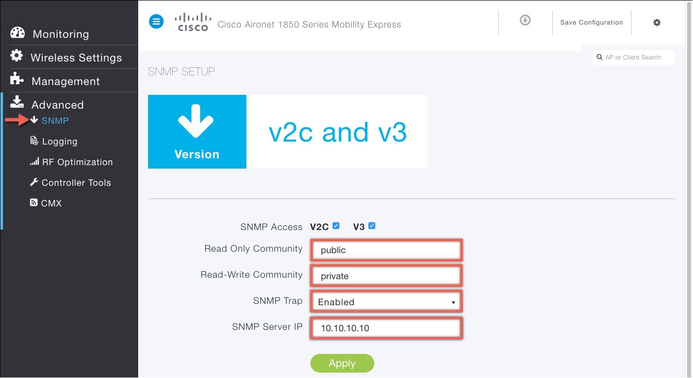
SNMP
Simple Network Management Protocol is a protocol for network management. It is used for collecting information from, and configuring, managing all the devices in the network.
Cisco Mobility Express supports SNMP Version 2 and SNMP Version 3. Both SNMP v2c and v3 are enabled by default. SNMP Version 1 is also supported on Mobility Express but enabling and disabling on SNMP Version 1 is available in CLI only.
Managing SNMP Version 2c
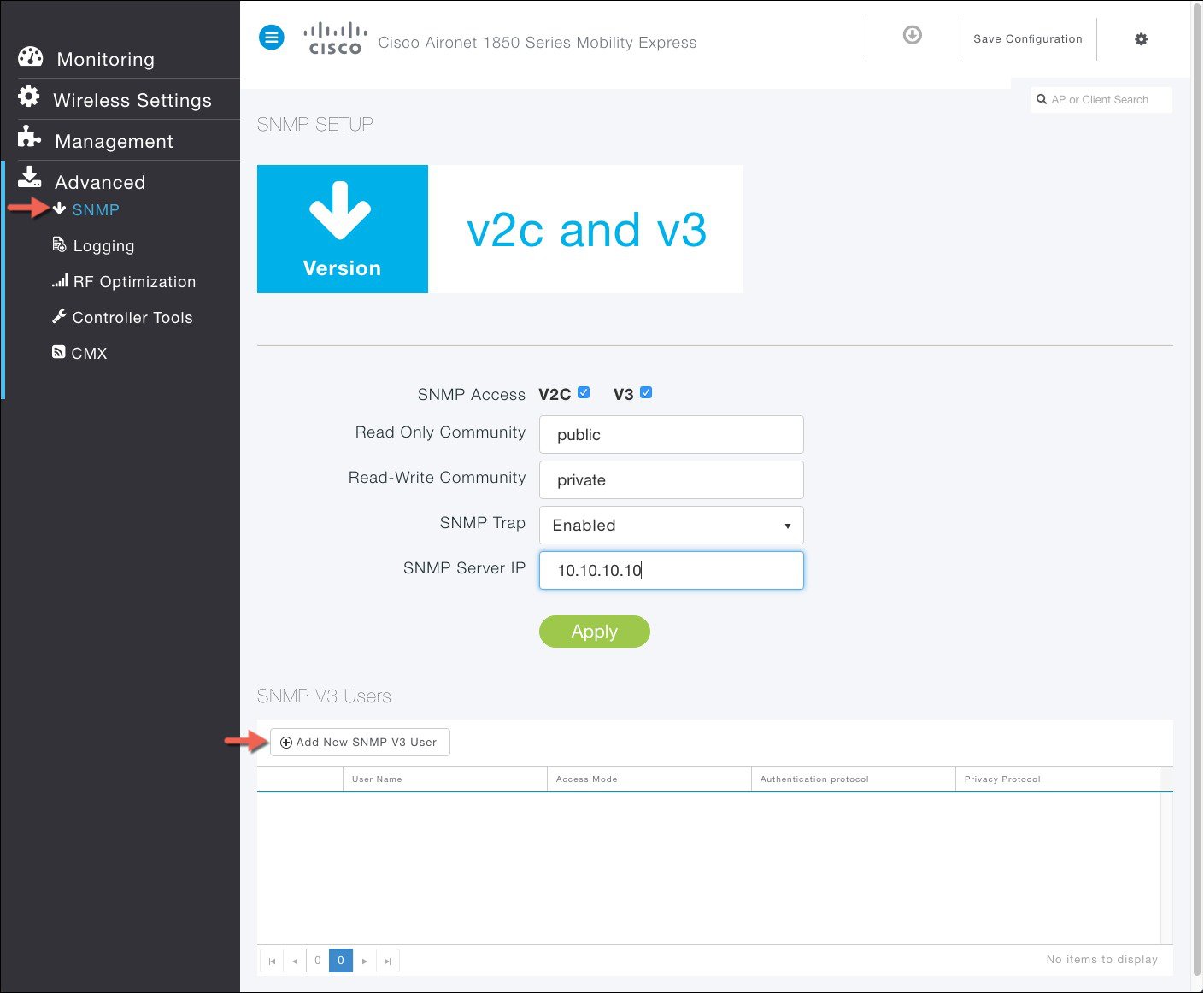
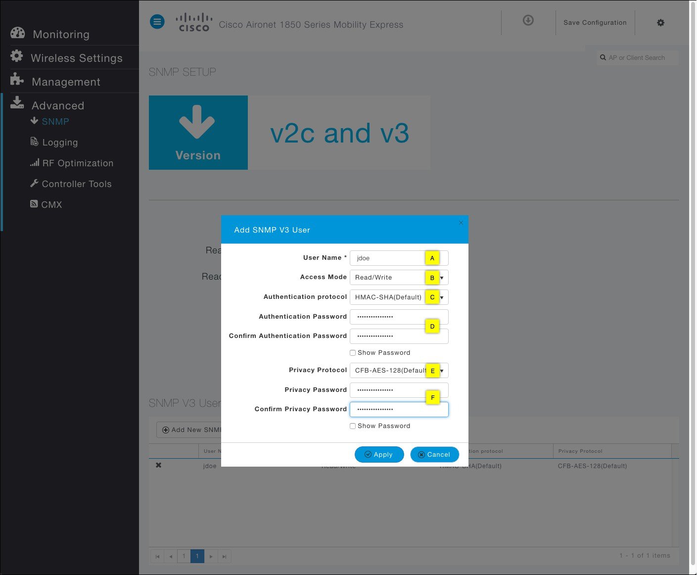
Managing SNMP Version 3 users
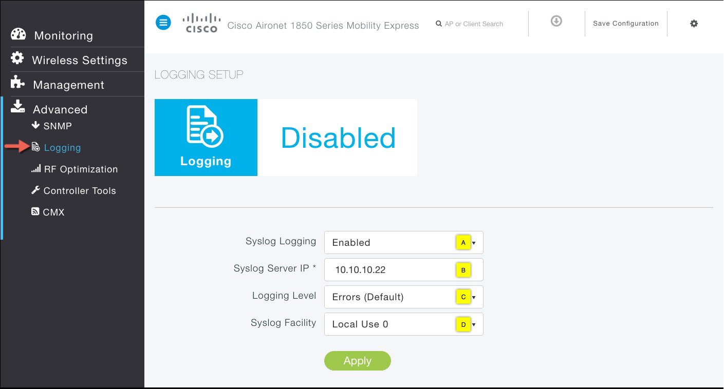
Logging
The System Message logging feature logs the system events to a remote server, called a Syslog server. Each system event triggers a Syslog message containing the details of that event.
If the System Message logging feature is enabled, the controller sends a syslog message to the syslog server configured on the controller.
To configure Logging on Cisco Mobility Express, follow the procedure below.
RF Optimization
RF Optimization has control knobs for Client Density and Traffic Type in the Mobility Express deployment. Typically, RF Optimization is enabled and Client Density and Traffic Type is configured during the initial Setup Wizard when deploying Cisco Mobility Express. However, it can modified by following the steps below.
Controller Tools
The Controller Tools enables admin users to Restart the controller, clear the controller configuration and set the Mobility Express network to Factory Default, and Export and Import Controller configuration files.
Restart Controller
Clear Controller Configuration
You can change the Mobility Express network to its default configuration by clearing the controller configuration and performing Reset to Factory Default.
 Note |
|
Export and Import of Controller Configuration File
One can export or import Mobility Express controller configuration file. To export the active controller configuration file, follow the steps below:
Exporting Controller Configuration File
Importing Controller Configuration File
| Step 1 | Navigate to Advanced > Controller Tools. | ||
| Step 2 | Click on the Import Configuration Button. | ||
| Step 3 | In the Import Configuration window, click on the Choose File button and browse to the configuration file on your local device. | ||
| Step 4 | Click the Yes button to initiate the HTTP upload of the
configuration file. You will see import status messages being displayed on top
of the window.
|
Export of Logs, core and crash files
Cisco Mobility Express provides a simplified way to collect and bundle all the necessary files for TAC. This bundle can then be transferred to a TFTP or FTP server.
The following files are collected from the Controller:
- ap-crash-data—Upload the ap-crash files.
- config—Upload the system's configuration file.
- coredump—Upload the system's Core Dump.
- crashfile—Upload the system's crash file.
- debug-file—Upload the system's debug log file
- run-config—Upload the controller's running configuration
- systemtrace—Upload the system's trace file.
- traplog—Upload the system's msglog and traplog collected before previous system reset.
- errorlog—Upload the system's error log.
- radio-core-dump—Upload the ap-radio core dump files
The following files are collected from an Access Point:
- show tech-support
- /var/log/messages
- /var/log/messages.0
- /var/log/crash_log
- /storage/base_capwap_cfg_info
- /storage/config.*
- /proc/meminfo
- /proc/*/status
To generate the bundle with the files, follow the steps below:
| Step 1 | Set the data-type to support-bundle.
(Cisco Controller) >transfer upload datatype support-bundle |
| Step 2 | Set the transfer upload mode to tftp or ftp.
(Cisco Controller) >transfer upload mode tftp |
| Step 3 | Set the Set the TFTP
server ip .
(Cisco Controller) >transfer upload serverip <server ip> |
| Step 4 | Set the
path
on TFTP server.
(Cisco Controller) >transfer upload path <tftp path> |
| Step 5 | Set the
file name.
(Cisco Controller) >transfer upload filename <file name> |
| Step 6 | Initiate the transfer.
(Cisco Controller) >transfer upload start |
 Feedback