GNSS Best Practices for AFC and Cisco Wireless AP Location Deployments
Available Languages
Bias-Free Language
The documentation set for this product strives to use bias-free language. For the purposes of this documentation set, bias-free is defined as language that does not imply discrimination based on age, disability, gender, racial identity, ethnic identity, sexual orientation, socioeconomic status, and intersectionality. Exceptions may be present in the documentation due to language that is hardcoded in the user interfaces of the product software, language used based on RFP documentation, or language that is used by a referenced third-party product. Learn more about how Cisco is using Inclusive Language.
- US/Canada 800-553-2447
- Worldwide Support Phone Numbers
- All Tools
 Feedback
 Feedback
Document History
April 17, 2026
● Updated supported models
March 31, 2026
● Latest version
November 22, 2024
● Initial version
GNSS Deployment Best Practices
The use of 6-GHz Standard Power requires Automated Frequency Coordination (AFC). AFC provides a coordinated channel and power to a Standard Power-mode network to ensure Wi-Fi services do not interfere with incumbent services in the 6-GHz space. For more information about AFC, see the Automated Frequency Coordination guide for cloud and on-premises deployments.
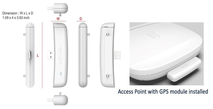
As per FCC regulations, access points (APs) operating at Standard Power must automatically obtain geolocation coordinates using an external or internal Global Navigation Satellite System (GNSS) module. The AP’s location is obtained automatically through the CW-ACC-GPS1, a GNSS module that attaches to the USB port of any Cisco Wireless 6E AP.
Once installed, position the AP on the floor of a building near a window with a clear line of sight to the sky. Within 10 minutes, the GNSS module acquires a satellite signal and shares the AP's location with the Cisco Catalyst 9800 Series Wireless Controllers or the Cisco Meraki dashboard. When connected to an external antenna, the module acquires satellite signals from up to 32 satellites, which are used to compute GPS location, constellation, orientation, and time.
Key operational stability requirements when planning a site deployment for 6 GHz Standard Power are GNSS signal health and satellite distribution. GNSS signal health and quality vary depending on the GNSS module’s location within a floorplan. Before enabling Standard Power operation within a floorplan, it is crucial to identify installation points within a building where the module receives a stable GPS reception. It is essential to determine the placement and quantity of GNSS modules for a floor plan to ensure stable Standard Power operation.
This guide provides a comprehensive approach to deploying GNSS modules for AFC and AP location services, focusing on optimizing GNSS module performance. The goal is to ensure reliable and stable satellite signal reception by identifying optimal locations and implementing necessary adjustments in the field.
Firmware Requirements
● Cisco Catalyst 9800 Series Wireless Controllers running Cisco IOS XE 17.14.1 or a later release
● Cisco Meraki networks running MR 30.7 or a later release
Supported APs
For the list of supported APs navigate to section GNSS/GPS Support in the AP Feature Matrix. The table applies for on-prem and cloud APs.
Additionally, MR57 is supported.
Installation
Identify potential locations in a floor plan that provide the best signal health and stability for GNSS modules. The number and signal strength of satellites the GNSS module can detect over 24 hours is a key metric for evaluating ideal GNSS installation points.
Geolocation Propagation
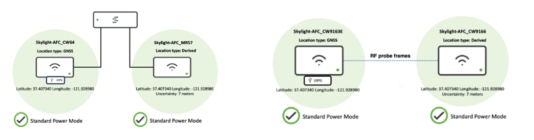
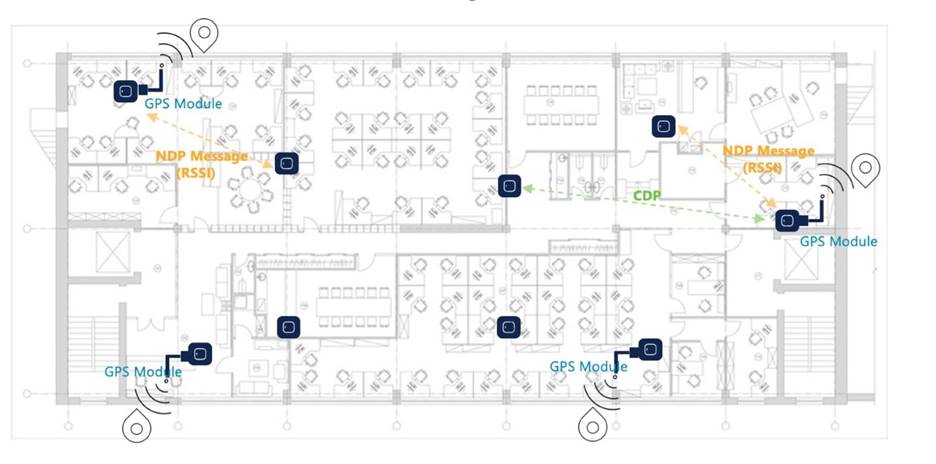
To conduct a preliminary GNSS site survey, it is recommended to have at least four modules to scope the proposed placement of APs on a floor plan, and the signal quality each module receives. If at least one AP nearby has a valid GPS signal, other neighboring APs can leverage the same GPS coordinates with a relative measure of uncertainty. This process is known as geolocation propagation. It can be accomplished through wired proximity on the same Layer 2 switch stack or shared RF neighborship up to a calculated distance of up to 400 meters from an AP with a valid GPS signal.
Wireless propagation allows neighboring APs to see an AP with GNSS reception as its neighbor by hearing beacon frames and NDP messages transmitted on any band or radio. For best results, the stronger the RF neighborship, the more consistent the results will likely be. If the neighborship is weak and close to the noise floor, then the deployment is likely prone to gaps in Standard Power operation. Weak RSSI in the AP neighborship would cause the AP to be susceptible to other variables that can hinder performance or limit geolocation propagation at any given time.
Target an RF neighborship of an RSSI of at least -75 dBm or better on any one of the 2.4 GHz, 5 GHz, or 6 GHz bands and an SNR of 15-20 or better for optimal and consistent results. Results vary from one wireless environment to the next.
For GNSS APs to share their location via wired propagation, they need to be seen as neighbors in the CDP or LLDP table, confirming that they are connected to the same Layer 2 network. This neighborship gives a wired distance between APs.
GPS Signal Lock
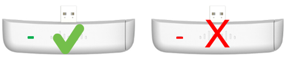
For the GNSS module to obtain a GPS signal, the AP must be powered on and have its USB port enabled. The USB port can be enabled either in the AP join profile on the wireless controller or the Meraki dashboard port profile. After 10 minutes, the GNSS module attempts to retrieve a satellite signal, and the LED on the side of the module blinks green. The LED transitions to solid green once the module obtains the GPS signal.
For the GNSS module to achieve a stable GPS lock, the module must be in sight of at least four satellites. However, for greater location accuracy, it is advised to have a reception of 6-8 satellites at any given time. If an AP’s internal or external GPS module acquires a signal, then the location type indicates “GNSS”. If the AP uses wired or wireless geolocation propagation techniques to obtain location from a neighboring GNSS AP, then its location type indicates “Derived”.
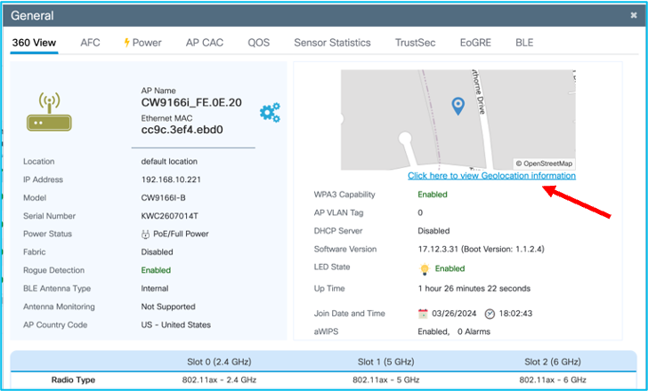
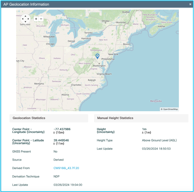
For Cisco Catalyst 9800 Series Wireless Controller-based deployments, the AP’s Location Type can be found by navigating to General > 360 View > Click here to view Geolocation Information > AP Geolocation Information or under Edit AP > Geolocation.
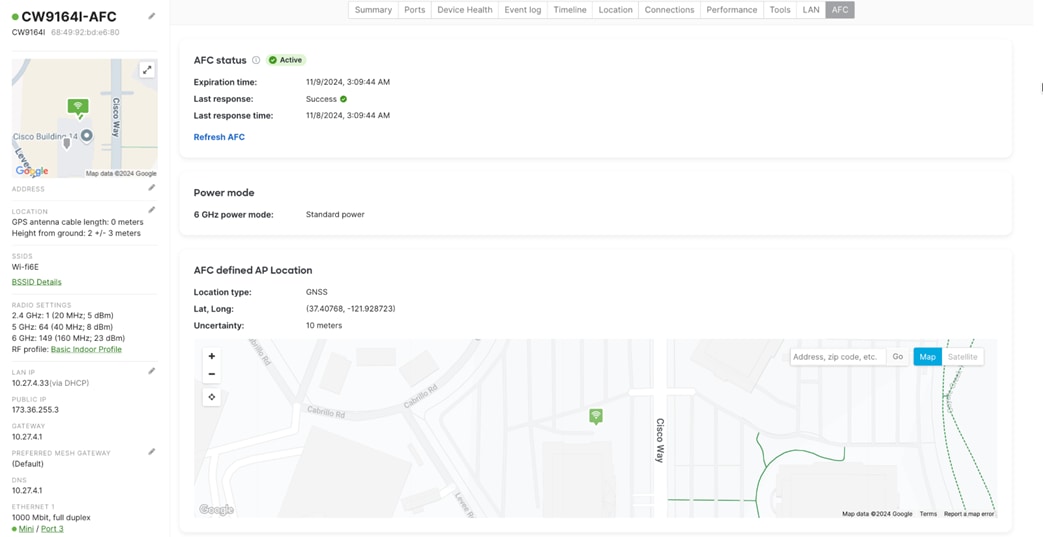
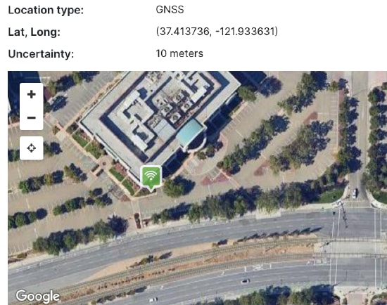
In the dashboard, from the AP’s overview page, go to the AFC tab. In the AFC defined AP Location section, you can find details of the AP’s GNSS location such as:
● the Location Type,
● its coordinates (latitude and longitude), and
● the level of Uncertainty in its positioning.
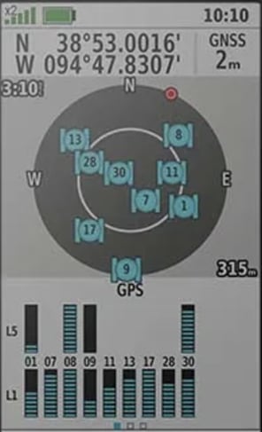
Currently, the dashboard does not report the number of satellites the GNSS module sees at any given time. During a preliminary site visit, it is advised to use a handheld GPS receiver to see the expected satellite constellations and relative signal strength the modules receive at a planned installation point.
After identifying possible installation points, ensure that the GNSS module can maintain a stable GPS lock with at least 6-8 satellites over a 15-minute window. A location that maintains a stable lock with six or more satellites during this period is likely to remain stable over 24 hours, ensuring consistent 6-GHz Standard Power operation.
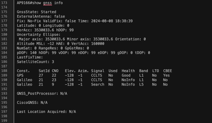
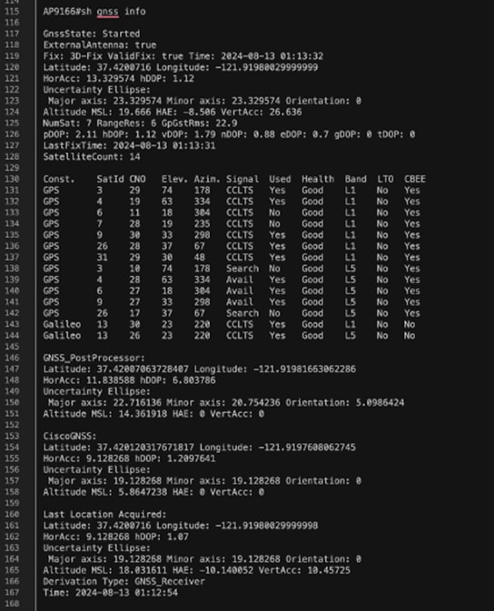
For controller-based GNSS deployments, run the show gnss info command on the AP’s CLI to assess the real-time availability and attributes of satellites seen by the AP’s GNSS module. This command provides information about the number of satellites the GNSS module detects, the constellation pattern, position, and signal health.
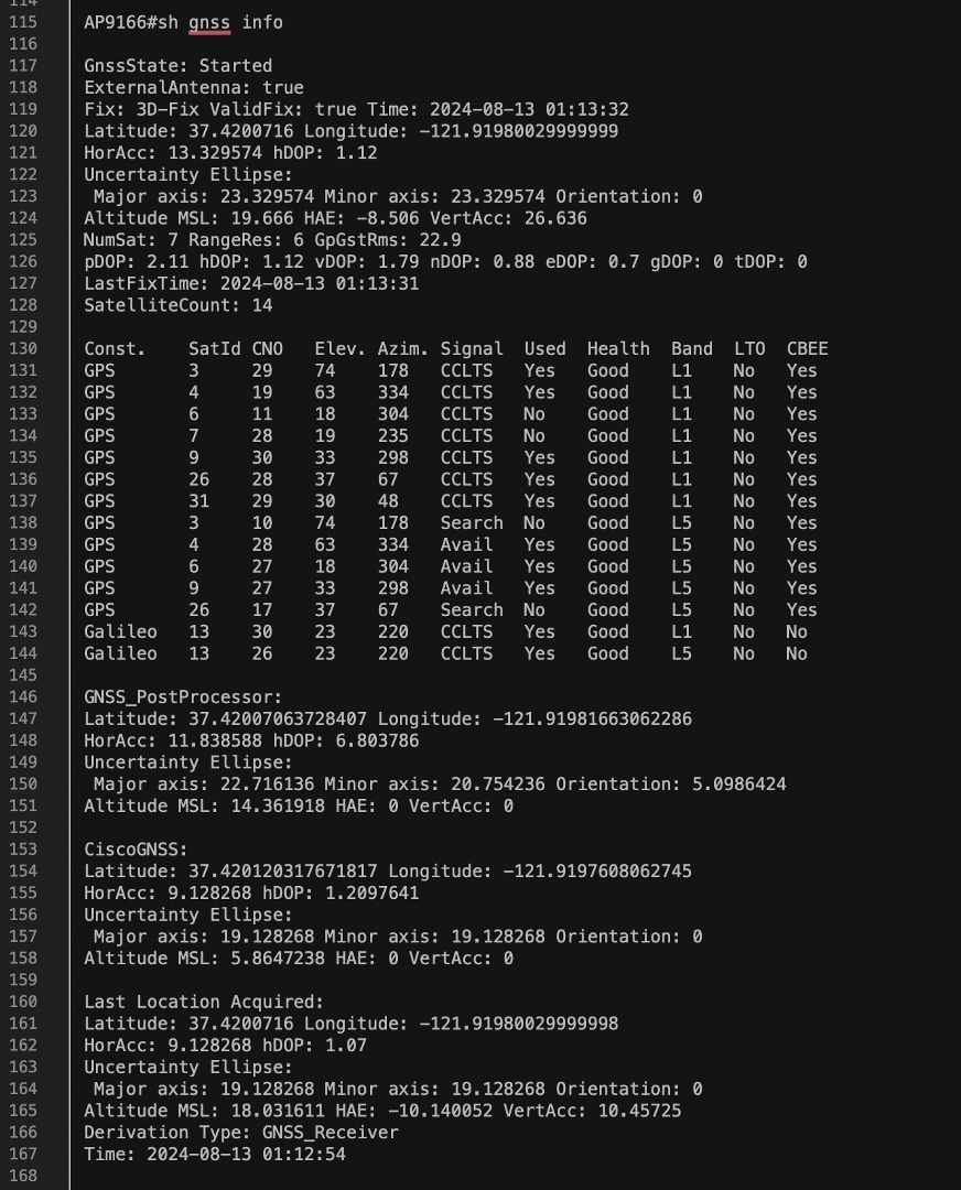
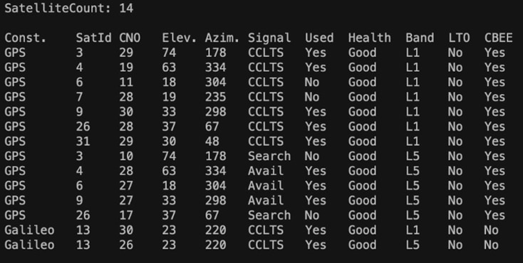
In the SatelliteCount subsection of the command output, the current count of satellites visible to the GNSS module along with the satellite constellation is listed.
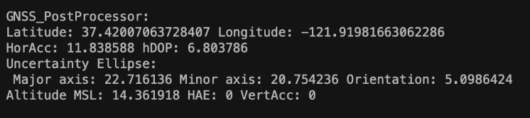
The GNSS_Post Processor subsection of the command output lists the collective readings of reported satellites by the GNSS module. These readings are aggregated to determine the precise location of the GNSS module along with a measured level of uncertainty.
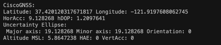
The CiscoGNSS subsection of the command output shows the satellite measurements calculated by the Cisco GNSS Processor. These measurements are obtained by fine tuning the GNSS Post Processor output over 24 hours.
GNSS Signal Considerations
If the number of satellite constellations visible is less than four, then the GNSS module experiences unstable satellite reception. If more than four satellites are detected in a constellation but no GNSS signal is received, then poor signal health is likely the issue. Reposition the AP within the floor plan to improve the GNSS module’s line of sight to the sky.
Note: Satellite distribution plays a critical role in the AFC location process. Better accuracy is achieved when satellites are widely distributed rather than clustered together. While satellite distribution cannot be influenced, installing the GNSS module with a broader view of the sky improves the satellite lock.
When conducting the preliminary site assessment, it is essential to consider potential sources of interference in the environment. Transmit and receive radio signals are susceptible to RF obstructions and common sources of interference that can reduce or reflect satellite signals the GNSS module can receive.
Select install locations away from metal obstructions such as heating and air-conditioning ducts, large ceiling trusses, building superstructures, and significant power cabling runs.
Building glass with UV filtering film completely blocks the GPS signal from reaching the module for indoor GNSS deployments. In cases where the signal is significantly degraded, you can improve GNSS reception by attaching the CW-ANT-GPS1-M-00 external antenna to the GNSS module.
CW-ANT-GPS1-M-00 Overview
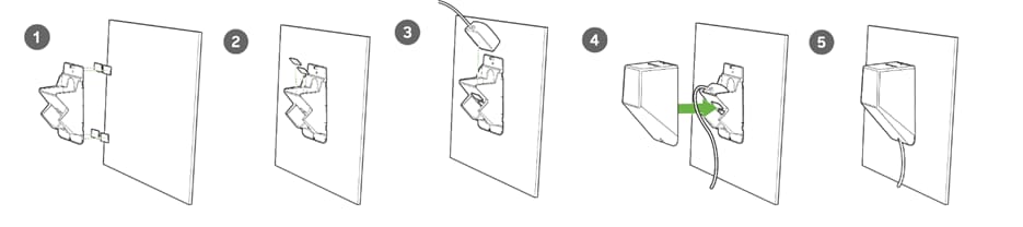
The CW-ANT-GPS1-M-00 external antenna is designed for use with the CW-ACC-GPS1 accessory module. Mount the antenna such that there are no obstructions to the sides of the radiating elements. Generally, the higher an antenna is above the floor, the better it performs. Find a mounting place directly above your wireless device to ensure the lead-in cable is as short as possible.
There are also some AP models that support directly connecting the antenna to the AP. The CW-ACC-GPS1 accessory is therefore not needed in those cases, for the list please check the AP Feature Matrix.
Connect the antenna to the AP using the MMCX connector and the 32.80-ft. (10 m) plenum cable.
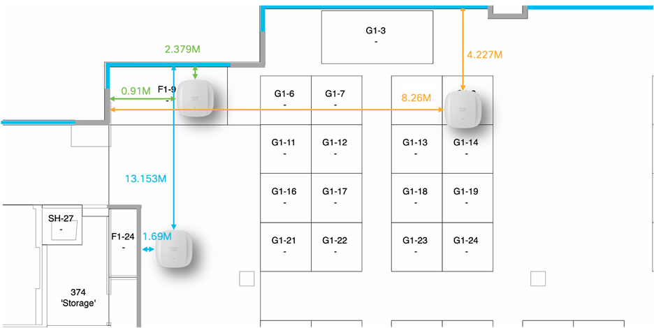
GNSS modules positioned around 13 meters inside a carpeted building register an average satellite count of 3. This limited signal reception results in the GNSS module being unable to maintain a stable GPS lock. To extend the module’s reception range in such scenarios, use the CW-ANT-GPS1-M-00 external antenna. Once the external antenna is securely attached to the GNSS port located on the left side of the CW-ACC-GPS1, the GNSS module should receive more satellite constellations, allowing for stable GPS reception.
Signal reception is immediately improved when the antenna is attached to the GNSS module, as the antenna receivers provide stronger GNSS reception than the module alone. Route the antenna up to 10 meters to a secondary installation point from the AP to clear line of sight to the sky.
The output of the show gnss info command in the figures below highlights the enhanced signal reception the GNSS module can achieve with an attached CW-ANT-GPS1-M-00 external antenna.
Conclusion
See the documents listed in the Learn More section for more information about monitoring AP location data on the Cisco Catalyst 9800 Wireless Controller and Meraki Dashboard. These guidelines and best practices help you identify and maintain optimal GNSS module placement, ensuring consistent signal quality and reliability for long-term 6-GHz Standard power operation and AP AnyLocate deployments.
Learn More