Q. What is AFC?
A. Automated Frequency Coordination (AFC) is an advanced cloud-based system for coordinating spectrum sharing with incumbents in the 6-GHz band. AFC allows Cisco
® Wi-Fi 6E and Wi-Fi 7 access points to operate at standard power in the 6-GHz band, both indoors and outdoors.
Q. What is standard power?
A. Standard Power (SP) is a class of wireless LANs that allows access points to operate at a maximum transmit power (Effective Isotopic Radiated Power, or EIRP) of 36 dBm and a maximum spectral density of 23 dBm per MHz in the unlicensed 6-GHz band using AFC. The FCC requires outdoor access points to operate in SP mode when using the 6-GHz band. Indoor access points can operate in both SP and Low Power Indoor (LPI) modes.
Q. Which Cisco platforms and versions support AFC?
A. Automated Frequency Coordination (AFC) is supported by both Cisco Catalyst
™ and Meraki
® wireless stacks. Specifically:
● For Cisco Catalyst access points, AFC support is available starting with Cisco IOS® XE version 17.12.3.
● For Meraki access points, AFC support is available starting with firmware release MR 30.7+ firmware release.
Q. Which access points support the AFC feature?
A. All Cisco Wi-Fi 6E and Wi-Fi 7 Access Points are standard power certified by the FCC and support AFC. For exact model please refer to documentation.
● Catalyst
● Meraki
Q. Which Wi-Fi 7 access points support the AFC feature?
A. Indoor access points
● CW9172I
● CW9172H
● CW9176I
● CW9176D1
● CW9178I
Outdoor access points
● CW9179F
Q. Which licenses are required for the AFC feature?
A. AFC is available as part of Cisco DNA Essentials for Catalyst and Meraki Enterprise for Meraki.
Q. Does standard power require configuration?
A. The Catalyst 9163E outdoor access point has standard power service enabled by default in Catalyst management mode. When using Meraki management mode, standard power needs to be enabled. For other access points, standard power should be enabled based on customer needs. Height parameters must be manually configured for indoor and outdoor access points.
Note: Outdoor access points operating in the 6-GHz band are not allowed to use LPI mode; standard power is required for outdoor 6-GHz operation.
Q. How is standard power enabled?
A. The feature is configured on the Cisco Catalyst 9800 Series Wireless Controllers and Meraki dashboard by enabling standard power under the 6-GHz Radio Frequency (RF) profile and by configuring the height parameters of the access points. These settings can be configured via the WebUI or command-line interface. Standard power RF profiles can be assigned to specific access points as needed.
Geolocation information is obtained from a Global Navigation Satellite System (GNSS) module or through geolocation propagation techniques.
Note: The Catalyst 9800 Series Wireless Controllers need cloud connectivity to access the AFC service. No additional configuration is required to reach the AFC service except basic IP configuration to have internet connectivity and HTTP proxy, if required.
Q. What is required to obtain geolocation information?
A. The Cisco Wireless CW9163E, CW9176I, CW9176D1, CW9178I, CW9179F access points have built-in GPS, while other access point models support an external USB GPS module to share location information with AFC. Not all access points in the deployment need a GNSS module plugged in. See below.
Q. How is the GNSS module configured? How do you determine the minimum number of GNSS modules needed per deployment?
A. The GNSS module is a USB-based device that can be plugged directly into the access point’s USB port to obtain latitude and longitude. Depending on the position of the access points, an external GNSS antenna and cable of up to 10 m can be plugged into the access point.
Minimum requirements: On a typical floor, we recommend that access points at the corner of the building (anchor point access points) have a GNSS module with clear visibility to the sky for satellite communication. The access points in the middle obtain their location from geolocation propagation techniques, wired or wireless:
● Wired: We recommend having a minimum of one access point per switch with a GNSS module, with an additional module for redundancy.
● Wireless: We recommend having at least one hop neighbor with a GNSS module.
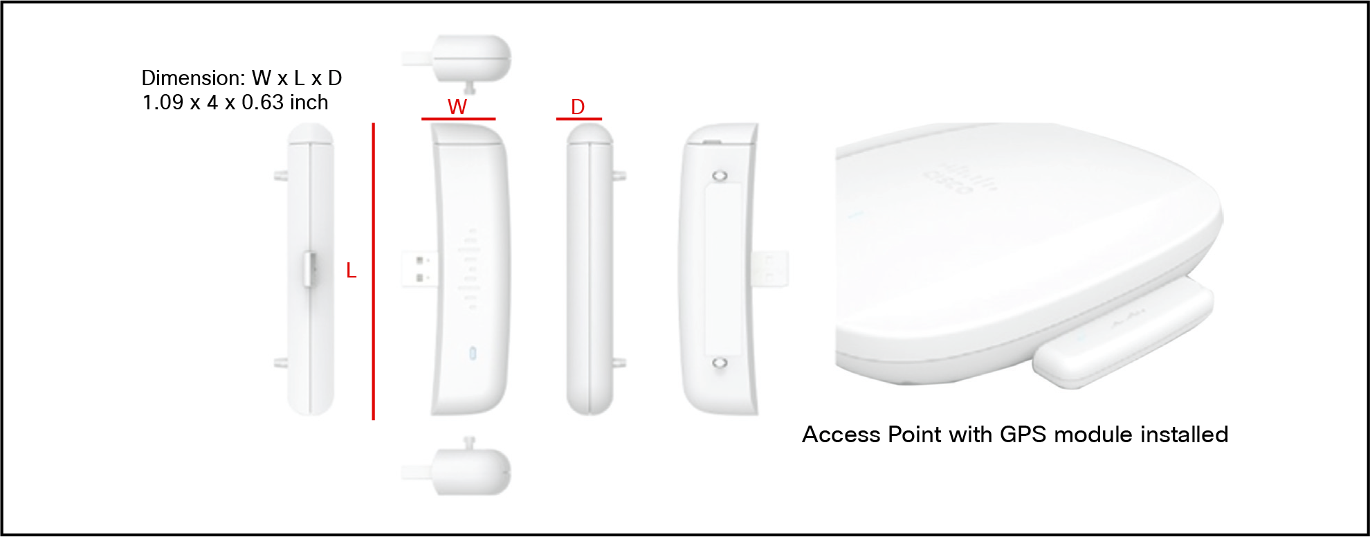
Figure 1.
GNSS module dimensions: 1.09 x 4 x 0.63 in. (2.77 x 10.16 x 1.6 cm)
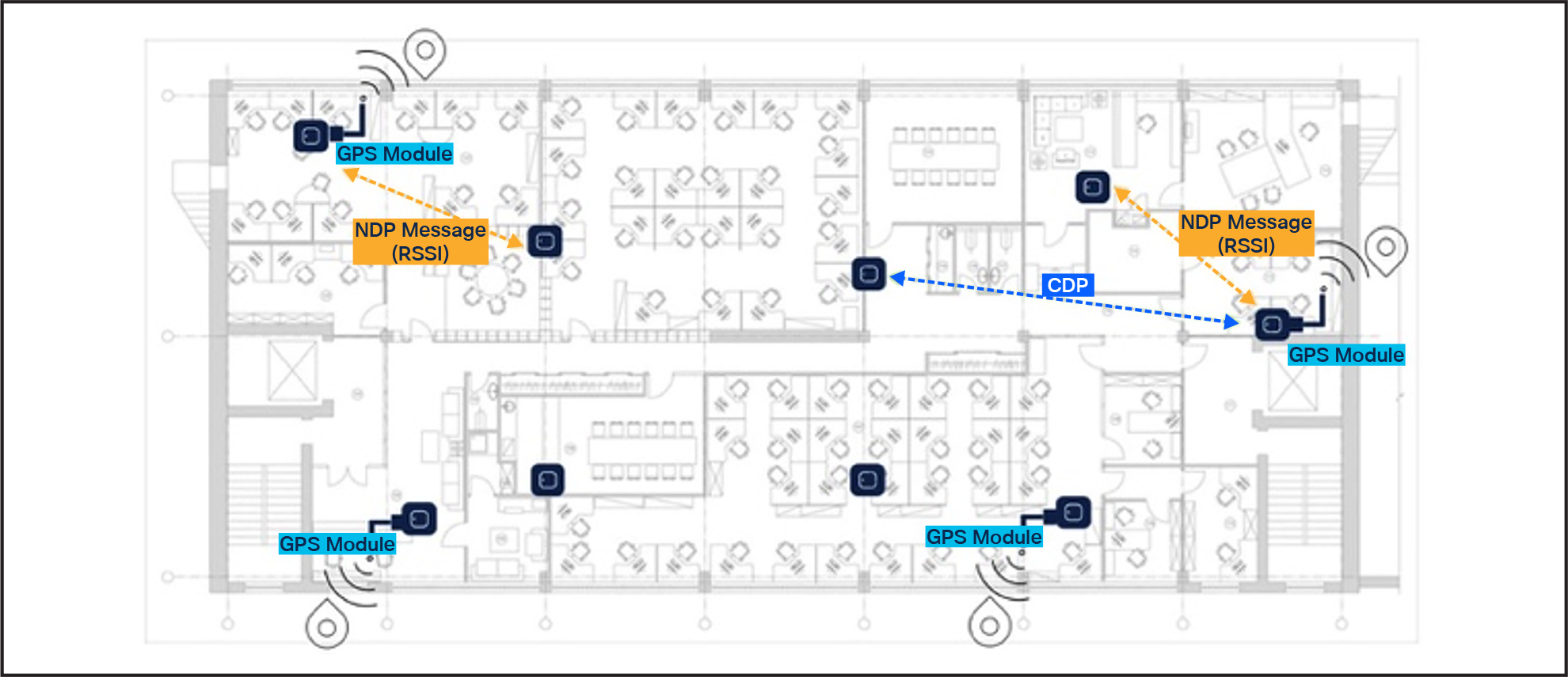
Figure 2.
Deployment of access points with GNSS modules at building corners
Note: In most cases, geolocation information derived through wireless techniques provides less uncertainty. The wireless controller automatically selects the best method to achieve the least uncertainty.
Q. How are the GNSS module and external antenna cable ordered?
GNSS module product ID: CW-ACC-GPS1=
External antenna product ID: CW-ANT-GPS2-S-00
Q. How is AFC performance monitored?
A. The overall health of the AFC service can be monitored via the Cisco Catalyst 9800 Series Wireless Controller using the WebUI under
monitoring/services/AFC and at the access point level under
monitoring/wireless/access point statistics/AFC statistics. The AFC response per access point is also available under the 360-degree view/AFC tab.
For cloud-managed deployments using the Meraki dashboard, the AFC response per access point is available under
Wireless/Monitor/Access points – select
AP/AFC.
Q. Which wireless controllers support AFC?
A. AFC is supported via Cisco Catalyst 9800 Series Wireless Controllers and the Meraki dashboard.
Q. Is AFC available via Cisco Catalyst Center?
A. Yes, Cisco Catalyst Center supports AFC to enable Standard Power 6 GHz operations through geolocation configuration in the AP workflow and supports monitoring via the AP 360 RF tab.
Version-Specific Documentation
● Release 2.3.7.x: Refer to the Catalyst Center 2.3.7 User Guide for configuring AP geolocation and the Assurance Guide for monitoring 6 GHz AFC status.
● Release 3.1.x: Refer to the Catalyst Center 3.1 Release Notes for updated support details on AFC-driven Standard Power operations in the AP 360 window.
Q. Where can information on configuring AFC be found?