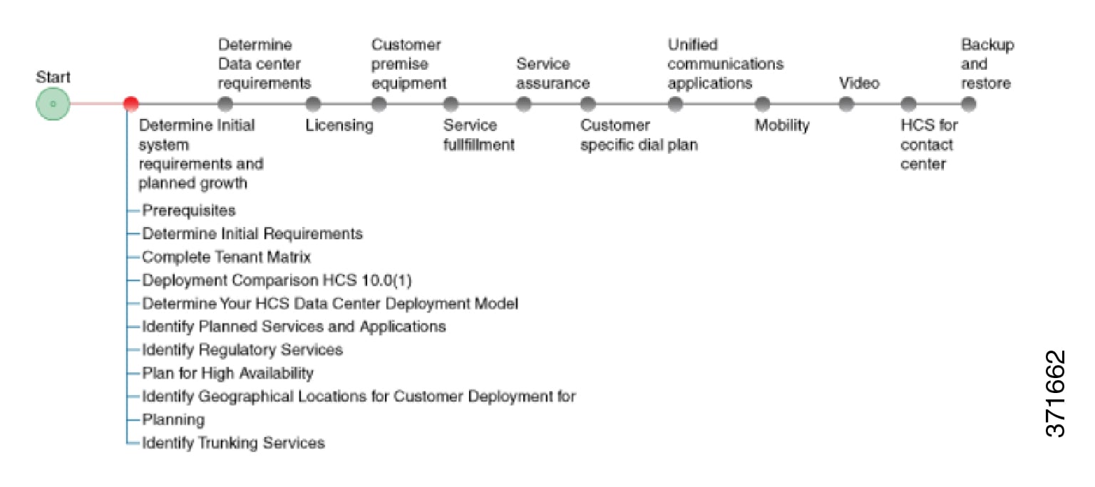
Initial System Requirements Planned Growth

Prerequisites

Before you plan the initial system requirements and the growth of Cisco Hosted Collaboration Solution (HCS), ensure you refer to the Collaboration Sizing Tool: http://cucst.cloudapps.cisco.com/landing.

You can review the following documents:

  • Cisco Hosted Collaboration Solution Solution Reference Network Design Guide

  • Cisco Hosted Collaboration Solution Capacity Planning Guide


Note

In Shared Architecture deployment, if you are planning to add more number of customers or sites, contact A2Q (hcbu-a2q@cisco.com).


Initial Requirements Workflow

Determine Initial Requirements

The following steps guide you through the critical pieces of planning your initial system requirements and growth. These steps help to frame the overall architecture and design of your system. Be sure to address the prerequisites for this section before proceeding.


Note

The Guided System Selling https://www-gsc.cisco.com/swc/cisco/ciscoAdvisor.action?sfId=CISCO&configSetAvailable=&scFlag=Y questionnaire can provide many of the details discussed. This section provides additional information for you to consider during planning. If you have information about your system from this questionnaire, use that information as part of your deployment planning process.

Procedure


Step 1

Complete Tenant Matrix

Step 2

Determine Your HCS Data Center Deployment Model

Note 
Make sure that you determine the expected latency for the Cisco Unified Communications Domain Manager to UC Application delay tolerance before planning your deployment.
Note 

Cisco HCM-F will deprecate the support of Cisco Unified Communications Domain Manager in the upcoming releases with limited support for existing integration, Cisco HCS partners and customers are advised to take necessary steps to align their requirements.

Step 3

Identify Planned Services and Applications

Step 4

Identify Regulatory Services

Step 5

Plan for High Availability

Step 6

Identify Geographical Locations for Customer Deployment for Planning

Step 7

Identify Trunking Services

Step 8

Plan for growth and the customer premise equipment site.

For more details, see Prerequisites


Complete Tenant Matrix

Collect information about the estimate size of your initial system and use the tenant matrix below to compute the average tenant size for a deployment, along with the total number of tenants.

Note

In the context of HCS, a Service Provider is a company that purchases or leases Cisco HCS equipment from Cisco. The Service Provider enlists customers on the same HCS system, and these customers are referred to as tenants and therefore, one Service Provider will, in general, have multiple tenants. Each tenant is a separate entity/company.

Procedure


Step 1

Determine Percent Distribution and Total Deployment size.

Step 2

Use the following tenant matrix to collect information about your planned system and to help develop your growth plans.

Number of End Users
Tenant Size
20 50 100 250 500 1,000 2,500 5,000 7,500 10,000 15,000 25,000 30,000 Totals
Percentage Distribution
Weighted Average
Number of Tenants
Step 3

Enter the following information into the tables above:

  • Number of End Users—Represents the total number of users expected for the HCS deployment across all tenants and customers.
  • Tenant Information—Either the Number of Tenants or the Percentage Distribution for each tenant size.
  • Weighted Average— Computed average tenant size using the different percentages (distribution) in the table above.
Step 4

Review the following results in the table:

  • Average tenant size
  • Total number of tenants—This number is important for computing limits that are related to the routing table and security contexts, among others.

The following examples can assist you with the construction of the table.

Tenant matrix - Example 1

To deploy a Cisco HCS system for which the exact number of tenants of each size is known, update the Number of Tenants row directly in the table, as shown in the following table:

Table 1. Details included after adding required information - Example 1
Tenant Size 20 50 100 250 500 1,000 2,500 5,000 7,500 10,000 15,000 25,000 Totals
Percentage Distribution
Weighted Average
Number of Tenants 0 10 40 20 100 5 3 1 0 0 0 0 179

The total number of tenants in this example is 179.

Because the number of tenants of each size is known, you can calculate the total deployment size (number of end users) as in the following equation:

 Number End Users = 10*50 + 40*100 + 20*250 + 100*500 + 5*1,000 + 3*2,500 + 1*5,000= 500 + 4,000 + 5,000 + 50,000 + 5,000 + 7,500 + 5,000 = 77,000

Therefore, the total number of end users is 77,000.

The percentage distribution represents the proportion of tenants of a particular size. It is defined as follows:

 Percentage Distribution_Size_N = Number Tenants_Size_N / Total_Number_of_Tenants

For example, Percentage Distribution_Size_50 = 10/179 = 5.6%

By computing the Percentage Distribution for each of the tenant sizes, you receive the following results:
Table 2. Percentage distribution - Example 1
Tenant Size 20 50 100 250 500 1,000 2,500 5,000 7,500 10,000 15,000 25,000 Totals
Percentage Distribution 0.0% 5.6% 11.2% 55.9% 2.8% 1.7% 0.6% 0.0% 0.0% 0.0% 0.0% 0.0% 100%
Weighted Average
Number of Tenants 0 10 40 20 100 5 3 1 0 0 0 0 179

The final step involves computing the Weighted Average. This value represents the contribution of each tenant size to the total number of end users. The Weighted Average is defined as:

Avg_Wt_Size_N = Percentage Distribution_Size_N * Tenant_Size

Note

Repeat this equation for each tenant size.
This value would be zero if there were not any tenants for that size. In this example, the Weighted Average for the following tenant sizes would be zero:
  • 20
  • 7,500
  • 10,000
  • 15,000
  • 25,000

The final table can now be calculated:

Table 3. Weighted Average - Example 1
Tenant Size 20 50 100 250 500 1,000 2,500 5,000 7,500 10,000 15,000 25,000 Totals
Percentage Distribution 0.0% 5.6% 11.2% 55.9% 2.8% 1.7% 0.6% 0.0% 0.0% 0.0% 0.0% 0.0% 100%
Weighted Average 0.0 2.8 22.3 27.9 279.3 27.9 41.9 27.9 0.0 0.0 0.0 0.0 430.2
Number of Tenants* 0.0 10 40 20 100 5 3 1 0.0 0.0 0.0 0.0 179
1

Deployment Comparison HCS

Review the following table to see a comparison of the different options available for each deployment model.

Table 4. Comparison—Data Center Infrastructure Models
Function or Product Large PoD Small PoD
Number of tenants*** Up to 940 Approximately 80
Note 
Storage switches such as Cisco MDS 9000 switches are optional and aren't required for Small PoD deployments.
Aggregation Nexus 7000, Nexus 9396, Nexus 9508 Nexus 5500
Cisco Unified Compute System (UCS) UCS with B-series blades UCS with B-series blades
Storage Fabric interconnect, SAN or NAS storage Fabric interconnect, SAN or NAS storage
Media/Signaling Anchoring Device (Multi-VRF-Enabled for Multiple customers)

Third-party SBC

Third-party SBC

Security ASA 5585-X ASA 5555-X
(Optional) Site-to-Site VPN Concentrator SBC SBC
(Optional) Line Side Access SBC SBC
(Optional) Shared Cisco Expressway for Business to Business Dialing with Non HCS Enterprises over Internet Expressway-C and Expressway-E on UCS B-series Expressway-C and Expressway-E on UCS B-series
(Optional) Cisco Expressway Expressway-C and Expressway-E on UCS B-series Expressway-C and Expressway-E on UCS B-series
(Optional) Dedicated Instance Yes Yes
(Optional) OTT Remote Access with Expressway Yes Yes
(Optional) Shared RMS with Expressway Yes Yes
(Optional) Jabber Guest Yes Yes
(Optional) Webex CCA Yes Yes
(Optional) Business to Business Video through Shared Expressway Yes Yes

Determine Your HCS Data Center Deployment Model

Review the detailed descriptions of each type of deployment in the Cisco Hosted Collaboration Solution Release 14 Solution Reference Network Design Guide and the Cisco Hosted Collaboration Solution Release 14 Capacity Planning Guide before proceeding. Your growth plans will help you determine the best solution for you.

Procedure


Step 1

Review decision-making factors for each of the following deployment models.

Note 
The details you gathered using the Guided System Selling tool should define which deployment model is right for you. The following details are for reference only.
  1. Large PoD

    The Large PoD deployment supports a large number of tenants and can also support incremental additions of compute and storage resources.

  2. Small PoD

    The Small PoD deployment also supports a significant number of tenants, although fewer than the large PoD. This deployment supports incremental additions of compute and storage resources, has only a moderate initial CAPEX and has a smaller data center footprint. If the tenant capacity is used faster than expected, you will need to add another instance of Small PoD. Over time the additional compute resource CAPEX required to expand a Micro Node deployment will exceed the CAPEX for an equivalent Small PoD deployment.

  3. Micro Node

    Micro Node supports a smaller number of tenants. This deployment supports the incremental addition of compute and has a low initial CAPEX. It also has a smaller data center footprint and supports migration to Small PoD. The addition of compute resources, however, eventually exceeds the CAPEX cost beyond a Small PoD deployment. Micro Node deployment does not support shared storage.

Note 
Cisco NX-OS Release 6.2 software requires 8 GB of memory. If you plan to use a Cisco Nexus 7000 Series system you will need to 8 GB of memory. This does not provide any additional performance or scale.

Based on the information that you have gathered and the parameters of each deployment model, you can determine which model is appropriate.

Step 2

Consider the following options site types for your deployment.

Note 
Site type decisions are made based on a per customer basis. Depending on your customer requirements, you can have one or more site types as part of your HCS.

For more detailed information on the different types of sites, see the Cisco Hosted Collaboration Solution Release 14 Solution Reference Network Design Guide

  1. Hosted

    Consider this option if you want all of the UC applications to reside in the HCS data center and endpoints located at one or more remote customer sites. This option is simplest to deploy and manage as all the call control and management servers are in the HCS data center.
  2. Remote managed

    Consider this option if you want all Unified Communications applications on premises, with Cisco HCS providing central breakout if necessary, and remote management through Hosted Collaboration Mediation-Fulfillment and Cisco Unified Communications Domain Manager. You will also need a deployment of Small PoD size data center at the remote site to host the UC applications.
  3. Hosted Private Cloud/Large Enterprise

    Consider this option if you need support for a very large customer with multiple clusters, potentially multiple independent organizational units, geographically and distributed operations. Examples include financial institutions or retailers with national coverage or Government organization. This Private Cloud deployment has its own HCS license type (HCS-LE) for UC and Management, which unlike MSP cannot be shared i.e. cannot resell or offer managed services. This one customer typically owns the hardware and manages the system. This deployment may optionally have its aggregation system.
Step 3

Identify OVA sizes to help with growth plans.

Important 

CPU oversubscription is only allowed for specific VMs where reservations are identified in the Cisco Hosted Collaboration Solution Compatibility Matrix. Otherwise, all VMs must map one VM vCPU core to one physical CPU core. The following are not supported in Cisco HCS:

  • Memory (RAM) oversubscription
  • Storage oversubscription
  • Storage thin provisioning (at VM layer or storage array layer)
  • Hyperthreading

Consider expected customer growth when selecting the initial OVA file for deploying UC Applications. For example, if you do not expect to experience much growth over the next six to 12 months, selecting an OVA that fits your initial deployment should be adequate. If, however, you expect to grow beyond the initial OVA size over the next six to 12 months, Cisco recommends you select a larger OVA to fit the expected growth level and not an OVA that fits your initial deployment level.

Initially, selecting a larger OVA for your deployment consumes more resources, however, the amount of time required to resize a virtual machine is significant. If you are unsure about your growth plans, however, you should evaluate whether the potential cost of allocating resources for a larger OVA is a suitable solution. A time-cost of downsizing also exists.


Small Medium Business Solutions

The classic Service Provider Service Provider Cisco HCS Data Center infrastructure model includes Nexus 7000 switches, SAN, UCS with B-series blade servers, a session border controller (SBC), and so on, that support a large number of end users across a high number of customers. This involves considerable initial cost and is suitable for large service providers.

For service providers with less than 940 tenants or shared clusters, there are a number of ways that you can deploy the data center infrastructure using smaller hardware components and shared application models to optimize scale and cost. You can deploy the Cisco HCS small/medium business solution on any of the data center infrastructure models.

Dedicated Instance

Dedicated instance refers to the model of applications where there is a separate application instance (Cisco Unified Communications Manager) for each customer. In one B or C-series server there can be different customer instances based on how applications are distributed in the server. Any reference to a UC application such as Cisco Unified Communications Manager, Cisco Unified Communications Manager IM and Presence Service, Cisco Unity Connection Cisco Emergency Responder, and CUAC, that does not include "Shared" or "Partitioned" as part of the title implies that it is a dedicated instance. Since the dedicated instance model is the same as in a large enterprise solution, no further description is provided here.

Partitioned Unity Connection

To help the Cisco HCS solution scale more customers on the same hardware, you can partition a single Cisco Unity Connection instance to support multiple customer domains.

Cisco Unity Connection exposes the configuration and provisioning to support multiple customers by REST APIs. The Cisco HCS service fulfillment layer uses the partitioned Unity Connection REST APIs to allow Cisco HCS service providers to configure and provision customers into the partitioned Unity Connection.

Cisco HCS continues to support the dedicated Cisco Unity Connection in addition to the new partitioned instance. Partitioned Unity Connection is not a new product with a new SKU. The HCS administrator and domain managers must decide the role of Unity Connection as either regular or partitioned.

The following deployment option is supported:

  • Use Cisco Unified Communications Domain Manager to provision partitioned Cisco Unity Connection if you are running version .

The current dedicated Cisco Unity Connection virtual machine (VM) uses an overlapping IP address. The same VM is used for partitioned Cisco Unity Connection with no change in the IP addressing. To provide access to multiple management devices such as Cisco Unified Communications Domain Manager and Prime Collaboration Assurance (which have global IP addresses) a hosted NAT device is required to perform address translations. You can leverage an existing NAT device that currently performs this function.

Because UC applications are not multi-VRF capable, Cisco Unified Communications Manager and partitioned Cisco Unity Connection cannot have a direct interface when Unity Connection is interfacing with multiple instances of Cisco Unified Communications Manager. In that case, third-party SBC is needed. However, it is possible to have a direct interface when only one instance of Cisco Unified Communications Manager is interfacing with Partitioned Unity Connection. The third-party SBC is required to perform this aggregation.

Identify Planned Services and Applications

Procedure


Review the Unified Communications applications and services to determine which you plan to use in your HCS deployment.

  1. Voice/Voicemail/IM

    • Cisco Unified Communications Manager

      Unified Communications Manager is supported across Large PoD, Small PoD, and Micro Node in a dedicated deployment.

      Cisco Unified Communications Manager is supported across Large PoD, Small PoD, and Micro Node in a deployment.

    • Cisco Unified Communications Manager IM and Presence Service

      Cisco Unified Communications Manager IM and Presence Service is supported across Large PoD, Small PoD, and Micro Node in a dedicated instance deployment.

    • Cisco Unity Connection

      Cisco Unity Connection is supported across Large PoD, Small PoD, and Micro Node in a dedicated deployment.

      Cisco Unity Connection is supported across Large PoD, Small PoD, and Micro Node in a deployment.

  2. Paging services

  3. Attendant Console (CUAC) (Server and serverless)

  4. Cisco Emergency Responder

  5. Video

    For more information on video planning, see Prerequisites.
  6. Mobility

    For more information on mobility planning, see Prerequisites

Identify Regulatory Services

Procedure


Step 1

Determine whether you need to provide Lawful Intercept (LI) services. Verify the LI requirement for the country in which you want to deploy to determine which services you must provide.

Step 2

Determine whether you need to provide emergency services. Verify the emergency services requirements for the country in which you want to deploy to determine which services you must provide.


Plan for High Availability

When planning for high availability in a Cisco HCS deployment, complete the following Cisco HCS-specific planning steps:

Infrastructure Redundancy (Steps 1-4)

Procedure


Step 1

Determine single versus multiple and geographic redundancy for data center deployments. Cisco recommends Layer 3 Geo-redundancy for HCS, deploying two data centers without SAN mirroring.

If you use Layer 2 Geo-redundancy instead of clustering over the WAN, you will need to determine whether to deploy the two data centers as active-active (which requires LAN and SAN extension) or active-standby (which requires only SAN extension). This in turn will determine your DC interconnect requirements; active-standby required SAN extension, whereas active-active requires both LAN and SAN extension.
Step 2

Determine available VMware redundancy and HA options, such as VMware HA and VMware vMotion.

Step 3

Determine blade and chassis redundancy, including spares and distribution of VM.

Step 4

Determine data center redundancy, data center core, aggregation, access layer, data center UCS platform and data center SAN storage:

  • Redundant Platforms (power, cards)
  • Redundant Layers: box, box redundancy
  • Redundant Fiber Channel storage
  • Redundant connections and paths
  • Virtualization VM tool set

Application Redundancy (Step 5)

Step 5

Plan for application redundancy, including failover redundancy and redundant links; again, Cisco recommends Layer 3 connectivity between UC applications. You will need to determine the desired round trip time delay for each application.

Note 

Application redundancy applies to all UC applications as well as Cisco HCS Provisioning, Assurance, and Domain Management applications. If applications are deployed within a single data center, we recommend that you deploy the virtualized applications on a different Unified Communications chassis if possible or at least upon different VMware ESXi hosts (server blades).

See the Cisco Hosted Collaboration Solution Release 14 Solution Reference Network Design Guide for more information and clustering recommendations for Cisco Unified Communications Manager, Cisco Unity Connection, and HCS for Contact Center.


Identify Geographical Locations for Customer Deployment for Planning

Procedure


Identify geographical locations planning considerations for customer deployment. Consider the number of different locations you plan to have as this can impact your initial deployment as well as your options for further growth. In particular, the number of locations, for example can affect the sizing of your Cisco HCM-F. You should also consider distance between various locations as this could affect network latency or potential delay issues.


Identify Trunking Services

Procedure


Depending on what type of provider you are, determine which trunking services to provide, either central, local breakout or a combination of both. For more details on these trunking choices, see Cisco Hosted Collaboration Solution Release 14 Solution Reference Network Design Guide.

  • Central Breakout

    Choosing central breakout may include obligations such as providing a carrier license, ability to provide emergency services, especially in situations where local breakout is not offered, and enabling Lawful Intercept (LI).

    With central breakout, you can use existing carrier grade SBC. For Large Enterprise deployments, use third-party SBC.

    You also have a choice of using Cisco Integrated Services Router G2 Series offering SRST or BRI, PSTN, and SIP trunking services.

  • Local Breakout

    Local breakout is a simple setup, that allows you to rely on another organization to provide the regulatory services for you. Local breakout may be a good alternative if you do not:

    1. Want the expense of investing in centralized aggregation infrastructure such as session border controllers.
    2. Want the additional burden of complying with and offering regulatory services.
    3. Have the license or operating in jurisdictions that do not allow certain organizations to offer central interconnect services, such as SIP or SS7.

1 * Tota; Number of Users = Total Deployment Size. Therefore, (430.2) * (179) = 77,005.8. Previously, we had indicated that our Deployment Size was 77,000. The difference between this number and the one calculated from the table is because of rounding.