IPsec with Network Isolation Utility

IPsec

Internet Protocol Security (IPsec) is a security standard developed jointly by Microsoft, Cisco, and many other Internet Engineering Task Force (IETF) contributors. It provides integrity (authentication) and encryption between any two nodes, which could be endpoints or gateways. IPsec is application independent because it works at layer 3 of the network. IPsec is useful for large and distributed applications like Unified ICM because it provides security between the application nodes independent of the application.

For more information, see https://docs.microsoft.com/en-us/windows/desktop/fwp/ipsec-configuration.

Manual Deployment or Network Isolation Utility

The Network Isolation Utility automates much of the work to secure a Unified ICM/Unified CCE environment using IPsec. The Network Isolation utility deploys a preconfigured IPsec policy that secures the entire network traffic to or from the Unified ICM/Unified CCE servers. Network connectivity is restricted to only those servers that share the same policy or are explicitly listed as exceptions.

If you wish to secure network traffic only between selected communication paths, do not use the Network Isolation Utility.

Cisco Network Isolation Utility

The Cisco Network Isolation Utility uses the Windows IPsec feature to isolate Unified ICM devices from the rest of the network. Examples of Unified ICM devices include the router, the logger, and the peripheral gateway device. The utility creates a Network Isolation IPsec policy, which sets Unified ICM devices as Trusted, and then authenticates and optionally encrypts all traffic between Trusted Devices. Traffic between Trusted Devices continues to flow normally without any additional configuration. All traffic to or from devices outside the Trusted Devices is denied unless it is classified as coming from or going to a Boundary Device.

A Boundary Device is a device without an IPsec policy that is allowed access to a Trusted Device. These devices typically include the Domain Controller, the Unified CM, default gateway devices, serviceability devices, and remote-access computers.

Each Trusted Device has its own list of Boundary Devices. Separate IP addresses or subnets or ports define the Boundary Devices.

The Network Isolation policy uses the IPsec ESP (Encapsulating Security Payload) protocol for integrity and encryption. The cipher suite deployed is as follows:

  • IP Traffic Security:

    • Integrity algorithm: SHA1

    • Encryption algorithm: 3DES

  • Key Exchange Security:

    • Integrity algorithm: SHA1

    • Encryption algorithm: 3DES (optional)

    • Diffie-Hellman group: High (2048-bit key)

Network Isolation Utility Information

The following sections discuss the Network Isolation Utility design and how it works.

IPsec Terminology

The following list contains definitions of basic IPsec terminology:

Policy

An IPsec policy is a collection of one or more rules that determine IPsec behavior. In Windows Server multiple policies can be created but only one policy can be assigned (active) at a time.

Rules

Each rule is made up of a FilterList, FilterAction, Authentication Method, TunnelSetting, and ConnectionType.

Filter List

A filter list is a set of filters that match IP packets based on source and destination IP address, protocol, and port.

Filter Action

A filter action, identified by a Filter List, defines the security requirements for the data transmission.

Authentication Method

An authentication method defines the requirements for how identities are verified in communications to which the associated rule applies.

For fuller descriptions of Microsoft Windows IPsec terminology, see

https://docs.microsoft.com/en-us/windows/desktop/fwp/ipsec-configuration.

Network Isolation Utility Process

Run the Network Isolation Utility separately on each Trusted Device. Do not run the utility on Boundary Devices.

To allow traffic to or from Boundary Devices, manually configure the Boundary Devices list on each Trusted Device.

After you deploy the Network Isolation IPsec policy on a device, that device is set as Trusted. Traffic flows freely between it and any other Trusted Device without any additional configuration.

When you run the Network Isolation Utility, it does the following:

  1. Removes any IPsec policies that are already on that computer. This removal avoids conflicts so the new policy matches on all Unified ICM devices for a successful deployment.

  2. Creates a Cisco Unified Contact Center (Network Isolation) IPsec policy in the Windows IPsec policy store.

  3. Creates the following two rules for the policy:

    1. Trusted Devices Rule

      This rule involves the following items:

      • Trusted Devices Filter List: All traffic. One filter that matches all traffic.

      • Trusted Devices Filter Action: Require security. Authenticate using the integrity algorithm SHA1 and optionally encrypt using encryption algorithm 3DES.

      • Authentication Method: The authentication method used to create trust between computers is a Preshared Key.

        The Preshared Key can be a string of words, numbers, or characters except the double quote symbol. The minimum length for this key is 36 characters.

    2. Boundary Devices Rule

      This rule involves the following items:

      • Boundary Devices Filter List: (empty by default)

      • Boundary Devices Filter Action: Permit traffic without IPsec policy. Boundary Devices do not require IPsec to communicate with Trusted Devices.

  4. The Network Isolation Utility stores a copy of the Cisco Unified Contact Center IPsec policy in an XML file located in Network Isolation utility folder:<system drive>:\CiscoUtils\NetworkIsolation\CiscoICMIPsecConfig.XML.

    The XML files stores the policy state and the Boundary Device list. It does not store the preshared key.

  5. The Network Isolation Utility logs all commands and actions in a log file at: <SystemDrive>:\CiscoUtils\NetworkIsolation\Logs\CiscoICMNetworkIsolation.log.

    The utility keeps one copy of the log file and appends all commands and actions to any previously created logs.

Traffic Encryption and Network Isolation Policies

The Network Isolation policy allows only those computers that have the same preshared key to interact. With Network Isolation, an outside hacker cannot access a trusted computer. But, without encryption enabled, a hacker can still see the traffic coming and going from that computer. Therefore, consider encrypting that traffic.


Note


  • You cannot encrypt traffic to one Trusted Device alone. Encrypt traffic on either all Trusted Devices or none. If only one computer has encrypted traffic, then none of the other Trusted Devices understand it.
  • Use encryption offload NICs when IPsec is enabled with encryption so that the encryption software does not affect performance.

Network Isolation Feature Deployment

The following sections discuss issues to be aware of when designing your deployment plan.

Important Deployment Tips

No configuration is needed on Boundary Devices. All the configuration is done on Trusted Devices. The Network Isolation Utility configures Trusted Devices to interact with other Trusted Devices and with Boundary Devices. The network isolation feature is applied on one device at a time. This feature instantly limits communication with other devices after it is applied. So, carefully plan how to deploy this feature before using it or you could accidentally stop your network from working. Write a deployment plan before you implement the Network Isolation feature. Deploy this feature therefore only during a maintenance window and review the caveats before writing your deployment plan.

Sample Deployment

The following is one sample deployment.

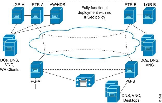
  1. Start with a fully functional Unified ICM or Unified CCE system that has no IPsec policy deployment.

    Figure 1. Example Unified Contact Center System


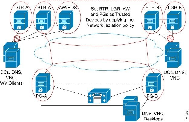
  2. Set the CallRouter, the Logger, the Administration & Data Server, and the PGs as Trusted Devices by running the Network Isolation Utility on each of them.

    Figure 2. Example: Add Trusted Devices


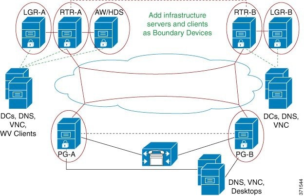
  3. Add the infrastructure servers and clients as Boundary Devices.

    Figure 3. Example: Add Boundary Devices


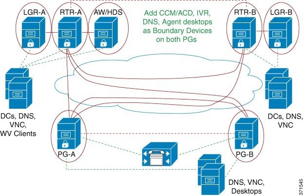
  4. Add Unified Communications Manager or ACD server, the DNS, and the agent desktops as Boundary Devices on both PGs.

    Figure 4. Example: Add Boundary Devices on PGs


    When you are finished, all Unified Contact Center Trusted Devices communicate only with each other and their respective Boundary Devices (the domain controller, the DNS, the Unified Communications Manager, and so on). Any network attack from outside cannot reach the Trusted Devices, unless it is routed through the Boundary Devices.

Device Two-Way Communication

This table lists the two-way communications requirements in a Unified CCE deployment. You can set the target devices as either Trusted or Boundary Devices.

Unified CCE component

Target Devices

CallRouter

CallRouter (on the other side in a redundant system)

Logger

Administration & Data Server/Historical Database Server

NAM Router

Peripheral Gateway (on both sides in a redundant system)

Application Gateway

Database Server

Network Gateway

Logger

Historical Database Server/Administration & Data Server

CallRouter

Campaign Manager

Dialer

Peripheral Gateway

Multichannel/Multimedia Server

CallRouter (on both sides in a redundant system)

Peripheral Gateway (on the other side in a redundant system)

Unified Communications Manager

Administration & Data Server legacy PIMS/switches

Administration & Data Server/Historical Database Server

Multichannel/Multimedia Server

Router

Logger

Custom Application Server

CON API Clients

Internet Script Editor Clients/Webskilling

Third-Party Clients/SQL party

Administration Server, Real-time and Historical Data Server, and Detail Data Server (AW-HDS-DDS)

Multichannel/Multimedia Server

Router

Logger

Custom Application Server

Internet Script Editor Clients/Webskilling

Third-Party Clients/SOL party

Boundary Devices and Unified CCE

This table lists the Boundary Devices That are typically required in a Unified CCE deployment:

Boundary Device

Configuration Example

Domain Controllers: such as those for RTR, LGR, Administration & Data Server or HDS, and PGs

  • Boundary Device: Domain Controller IP Address

  • Traffic Direction: Outbound

  • Protocol: Any

  • Port: Not Applicable

DNS, WINS, Default Gateway

—

Remote Access or Remote Management software: such as that for every Trusted Device (VNC, pcAnywhere, Remote Desktop Connection, SNMP)

VNC:

  • Boundary Device: Any host

  • Traffic Direction: Inbound

  • Protocol: TCP

  • Port: 5900

Unified Communications Manager Cluster for PGs

  • Boundary Device: A specific IP Address (or Subnet)

  • Traffic Direction: Outbound

  • Protocol: TCP

  • Port: All ports

Agent Desktops

Finesse Server:

  • Boundary Device: A Subnet

  • Traffic Direction: Inbound

  • Protocol: TCP

  • Port: 42028

Caveats

Carefully plan deployments so that the policy is applied to all machines at the same time. Otherwise, you can accidentally isolate a device.

Caveats include the following:


  • Important


    Enabling the policy remotely blocks remote access unless a provision is made in the Boundary Device list for remote access. Add a Boundary Device for remote access before enabling the policy remotely.


  • Important


    Add all domain controllers as Boundary Devices or your domain login fails. If domain login fails, your Unified ICM services also fail to start or you can see delayed login times. This list of domain controllers includes all domains in which Unified ICM is installed. The list also includes all domains in which Web Setup tool, configuration users, and supervisors exist.


  • Adding a new device as a Boundary Device requires a change to the policy on all Trusted Devices that need access to this new device without IPsec.

  • A change in the Preshared Key must be invoked on all Trusted Devices.

  • If you enable encryption on only one Trusted Device, that device cannot communicate with the other Trusted Devices because its network traffic is encrypted. Enable encryption on all or none of the Trusted Devices.

  • Do not use the Windows IPsec policy MMC plug-in to change the IPsec policy. The Network Isolation Utility maintains its own copy of the policy. Whenever the Network Isolation Utility executes, the utility reverts to its last saved configuration, ignoring any changes made outside the utility (or the Security Wizard).

  • The Network Isolation Utility does not interfere with applications that run on the network. However, run the utility only during the application maintenance window because the utility can disrupt connectivity when you set up the network security.

  • If your network is behind a firewall, then configure the firewall to:

    • Allow IP protocol number 50, which is the ESP (Encapsulating Security Protocol).

    • Allow UDP source and destination traffic on port 500 for the IKE protocol.

  • If you are using the NAT protocol, configure the firewall to forward traffic on UDP source and destination port 4500 for UDP-ESP encapsulation.

  • Any changes made to the application port usage, such as a web server port, must also be reflected in the policy.

  • Deploy the Network Isolation Policy after the Unified ICM or the Unified Contact Center application is configured and confirmed to be working.

  • For an inventory of the ports used across the contact center suite of applications, see the following documentation:

    To aid in firewall configuration, these guides list the protocols and ports used for agent desktop-to-server communication, application administration, and reporting. They also provide a listing of the ports used for intra-server communication.

Batch Deployment

You can use the following XML file to help speed up deployment when a common set of Boundary Devices must be added to all Trusted Devices:

<system drive>:\CiscoUtils\NetworkIsolation\CiscoICMIPsecConfig.XML

This XML file contains the list of Boundary Devices and policy state for one Trusted Device. You can use this file to replicate the policy on other Trusted Devices.

For example, when setting up your PGs as Trusted Devices, you can first complete configuring one Unified ICM PG. Next, you can copy the XML file from that PG to the rest of your Unified ICM PGs. Then, run the Isolation Utility (or the Security Wizard) on the other PGs to replicate the same Boundary Device list on all your PGs.

Network Isolation Utility Command-Line Syntax

You can run the Network Isolation Utility either from the command line or from the Unified Contact Center Security Wizard.


Note


Use the Security Wizard for initial policy creation or modification. You can use the command line for batch deployment.

To run the utility from the command line, go to the C:\CiscoUtils\NetworkIsolation directory, where the utility is located, and run it from there:

C:\CiscoUtils\NetworkIsolation>

The following is the command-line syntax for enabling the policy on Trusted Devices:

cscript ICMNetworkIsolation.vbe <arguments>

Note


You must use cscript to invoke the script.

You can add Boundary Devices with multiple filters. You can filter them by:

  • IP Address: Individual IP addresses or by an entire subnet of devices

  • Dynamically detected devices: DNS, WINS, DHCP, Default Gateway

    Windows dynamically detects the IP address of these devices and keeps the filter list updated

  • Direction of traffic: Inbound or outbound

  • Protocol: TCP, UDP, ICMP, or any protocol

  • Port (only if TCP or UDP is selected): A specific port or all ports

In the syntax:

  • angle brackets < >= required

  • square brackets [ ] = optional

  • pipe or bar | = any one of the items between the bars

The following table lists the command syntax for all uses of the command.

Table 1. Network Isolation Utility Command Syntax for Each Argument

Argument Name

Syntax and Example

Function

HELP

cscript ICMNetworkIsolation.vbe /?

Displays the syntax for the command.

ENABLE POLICY

cscript ICMNetworkIsolation.vbe /enablePolicy <36+ characters PreSharedKey in double quotes> [/encrypt]

Note


The only nonsupported character for use in the PresharedKey is double quotes because that character marks the beginning and end of the key. You can enter any other character within the key.

For example:

cscript ICMNetworkIsolation.vbe /enablePolicy "myspecialpresharedkey123456789mnbvcx"

Creates a new policy or enables an existing one from the stored policy XML file.

Optionally enables encryption of the network traffic data.

Creates a new policy in Windows IPsec policy store and adds all Boundary Devices listed in the XML file. If the XML file does not exist, then it creates a new XML file. The /encrypt option overrides the value set in the XML file.

Note

 
The add, remove, and delete arguments make a backup of the XML file and name it xml.lastconfig before carrying out their function.

ADD BOUNDARY

cscript ICMNetworkIsolation.vbe /addBoundary DNS|WINS|DHCP|GATEWAY

For example:

cscript ICMNetworkIsolation.vbe /addBoundary DNS

This example adds the DNS server to the Boundary Device list.

Adds to the Boundary Device list the type of device specified.

The type can be specified as DNS, WINS, DHCP, or GATEWAY.

The utility recognizes DNS, WINS, DHCP, and GATEWAY as the Domain Name System (DNS) device, the Windows Internet Name Service (WINS) device, the Dynamic Host Configuration Protocol (DHCP) device, and the default Gateway (GATEWAY) device respectively.

The Windows operating system dynamically detects a change in IP address for each of the preceding types of devices and dynamically updates the Boundary filter list accordingly.

cscript ICMNetworkIsolation.vbe /addAnyHostBoundary <Outbound|Inbound> <TCP|UDP> <PortNumber>

For example:

cscript ICMNetworkIsolation.vbe /addAnyHostBoundary Inbound TCP 5900

This example allows VNC access from all machines.

Adds to the Boundary Device list any device that matches the following criteria:

  • One of the specified traffic directions (outbound or inbound).

  • One of the specified protocols, Transmission Control Protocol (TCP) or User Datagram Protocol (UDP).

  • The specified port.

cscript ICMNetworkIsolation.vbe /addIPAddrBoundary <IP address> <Outbound|Inbound> <TCP|UDP|ICMP|Any> [All|PortNumber]

For example:

cscript ICMNetworkIsolation.vbe /addIPAddrBoundary 10.86.121.160 Outbound Any

This example allows all outbound traffic to a device with the specified IP address.

Adds to the Boundary Device list the IP address of a device that has the following configuration:

  • (required) The specified IP address.

  • (required) One of the specified traffic directions (outbound or inbound).

  • (required) One of the specified protocols (required): Transmission Control Protocol (TCP), User Datagram Protocol (UDP), Internet Control Message Protocol (ICMP), or any protocol.

  • (optional) any port or a specified port if the selected protocol is TCP or UDP.

cscript ICMNetworkIsolation.vbe /addSubnetBoundary <StartingIP address> <Subnet Mask> <Outbound|Inbound> <TCP|UDP|ICMP|Any> [All|PortNumber]

Adds to the Boundary Device list the subnet that has the following configuration:

  • (required) The starting IP address of the following specified range.

  • (required) The specified subnet mask (a range of logical addresses within an address space).

  • (required) One of the specified traffic directions (outbound or inbound).

  • (required) One of the specified protocols, Transmission Control Protocol (TCP), User Datagram Protocol (UDP), Internet Control Message Protocol (ICMP), or any protocol.

  • (optional) any port or a specified port if TCP or UDP is selected as the protocol.

REMOVE BOUNDARY

cscript ICMNetworkIsolation.vbe /removeBoundary DNS|WINS|DHCP|GATEWAY

For example:

cscript ICMNetworkIsolation.vbe /removeBoundary GATEWAY

Removes from the Boundary Device list the type of device specified.

The type can be specified as DNS, WINS, DHCP, or GATEWAY.

The utility recognizes DNS, WINS, DHCP, and GATEWAY as the Domain Name System (DNS) device, the Windows Internet Name Service (WINS) device, the Dynamic Host Configuration Protocol (DHCP) device, and the default Gateway (GATEWAY) device respectively.

Windows dynamically detects a change in IP address for each of the preceding types of devices and dynamically updates the Boundary filter list accordingly.

cscript ICMNetworkIsolation.vbe /removeAnyHostBoundary <Outbound|Inbound> <TCP|UDP> <PortNumber>

For example:

cscript ICMNetworkIsolation.vbe /removeAnyHostBoundary Inbound TCP 5900

Removes from the Boundary Device list any host device at the specified IP address that matches the following criteria:

  • One of the specified traffic directions (outbound or inbound).

  • One of the specified protocols (TCP or UDP).

  • The specified port number for internet traffic.

cscript ICMNetworkIsolation.vbe /removeIPAddrBoundary <IP address> <Outbound|Inbound> <TCP|UDP|ICMP|Any> [All|PortNumber]

For example:

cscript ICMNetworkIsolation.vbe /removeIPAddrBoundary 10.86.121.160 Outbound Any

Removes from the Boundary Device list the device at the specified IP address that has the following configuration:

  • (required) The specified IP address.

    (required) One of the specified traffic directions (outbound or inbound).

  • (required) One of the specified protocols (TCP, UDP, ICMP, or any protocol).

  • (optional) any port or a specified port if TCP or UDP is the specified protocol.

cscript ICMNetworkIsolation.vbe /removeSubnetBoundary <StartingIP address> <Subnet Mask> <Outbound|Inbound> <TCP|UDP|ICMP|Any> [All|PortNumber]

For example:

cscript ICMNetworkIsolation.vbe /removeSubnetBoundary 10.86.0.0.255.255.0.0 Inbound Any

Removes from the Boundary Device list all the devices at the specified IP address that have the following configuration:

  • (required) The starting IP address of the following specified range.

  • (required) The specified subnet mask.

  • (required) One of the specified traffic directions (outbound or inbound).

  • (required) One of the specified protocols (TCP, UDP, ICMP, or any protocol).

  • (optional) a port or a specified port.

DISABLE POLICY

cscript ICMNetworkIsolation.vbe /disablePolicy

Disables the Unified ICM Network Isolation IPsec policy on the computer. However, the policy is not deleted and it can be re-enabled.

This option is helpful when troubleshooting network problems.

If you have a network connectivity problem and you do not know the cause, disable the policy to help you clarify the source of your problem. If you are still having the problem with the policy disabled, then the policy is not the cause of your problem.

DELETE POLICY

cscript ICMNetworkIsolation.vbe /deletePolicy

Deletes the Unified ICM Network Isolation Security policy from the Windows IPsec policy store and renames the XML file to CiscoICMIPsecConfig.xml.lastconfig.

Troubleshoot Network Isolation IPsec Policy

Use the following steps to troubleshoot the Network Isolation IPsec policy:

Procedure


Step 1

Disable the policy and confirm whether the network problem you experienced still exists. Shutting down the policy might not be an option on a highly distributed system. So, it is important that the policy is deployed after the Unified ICM application is configured and tested.

Step 2

Check whether an IP address or port specified in the Boundary Device list was modified after the policy was deployed.

Step 3

Check whether a communication path is set as Trusted and Boundary. An overlap of both causes communication to fail.

Step 4

Confirm by looking in the <system drive>:\CiscoUtils\NetworkIsolation\CiscoICMIPsecConfig.XML file whether the required Boundary Devices are listed as Boundary Devices. Use the Security Wizard to check the Boundary Devices.

Step 5

Changes made to the IPsec policy directly from the Windows MMC console are not reflected in the utility (or in the Security Wizard). The Enable Policy option always overwrites the IPsec policy store with the configuration stored in the XML file.

Step 6

Check for any listed caveats.