- Preface
- Outbound Business Concepts
- Architectural Overview
- Outbound Option Installation: Preliminary Steps
- Outbound Option Installation: SIP Dialer
- Outbound Option Installation: SCCP Dialer
- Configuration of Campaigns and Imports
- Administrative and Supervisory Tasks
- Registry Settings
- Long Distance Digit Prefix Logic
- Dialer_Detail Table
- Termination_Call_Detail Table
- Schedule of Contacts Between Customers and Agents
- CTI OS Outbound Option ECC Variable Settings
- Index
- Installation task maps
- Unified CCE Outbound Option Configuration
- Configuration and scheduling of personal callback feature
- Unified CMr and Gateway Configuration
- Outbound Option Software Installation Steps
- Installation of Cisco CTI Controls
Outbound Option Installation: SCCP Dialer
 Note | The SCCP Dialer is deprecated for release 10.0 and will reach end-of-sale in an upcoming release. |
This chapter, intended for system administrators performing the initial installation of Outbound Option, describes how to set up and install the Outbound Option platform in an SCCP Dialer deployment.
This chapter groups installation activities to minimize switching between configuration and actual software installation. The general flow lists Unified CCE configuration first, then the Unified CM configuration, and then the Outbound Option component software installation and associated database creation.
Note | Cisco Finesse is not supported with the SCCP dialer. |
- Installation task maps
- Unified CCE Outbound Option Configuration
- Configuration and scheduling of personal callback feature
- Unified CMr and Gateway Configuration
- Outbound Option Software Installation Steps
- Installation of Cisco CTI Controls
- Setup of Outbound Option in Cisco Desktop Administrator
- Verification
Installation task maps
Unified CCE Outbound Configuration
The first phase of installing Outbound Option is configuring Unified CCE and Outbound Option components. The following table lists the steps that comprise Unified CCE Outbound configuration in the order that the steps should be performed, and provides pointers to where the tasks are discussed.
Step Number |
Task |
IPCC Enterprise Procedure |
System PG Procedure |
|---|---|---|---|
1 |
Configure the IPCC PG |
||
2 |
Configure the Dialer component |
||
3 |
Configure the port map |
||
4 |
Create a Network VRU |
||
5 |
Configure the Media Routing PG |
||
6 |
Configure a Skill Group |
||
7 |
Create a Dialed Number |
||
8 |
Create Translation Route To IVR |
IPCC Enterprise Documentation |
IPCC Enterprise Documentation |
9 |
Configure System Options |
||
10 |
Enable ECC Variables |
||
11 |
Configure and schedule personal callbacks (optional) |
Cisco Unified CM and Gateway Configuration
The following table lists the steps that comprise Unified CM configuration in the order that the steps should be performed, and provide pointers to where the tasks are discussed.
Software Installation and Database Creation
The third phase of installing Outbound Option is installing the component software and creating the associated database. The following table lists the steps that comprise software installation and database creation in the order that the steps should be performed and provides pointers to where the tasks are discussed.
Step Number |
Task |
IPCC Enterprise Procedure |
System PG Procedure |
|---|---|---|---|
1 |
Install the Outbound Option private database on the Logger Side A platform |
||
2 |
Install the Dialer component on the PG platform |
||
3 |
Edit Dialer-related Registry values |
||
4 |
Modify JTAPI for calls to invalid numbers |
||
5 |
Install the MR PG on the PG platform |
Unified CCE Outbound Option Configuration
This section provides procedures for the tasks associated with Unified CCE Outbound Option configuration.
- Configure IPCC PG
- Configure Dialer Component
- Configure Port Map
- Create a Network VRU
- Configure Media Routing PG (MR PG)
- Configure Skill Group
- Create Dialed Number
- Configure System Options
- Enable ECC Variables
Configure IPCC PG
Perform the following steps to configure the IPCC PG (PG1).
Configure Dialer Component
Perform the following steps to configure the Dialer component.
Configure Port Map
Perform the following steps to configure the port map for each Dialer. This specifies the number of ports available on the Dialer and the extension numbers, which Unified CM assigns to those ports. The maximum number of ports per SCCP Dialer is 120. Each configured port represents a Dialer phone device (Cisco 30 VIP) on Unified CM.
Extension numbers must be unique across the full enterprise. If there are multiple Unified CM clusters, the extensions (Unified CM directory number) must still be unique. Extension numbers can be up to ten digits in length.
When selecting extension numbers for Dialer ports, confirm that existing phone numbers in Unified CM and dial numbers in the Device Target Explorer tool are not already done.
| Step 1 | In the ICM Configuration Manager Outbound Option Dialer configuration window, click
the Port Map Selection tab to display the port map configuration.
| ||
| Step 2 | To begin adding ports to this Dialer, click Add. | ||
| Step 3 | Configure a set of ports and their associated extensions.
| ||
| Step 4 | Click OK. The port mappings appear on the Port Map Selection tab. | ||
| Step 5 | Click Save to save all the configuration information. | ||
| Step 6 | Click Export. The Select CM Version dialog appears. | ||
| Step 7 | Click the Unified CM option. (Select the latest Unified CM option if you are using a later version of Unified CM.) | ||
| Step 8 | Click OK and specify the path for the port mapping file. | ||
| Step 9 | Click Save to save the file. You will import this file, during Unified CM configuration. |
Create a Network VRU
Perform the following steps to create a Network VRU using the Network VRU Explorer tool.
| Step 1 | Open the ICM Configuration Manager application. |
| Step 2 | Open the Explorer tools. |
| Step 3 | Open the Network VRU Explorer tool. |
| Step 4 | Create a type 2 VRU to be used during Media Routing (MR) PIM setup. Record the \ VRU name: ______________. |
| Step 5 | Click Save. |
Note | See the ICM Configuration Guide for Cisco Unified ICM Enterprise for detailed information about the ICM Configuration Manager tools. |
Configure Media Routing PG (MR PG)
Perform the following steps to configure the MR PG (PG2).
| Step 1 | In ICM Configuration Manager, open the PG Explorer tool. |
| Step 2 | Click Retrieve, and then click Add. Add an MR PG. |
| Step 3 | Enter the name (for example, PG2_MR). |
| Step 4 | Select the MR PG type. |
| Step 5 | Add a peripheral. |
| Step 6 | Enter the name (for example, PG2_MR_PIM1). |
| Step 7 | On the Peripheral tab, check the Enable post routing check box. |
| Step 8 | On the Routing Client tab, enter the routing client name (for example, MR_PIM1_Voice). |
| Step 9 | Select the Cisco_Voice option from the Default media routing domain drop-down list. |
| Step 10 | On the Advanced tab, select the Network VRU that you created during system installation from the drop-down list. |
| Step 11 | Click Save. |
| Step 12 | Record the assigned Logical Controller ID for later use: ____________________. |
| Step 13 | Record the assigned Peripheral ID for later use: ____________________. |
Configure Skill Group
Perform the following steps to create a skill group for the PG using the Skill Group Explorer tool:
| Step 1 | In ICM Configuration Manager, open the Skill Group Explorer tool. |
| Step 2 | Confirm that the PIM created in the section Configure the PG is displayed in the Select filter data section. |
| Step 3 | Click Retrieve. |
| Step 4 | Click Add Skill Group. |
| Step 5 | Set the Media Routing Domain to the Cisco_Voice option. |
| Step 6 | Enter a peripheral name and number (record them):____________________. (You can either enter a name or allow the system to generate the name.) |
| Step 7 | Enable the ICM picks the agent check box. |
| Step 8 | Click Add Route. |
| Step 9 | Enter a name for the new route (any name is allowed). |
| Step 10 | Click Save. |
Create Dialed Number
Perform the following steps to create a dialed number for the MR PG.
| Step 1 | In ICM Configuration Manager, open the Dialed Number/Script Selector List tool. |
| Step 2 | Click Add, then enter a dialed number for the MR PG. |
| Step 3 | Select the MR routing client from the drop-down list. |
| Step 4 | Select Cisco_Voice from the Media Routing Domain drop-down list. |
| Step 5 | Enter the dialed number. |
| Step 6 | On the Dialed Number Mapping tab, click Add. |
| Step 7 | In the Calling Line ID group box, click the All radio button. |
| Step 8 | In the Caller-entered digits group box, click the All radio button. |
| Step 9 | In the Call type drop-down list, select the MR call type. |
| Step 10 | Click OK on the Dialed Number Map Entry dialog box, and then click Save. |
Note | To use the Personal Callback feature, a second dialed number is required. This dialed number must have the PersonalCallback dialed number string. As with the previous dialed number, map all Calling Line IDs and all Caller-entered digits to the call type previously created for the MR routing client. Multiple dialers require multiple dialed numbers—one for each routing client per skill group. |
Configure System Options
Use the Outbound Option System Options component in the ICM Configuration Manager to define contact dialing time ranges that apply to all of your Outbound Option campaigns.
Because this component uses 12-hour time notation, be sure to select AM or PM for your start and end times.
| Step 1 | In ICM Configuration Manager, open the Outbound Option System Options component. |
| Step 2 | Select the General Options tab page to define the total dialing time range for all your Outbound Option campaigns to use, and then click OK. |
| Step 3 | Select the Bulk Update tab page to define specific dialing time ranges for telephone numbers, and then click Update All Campaigns. |
Enable ECC Variables
Perform the following steps to enable the Expanded Call Context (ECC) variables using the System Information tool and the Expanded Call Variable List tool.
| Step 1 | Open the System Information tool in the Tools/Miscellaneous folder in the ICM Configuration Manager application. |
| Step 2 | Enable the Expanded call context enabled check box. |
| Step 3 | Click Save. |
| Step 4 | Open the List tools. |
| Step 5 | Open the Expanded Call Variable List tool. |
| Step 6 | Click all BAxxxx variables (BAAccountNumber, BABuddyName, BACampaign, BADialedListID, BAResponse, BAStatus, and BATimezone). |
| Step 7 | In the Attributes tab, click the Enabled check box for each variable. |
| Step 8 | Click Save. |
Configuration and scheduling of personal callback feature
Configure Personal Callbacks
Note | All personal callbacks occur in Preview mode. Be aware that only one Dialer on a particular peripheral is assigned personal callback records. |
Some personal callback options must be configured through the registry. Furthermore, if a personal callback record is not associated with a campaign, it follows the rules configured within the registry.
| Step 1 | Configure the reschedule callback mode in the Outbound Option Campaign Configuration Component by selecting one of the following options on the Campaign General tab: | |||||||||||||||||||||||||||||||||||||||||
| Step 2 | Open the HKEY_LOCAL_MACHINE\SOFTWARE\Cisco Systems, Inc.\ICM\<instance name>\LoggerA\BlendedAgent\CurrentVersion folder in the Outbound Option registry. | |||||||||||||||||||||||||||||||||||||||||
| Step 3 | Configure the personal callback registry entries listed in the following
table.
| |||||||||||||||||||||||||||||||||||||||||
| Step 4 | Set up the Personal Callback reservation script using the Script Editor
application.
For example, the following Personal Callback reservation script uses the nodes described above: This Image 271426.jpg is not available in preview/cisco.com |
Create Enterprise Skill Group
To use the Personal Callback feature, you need to create the enterprise skill group associated with the agent using the Enterprise Skill Group List tool.
| Step 1 | Open the List tools. |
| Step 2 | Open the Enterprise Skill Group List tool. |
| Step 3 | Create an enterprise skill group. In the Add Name field, type the enterprise name, then click Add. Select the skill group, and then click Save. |
| Step 4 | In the Attributes tab, click Add to add the skill group or groups. |
| Step 5 | Click Save. |
Create Enterprise Route
After you create the enterprise skill group associated with the agent, you need to create an enterprise route using the Enterprise Route List tool. This route should target the enterprise skill group created in the previous step.
Configure Queue to Agent Node
If you use personal callbacks, complete the following steps to configure the Queue to Agent Node in your reservation script.
| Step 1 | Right-click the Queue to Agent node and select Properties. |
| Step 2 | Click Change in the "Queue to agent type" section. |
| Step 3 | Select Lookup agent reference by expression, and then click OK. |
| Step 4 | Enter the agent expression Call.PreferredAgentID. |
| Step 5 | Select the enterprise skill group you created in the Creating an Enterprise Skill Group section. |
| Step 6 | Select the enterprise route you created in the Creating an Enterprise Route section. |
| Step 7 | Confirm that the Peripheral column is left blank. |
| Step 8 | Click OK to save the Queue to Agent node. |
| Step 9 | Save and then schedule the script. This Image 82971.jpg is not available in preview/cisco.com |
Unified CMr and Gateway Configuration
This section provides procedures for the tasks associated with the Unified CM and gateway configuration.
Ensure that each dialer’s ports are contained on their own UCManager subscriber, and the UCManager subscriber is not shared with any other Dialer. Because a Dialer port makes shorter calls at sustained higher call rates, it takes a larger portion of UCManager resources than a normal agent phone. The sizing calculator should have already been used to properly size when designing the solution. The port throttle configuration referenced in Dialer configuration prevents the Dialer from over-using its subscriber. If more than one Dialer points to the same subscriber, then this Dialer throttling mechanism is not effective because it only applies to each Dialer.
- Import and Assign Dialer Ports
- Disable Ringback During Transfer to Agent for SIP
- Auto Answer Configuration on Agent Phones
Import and Assign Dialer Ports
Perform the following procedure to import Dialer Ports and assign them to the PG’s CTI Application User.
| Step 1 | After configuring the Dialer Port Map, click
Select All, and then click
Export to save the port map configuration to a CSV-formatted
text file. Select the
Unified CM version.
| ||
| Step 2 | Use the Cisco Unified CM BAT tool to create a new phone template.
| ||
| Step 3 | Select . Click Add New. Browse to the CSV file, select Phones, select , and then click Save. | ||
| Step 4 | Select
. Select the file name and the phone template
name, click
Run Immediately, and then click
Submit.
To see the status of this job, select , and then click the Find button. | ||
| Step 5 | Associate the newly created devices with a PG user. In the Unified CM Administration window, select , and then click Find. | ||
| Step 6 | Select the Device Association link. In the Device List Filter, select the Directory Number and then enter the first few digits of the newly created Dialer ports. | ||
| Step 7 | Click Select Devices. Make sure the check box next to each Dialer port is checked. | ||
| Step 8 | Click Save. |
Disable Ringback During Transfer to Agent for SIP
The configuration for the SCCP Dialer does not work for the SIP Dialer. When the SIP Dialer is handing off the call to an agent, it sends REFER to the voice gateway. The voice gateway initiates a new SIP call (new INVITE) to CUCM, and then receives a 180 RINGING response. As a result, the gateway generates a ringback tone to the customer. With CUCM 8.5 and later, you can disable the ringback by applying a SIP normalization script to the CUCM SIP trunk. This script manipulates the 180 ringing to a 183 SESSION PROGRESS message to prevent the gateway from generating a ringback.
Note | Apply this script only to the SIP trunk that is handling the inbound call from voice gateway for agent transfer. If you use the same gateway for both PSTN calls and the SIP Dialer, you must configure separate trunks in CUCM and apply this normalization script only to the Dialer SIP trunk. The trunk for PSTN calls still needs a 180 ringing response for inbound calls to trigger the gateway to play ringback to the PSTN. |
Note | Skip step 1 if a dedicated SIP trunk already exists for handling agent transfer dial. Perform step 1 if the same SIP trunk is used for normal inbound PSTN calls and Dialer agent transfer calls. |
| Step 1 | To create a SIP trunk in CUCM with a SIP security profile for the Dialer agent transfer calls, select Communications Manager GUI > System > Security >SIP Trunk Security Profile>[Add New]. |
| Step 2 | Click Save. |
| Step 3 | Create a new IP trunk and associate the created SIP trunk Security Profile. |
| Step 4 | Click Save. |
| Step 5 | Click Reset. |
| Step 6 | In Communications Manager GUI > Device Settings > SIP Normalization Scripts [Create New], enter the following SIP normalization script into the content field. All other values remain set to default.
M = {}function M.outbound_180_INVITE(msg) msg:setResponseCode(183, "Session in Progress") endreturn M |
| Step 7 | Click Save. |
| Step 8 | Click Reset. |
| Step 9 | Associate the created normalization script with the SIP trunk. |
| Step 10 | Click Save. |
| Step 11 | Click Reset. |
Auto Answer Configuration on Agent Phones
The dialer component is preconfigured during installation to auto answer Outbound Option related calls to the Outbound Option agent. However, this default configuration does not provide a zip tone to the agent (which notifies of incoming calls), so agents must monitor the agent application for incoming customer calls.
To enable zip tone, enable auto-answer on the agent’s phone configuration in Unified CM. This solution adds about a second onto the transfer time. This solution is identical to the solution that is used for Unified CCE.
For Mobile Agents using the nailed connection, the Unified CM auto answer setting does not provide a zip tone, but Unified CCE does provide an option for playing a notification tone to the agent using the agent desk settings.
Enabling auto answer in the agent desk settings or in the dialer component in conjunction with the Unified CM can be problematic. Therefore, Cisco recommends that you disable the auto answer option in the dialer component, and enable it either in the agent desk settings or in Unified CM.
Outbound Option Software Installation Steps
This section describes how to install Outbound Option and related components.
Note | Important: Before you perform the installation procedures in this section, you must stop the Router, the Logger, the AW, and the Agent PGs in ICM Service Control. You must also enable Outbound Option in the Logger setup before creating the Outbound Option database. ICMDBA cannot create the Outbound Option database without enabling it in the Logger. |
- Create Outbound Option Private Database
- Upgrade of Outbound Option from Previous Release
- Install Dialer Component
- Configure Dialer After Installation
- Modify JTAPI for Calls to Invalid Numbers
- Install MR PG
Create Outbound Option Private Database
Before you use Outbound Option on Unified CCE, estimate the size of the Outbound Option private database and then create it on the Logger Side A platform using ICM’s ICMDBA utility.
Note | Unified SCCE automatically creates and sizes the Outbound Option database. Skip this step if you are deploying Outbound Option with Unified SCCE. |
| Step 1 | Collect the following information: |
| Step 2 | Estimate the contact table size using one of the following formulas: |
| Step 3 | Estimate the dialing list table size using one of the following
formulas:
|
| Step 4 | Calculate the database size using this formula: contact-table-size + dialing-list-table-size. |
| Step 5 | Start ICMDBA by entering ICMdba in Microsoft Windows’ Run dialog box or command window. |
| Step 6 | Select the Logger and select (or click the right mouse button and select Create). |
| Step 7 | In the Create Database window, specify the Outbound Option database type. |
| Step 8 | Click
Add. The Add Device window opens.
Use this window to create a new data device and log device for the Outbound Option database. Specify the disk drive letter and size in megabytes for each new device. Click OK to create the device, and then click Create. Click Start. At a later time, if necessary, you can edit the device to change storage size, or remove a device, using the option. |
| Step 9 | Click Close. |
 Caution | No manual changes to the contents of the outbound database are allowed. Do not use triggers in the outbound database. Triggers for the dialing lists or personal callback list should not be added or modified. The Dialer_Detail table in the HDS contains the information required by custom applications. Extract the information from the HDS to a separate server where the custom application can process the data without impacting the HDS. |
Upgrade of Outbound Option from Previous Release
If you are upgrading from a previous CCE/CCH release, you must run the Enhanced Database Migration Tool (EDMT) to upgrade your Outbound Option database. Otherwise, Campaign Manger will not start, and an alarm is triggered to indicate an incorrect private database version. See the Cisco Unified Contact Center Enterprise Installation and Upgrade Guide at http://www.cisco.com/en/US/products/sw/custcosw/ps1844/prod_installation_guides_list.html for instructions on running EDMT.
Install Dialer Component
Perform the following steps to install the Dialer component on the Side A PG platform.
| Step 1 | Make sure all ICM Services are stopped. | ||
| Step 2 | Run Peripheral Gateway Setup. | ||
| Step 3 | In the Cisco Unified ICM/Contact Center Enterprise & Hosted Setup dialog box, in the left column under Instances, select an instance. | ||
| Step 4 | Click Add in the Instance Components section. The ICM Component Selection dialog box opens. | ||
| Step 5 | Click Outbound Option Dialer. The Outbound Option Dialer Properties dialog box opens. | ||
| Step 6 | In the initial Dialer Properties dialog box, check Production mode and Auto start at system startup unless you are specifically told otherwise by your Unified ICM support provider. These options set the Dialer Service startup type to Automatic, so the Dialer starts automatically when the machine starts up. | ||
| Step 7 | For Dialer Type, select SCCP (Skinny Call Control Protocol). | ||
| Step 8 | Click Next.
| ||
| Step 9 | On the last Outbound Option Dialer Properties dialog box, specify the following
information:
| ||
| Step 10 | Click Next. A Summary screen appears. | ||
| Step 11 | Verify that you have specified the correct information. Click Back to make corrections if needed; otherwise, click Next to begin Dialer installation. |
Configure Dialer After Installation
Configure the Dialer throttling on each Dialer in the system. Open ICM Configuration Manager, select , and then enter a value in the Port Throttle field. This field indicates the number of ports to throttle, which helps determine the calls per second rate at which the Dialer dials outbound calls. For example, a port throttle count=10 and a time=2 indicates that no more than 5 calls can be started during a one second period. If 5 calls are ready to be dialed, they will be spaced evenly over that one second period. The total call capacity of Unified CM is dependent on several different factors, including the Unified CM version, inbound call rate, and outbound call rate.
For more details, see the SNMP Guide for Cisco Unified ICM/Contact Center Enterprise & Hosted.
After the Dialer process runs for the first time, you also need to change the value of the AutoAnswerCall entry to 0, disabling the auto answer setting in the Dialer registry.
See the Configuring Auto Answer on Agent Phones section in this chapter for details about other options for auto answer that support agent notification of an incoming call.
Modify JTAPI for Calls to Invalid Numbers
You must change the jtapi.ini file on the peripheral gateway so that dialed calls are recorded with progress codes, and not as No_Answer. Progress codes 1, 4, 22, and 28 represent Unallocated_Number, Send special information tone, Number changed, and Invalid Number Format, respectively. To make this change, perform the following steps.
| Step 1 | From the IPCC PG, access a command prompt and set the path to C:\Windows\java\lib. Enter the command java CiscoJtapiVersion -parms> Jtapi.ini. |
| Step 2 | Go to C:\Windows\java\lib. |
| Step 3 | Open the jtapi.ini file in a text editor. |
| Step 4 | Add the following line, if not already present: UseProgressAsDisconnectedDuringErrorEnabled=1,4,22,28. |
| Step 5 | Save and close the file. |
| Step 6 | Reboot the PG machine. |
Install MR PG
Perform the following steps to install the MR PG on the Side A platform.
| Step 1 | Run ICM Setup to install a PG that corresponds with PG2, which was configured earlier. |
| Step 2 | In the Peripheral Gateway Properties window, select the PG2 PG Node ID and the MediaRouting Client Type. |
| Step 3 | Click Next. |
| Step 4 | Add a PIM, PIM1. |
| Step 5 | In the MediaRouting Configuration window, enable the PIM. |
| Step 6 | Enter the peripheral name and the peripheral ID (that you recorded at the end of the Configuring the Media Routing PG (MR PG) procedure ) of the MR_PIM. |
| Step 7 | Set both Application Hostname fields to the computer name of the Outbound Option Dialer. |
| Step 8 | Set the Application Connection Port to the port number used by the Outbound Option IPCC Dialer (usually 38001). |
| Step 9 | Click Next until Setup finishes. When Setup finishes, click Finish. |
| Step 10 | Repeat the preceding steps to install the MR PG on the Side B PG platform. |
Installation of Cisco CTI Controls
This section describes the installation process for the Cisco CTI controls. It also describes the Cisco CTI Toolkit Outbound Desktop (Win32) for Unified CCE.
Perform the following procedures to install CTI controls to support Outbound Option on the desktop.
See the CTI documentation available online at http://www.cisco.com.
Integrate Outbound Option with CTI OS
Outbound Option is fully compatible with the CTI OS CIL library and the CTI Toolkit Agent Desktop (Win32). While there are no Outbound Option-specific controls available for the CTI Toolkit Agent Desktop (Win32), a sample CTI OS Desktop (known as the "Cisco CTI Toolkit Outbound Desktop (Win32)"), which supports Outbound Option, is shipped with the product (located in <Drive Letter>:\Program Files\Cisco Systems\CTIOS Client\CTIOS Toolkit\Win32 CIL\Samples\CTI Toolkit Outbound Desktop). In addition, the standard CTI Toolkit Agent Desktop (Win32) can be modified to display all Outbound Option ECC variables in the call variable grid.
Note | Be aware that CTI OS Release 7.0(0) and greater uses CTI Protocol 11. As a result, there are more CTI fields available in CTI OS (for example, call type, CampaignID, and QueryRuleID). |
When installing the CTI OS Client, select the CTI Toolkit SDK and the Win32 check boxes to access the CTI Toolkit Outbound Desktop (Win32) sample. (See the "How to Install the CTI Toolkit Outbound Desktop (Win32)" section for more details.)
If you are running Outbound Option with CTI OS, perform the following procedure to add Outbound Option ECC variables to the CTI OS Server.| Step 1 | Rename the C:\ICM\CTIOS_bin\blendedagent_addecc.reg.txt file to blendedagent_addecc.reg. |
| Step 2 | Save the blendedagent_addecc.reg read-only file. Right-click the file, select Properties, and then uncheck the Read Only check box. |
| Step 3 | Edit the blendedagent_addecc.reg file and globally change "InstanceName" to the real system instance name and save it. |
| Step 4 | Double-click on the blendedagent_addecc.reg file to add the Outbound Option ECC variables to CTI OS. |
| Step 5 | In the Node Manager, restart the CTI OS service. |
| Step 6 | Restart all CTI OS Desktop clients to download the new ECC variables. |
What to Do Next
See the CTI OS System Manager's Guide for Cisco Unified ICM/Contact Center Enterprise & Hosted for more information. See CTI OS Outbound Option ECC Variable Settings for a sample .REG file which creates the applicable Outbound Option ECC registry entries. (This registry file must be edited and run on the CTI OS server.)
After the Outbound Option ECC variables have been added to the standard CTI Toolkit Agent Desktop (Win32), the values can be set through the grid. (See the "Outbound Option Extended Call Context Variables" section in Chapter 2 for a description of each ECC variable.)
Install CTI Toolkit Outbound Desktop (Win32)
| Step 1 | Install CTI OS Client and confirm that the CTI Toolkit SDK and the
Win32 check boxes are selected.
| ||
| Step 2 | Access the CTI Toolkit Outbound Desktop (Win32) from the following location: <Drive Letter>:\Program Files\Cisco Systems\CTIOS Client\CTIOS Toolkit\Win32 CIL\Samples\CTI Toolkit Outbound Desktop | ||
| Step 3 | Double-click the CTIOSOutOptSSoftphone.exe file to display the CTI Toolkit Outbound Desktop (Win32). |
Setup of Outbound Option in Cisco Desktop Administrator
This section provides information about setting up Outbound Option with Cisco Desktop Administrator. When using Outbound Option with Cisco Agent Desktop, outbound calls appear as inbound calls to the agent, and information about the call appears in the Enterprise Data pane.
See the CAD documentation available online at http://www.cisco.com for more information.
Outbound Option Enterprise Data
To enable Outbound Option enterprise data to appear in the Cisco Agent Desktop Enterprise Data window, the administrator must edit the Default layout to include some or all Outbound Option variables. These variables are prefixed with "BA." (Edit the default enterprise data layout in the Cisco Desktop Administrator.)
BAAccountNumber [200]
BABuddyName [201]
BACampaign [202]
BADialedListID [203]
BAResponse [204]
BAStatus [205]
BATimeZone [206]
Note |
|
Add Enterprise Data Fields to Layout List
Use the following procedure to add the Outbound Option variables.
| Step 1 | Start Cisco Desktop Administrator. |
| Step 2 | In the navigation tree, navigate to the Layout Editor in the Enterprise Data window: . Click Edit. |
| Step 3 | Add the following fields to the Layout List by selecting the field from the Available Fields List, and then clicking the left arrow button. |
| Step 4 | Click OK. |
| Step 5 | Click Apply to save your changes. |
Verification
This section provides a series of verification steps to determine if the system has been installed properly. These steps are designed to pinpoint problems that might exist in the setup before actually attempting to deploy the Dialer. If problems occur while using this product, please see this section before contacting Cisco Technical Support (TAC).
Note | This section assumes that the Outbound Option application is installed and at least one Dialer has been configured along with its associated port map. This section also assumes that the Dialer port map has been exported and configured on Unified CM using the BAT tool. |
- Troubleshoot Connections
- Verify Critical Configuration Steps
- Verify Connectivity
- Verify Dialer Port Map Configuration
- Verify Database Configuration
- Verify Router Registry Key
Troubleshoot Connections
Dialer Component Status
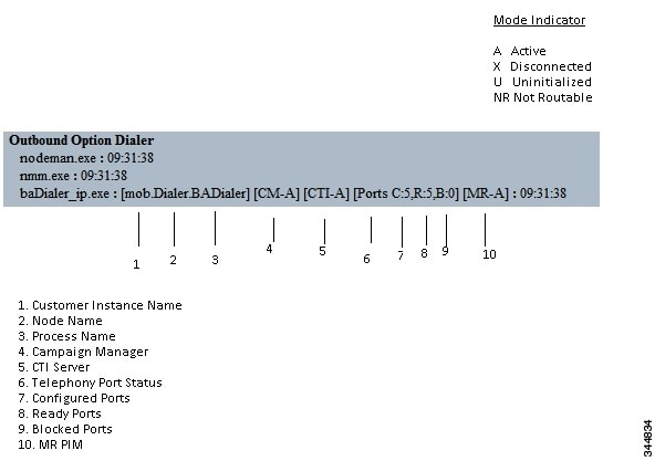
The Dialer component process status provides a lot of details about the health of the installation even before any campaign configuration is initiated or before any call is placed. You can view the Dialer component status in the Diagnostic Framework Portico.
Troubleshoot Dialer Connections
- Dialer customer instance, node name, and process name
- This information is useful if TAC asks you to interrogate the system while debugging a problem for a case.
- Campaign Manager connectivity status
- This status is either A for active or X for disconnected. If the Campaign Manager connectivity status is X, the Dialer is not connected to the Campaign Manager.
Try pinging from the Dialer to the Campaign Manager machine by hostname and by IP Address.
If the ping fails for the IP address, recheck that the IP address is correct, and then troubleshoot network connectivity.
If the ping is successful for the IP address but not for the DNS hostname, check that the DNS hostname is correct and that it is properly configured in the system’s DNS server.
If the ping is successful, recheck the Dialer component setup to see if the Dialer component setup contains the wrong address or port number for the side A Logger.
- CTI Server connectivity status
This status is either A for active or X for disconnected. If the status is X, then the Dialer cannot connect to either CTI Server on side A or side B.
Try pinging from the Dialer to the CTI Server/PG machines by hostname and by IP address.
If the ping fails for the IP address:
If the ping is successful for the IP address but not for the DNS hostname, check that the DNS hostname is correct and that it is properly configured in the system’s DNS server.
If the ping is successful, then recheck the Dialer component set up to see if the Dialer component set up contains the wrong address or port number for the CTI Server.
Confirm that the PG is online. Check that the PG has been enabled properly in the ICM Router setup.
- Dialer ports states
The first value, C, shows the total configured ports derived from the port map configuration. The second value, R, shows the total number of ports registered with Unified CM. Finally, the third value, B, indicates the number of Dialer ports that failed to register with Unified CM. The third value also reports the number of Dialer ports that are blocked. (This is a runtime activity; it is unusual for ports to be blocked.)
If the number of ports Configured is zero, then the Dialer is not receiving port configuration from the Campaign Manager component. Check to verify that ports are configured properly.
If the number of ports Registered is zero, then the Dialer component is having trouble registering with Unified CM.
Check the TFTP server address in the Dialer component setup configuration.
Confirm that the Unified CM is configured correctly. In particular, check if the port map has been imported and the ports have been registered to the JTAPI user for the IPCC PG.
Confirm that the IPCC PG has been started.
Confirm that the JTAPI Gateway has finished configuring. If it has not, wait for it to finish.
Check to see if DNS name (of your PG) is resolving the CUCM IP address
- MR PIM connectivity status
This status is either A for active, X for disconnected, or NR, which means connected but not yet able to route. (The U status is rarely seen and indicates that a particular connectivity object within the Dialer has not been created yet.)
- If the MR Status is X, check the connectivity by performing the following steps:
Ping the MR PG address by hostname or IP address.
Double check the MR PG address and port configured in the Dialer component setup.
If the MR PG status is NR, then the Media Routing connection is established. Check to see if the MR PG is online by looking at its status window.
Verify Critical Configuration Steps
Verify Connectivity
| Step 1 | For an Unified CCE installation, determine the Dialer’s peripheral ID before executing
the DialogicTest utility. This value can be obtained from the Dialer table stored in the
Side A database of the ICM Logger. Using the SQL query analyzer, run the following query on
the Side A database: Select * from Dialer Match the DialerName column with the Dialer that is being configured and note the peripheral ID (stored in the DialerID column). This ID is used when launching DialogicTest.
| ||
| Step 2 | From the \icm\bin directory on the Dialer, type the following to run the DialogicTest
utility, type Dialogictest softphone <number of ports in the Dialer port map>
<CallManager name or IP address> <dialer ID> <starting channelID>
<custname> where:
Example:The following example displays the command syntax and the output log messages. 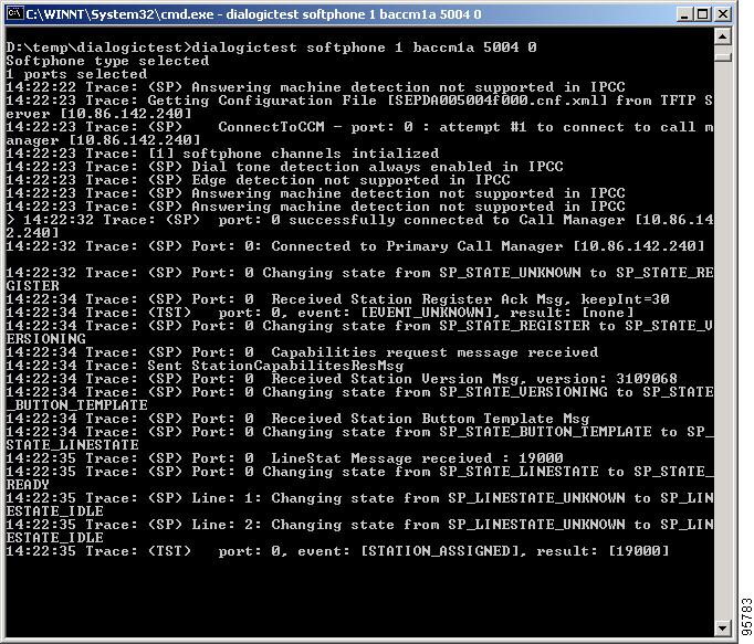 | ||
| Step 3 | Choose a phone station on the ACD that has a "caller ID" display and note its phone
number. This phone station is called to validate connectivity between the Dialer and the
station. Using DialogicTest, dial this station using the following syntax: >d 0 <station #> 30 where d is the abbreviation for "Dial," 0 is the first channel in the port map, station # is the actual number to reach the phone station, and 30 represents the amount of time DialogicTest attempts to ring the phone station. For example, to dial station 51001, the command is >d 0 51001 30. Example:The following example displays the command syntax and the output log messages. 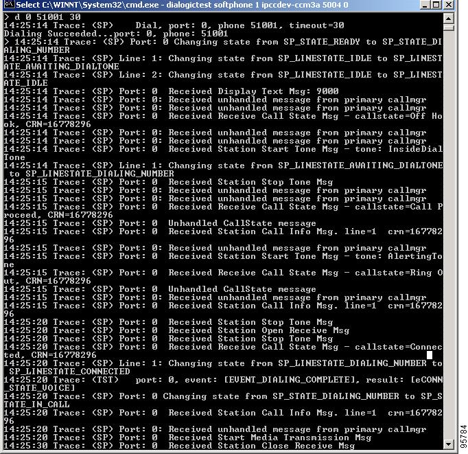 This syntax causes the phone station to ring and display the calling number, which is the station identifier of the first port in the Dialer port map. Answer the phone station and speak into the receiver. The DialogicTest utility notes that voice was detected. If the phone does not ring, the Dialer does not have basic connectivity with the switch and will not work properly. See the Cisco Docwiki for troubleshooting assistance. |
Verify Dialer Port Map Configuration
Note | The Outbound Option IP Dialer must be shut down before running DialogicTest. |
| Step 1 | Beginning with the first port of the port map (channel 0 in
DialogicTest), dial the phone station used for testing above and verify that
the calling number displayed on the station matches the first port configured
in the Dialer port map in Unified ICM software.
Example:For example, to dial station number 1234, use the following command: >d 0 1234 30 |
| Step 2 | Hang up this channel by typing
>h 0 and move to the next channel (channel 1). Dial the phone station again, using a command similar to the following example: Example: >h 0 >d 0 1234 30 Verify that the calling number shown on the station matches the station number configured in the ICM Dialer port map. |
| Step 3 | Hang up this channel by typing
>h 1 and move to channel 2. Continue this
procedure for the entire port map to verify that the station numbers configured
in Unified ICM software match the actual numbers on the switch. If there is a
mismatch in this configuration, the Dialer will not work properly.
If the configuration is a Unified CCE configuration and the BAT tool was used to configure the devices on Unified CM, it is satisfactory to test only a few ports in the range. If the Dialer is connected to a switch using an Analog link, each port must be tested because it is possible to wire this connection incorrectly for a small number of ports. Incorrect wiring creates problems in the Dialer that are difficult to find. |
Verify Database Configuration
|
Verify Router Registry Key
HKEY_LOCAL_MACHINE\SOFTWARE\Cisco Systems, Inc.\ICM\<customer
      instance>\RouterA/B\Router\
      CurrentVersion\Configuration\Global\SkillGroupCallsInQTimerInterval = 2
 Feedback