Cisco IP Phone Key Expansion Module (8800 and 6800)

Cisco 6800 series Key Expansion Module setup overview

The Cisco IP Phone 6851 Multiplatform Phone supports only one key expansion module. The key expansion module provides 14 lines or programmable buttons, and two pages. Each page contains 14 lines or buttons.

Cisco 8800 series Key Expansion Module setup overview

Figure 1. Key Expansion Module with Single LCD Screen
Figure 2. Cisco IP Phone 8851/8861 Key Expansion Module with Dual Screen
Cisco IP Phone 8851/8861 Key Expansion Module
Figure 3. Cisco IP Phone 8865 Key Expansion Module with Dual Screen
Cisco IP Phone 8865 Key Expansion Module

The Cisco IP Phone 8800 Key Expansion Module adds extra programmable buttons to the phone. The programmable buttons can be set up as phone speed-dial buttons, or phone feature buttons.

There are 3 expansion modules available:
  • Cisco IP Phone 8800 Key Expansion Module—Single LCD screen module, 18 line keys, 2 pages, two-column display only.

  • Cisco IP Phone 8851/8861 Key Expansion Module—Dual LCD screen module for audio phones, 14 line keys, 2 pages, one-column display only.

  • Cisco IP Phone 8865 Key Expansion Module—Dual LCD screen module for video phones, 14 line keys, 2 pages, one-column display only.


Note


The Cisco IP Phone 8851/8861 Key Expansion Module and the Cisco IP Phone 8865 Key Expansion Module require Firmware Release 11.2(3) or later.


You can use more than one expansion module per phone. But each module must be the same type. You cannot mix Cisco IP Phone 8800 Key Expansion Module with a Cisco IP Phone 8851/8861 Key Expansion Module or with a Cisco IP Phone 8865 Key Expansion Module. You cannot mix audio expansion modules with video expansion modules. You also cannot use a video expansion module on an audio phone or an audio expansion module on a video phone.

The following table lists the phones and the number of key expansion modules that each model supports.

Table 1. Cisco IP Phones and Supported Cisco IP Phone 8800 Key Expansion Module

Cisco IP Phone Model

Supported Number of Key Expansion Modules and Buttons

Cisco IP Phone 8851

2; single LCD screen, 18 line keys, two pages, providing 72 buttons

Cisco IP Phone 8861

3; single LCD screen, 18 line keys, two pages, providing 108 buttons

Cisco IP Phone 8865

3; single LCD screen, 18 line keys, two pages, providing 108 buttons,

Table 2. Cisco IP Phones and Supported Cisco IP Phone 8851/8861 Key Expansion Module and Cisco IP Phone 8865 Key Expansion Module

Cisco IP Phone Model

Supported Numbers of Key Expansion Modules and Buttons

Cisco IP Phone 8851

2; dual LCD screen, 14 line keys, two pages, providing 56 buttons

Cisco IP Phone 8861

3; dual LCD screen, 14 line keys, two pages, providing 84 buttons

Cisco IP Phone 8865

3; dual LCD screen, 14 line keys, two pages, providing 84 buttons

Auto Detection of Key Expansion Modules (8800 0nly)

You can configure a new phone to auto-detect the maximum number of key expansion modules that it supports. For these phones, the Number of Units field shows the maximum number of key expansion modules that the phone supports as the default value. When a user adds key expansion modules to these phones, the module lights up and is enabled automatically. Default value of this field is 2 for Cisco IP Phone 8851 and 3 for Cisco IP Phone 8861. Navigate to Admin Login > Advanced > Voice > Att Console to check the value of the Number of Units field.

If your user has an older release phone and it is upgraded to the current release, you can change the cofiguration of the phone so that when the user adds a key expansion module to the phone, it lights up and is enabled automatically.

Configure the Key Expansion Module with the Phone Web Interface

You can add number of supported key expansion modules from the phone web interface.

You can also configure the parameters in the phone configuration file with XML(cfg.xml) code.

Before you begin

Access the phone administration web page. See Access the Phone Web Interface.

Procedure


Step 1

Select Voice > Att Console.

Step 2

From the Number of Units list, select 1 as the number of supported key expansion modules.

You can also configure the parameter in the configuration file (cfg.xml) by entering a string in the following format:

<Number_of_Units ua="na">2</Number_of_Units>

Default: 0

Step 3

Click Submit All Changes.


Access Key Expansion Module Setup

After you install one or more key expansion modules on the phone and configure them in the Configuration Utility page, the phone automatically recognizes the key expansion modules.

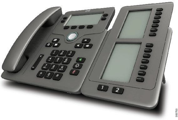
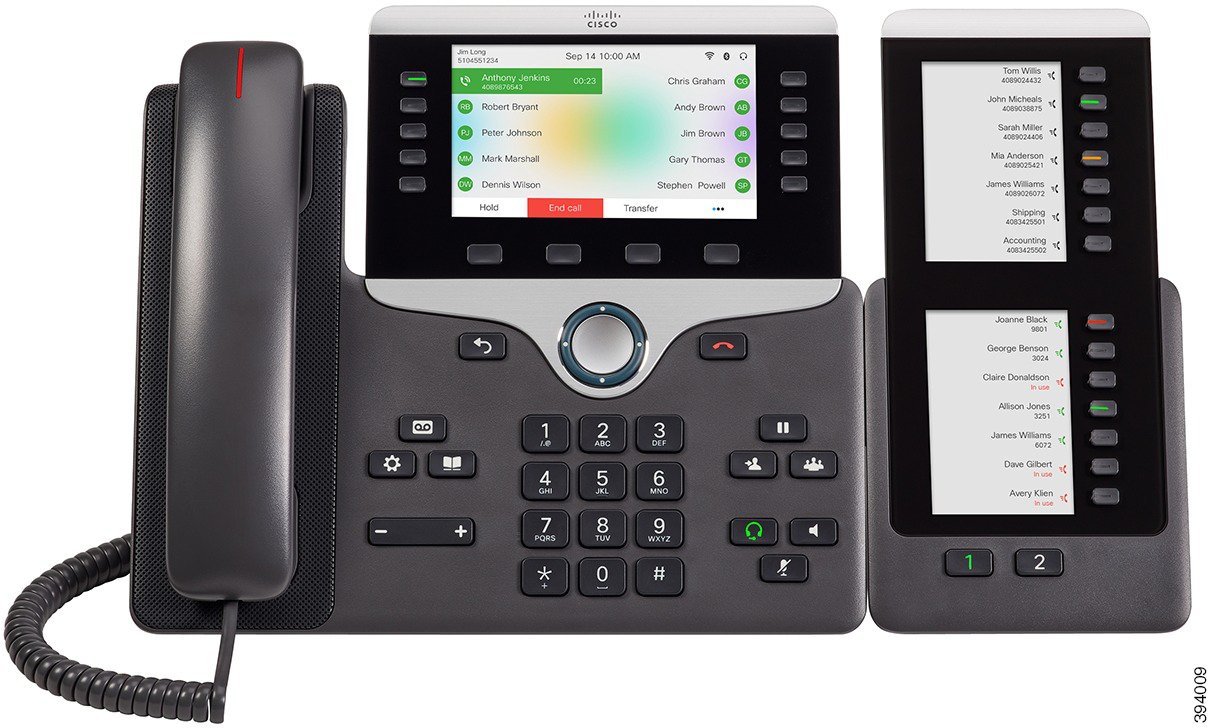
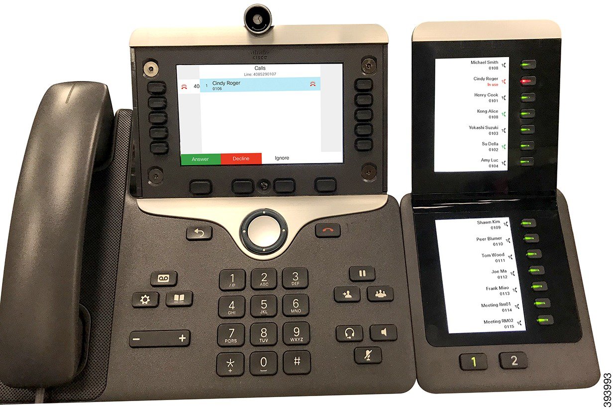
When multiple key expansion modules are attached, they are numbered according to the order in which they connect to the phone:

  • Key expansion module 1 is the expansion module closest to the phone.

  • Key expansion module 2 is the expansion module in the middle.

  • Key expansion module 3 is the expansion module farthest to the right.

When the phone automatically recognizes the key expansion modules, you can then choose the Show Details softkey for additional information about the selected key expansion module.

    Procedure


    Step 1

    On the phone, press Applications .

    Step 2

    Press Status > Accessories.

    All properly installed and configured key expansion modules display in the list of accessories.


    Allocate a Key Expansion Module Type (8800 only)

    You can assign the type of key expansion module that the phone supports:

    • BEKEM

    • CP-8800-Audio

    • CP-8800-Video

    You can also configure the parameters in the phone configuration file with XML(cfg.xml) code.

    Before you begin

    Procedure


    Step 1

    Select Voice > Att Console.

    Step 2

    Set the KEM Type from BEKEM, CP-8800-Audio, and CP-8800-Video

    You can also configure the parameter in the configuration file (cfg.xml) by entering a string in the following format:

    <KEM_Type ua="na">CP-8800-Video</KEM_Type>

    Options: BEKEM, CP-8800-Audio, and CP-8800-Video

    Default: CP-8800-Video

    Step 3

    Press Submit All Changes.


    Allocate a Key Expansion Module type with the phone menu

    You can assign the type of key expansion module that the phone supports.

    Procedure


    Step 1

    Press Applications .

    Step 2

    Select User preferences > Attendant console preferences > KEM type.

    Step 3

    Select the key expansion module type.

    Step 4

    Press Save.


    Reset the Single LCD Screen Key Expansion Module (8800 only)

    If you are having technical difficulties with your Cisco IP Phone 8800 Key Expansion Module, you can reset the module to the factory default settings.

    Procedure


    Step 1

    Restart the key expansion module by disconnecting the power source, waiting a few seconds, and then reconnecting it.

    Step 2

    As the key expansion module powers up, press and hold Page 1. As the LCD screen turns white, continue pressing Page 1 for at least one second.

    Step 3

    Release Page 1. The LEDs turn red.

    Step 4

    Immediately press Page 2 and continue pressing Page 2 for at least one second.

    Step 5

    Release Page 2. The LEDs turn amber.

    Step 6

    Press Lines 5, 14, 1, 18, 10, and 9 in sequence.

    The LCD screen turns blue. A spinning icon is displayed in the center of the screen.

    The key expansion module resets.


    Configure a Speed Dial on a Key Expansion Module

    You can configure speed dial on a key expansion module line. The user can then press the line key to call a frequently dialed number.

    You can also configure the parameters in the phone configuration file with XML(cfg.xml) code.

    Before you begin

    Access the Phone Web Interface.

    Procedure


    Step 1

    Select Voice > Att Console.

    Step 2

    Select a key expansion module line key on which to enable the speed dial.

    Step 3

    Enter a string in this format:

    fnc=sd;ext=9999@$PROXY;vid=n;nme=xxxx

    where:

    • fnc= sd means function=speed dial

    • ext= 9999 is the phone that the line key calls. Replace 9999 with numbers.

    • vid=n is the line index of the phone.

    • nme= XXXX is the name displayed on the phone for the speed-dial line key. Replace XXXX with a name.

    You can also configure the parameter in the configuration file (cfg.xml) by entering a string in the following format:

    <Unit_n_Key_m>fnc=sd;ext=9999@$PROXY;vid=n;nme=xxxx

    Step 4

    Click Submit All Changes.


    Add Call Park on a Key Expansion Module Line Key

    You can enable call park on a key expansion module line. The user can then use the line to park a call. and then retrieve the call either from own phone or another phone.

    Before you begin

    Access the phone administration web page. See Access the Phone Web Interface.

    Procedure


    Step 1

    Select Voice > Att Console.

    Step 2

    Select a Key Expansion Module line key on which to enable the call park.

    Step 3

    Enter a string in this format:

    For a private line, enter
    fnc=park;sub=$USER@$PROXY;nme=CallPark-Slot1
    For a shared line, enter
    fnc=prk;sub=$USER@$PROXY;nme=Call-Park1;orbit=<DN of primary line>

    where:

    • fnc= prk means function=call park

    • sub= 999999 is the phone to which the call parks. Replace 999999 with a numbers.

    • nme= XXXX is the name displayed on the phone for the call park line key. Replace XXXX with a name.

    You can also configure the line-specific parameter in the configuration file (cfg.xml). Enter a string in the following format:
    <Unit_1_Key_1_ ua="na">fnc=prk;sub=$USER@$PROXY;nme=CallPark-Slot1</Unit_1_Key_1_>

    Step 4

    Click Submit All Changes.


    Configure the LCD Brightness for a Key Expansion Module

    You can configure the brightness of the LCD display on the key expansion module from the Attendant Console tab.

    You can also configure the parameters in the phone configuration file with XML(cfg.xml) code.

    Before you begin

    Access the phone administration web page. See Access the Phone Web Interface.

    Procedure


    Step 1

    Select Voice > Att Console.

    Step 2

    Set the Attendant Console LCD Contrast to a value between 1 and 15.

    You can also configure the parameter in the configuration file (cfg.xml) by entering a string in the following format:

    <Attendant_Console_LCD_Brightness ua="na">12</Attendant_Console_LCD_Brightness>

    The higher the number, the greater the brightness on the key expansion module screen. The default value is 12. If no value is entered, the LCD brightness level is equal to 1, the dimmest value.

    Step 3

    Click Submit All Changes.


    Adjust the Contrast of Key Expansion Module LCD from the Phone Web Page

    You can adust the LCD contrast of the Key Expansion Module from the phone web page and the value gets updated on the phone. You can modify this value from the phone.

    Before you begin

    Access the phone administration web page. See Access the Phone Web Interface.

    Procedure


    Step 1

    Select Voice > Att Console.

    Step 2

    In the General section, enter a value in the Attendant Console LCD Contrast field.

    Valid values: 4 to 12

    Step 3

    Click Submit All Changes.


    Configure the Busy Lamp Field on a Key Expansion Module

    You can configure the busy lamp field on a key expansion module line so that the user can monitor a coworker's availability to receive a call.

    Before you begin

    Access the phone administration web page. See Access the Phone Web Interface.

    Procedure


    Step 1

    Select Voice > Att Console.

    Step 2

    Select a key expansion module line key.

    Step 3

    Enter a string in this format:

    fnc=blf;sub=xxxx@$PROXY;usr=8888@$PROXY.

    Where:

    • fnc= blf means function=busy lamp field
    • sub= the URI to which the SUBSCRIBE message is sent. This name must be identical to the name defined in the List URI: sip: parameter. xxxx is the name that is defined in List URI: sip: parameter. Replace xxxx with the exact defined name. $PROXY is the server. Replace $PROXY with the server address or name.
    • usr= the BroadSoft user being monitored by BLF with 8888 as the phone being monitored. Replace 8888 with the exact number of the monitored phone. $PROXY is the server. Replace $PROXY with the server address or name.

    Step 4

    (Optional) To enable the busy lamp field to work with both speed dial and call pickup enter a string in the following format:

    fnc=blf+sd+cp;sub=xxxx@$PROXY;usr=yyyy@$PROXY.

    Where:

    sd= speed dial

    cp= call pickup

    You can also enable busy lamp field only with call pickup or speed dial. Enter the string in the following format:

    fnc=blf+cp;sub=xxxx@$PROXY;usr=yyyy@$PROXY

    fnc=blf+sd;sub=xxxx@$PROXY;usr=yyyy@$PROXY

    You can also configure the parameter in the configuration file (cfg.xml) by entering a string in the following format:

    <Unit_1_Key_2_ ua="na">fnc=blf;ext=3252@$PROXY;nme=BLF_3252</Unit_1_Key_2_>

    Step 5

    Click Submit All Changes.


    Enable the User to Configure Features on Key Expansion Module Line Keys

    You can enable the user to configure features on the line keys of the key expansion module. The user can then add any of the configured features to the dedicated line keys. For the supported features, see Configurable Features on Line Keys.

    Before you begin

    • Access the phone administration web page. See Access the Phone Web Interface.

    • Ensure that the line keys of the key expansion module are not in the Inert mode.

    Procedure


    Step 1

    Select Voice > Att Console.

    Step 2

    In the General section, configure the Customizable PLK Options parameter with the codes of your desired features defined in Configurable Features on Line Keys.

    Example: You configure this parameter with blf;shortcut;dnd;. The user can call up the feature list with a long-press on a key expansion module line key. The feature list looks like:

    1 None

    2 BLF presence

    4 Menu shortcut

    3 Do not disturb

    The user can then select a feature or a menu shortcut to add to the line key.

    You can also configure this parameter in the configuration file (cfg.xml) with a string in this format:
    <Customizable_PLK_Options ua="na">blf;shortcut;dnd;</Customizable_PLK_Options>

    Step 3

    Click Submit All Changes.


    Assign an Extension Number to a Key Expansion Module (KEM) Line Key (8800 only)

    You can assign an extension number to a key expansion module line key so that the line key can be used as a SIP line. For a line key, you can enable an extension number that ranges from 1 to 16. You can use this line key for phone features such as make a call, answer a call, or add more than one person to a conference call. Only audio key expansion module and video key expansion module support this feature.

    Phone line keys also support 16 extensions.

    Before you begin

    Procedure


    Step 1

    Select Voice > Att Console .

    Step 2

    Under Unit [m] Line key [n], select an extension number (1 to 16) from the Extension list.

    Here, in Unit (m) Line key [n], [m] is the unit number that ranges from 1 to 3 for Cisco IP phone 8861 and 8865 and 1 to 2 for Cisco IP phone 8851. [n] is the line key number that ranges from 1 to 28. As Cisco IP phone 8851 support two key expansion modules and Cisco IP phone 8861 and 8865 can support three key expansion modules, each key expansion module has 28 lines keys and [n] ranges from 1 to 28. You can view all line keys in the Att Console page.

    For example, you assign Ext 1 to Unit 1 Line Key 1 and Ext 16 to Unit 1 Line Key 2. After the line keys are successfully assigned, on the key expansion module, the line key 1 displays Extension number 1 and the line key 2 displays Extension number 16 respectively.

    Under Info > Status, you can view the status of all 16 extensions.

    Step 3

    Click Submit All Changes.

    When the extension number is successfully assigned to the line key, user can see the key expansion module line key is registered with a SIP line.

    Add a Menu Shortcut to a Key Expansion Module Line Key

    You can add a menu shortcut to a line key of the attached key expansion module. Then, the user can press the configured line key to access the menu.

    Before you begin

    Access the phone administration web page. See Access the Phone Web Interface.

    Procedure


    Step 1

    Select Voice > Att Console.

    Step 2

    Go to the Unit (n) section, where n is unit number of the key expansion module.

    Step 3

    Configure the Unit n Key m field, where n is unit number of the key expansion module, and m is the key number.

    fnc=shortcut;url=userpref;nme=User preferences

    where:

    • fnc= shortcut means function=phone menu shortcut.

    • url= userpref is the menu to open with this line key. It's the User preferences menu in this example. For more shortcut mappings, see Menu Shortcuts Mapping on PLK and PSK.

    • nme= XXXX is the menu shortcut name displayed on the key expansion module screen. If you don't specify a display name, the line key displays the target menu item. In the example, the line key displays User preferences.

    You can also configure the parameter in the configuration file (cfg.xml) with a string in this format:

    <Unit_n_Key_m_ ua="na">fnc=shortcut;url=userpref;nme=User preferences</Unit_n_Key_m_>

    where n is the unit number of the key expansion module, and m is the key number.

    Step 4

    Click Submit All Changes.


    Add an Extended Feature to a Key Expansion Module Line Key

    You can add a feature to a line key of the attached key expansion module. Then, the user can press the line key to access the feature. For the supported features, see Configurable Features on Line Keys.

    Before you begin

    Access the phone administration web page. See Access the Phone Web Interface.

    Procedure


    Step 1

    Select Voice > Att Console.

    Step 2

    Go to the Unit (n) section, where n is unit number of the key expansion module.

    Step 3

    Configure the Unit n Key m field, where n is unit number of the key expansion module, and m is the key number.

    fnc=dnd

    The user can turn on or off Do not disturb mode with the line key. For more feature codes, see Configurable Features on Line Keys.

    You can also configure the parameter in the configuration file (cfg.xml) with a string in this format:

    <Unit_n_Key_m_ ua="na">fnc=dnd</Unit_n_Key_m_>

    where n is the unit number of the key expansion module, and m is the key number.

    Step 4

    Click Submit All Changes.


    Configure the Voicemail PLK on a Key Expansion Module Button

    You can configure the voicemail Programmable Line Key (PLK) on a Key Expansion Module button for the users to monitor a specified voicemail account of a user or a group.

    The voicemail PLK can monitor both the voicemail of an extension and the voicemail account of another user or a group. Monitoring the voicemail of another user or a group requires the support from the SIP proxy.

    For example, if the users belong to a customer service group. This feature allows the users to monitor both their voicemails and the group's voicemails.

    If you configure speed dial for the same button, the users can press the button to make a speed dial to the assigned extension.

    Before you begin

    One or more expansion modules have been installed on the phone.

    Access the phone administration web page. See Access the Phone Web Interface.

    Procedure


    Step 1

    Select Voice > Att Console.

    Step 2

    Select an expansion module button on which to configure the voicemail PLK.

    Step 3

    Enter a string in this format:

    • For MWI only:

      fnc=mwi;sub=group_vm@domain;vid=1;nme=Group;
    • For MWI + Speed Dial:

      fnc=mwi+sd;ext=8000@domain;sub=group_vm@domain;vid=1;nme=Group;
    • For MWI + speed dial + DTMF:

      fnc=mwi+sd;ext=8000 ,4085283300#,123456#@domain;sub=group_vm@domain;vid=1;nme=Group;

    For more information about the string syntax, see String Syntax for Voicemail PLK.

    You can also configure this parameter in the phone configuration file (cfg.xml). The parameter is line-specific. Enter a string in this format:

    <Unit_1_Key_1_ ua="na">fnc=mwi+sd;ext=8000 ,4085283300#,123456#@domain;
    sub=group_vm@domain;vid=1;nme=Group;</Unit_1_Key_1_>
    

    Step 4

    In the General section, add mwi or mwi;sd in the field Customizable PLK Options.

    Parameter in the configuration file (cfg.xml):

    <Customizable_PLK_Options ua="na">mwi;sd</Customizable_PLK_Options>

    After the configuration, users can configure the corresponding features on the expansion module button.

    Step 5

    Click Submit All Changes.


    Troubleshoot the Key Expansion Module

    Procedure


    Step 1

    Open a CLI.

    Step 2

    Enter the following command to enter debug mode:

    debugsh

    Step 3

    Enter ? to see all available commands and options.

    Step 4

    Use the applicable commands and options to find the desired information.

    Step 5

    To exit debug mode, press Ctrl-C.


    Key Expansion Module Does Not Go Through the Normal Start Up Process

    Problem

    When you connect a key expansion module to a phone that is connected to a network port, the key expansion module doesn't start up.

    Cause

    • Key expansion module type and the attached key expansion module don't match.

    • The phone has more than one type of expansion module connected.

    • Power over Ethernet (PoE) doesn't meet the required power-supply.

    • Connected number of key expansion modules exceed maximum "Number of Units".

    Solution

    • Change the phone to use the same type of expansion module.

    • Check the PoE the phone connected to.

    • Check if the unit number is bigger than the “Number of Units".

    Shut Down a Line Key on a Key Expansion Module

    You can shut down a line key on a key expansion module by setting the Inert mode for it from the phone web page. When the key expansion module line key is in the Inert mode, it is disabled thoroughly. For example, the key expansion module LED is disabled (including LED behavior), no icon or text displays next to the key expansion module line key, and the key expansion module button is not responsive. In a word, it is completely unavailable.

    Before you begin

    Access the phone administration web interface. See Access the Phone Web Interface

    Procedure


    Step 1

    Select Voice > Att Console.

    Step 2

    Go to the Unit (n) section, where n is unit number of the key expansion module.

    Step 3

    Configure the Unit n Key m field, where n is unit number of the key expansion module, and m is the key number.

    fnc=inert;

    where fnc=inert means function=inert.

    You can also configure the parameter in the configuration file (cfg.xml) with a string in this format:

    <Unit_n_Key_m_ ua="na">fnc=inert;</Unit_n_Key_m_>

    where n is the unit number of the key expansion module, and m is the key number.

    Step 4

    Click Submit All Changes.