Hardware Installation

Installation Requirements

The Cisco IP DECT 6800 Series is made up of the following hardware:

  • 6825 Handset

  • 6825 Ruggedized Handset

  • 6823 Handset

  • 110 Single-Cell Base Station

  • 210 Multi-Cell Base Station

  • 110 Repeater


Note


The 110 Single-Cell Base Station can't be used in the multicell system.


Before you begin to set up the Cisco IP DECT 6800 Series system:

  • Determine the number of users (handsets) that are required.

  • Determine the number of phone lines (numbers) that are required. Each user can have up to 2 lines and 2 concurrent calls, if the supported total number of concurrent calls on the system aren’t reached.

  • Given the number of handsets, determine the number of base stations required, based on:

    • Estimated simultaneous handset usage: For more information, see Handset Registrations.

    • Size of the space covered.

    • Range of the base stations. Each base station has a range of up to 984 feet (300 meters) outdoors and a range of 164 feet (50 meters) indoors.

    • If required, you can add repeaters to the base station to extend the range of the system:

      Table 1. Maximum Number of Repeaters for the Base Stations

      Base Stations

      Repeaters

      110 Single-Cell Base Station

      6

      210 Multi-Cell Base Station

      3

      Range of the repeaters. Each repeater has a range of up to 984 feet (300 meters) outdoors and a range of 164 feet (50 meters) indoors.

    For more information to determine the number of base stations, repeaters and handsets for the coverage area, see Cisco IP DECT Phone 6800 Series Deployment Guide.

  • The call control system must be set up and operational. Obtain the call control system information, including server addresses, user ids, and passwords. You may find Worksheets useful when you collect the information.

  • Plan the location to install each base station.

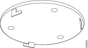
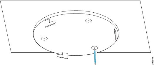
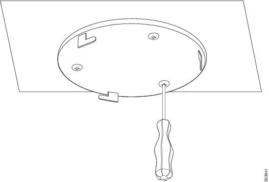
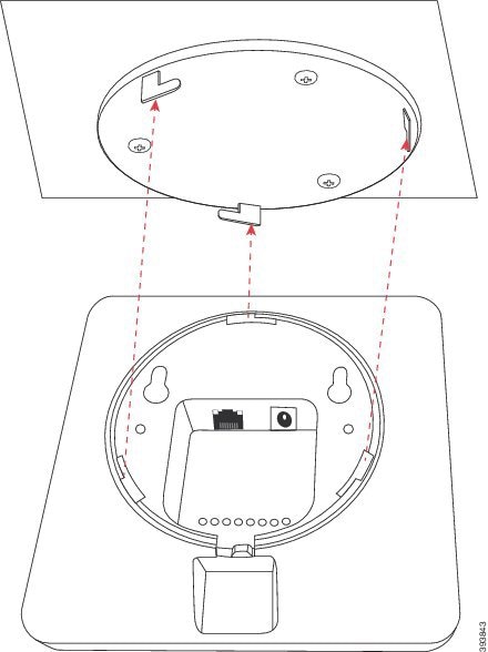
    • Determine if you need to mount the base stations on walls or on the ceiling.

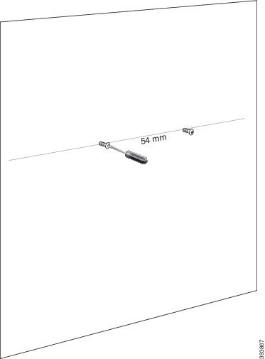
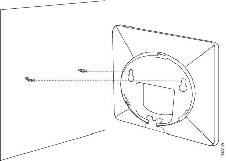
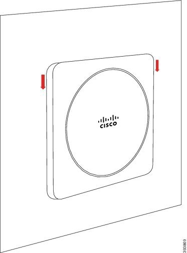
      We provide wall plugs and screws to mount the base station on drywall (plasterboard).

    • Ensure that there’s a LAN connection close to the planned location of each base station. The Ethernet cable included with the base is 78.5 inches (200 cm) but you can use up to 3937 inches (10,000 cm) length of straight-through CAT5e cable.

    • If you don’t use Power over Ethernet (PoE), install the base station near the electrical outlet located in an area that provides a good coverage for the base station. The length of the power cord with the adapter is 82 inches (208 cm).

    • Determine that the base stations are placed so that handsets can communicate. Make sure that the coverage is optimal for your users.

      With the 110 Single-Cell Base Station, you can add repeaters to improve the coverage.

      With the 210 Multi-Cell Base Station, you can add additional base stations or repeaters to improve coverage.

  • If repeaters are required:

    • Determine if you need to mount the repeaters on walls or on the ceiling.

      We provide wall plugs and screws to mount the repeater on drywall (plasterboard). See the mounting procedures for further information.

    • Ensure that there’s an electrical outlet close to the planned location of each repeater. The length of the power cord with the adapter is 82 inches (208 cm).

    • Ensure that the repeater is within the range of the base station. Each base station has a range of up to 984 feet (300 meters) outdoors and a range of 164 feet (50 meters) indoors.

Handset Registrations

You can have up to 20 handsets registered on a 110 Single-Cell Base Station and 30 handsets registered on a 210 Multi-Cell Base Station. However, the number of active calls the base station can handle is limited by the codec.

Table 2. Number of Active Calls Supported for one 110 Single-Cell Base Station and one 210 Multi-Cell Base Station

Band

110 Single-Cell Base Station 210 Multi-Cell Base Station

Concurrent Narrowband

10 10

Concurrent Secure Narrowband

10

8

Wideband

5

5

Table 3. Number of Active Calls Supported for two 110 Single-Cell Base Stations and two 210 Multi-Cell Base Stations

Band

110 Single-Cell Base Station 210 Multi-Cell Base Station

Concurrent Narrowband

20

16

Concurrent Secure Narrowband

20

16

Wideband

10

10

Table 4. Maximum Number of Active Calls Supported for many 210 Multi-Cell Base Stations

Band

Multicell System

Concurrent Narrowband

2000

Concurrent Secure Narrowband

2000

Wideband

1250


Note


If a user turns on Push to Talk, the base station may reduce the supported number of active calls.


Note


If you use repeaters, the base supports less active handsets.


The single cell, dualcell, and multicell deployments have different maximum numbers of handsets and base stations. For more information, see Single Cell, Dualcell, and Multicell Networks.

Single Cell, Dualcell, and Multicell Networks

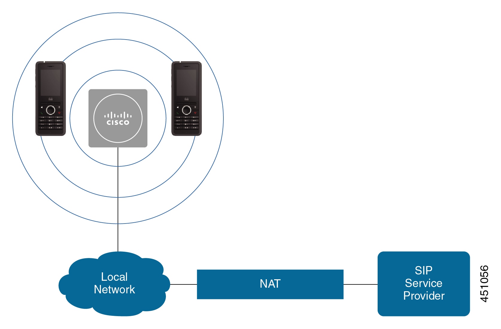
You can set up either a single cell system, a dualcell system, or a multicell system.

A single cell system consists of either one 110 Single-Cell Base Station with up to 20 handsets or 210 Multi-Cell Base Station with up to 30 handsets. You can also use up to 6 of the 110 Repeaters with 110 Single-Cell Base Station and up to 3 of the 110 Repeaters with 210 Multi-Cell Base Station for improved radio coverage. The following diagram shows a single cell network with one base station.

Figure 1. Single Cell Network
diagram showing a base station and handsets in the network

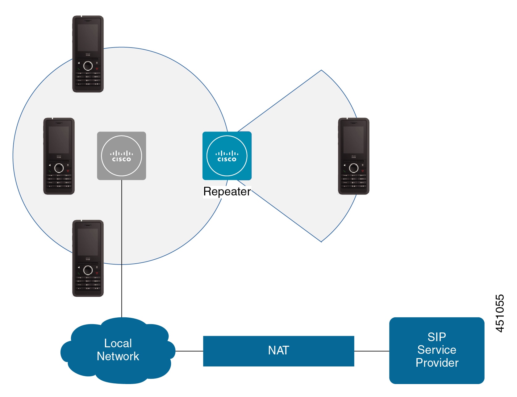
The following diagram shows a single cell base station with one repeater.

Figure 2. Single Base Station with One Repeater
diagram showing a base station and repeater in the network

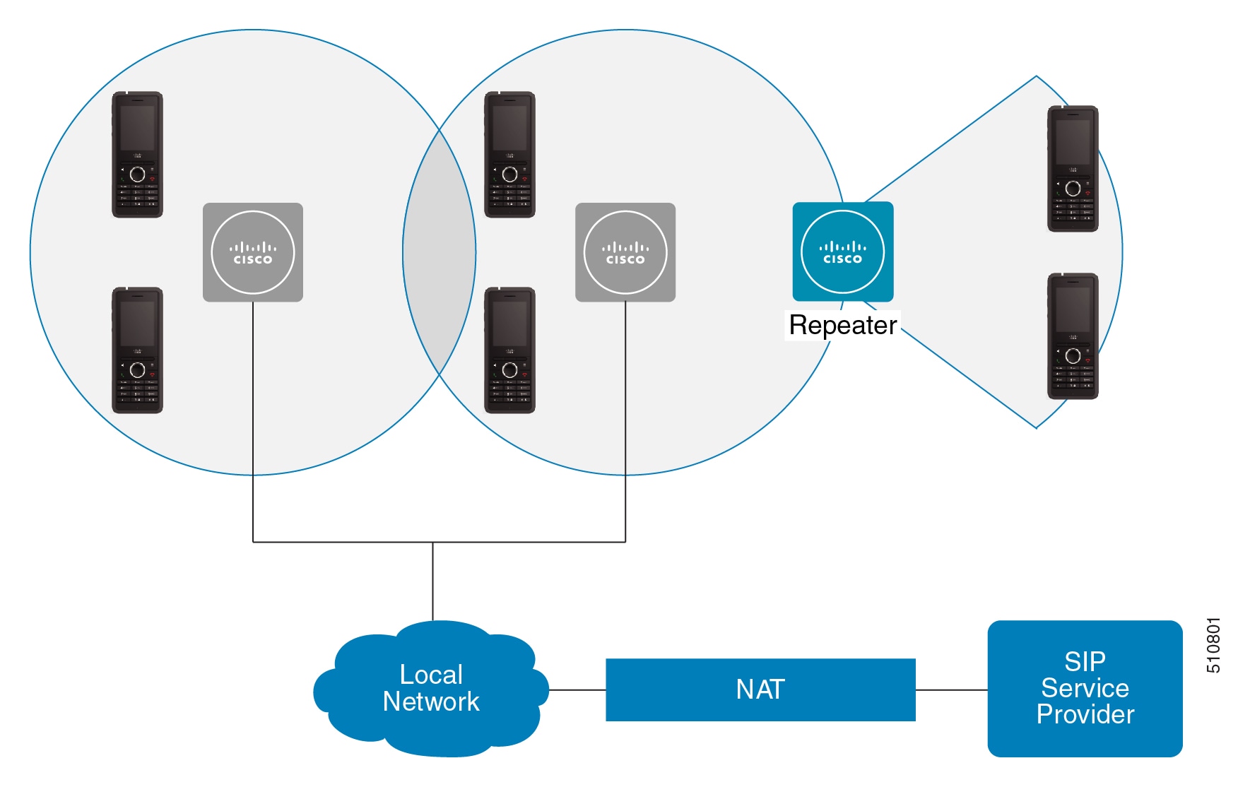
A dualcell system consists of two of the 110 Single-Cell Base Stations with up to 30 handsets. In this system, you can also use up to 12 of the 110 Repeaters for improved radio coverage. The following diagram shows two base stations with one repeater.

Figure 3. Dualcell Network
diagram showing two base stations with handsets and repeater in the network

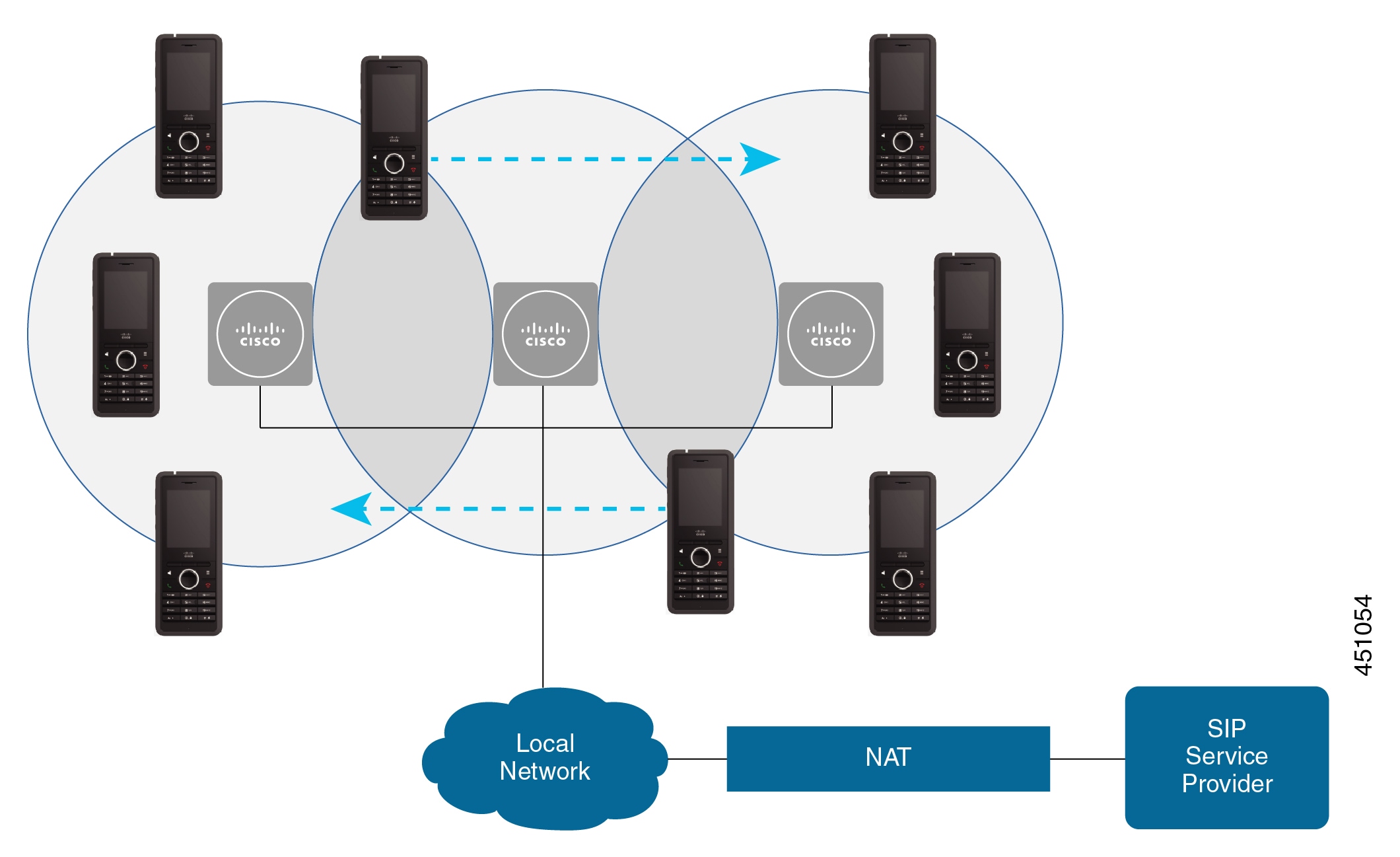
A multicell system consists of two of the 210 Multi-Cell Base Stations with up to 60 handsets or up to 250 of the 210 Multi-Cell Base Stations with up to 1000 handsets. In this system, you can also use up to 6 of the 110 Repeaters with two base stations or 100s of the 110 Repeaters with 250 of the base stations for improved radio coverage. The following diagram shows a multicell network with 3 base stations.

Figure 4. Multicell Network
diagram showing three base stations with handsets in the network

Base Station Package Contents

Your base station package has the following contents:

  • Base station

  • Base station stand

  • Ethernet cable

  • Regional power adapter

  • USB-to-power jack cable

  • Mounting screws and plugs

  • Printed compliance document

If you want to mount the base station on the ceiling, you need to order a separate ceiling mount kit.

Repeater Package Contents

Your repeater package has the following contents:

  • Repeater

  • Repeater stand

  • Regional power adapter

  • USB-to-power jack cable

  • Mounting screws and plugs

  • Printed compliance document

If you want to mount the repeater on the ceiling, you need to order a separate ceiling mount kit.

Handset package contents

Your handset package has the following contents:

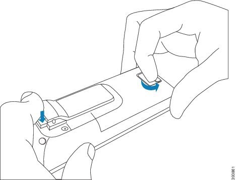
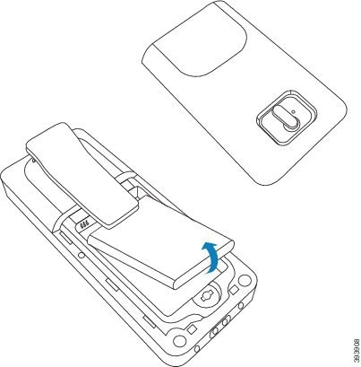
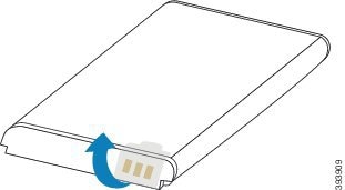
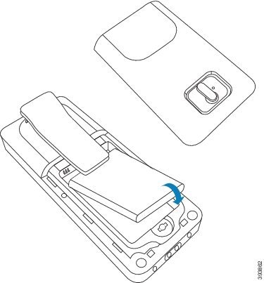
  • Handset with attached belt clip. Inside the handset is the battery, with a piece of plastic over the battery contacts.


    Note


    You need to remove the plastic over the battery contacts. For more information, see Install the battery in the handset.


  • Charging cradle with attached USB cable.

  • Regional power adapter for the charging cradle.

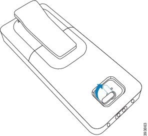
  • Plastic cover to replace the belt clip on the handset.


    Note


    Make sure that you save this small plastic cover, in case you want to use the handset without the belt clip.


  • Printed compliance document.

You need the label on the box during handset registration.

Power Requirements

The base station requires one of these power sources:

  • Power over Ethernet (PoE) - minimum IEEE 802.3: Power class 2 (3.84 – 6.49W)

  • Power adapter specific to your region with a USB-to-power jack cable. The power adapter is plugged into an electrical outlet.

The handset is powered by a 3.7V, 1000mAh, 4.1Wh, Lithium ion battery.

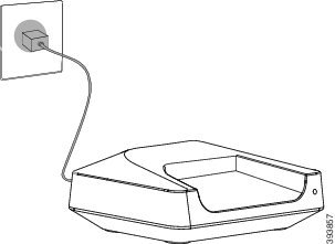
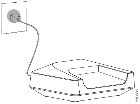
The handset charger power cable plugs into the regional power adapter, and the power adapter must be plugged into an electrical outlet.

Install the Base Station

When the base station connects to the network, the LEDs light to indicate the network status:

  • Green—Connected.

  • Amber—Connection in progress.

  • Red, flashing—Can't connect to the network.

  • Red, solid—Network connection resetting.

Use this procedure to check that the base station and the network can communicate with each other, before you mount the base station in the chosen location.

Before you begin

The base station requires:

  • Power over Ethernet (PoE) or a power adapter

  • LAN connection

  • An IP address assigned by DHCP in the network

Procedure


Step 1

Plug one end of the Ethernet cable into the base station.

Step 2

Plug the other end of the Ethernet cable into the LAN port.

Step 3

If you don't use PoE, plug the power adapter into the base station and then into the electrical outlet.

Step 4

If the LED flashes red after a few minutes, do these steps:

  1. Locate the Reset button on the bottom edge of the base station.

  2. Press and hold Reset until the LED is a solid red.

  3. Release Reset.

    The LED should flash amber and then try to connect. If the LED doesn't light green, then the base station can't get an IP address. See Base Station LED is Solid Red for further help.


What to do next

Mount the base station with one of these procedures:

Mount the base station or repeater on the ceiling

You can mount the base station or repeater on a ceiling. They use a custom ceiling mount bracket that you can install on the ceiling. You need to order the ceiling mount bracket.

Figure 5. Ceiling Mount Bracket

The base station and repeater have a range of up to 984 feet (300 meters) outdoors and a range of 164 feet (50 meters) indoors.

In this task, the term device means the base station or repeater.

Before you begin

You need:

  • Ceiling mount bracket

  • Pencil

  • Mounting hardware (screws and plugs) suitable for the ceiling construction.

  • Base station: LAN connection close to the mounting location.

  • Base station: If you do not use PoE, a power outlet close to the mounting location.

  • Repeater: A power outlet close to the mounting location.

  • Ensure that the base station can communicate with the network (see Install the Base Station). After it can communicate and the LED is green, you can unplug the cables.

Determine the best placement, taking into account the coverage area and the building construction materials.

  • If you have a 110 Single-Cell Base Station, you may need to add another 110 Single-Cell Base Station or additional 110 Repeaters.

  • If you have a 210 Multi-Cell Base Station, you may need to add additional base stations or repeaters.

You can use the site survey tool on the handset to plan placement.

Procedure


Step 1

Hold the ceiling mount bracket in the desired location.

Step 2

Mark the screw placement.

Step 3

Install the plugs as described by the manufacturer.

Step 4

Install the screws through the bracket and into the plugs.

Step 5

Base station only: Connect the Ethernet cable to the device and route the cable through the slot in the device.

Step 6

Provide power to the device:

  • Base station with PoE on the LAN: Additional power is not required.
  • Base station without PoE: Plug the power adapter into the base station and route the cable through the slot in the base station.
  • Repeater: Plug the power adapter into the repeater and route the cable through the slot in the repeater.

Step 7

Align the slots in the bracket with the slots in the device and turn left until the device locks in place.

This graphic shows the alignment of the mounting bracket to the base station. The back of the repeater is similar to the base station.

This diagram shows the way you turn the device to lock it into the mounting bracket.

Step 8

Base station only: Plug the Ethernet cable into the LAN port.

Step 9

If required, plug the power adapter into the electrical outlet.


What to do next

Do one of these:

Mount the base station or repeater on a desk

You can place the base station or repeater on a desk or other horizontal surface (for example, a book shelf). Select a location where the base station or repeater won't be easily knocked off.

The base station and repeater have a range of up to 984 feet (300 meters) outdoors and a range of 164 feet (50 meters) indoors.

In this task, the term device means the base station or repeater.

Before you begin

You need:

  • Base station: LAN connection close to the mounting location.

  • Base station: If you do not use PoE, a power outlet close to the mounting location.

  • Repeater: A power outlet close to the mounting location.

  • Ensure that the base station can communicate with the network (see Install the Base Station). After it can communicate and the LED is green, you can unplug the cables if you haven't tested the base station in the final location.

Determine the best placement, taking into account the coverage area and the building construction materials.

  • If you have a 110 Single-Cell Base Station, you may need to add another 110 Single-Cell Base Station or additional 110 Repeaters.

  • If you have a 210 Multi-Cell Base Station, you may need to add additional base stations or repeaters.

You can use the site survey tool on the handset to plan placement.

Procedure


Step 1

Base station only: Connect the Ethernet cable to the device and route the cable through the slot in the device.

Step 2

Provide power to the device:

  • Base station with PoE on the LAN: Additional power is not required.
  • Base station without PoE: Plug the power adapter into the base station and route the cable through the slot in the base station.
  • Repeater: Plug the power adapter into the repeater and route the cable through the slot in the repeater.

Step 3

Slide the stand into the device and press it until it clicks into place.

This graphic shows the stand connection to the base station. The back of the repeater is similar to the base station.

Step 4

Base station only: Plug the Ethernet cable into the LAN port.

Step 5

If required, plug the power adapter into the electrical outlet.


What to do next

Do one of these:

Mount the base station or repeater on the wall

You can mount the base station or repeater on a wall. You put two screws into the wall and slip the base station or repeater onto the screw heads or you can use the ceiling mount bracket.

We recommend that you mount the base station or repeater as high as possible on a wall. If possible, mount it at a downward facing angle for better radio coverage.

The base station and repeater have a range of up to 984 feet (300 meters) outdoors and a range of 164 feet (50 meters) indoors.

In this task, the term device means the base station or repeater.

Before you begin

You need:

  • Pencil

  • Level

  • Tape measure

  • Mounting hardware (screws and wall plugs) suitable for the wall construction. You can also use the ceiling mount bracket.

  • Base station: LAN connection close to the mounting location.

  • Base station: If you do not use PoE, a power outlet close to the mounting location.

  • Repeater: A power outlet close to the mounting location.

  • Ensure that the base station can communicate with the network (see Install the Base Station). After it can communicate and the LED is green, you can unplug the cables.

Determine the best placement, taking into account the coverage area and the building construction materials.

  • If you have a 110 Single-Cell Base Station, you may need to add another 110 Single-Cell Base Station or additional 110 Repeaters.

  • If you have a 210 Multi-Cell Base Station, you may need to add additional base stations or repeaters.

You can use the site survey tool on the handset to plan placement.

Procedure


Step 1

Hold the level in the desired location and at least 2.25 inches (5.7 cm) below the ceiling, and draw a level line.

Step 2

Mark the placement of the screws.

  • Without the ceiling mount bracket: Mark the line so that the screws are 2.126 inches (54 mm) apart (center to center).

  • With the ceiling mount bracket: Hold the bracket so that two of the holes intersect the line. Mark the holes.

Step 3

Install the wall plugs as described by the manufacturer.

Step 4

Insert the screws.

  • Without the ceiling mount bracket: Screw in the screws until there is about 0.375 inches (9.52 mm) between the screw head and the wall.

  • With the ceiling mount bracket: Hold the bracket over the holes and screw in the screws until the bracket doesn't move.

Step 5

Base station only: Connect the Ethernet cable to the base station and route the cable through the slot in the base station.

Step 6

Provide power to the device:

  • Base station with PoE on the LAN: Additional power is not required.
  • Base station without PoE: Plug the power adapter into the base station and route the cable through the slot in the base station.
  • Repeater: Plug the power adapter into the repeater and route the cable through the slot in the repeater.

Step 7

Put the device on the wall.

  • Without the ceiling mount bracket: This diagram shows the alignment of the screw heads and the device.

    This diagram shows how you seat the device on the screw heads.

  • With the ceiling mount bracket: Hold the device with the lettering in the Cisco logo on the bottom and turn slightly right. Align the slots on the underside of the device with the hooks on the bracket, press the device into the bracket, and turn it left until the device is attached.

Step 8

Base station only: Plug the Ethernet cable into the LAN port.

Step 9

If required, plug the power adapter into the electrical outlet.


What to do next

Do one of these:

Install the battery in the handset

The handset battery is shipped inside the handset, but there’s a plastic tab over the battery contacts. You need to remove the plastic tab.

Procedure


Step 1

On the back of the handset, turn the latch counterclockwise to unlock the back, lift the clip, and lift the cover to remove the battery cover.

Step 2

Remove the battery from the handset.

Step 3

Remove the plastic over the contacts.

Step 4

Place the battery under the clip and drop it into the compartment.

The battery contacts are on the top left edge of the battery and the top left edge of the battery compartment. Ensure that the contacts meet and that the battery is seated in the compartment.

Note

 
The battery fits only one way in the compartment. Don’t force the battery in the wrong way in the battery compartment.

Step 5

Replace the battery cover, make sure that the cover is closed, and turn the latch clockwise to the locked position.

Don't force the cover closed. If it doesn't close easily, take it off and check that the battery is completely seated in the battery compartment.


What to do next

Before you use the handset, you need to charge it. See Charge the handset battery.

Set Up the charging cradle

You use the charging cradle to charge the handset. The cradle has a built-in USB cable that plugs into the power adapter. The power adapter is designed for your country's electrical outlet configuration and power rating.

The charging cradle with 6825 Handset and 6825 Ruggedized Handset has a USB port on the side of the cradle and an LED indicator in the front of the cradle. The side USB port doesn't have supported use at this time. The LED indicator is lit when the handset is charging.

The charging cradle shipped with 6823 Handset doesn't have the USB port and the LED indicator. You can also use the charging cradle of 6825 Handset to charge this handset.

Procedure


Step 1

Place the cradle on a level surface.

Step 2

Plug the USB connector of the power cord into the power adapter.

Step 3

Plug the power adapter into the electrical outlet.

Figure 6. 6825 Handset and 6823 Handset Charging Cradle
charging cradle for standard and ruggedized handset 6825 charging cradle for handset 6823

Charge the handset battery

You use the handset charger to charge the handset battery.


Note


The battery comes partially charged, but you should charge it for a minimum of 10 hours before you use it for the first time. If you don't fully charge it, you may decrease the life of the battery.


If you remove and replace the battery from the handset, you need to fully discharge and then fully charge the battery so that the battery indicator is accurate.


Caution


Charge the battery with the handset charger provided. If you use another method, you can damage the battery, the handset, or your surrounding area.


Only charge the battery in environments where the temperature is between 32°F (0°C) and 104°F (40°C).


Caution


Don’t charge the battery in hazardous environments or where there’s explosion danger.


When you place the handset into the charger, it turns on (if not already on) and displays a message that the handset is charging. The handset screen dims and turns off at the configured time.

If the LED on the handset starts to flash, the handset is updating its firmware.

Before you begin

Set up the cradle as described in Set Up the charging cradle.

Ensure that your handset charger is plugged into the electrical outlet.

Procedure


Place the handset in the charger so that the contacts in the handset and the contacts in the charger match.

The handset beeps, screen turns on, and displays a message that the handset is charging. If this doesn't happen, remove the handset from the charger and try again.

If the handset beeps continuously while on the charger, try the troubleshooting solution available in the section Handset Beeps Continuously While in the Charger.