Phone Administration

Find the base station IP address

You use the handset to find the IP address of the base stations in your network. The handset displays the IP address of every base station within range.

If you have access to your router administration page, you can also use it to find the IP address.

You may find the Base Station Worksheet useful to track your configuration.

Before you begin

You need these:

  • The base station needs to be connected into the network.

  • A handset needs to be available with a charged battery.

Procedure


Step 1

Press and hold Power/End until the screen turns on.

Step 2

Press Menu .

Step 3

Enter *47*.


Sign in to the administration web page

You use the base station web page to configure the base station and handsets.


Note


Contact your service provider to determine if you connect to the base station with HTTP or HTTPS. This procedure assumes that you use HTTP.


The web page signs you out after five minutes of inactivity.

Before you begin

You need the IP address of the base station.

The base station needs to be connected to the network and the green LED lit.

Procedure


Step 1

Find the IP address of the base station with Find the base station IP address.

Step 2

In a browser, enter the address of the base station.

Format:

http://<address>/main.html

where:

  • address is the IPv4 address of the base station.

Example

http://xxx.xxx.xxx.xxx/main.html where xxx.xxx.xxx.xxx is the IPv4 address.

Step 3

Sign in to the base station as the administrator.

Note


We strongly recommend that you change the default administrator and user password. For more information, see Change the Web Page Administrator or User Password.


Sign in to the User Web Page

You use the base station web page as a user to view system status and to perform limited configuration tasks.


Note


Contact your service provider to determine if you connect to the base station with HTTP or HTTPS. This procedure assumes you use HTTP.


The web page signs you out after five minutes of inactivity.

Before you begin

You need the MAC of the base station.

The base station needs to be connected to the network and the green LED lit.

Procedure


Step 1

Find the IP address of the base station with Find the base station IP address.

Step 2

In a browser, enter the address of the base station.

Format:

http://<address>/main.html

where:

  • address is the IPv4 address of the base station.

Example

http://xxx.xxx.xxx.xxx/main.html where xxx.xxx.xxx.xxx is the IPv4 address.

Step 3

Sign in to the base station as the user.


Open Profile Encryption

Symmetric key encryption can be used to encrypt an open configuration profile, whether the file is compressed or not. Compression, if applied, must be applied before encryption.

The provisioning server uses HTTPS to handle initial provisioning of the phone after deployment. Pre-encrypting configuration profiles offline allows the use of HTTP for resyncing profiles subsequently. This reduces the load on the HTTPS server in large-scale deployments.

When the base station received an encrypted config file the file should be decrypted. The config file can be encrypted in two ways:

  • AES-256-CBC encryption
  • RFC 8188-based HTTP content encryption with AES-128-GCM ciphering

The key or Input Keying Material (IKM) must be preprovisioned into the unit at an earlier time. Bootstrap of the secret key can be accomplished securely by using HTTPS.

The configuration file name does not require a specific format, but a file name that ends with the .cfg extension normally indicates a configuration profile.

AES-256-CBC Encryption

The base station supports AES-256-CBC encryption for configuration files.

The OpenSSL encryption tool, available for download from various Internet sites, can perform the encryption. Support for 256-bit AES encryption may require recompilation of the tool to enable the AES code. The firmware has been tested against version openssl-1.1.1d.

For an encrypted file, the profile expects the file to have the same format as generated by the following command:

# example encryption key = SecretPhrase1234

openssl enc -aes-256-cbc -md md5 -k SecretPhrase1234 -in profile.xml -out profile.cfg

# analogous invocation for a compressed xml file

openssl enc –e –aes-256-cbc –k SecretPhrase1234 –in profile.xml.gz –out profile.cfg

A lowercase -k precedes the secret key, which can be any plain text phrase, and which is used to generate a random 64-bit salt. With the secret specified by the -k argument, the encryption tool derives a random 128-bit initial vector and the actual 256-bit encryption key.

When this form of encryption is used on a configuration profile, the phone must be informed of the secret key value to decrypt the file. This value is specified as a qualifier in the profile URL. The syntax is as follows, using an explicit URL:

[--key “SecretPhrase1234”] http://prov.telco.com/path/profile.cfg

This value is programmed by using one of the Profile_Rule parameters.

Provisioning

RFC 8188-Based HTTP Content Encryption

The base station supports RFC 8188-based HTTP content encryption with AES-128-GCM ciphering for configuration files. With this encryption method, any entity can read the HTTP message headers. However, only the entities that know the Input Keying Material (IKM) can read the payload. After provisioning with the IKM, the base station and the provisioning server can exchange configuration files securely, while allowing third-party network elements to use the message headers for analytic and monitoring purposes.

Provisioning

To be able to decrypt the received file the base needs to know the “secretpassword1234” used when the file was encrypted.

The secretpassword1234 can be provisioned by

  • Downloading from a configuration server
  • Load via the configuration WEB page

If http or Tftp is used when downloading from a configuration server, the user should keep in mind that the “secretpassword1234” could potential be picked up by a hacker, as http and tftp is not a secure way of transferring data.

There can be stored 2 keys in the base one for AES-256-CBC and one for AES-128-GCM. The maximum length for a key is 63 bytes. Both keys will be stored in the secure NVS storage.

AES-256-CBC Encryption

The provision for the “secretpassword1234” can be done in 2 ways:

<Key_For_AES_256_CBC>secretpassword1234</Key_For_AES_256_CBC>

The broadworks tag is: %KEY_FOR_AES_256_CBC%

Or

<Profile_Rule>[--key secretpassword1234]http://server.customer.com/configFile.cfg</Profile_Rule>

For both ways the “secretpassword1234” is stored in secure storage.

If the user is provisioning by:

<Profile_Rule>[--key secretpassword1234]http://server.customer.com/configFile.cfg</Profile_Rule>

Then the full profile rule will be shown on the configuration webpage:

<Profile_Rule>[--key secretpassword1234]http://server.customer.com/configFile.cfg</Profile_Rule>

Which means that it is possible to see the “secretpassword1234“ on the configuration webpage.

It is recommended to do the following provisioning:

<Key_For_AES_256_CBC>secretpassword1234</Key_For_AES_256_CBC>

<Profile_Rule>[--key $SA]http://server.customer.com/configFile.cfg</Profile_Rule>

Where $SA means that the key from the secure storage should be used

So when the configuration is shown on the webpage it will show:

<Profile_Rule>[--key $SA]http://server.customer.com/configFile.cfg</Profile_Rule>

The <Key_For_AES_256_CBC>secretpassword1234</Key_For_AES_256_CBC> will always be shown on the configuration webpage as:

<Key_For_AES_256_CBC>********</Key_For_AES_256_CBC>

AES-128-GCM

The provision for the “secretpassword1234” is:

<Key_For_Aes_128_Gcm>secretpassword1234</Key_For_Aes_128_Gcm >

The broadworks tag is: %KEY_FOR_AES_128_GCM%

When the config file is loaded on the configuration WEBpage the “secretpassword1234” will be like below:

<!--<Key_For_Aes_128_Gcm>********</ Key_For_Aes_128_Gcm >-->

EAP 802.1x Authentication

EAP-MD5 offers basic security by password-based authentication using a shared secret. EAP-TLS offers a highly secure mechanism (compared to MD5) based on X509v3 certificate management. It allows network authentication of the base station based on exchange of digital certificates. This method is considered as one of the most secure EAP standards available and is universally supported by all manufacturers of wireless LAN.

Syntax Description

Table 1. EAP 802.1x Authentication Fields
Fields Contents Description

Authenticator

Values:
  • Enabled
  • Disabled (default)

Indicates if authentication server is present and enabled.

Automatic enabled when EAP packages are received.

Protocol

Values:
  • EAP-TLS Authentication
  • EAP-MD5 Challenge

Indicates the type of authentication. It is a read-only field.

  • EAP-TLS Authentication: Port-based authentication using TLS protocol version 1.2.

  • EAP-MD5 Challenge: Port-based authentication, where a username and password are encrypted using MD5 Hash.

Identity

String (alphanumeric), upto 255 characters

Default: MAC address

Identity string used in identity request and as username in MD5 challenge.

In case of EAP-TLS, device identity certificate must be present on base station together with trusted CA for radius server identity, if mutual authentication is requested by the authenticator.

When this field is not set (blank), you see a warning message.

Shared Secret (EAP-MD5 Challenge)

String (alphanumeric), upto 255 characters

Default: Device name.

Passoword used in MD5 challenge.

When this field is not set (blank), you see a warning message.

Automatic Configuration

Your system may be set up so that when you plug the base station into the LAN, it automatically looks for a server to get its configuration. The configuration server sends configuration information to set up the base station and the handsets. The handset information includes phone numbers, but doesn't map the phone numbers to a particular handset.

Note


If you automatically get the configuration file from Customer Device Activation (CDA), you can only set the profile rule (<Profile_Rule>). CDA was previously known as Enablement Data Orchestration System (EDOS).


Typically, the system configuration is set up and maintained by your service provider, including multicell systems. In Firmware Release 4.8, you can configure a multicell system automatically without a primary base station. The multicell system uses one base station configuration file for all base stations.

After the base is configured, you pair the handsets with the base station to get the phone line to map to the handset:

If the handsets need more than one line (private or shared), you can use automatic configuration for the first line, then manually configure the other lines. See:

Set Up a Handset Automatically with the Username and Password

When you power on a new handset, it automatically registers itself with the base station which is in promiscuous mode. If the server requests authorization, you enter the username and password. When you need to register multiple handsets, we recommend that you power on one handset to enter the credentials. The other handsets don't receive the authorization request when they register.

The username and password can be a combination of letters, numbers, and symbols. The username can be between 1 and 24 characters and password can be between 1 and 128 characters.

If you enter a wrong username or password, an error message displays. You have three attempts to enter the correct username and password. If you fail all the attempts, the handset deregisters from the base station. Restart the handset and enter the correct username and password, or contact your administrator.

Before you begin

Your administrator or service provider gives you the username and password.

Procedure


Step 1

Press and hold Power/End until the screen turns on.

Step 2

Enter the Username and Password in the Sign in screen.

Step 3

Press Submit.


Set Up a Handset Automatically with a Short Activation Code

When you power on a new handset, it automatically registers itself with the base station which is in promiscuous mode. If the server requests the short activation code, you enter the short activation code. After the short activation code input, if the server requires authentication, you enter the username and password. When you need to register multiple handsets, we recommend that you power on one handset to enter the short activation code. The other handsets won't receive the authorization request when they register.

The short activation code starts with the # and varies between 3 to 16-digit number. The username and password can be a combination of letters, numbers, and symbols. The username can be between 1 and 24 characters and password can be between 1 and 128 characters.

If you enter a wrong short activation code, an error message screen displays. You have three attempts to enter the correct short activation code. If you fail all the attempts, the handset deregisters from the base station. Restart the handset and enter the correct short activation code, or contact your administrator.

Before you begin

Your administrator or service provider gives you the short activation code, username, and password.

Procedure


Step 1

Press and hold Power/End until the screen turns on.

Step 2

Enter the short activation code in the Enter activation code screen.

Step 3

Press Submit.

Step 4

(Optional) Enter the Username and Password in the Sign in screen.

Step 5

Press Submit.


Set Up the Handset Automatically

You complete steps 1 to 3 to start the deployment and either you or your users complete steps 4 and 5. If your users complete steps 4 and 5, make sure you tell them the access code available in the AC field.

Before you begin

Sign in to the administration web page

Procedure


Step 1

Click Extensions.

Step 2

Make note of the content in the AC field.

The page also contains the list of phone numbers.

Step 3

Click Logout.

Step 4

Power on the handsets.

Step 5

At the PIN entry message on the handset, enter the information captured in Step 2.

The handsets complete the connection to the base station and download their configuration. The handsets are assigned phone numbers from the pool of numbers available.


Manual Configuration

If your system does not use automatic configuration, you need to configure the base station and handsets manually.

Configure the Base Station

Before you begin

Connect to the base station web page as described in Sign in to the administration web page.

The base station needs to be connected to the network and the green LED lit.

Procedure


Step 1

Click Servers.

Step 2

Click Add Server.

Step 3

Set the Server Alias field.

Step 4

Set the Registrar field to the address given by your service provider.

Step 5

Set the Outbound Proxy field to the address given by your service provider.

Step 6

Configure the remaining fields, as described in Servers Web Page Fields.

Step 7

Click Save.


What to do next

Set the Base Station Country

Set the Base Station Country

You must set the country and time for your base station. The base station uses the time information to control the syncronization of the multicell or dualcell system configuration. You don't require this information for the 110 Single-Cell Base Station in single cell. The handsets display the system time.


Note


The base station is preprogrammed for the specific DECT frequency range for your location. The country information on this page is only used to identify the date and time zone of the system.


You can either use a network time server or set the time to the time on your PC. However, if you set up a dualcell or multicell system, you must use a network time server. During TLS authentication, this time is used for certificate time validation. If the base station doesn't receive the time from the server or the time on your PC, the certificate time validation is ignored.

If you set or change the country or time, you must reboot your base stations. A single base station can take up to 1 minute and multiple base stations in a system can take several minutes to reboot.

Before you begin

Connect to the base station web page as described in Sign in to the administration web page.

The base station needs to be connected to the network and the green LED lit.

Procedure


Step 1

Click Country.

Step 2

Choose your country in the Select country list.

Step 3

If applicable, set your State/Region.

Step 4

Select your language in the Set Language list.

Step 5

Select your time server method:

  • If you don’t use a network time server, click Time PC to use the current time of your PC.
  • If you use a network time server, enter the address in the Time Server field.

An example of a network time server address is 0.us.pool.ntp.org.

Step 6

Configure the remaining fields, as described in Country Web Page Fields.

Step 7

Click Save and Reboot.


What to do next

Configure the Network Settings

Configure the Network Settings

The system uses DHCP by default to obtain the IP address. If DHCP isn’t available, the base station uses the predefined static IP address of 169.254.xx.xx after a delay of 5 minutes. Use the handset to obtain the IP address of the base station so that you can sign in and change the settings. You can change the predefined static IP address to another static IP address.

You may need to change these specific fields, as instructed by your service provider:

  • VLAN

  • Use Different SIP Ports

  • RTP Port

For information on the fields, see Network Web Page Fields.

Before you begin

Connect to the base station web page as described in Sign in to the administration web page.

Procedure


Step 1

Click Network.

Step 2

If your network doesn't use DHCP, set the DHCP/Static IP field to Static IP.

If you select Static IP, you must configure these additional fields:

  • IP Address

  • Subnet Mask

  • Default Gateway

  • DNS (Primary)

  • DNS (Secondary)

Step 3

If you are setting up a single-base system, set Use Different SIP Ports to Enabled.

Step 4

Set the RTP Port field, as instructed by your service provider.

Step 5

Configure the remaining network fields, as described in Network Web Page Fields.

Step 6

Click Save.


What to do next

Add Handsets to the Base Station

Configure the SIP Transport

For SIP messages, you can configure each extension to use:
  • A specific protocol

  • The protocol that the base station automatically selects

When you set up automatic selection, the base station determines the transport protocol that is based on the Name Authority Pointer (NAPTR) records on the DNS server. The base station uses the protocol with the highest priority in the records.

You can configure the SIP transport in the Servers web page or in the configuration file (.xml).

Before you begin

Connect to the base station web page as described in Sign in to the Administration Web Page.

Procedure


Step 1

Click Servers.

Step 2

Click Add Server.

Step 3

Select any of the protocols from the list in the SIP Transport field.

You can also configure this parameter in the configuration file (.xml) by entering a string in this format:
<SIP_Transport_1_>n</SIP_Transport_1_>

Where, n is the protocol.

Options: UDP (default), TCP, TLS, and Auto. The option AUTO allows the base station to select the appropriate protocol automatically, based on the NAPTR records on the DNS server.

Step 4

Click Save.

After you save the change, you must reboot the base station.


Configure the SIP Notify Authentication

When the base station receives the SIP Notify, you can configure the base station to request credentials for the SIP notification.

The base station uses TCP, UDP, or TLS to receive the SIP Notify from the system. When the SIP transport is TCP or UDP, the base station requests authorization. The credentials from the system should match the credentials of the handset extension. If the credentials don't match, the base station sends an authorization error to the system.

You can enable the authorization and enter the domain name for the system in the Servers web page or in the configuration file (.xml). For information about the fields, see Servers Web Page Fields.

Configure the notification fields this way in the configuration file (.xml).
<Auth_Resync_reboot_1_>enable</ Auth_Resync_reboot_1_>
<Reversed_Auth_Realm_1_>n</Reversed_Auth_Realm_1_>

Where, n indicates the domain name for the system.

Before you begin

Connect to the base station web page as described in Sign in to the administration web page.

Procedure


Step 1

Click Servers.

Step 2

Set Auth Resync reboot to Enabled.

Step 3

In the Reversed Auth Realm field, enter the domain name.

Step 4

Click Save.


What to do next

The SIP Notify can contain the events to reset IPEI number of the handset or reboot the base station.

For more information, see Remove the Handset Remotely or Reboot the Base Station Remotely.

DHCP Option 66 and 15

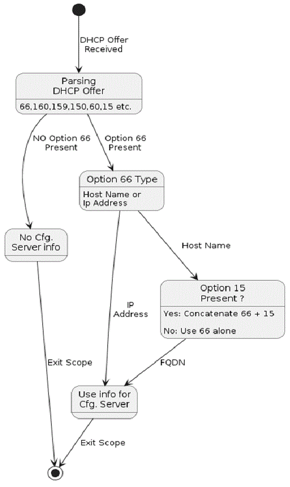
DHCP option 66 can provide either hostname or IP address of a TFTP server, or an entire Fully Qualified Domain Name (FQDN). If a domain name is required, this domain name can be provided separately through option 15. This allows for flexibility in network configurations, as the TFTP server and the domain used for DNS resolution do not necessarily need to be in the same domain.

For example, if you have a TFTP server with a FQDN of “tftpserver.example.com”, you caneither set option 66 to “tftpserver.example.com” or split it into option 66 with “tftpserver” and option 15 with “example.com”. The client device then appends the domain name from option 15 to the hostname from option 66 while making requests, resulting in “tftpserver.example.com”.

DHCP Option 60 Vendor ID: DHCP Option: (60) Vendor class identifier is an option to identify the product engaging DHCP conversation towards the DHCP server.

DHCP FQDN Functionality Flow Chart

The flowchart explains the following conditions for the FP to make use of the information and attempt to contact the configuration server.

  • Option 66 is an IP address. If the IP address of the configuration server is provided in option 66, option 15 is ignored. Only the IP address is used as the configurations server.

  • Option 66 is a hostname and not an IP address. Assuming the configuration server hostname is in option 66, the FP concatenates this with option 15 to form the FQDN of the TFTP server.

  • Option 66 is not an IP address, and there is no option 15. The resulting FQDN will be the Option 66 that merges with empty option 15.

Add Handsets to the Base Station

You need to configure the handsets on the base station so that they can connect and communicate.

You can add and register handsets one at a time, or you can set up multiple handsets.

  • Single handset setup: At the end of this procedure, the base station has the information about the handset set up, but the handset is not registered to the base station and able to make calls.

  • Multiple handset setup: At the end of this procedure, the base station is set up, but you need to complete user-specific configuration to assign the handset to the correct person.

You may find the Handset Configuration Parameters Worksheet helpful.

Before you begin

Connect to the base station web page as described in Sign in to the administration web page.

The base station needs to be connected to the network and the green LED lit.

Procedure


Step 1

Click Extensions.

Step 2

(Optional) Change the Access Code (AC).

We recommend that you change the AC to prevent users from deregistering the handset.

Step 3

Click Add extension.

Step 4

Set the Line name. Typically, this is the name of the user.

Step 5

For a new handset, set Terminal to New Terminal.

Step 6

Set the Extension field to the telephone number assigned to the user.

Step 7

Set the Authentication User Name field to the user ID assigned to the user.

Step 8

Set the Authentication Password field to the user's assigned password..

Step 9

Set the Display Name field to the name you want to be displayed on the handset screen.

Step 10

Set the Server field to the Server Alias you configured when you added the base station.

Step 11

Configure the remaining extension fields, as described in Add or Edit Extension Web Page Fields.

Step 12

Click Save.

Step 13

(Optional) Repeat steps 2 to 10 to add more handsets.


What to do next

Assign handsets to users

When you set up multiple handsets, you need to assign each handset to a specific user. Each user has a unique phone number and voicemail box, and may have different features. You can assign individual access code to each handset with the Terminal web page fields or in the configuration file (.xml). You can set the access code this way in the configuration file:
<Subscr_Dect_Ac_Code_x_>nnnn</Subscr_Dect_Ac_Code_x_>
Where, x is the handset number and nnnn is the access code.

If the access code is more than 4 digits, only the first 4-digits are accepted.

To assign the handset to the user, you assign the International Portable Equipment Identity (IPEI) number of the handset to the correctly configured extension. The IPEI number for the handset is located in these locations:

  • On the label of the box that contained the handset

  • Under the handset battery

You may find the Handset Configuration Parameters Worksheet helpful.

Before you begin

Connect to the base station web page as described in Sign in to the administration web page.

The base station needs to be connected to the network and the green LED lit.

The handsets need to be set up as described in Add Handsets to the Base Station.

Procedure


Step 1

Click Extensions.

Step 2

Click the link in the Extension Info column for the handset for a specific user.

The IPEI link shows the null IPEI number FFFFFFFFFF.

Step 3

In the Terminal page, set the IPEI field to the IPEI for the user's new handset.

Step 4

Set the AC field.

Step 5

(Optional) Configure the other fields, as described in Terminal Web Page Fields.

Step 6

Click Save.

Step 7

(Optional) Repeat steps 3 to 7 to set up more handsets.


What to do next

Start handset registration.

Start handset registration

After you have one or more handsets configured on the base station, you tell the base station to start the registration process. The base station waits to receive registration messages from the handsets to complete the communication loop.

You can register all the handsets at the same time or register them one by one.

Before you begin

Connect to the base station web page as described in Sign in to the administration web page.

The base station needs to be connected to the network and the green LED lit.

Procedure


Step 1

In the Extensions page, check the check boxes beside the new handsets to be registered.

Step 2

Click Register Terminal.

Step 3

Check the check boxes for the handsets in the Extension column.

Step 4

Click Start SIP Registration(s).


What to do next

Connect the handset to the base station

After you configure the handset to connect to the base station, it registers. You can make calls when the registration is complete.

If your users perform this procedure, then you need to give them the procedure and the access code.

Before you begin

Procedure


Step 1

Turn on the handset. See Turn on your handset.

Step 2

Press Menu .

Step 3

Select Connectivity > Register.

Step 4

Press Select.

Step 5

(Optional) Enter the access code in the AC field.

Step 6

Press Ok.


Turn on your handset

Procedure

Press and hold Power/End until the screen turns on.


Add a Repeater

If you have a 110 Single-Cell Base Station, you can extend coverage in your location with 110 Repeaters. You can have up to 6 repeaters.

If you have a 210 Multi-Cell Base Station, you can extend coverage in your location with 110 Repeaters. You can have up to 3 repeaters per base station.


Note


Do not connect the repeater to power until Step 6.

When you power on a new repeater, it tries to register with the base station, and this registration needs to happen within 5 minutes.


The repeater reboots at the end of its configuration. This is normal because it has set up encrypted communications. After the reboot, it is ready to use.

You can add a repeater in the Repeaters web page or in configuration file (.xml).

Before you begin

Connect to the base station web page as described in Sign in to the administration web page.

Procedure


Step 1

Click Repeaters.

Step 2

Click Add Repeater.

Step 3

Set the DECT sync mode field.

  • Manual: You need to manually assign parameters.
  • Local Automatic: The repeater detects the base signal and automatically configures.
  • Chaining Automatically: All base stations and repeaters send a RSSI report to the primary base station. The primary base station uses the report to create a new DECT synchronization tree with all the selected base stations and repeaters to use this setting.
In the configuration file(.xml), enter a string in this format:
<Repeater_Auto_Config_Mode_1_>n</Repeater_Auto_Config_Mode_1_>

Where, n is the value 0 (Manual), 1 (Local Automatic), or 2 (Chaining Automatically)

.

Step 4

For manual configuration, select a Repeater RPN from the dropdown menu.

Each repeater needs a unique RPN.

  • Single cell systems: The base is always RPN000. The first repeater is RPN01, the second RPN02, and so on.

  • Multicell systems: The base numbers increment by 4 (RPN00, RPN04, and so on). The first repeater for the first base station is RPN01, the second RPN02. The first repeater for the second base station is RPN05, the second RPN06.

Step 5

Click Save.

Step 6

Power on the repeater.

The repeater LED will flash green (two short flashes) to indicate registration mode. When registration completes, the repeater and base station reboot to set up encrypted communications.

If you powered on the repeater before you completed step 5 and the repeater LED is red, the repeater won't register. You must follow the information in Can't Set Up a Repeater - LED is Red to get the repeater into registration mode.


EDOS Profile and XML Parameters

The base station now allows to download complete XML config file from Cisco EDOS server. It handles EDOS in the following way:

  • When the base boots up and no configuration server is set, then configuration file is downloaded from the EDOS server.

  • When the base boots up and there is no DHCP options present on the network, Then the base will reach out to CDA (EDOS) and look for its configuration file. Then the base downloads it from the EDOS server:

    https://activate.cisco.com/software/edos/callhome/rc?id=$MAU:$SN:$PN&sw=$SWVER

After successful download, the configuration file is parsed as any other configuration file.

  • If there is no <profile_rule> set in the downloaded configuration file, then it will not store any server that provides the configuration file to the base station. In this situation, when the base restarts the EDOS config file will download again.

  • If there is a <profile_rule> set in the downloaded configuration file, then it is stored in the the base memory and the base reboots. This is the current behavior of the base.

When the download fails, the base tries downloading at retry intervals (in minutes) of 30, 60, 120, 240, 480, 960, 1440 (24h) 1440, 1440. If the retry reaches to 1440 minutes, then it will continue to try and download at every 1440 minutes until the base reboots. After the base reboots (normal reboot or factory default), the base will try and download from EDOS again when no configuration server is set or no server is received from a DHCP option.


Note


  • If a DHCP option such as 66, 160, 150 is present on the network, then the base will stop its process and never reaches out to CDA (EDOS).
  • If download from the server provided from the DHCP fails, the EDOS configuration will not download.
  • If there is no filename in the DHCP, then no address is stored in the Configuration Server Address (profile rule) on the base (server or filename). Hence, every time the base starts, it will first search for DBS-210-3PC.xml (DBS-110-3PC.xml for Dual cell) followed by $MA.cfg only if there is a server mentioned in the DHCP.

Change the Handset Information

You can configure common handset information like the access code, alarm information, shared lines, and the phone book.

Before you begin

Connect to the base station web page as described in Sign in to the administration web page.

The base station needs to be connected to the network and the green LED lit.

Procedure


Step 1

Click Extensions.

Step 2

In the IPEI column, click the link for the phone.

Step 3

Configure the terminal fields, as described in Terminal Web Page Fields.

Step 4

Click Save.


Change the Extension

You can configure each extension on the handset. Extension information includes the user's name and password, the phone number, voicemail, and some features.

Before you begin

Connect to the base station web page as described in Sign in to the administration web page.

The base station needs to be connected to the network and the green LED lit.

Procedure


Step 1

Click Extensions.

Step 2

In the Extension column, click the link for the phone.

Step 3

Configure the server fields, as described in Extensions Web Page Fields.

Step 4

Click Save.


Configure Language and Text Settings for a Handset

You can change the language and text settings in the language file (.xml) to update these settings in the handset. Define these elements in the language file (.xml) to change the settings:

  • CustomTexts: Define the attributes Locked to change the language and Version attribute to display the language pack version on the handset. If you set Locked to enabled, you can’t change the language on your handset.

  • Language: Define the attributes BaseLanguage for the current language, Name for the display, and CustomInput Language to change to another active language on the handset.

  • Text: Define the attribute ID for the name of the text identifier on the handset, Text for the original text in the Firmware, and CustomText with the new text to display on the handset. You can add only one CustomText attribute to each text element.

The base station converts this file an accepted format and sends the file to the handset. This file updates the settings in the handset. You must place the handset on the charging station for the update. When the update begins, you can view the status or errors on the Extensions or Syslog web page. After the update, restart the handset. The handset displays the language pack version on the Status screen, after the restart.

You can reset these settings in the base station or handsets if the update fails, reset to different settings or return to default settings. In the base station, you can erase the filename to reset to default settings or enter a new filename to replace with new settings.

For more information to reset the handset to default settings, see the section Reset Language and Text to Default in the Handset in Cisco IP DECT 6800 Series User Guide.

You can set the language file (.xml) in the Firmware Update web page or in the configuration file (.xml).

Before you begin

Connect to the base station web page as described in Sign in to the Administration Web Page.

Procedure


Step 1

Click Firmware Update.

Step 2

Enter the filename in the Language pack field for each handset.

In the configuration file (.xml), enter a string in this format:

<Language_Rule>https://www.server.com/path/[handsettype]_[name].xml</Language_Rule>

Where, [handsettype]_[name] is the handset type (example, 6825) with the language filename.

Step 3

Click Start/Save Update.

Accept the messages that display during the update.


What to do next

Confirm the language and the text displays on your handset.

Security

The system hardware has Manufacturing Installed Certificates (MIC) already installed. But you may want to increase the security of your system.

To increase security, you need custom certificates that have been generated by a Certificate Authority (CA).

You can also increase the media security. For more information, see Set Up the Media Security.

Set Up a Device Certificate and Key Pair

The base station uses the device identity certificate and key pair when the base station acts as a server, or when the server requires client SSL authentication.

Certificates can be installed on the system in the factory or by your service provider. You can also buy your own certificates. If you buy and install your own certificates, the certificates must be in DER encoded binary X.509 (.cer) format.

Before you begin

Connect to the base station web page as described in Sign in to the administration web page.

Obtain a custom certificate.

Procedure


Step 1

Click Security.

Step 2

In the Device Identify section, click Choose Files.

For information on field requirements, see Security Web Page Fields.

Step 3

Select the certificate and click OK.

Step 4

Click Load.

Step 5

Click Save.


Set Up a Trusted Server Certificate

The base station may need a trusted server certificate to validate a certificate chain.

Certificates can be installed on the system in the factory or by your service provider. You can also buy your own certificates. If you buy and install your own certificates, the certificates must be in DER encoded binary X.509 (.cer) format.

Before you begin

Connect to the base station web page as described in Sign in to the administration web page.

Obtain a custom certificate.

Procedure


Step 1

Click Security.

Step 2

In the Trusted Server Certificates section, click Choose File.

For information on field requirements, see Security Web Page Fields.

Step 3

Select the certificate and click OK.

Step 4

Click Load.

Step 5

Click Save.


Set Up a Trusted Root Certificate

The base station uses trusted root certificates from the server to authenticate the SSL handshake.

Certificates can be installed on the system in the factory or by your service provider. You can also buy your own certificates. If you buy and install your own certificates, the certificates must be in DER encoded binary X.509 (.cer) format.

Before you begin

Connect to the base station web page as described in Sign in to the administration web page.

Obtain a custom certificate.

Procedure


Step 1

Click Security.

Step 2

In the Trusted Root Certificates section, click Choose File.

For information on field requirements, see Security Web Page Fields.

Step 3

Select the certificate and click OK.

Step 4

Click Load.

Step 5

(Optional) Set the Use Only Optional Certificates field.

Step 6

Click Save.


Set Up the Media Security

The base station uses the media security to protect media sessions. You can enable the media security feature and use it only if the SIP transfer protocol is TLS or the NAPTR can choose TLS as the SIP transport. You can change the media protocol to RTP or SRTP. For information about the fields, see Servers Web Page Fields.

Configure the media security in the Servers web page or configuration file.

You configure the feature this way in the configuration file (.xml):

<MediaSec_Request_n_>enabled</MediaSec_Request_n_>
<MediasSec_Over_TLS_Only_n_>disabled</MedissSec_Over_TLS_Only_n_>

Where, n indicates the server number.

Before you begin

Connect to the base station web page as described in Sign in to the administration web page.

Procedure


Step 1

Click Servers.

Step 2

In the Media Security field, select Enabled.

Step 3

In the Media Security only for TLS field, select Enabled.

Step 4

In the Secure RTP field, select Auto.

Step 5

Click Save.


Configure On-Device Firewall

You can enable stateful firewall to control incoming network traffic for Cisco IP DECT 110 Single-Cell Base Station and Cisco IP DECT 210 Multi-Cell Base Station as outgoing traffic is considered as trusted. When the firewall is enabled, incoming traffic is blocked, and silently discarded by default on all listening ports (excludes Web server, SRTP, and the ports used for inter-base communication). When you configure the base station to unblock traffic for a specific port or range of ports, the base station does not block the traffic from the specifed port range. However, incoming traffic is always blocked on the ports which are not opened.

This feature disables incoming traffic on existing ports or services. The firewall unblocks normally blocked ports. The outgoing TCP connection or UDP flow unblocks the port for return and continued traffic. The port is kept unblocked although the flow is active. The port reverts to blocked state after an interval with no activity.

Before you begin

Connect to the base station web page as described in Sign in to the administration web page.

Procedure


Step 1

Click Security.

Step 2

In the Firewall section, set the fields Firewall, No ICMP Ping, No ICMP unreachable, No non-default TFTP, Trusted TCP port range, Trusted UDP port range. For information on field requirements, see the table Firewall Section Fields in Security Web Page Fields.

Step 3

Click Save.


Firewall Default Port Settings

The firewall is enabled by default with the settings in following table. Services listening on ports that are blocked by default, might not operate as expected, before firewall is configured with trusted port(s).

Table 2. Firewall Default Port Settings

Usage

Port

Protocol

Description

Blocked

DHCP/ DHCPv6

68 / 546

UDP

To be able to get IP address.

No

RTP / SRTP

Configurable start port and range: (Default: 16384:16424)

UDP

No

Sync

Based on chain-id Port range: 49200:50000

UDP

Inter-base data synchronization (Multicast or peer-to-peer)

No

SIP Configurable start port: (default: 5060) UDP

Only relevant when SIP configured for UDP.

In case each SIP extensions uses different port, the trusted port range will start from configured base port and next 1000 for DBS-210 / 30 for DBS-110.

No
Trel 10010:10011 UDP Inter-base communication No
Latency Stats 12285 UDP Inter-base latency statistic No
Web Server 80 / 443 TCP Web interface No
ICMP - ICMP Diagnostic network No
ARP - ARP Address resolution protocol No
PTP (IEEE1588)

Configurable event port: (default: 319)

General port: Event port +1 (default: 320)

UDP Radio LAN synchronization might be operational, even though the used ports are not trusted by firewall. This is due to the concept of trusting ports for outgoing traffic and keep it open for responses. However, it is still recommended to configure firewall to explicit trust the ports, if IEEE1588 LAN Sync is used instead of DECT Sync. Yes

PTT

Control port: 42000 RTP port: 52000

UDP

Push-to-talk requires at least two handsets has enabled the feature. Base station automatic starts the service, but firewall blocks incoming data until both ports are explicit trusted

Yes

Change the Web Page Administrator or User Password

We recommend that you change the administrator and user password when you set up the system.

You can change the administrator or user password in the Security web page or in the configuration file (.xml).

Change the password this way in the configuration file (.xml).
  • Administrator password:
    <Admin_Password>xxxxxxxx</Admin_Password>

    Where, xxxxxxxx is the new admin password.

  • User password:
    <User_Password>xxxxxxxx</User_Password>

    Where, xxxxxxxx is the new user password.

Before you begin

Connect to the base station web page as described in Sign in to the administration web page

Procedure


Step 1

Click Security.

Step 2

In the Password section, set the password fields.

For information on field requirements, see Security Web Page Fields.

Step 3

Click Save.


Set a Password Rule

You can define the minimum password length and restrict the use of ASCII characters in the password in the Security web page or the configuration file (.xml).

The default password length is 4 and maximum is 127.

You configure the feature this way in the configuration file (.xml):
<Web_Min_Pass_Len>4</Web_Min_Pass_Len>
<Web_Pass_Constraint_To_Ascii>0</ Web_Pass_Constraint_To_Ascii>

Before you begin

Connect to the base station web page as described in Sign in to the administration web page.

Procedure


Step 1

Click Security.

Step 2

In the Web password constraints section, set these fields:

  • Minimum length (min 1): Enter the value for the minimum password length.

  • Only ASCII characters: Select Yes to restrict the use of characters in the password.

Step 3

Click Save.


Set Up the Web Server for HTTP or HTTPS

To make your base station more secure, you can set it up to communicate with HTTPS only. The default is to allow HTTP or HTTPS.

Before you begin

Connect to the base station web page as described in Sign in to the administration web page

Procedure


Step 1

Click Security.

Step 2

In the Secure Web Server section, enable or disable the requirement for HTTPS.

For information on field requirements, see Security Web Page Fields.

Step 3

Click Save and Reboot.


Cisco Product Security Overview

This product contains cryptographic features and is subject to U.S. and local country laws that govern import, export, transfer, and use. Delivery of Cisco cryptographic products does not imply third-party authority to import, export, distribute, or use encryption. Importers, exporters, distributors, and users are responsible for compliance with U.S. and local country laws. By using this product, you agree to comply with applicable laws and regulations. If you are unable to comply with U.S. and local laws, return this product immediately.

Further information regarding U.S. export regulations can be found at https://www.bis.gov/ear.

Local Contacts Setup

You can manage contact lists for your users. For example, you might set up a contact list for all members of a team or department. You have these options:

  • Create a contact list on a handset, export it from the handset, and import it into another handset.

  • Create a contact list with a text editor and import it into another handset.


Note


When you import a contact list, it overwrites the existing contact list. If the user has created custom contacts, then these custom contacts are lost.


Import a Contact List

You can import a standard contact list to a handset. For example, you might set up a contact list for all members of a team or department.


Note


When you import a contact list, it overwrites the existing contact list. If the user has created custom contacts, then these custom contacts are lost.


Before you begin

You can export a contact list from a handset or you can create a contact list using a text editor, such as Notepad. Other programs may insert additional information that can't be parsed correctly. Set the file extension to .csv or .txt.

The list is created in comma separated value (CSV) format. Here is an example.

John Smith,+2345678901,+2345678901,,+2345678911
Ann Jones,+2345678902,+2345678902,,+2345678912
Fred Brown,+2345678903,+2345678903,,

The format of each line of the file is

<name>,<work number>,<mobile number>,<home number>,<other number>

Where:

  • <name> is the name of the user. The constraints to the name are:

    • Can be up to 23 characters long. Names longer than 23 characters are truncated.

    • Can't contain a comma (,).

    • Only uses the letters listed in Supported Characters.

  • <work number>,<mobile number>, <home number>,<other number> are the phone numbers. The constraints to each number are:

    • Can be left empty. There shouldn't be a space between two commas(,). For example, if the contact doesn't have a mobile number, the line becomes <name>,<work number>,,<home number>,<other number>

    • Can be up to 21 digits long (including +). If the number is longer than 21 digits, the entry is discarded with no warning.

    • Can only contain these characters: +0123456789

    • Can't be a SIP URI.

Procedure


Step 1

Click Extensions.

Step 2

In the Extension column, click the link for the phone.

Step 3

In the Import Local Phonebook area, click Choose File.

Step 4

Browse to the file, select it, and click OK.

Step 5

Click Load.

Step 6

Click OK.


Export a Contact List

You can export the local contacts list from a handset.

You may find it useful to create a contact list on a handset, export it, then import it into other handsets.

Procedure


Step 1

Click Extensions.

Step 2

In the Extension column, click the link for the phone.

Step 3

In the Export Local Phonebook area, click Export.

Step 4

Choose a location to save the file and click OK.


Central Directory Setup

A central directory is a directory on the handset that allows your users to look up and call people easily. The type of directory you use depends on a number of factors.

  • If you administer a small network, you can do any of the following:
    • Create a local directory as a text file and upload it to the base station.

    • Create a local directory text file and save in the folder Directory in the server. The base station locates the file in this directory when it uses the http protocol.

  • If your organization already has a Lightweight Directory Access Protocol (LDAP) phone directory (for example, for desk phones), you can configure the same directory on the base station.

Set Up a Text Central Directory

Before you begin

You create a text file for the directory. The text file is in the following format:

<name>,<number>

Where:

  • <name> is the name of the user. The constraints to the name are:

    • Can be up to 23 characters long. Names longer than 23 characters are truncated.

    • Can't contain a comma (,).

    • Only uses these characters:

      • A–Z

      • a–z

      • 0–9

      • -

      • '

  • <number> is the phone number. The constraints to the number are:

    • Can be up to 21 digits long (including +). If the number is longer than 21 digits, the entry is discarded with no warning.

    • Can only contain these characters: +0123456789

    • Can't be a SIP URI.


Note


Don't put a space between the comma and the phone number, or the entry is discarded.


Here is a sample txt file.

John Smith,+2345678901
Ann Jones,+2345678902
Fred Brown,+2345678903

The file size must be less than 100 Kb.

You create this list with a text editor such as Notepad. Other programs may insert additional information that can't be parsed correctly. Set the file extension to .csv or .txt.


Note


If you have a directory uploaded and then upload a new directory, the new directory overwrites the old directory.


Connect to the base station web page as described in Sign in to the administration web page.

Procedure


Step 1

Click Central Directory.

Step 2

Set the Location field to Local.

Step 3

Click Save.

Step 4

Locate and import the CSV file. For more information, see "Local Directory Fields" and "Import Central Directory Section Fields" tables in Central Directory Web Page Fields.

Step 5

Click Save.


Set Up an LDAP Central Directory

Before you begin

You need the information about the LDAP directory.

Connect to the base station web page as described in Sign in to the administration web page.

Procedure


Step 1

Click Central Directory

Step 2

Set the Location field to LDAP Server.

Step 3

Click Save.

Step 4

Configure the LDAP fields, as described in the "LDAP Central Directory Fields" and "LDAP Central Directory: Handset Identity Section Fields" tables in Central Directory Web Page Fields.

Step 5

Click Save.


Set Up an XSI Central Directory


Note


This type is currently not supported.


You can create an XSI file with the directory entries and then upload the XSI file to the base station.

You create this file with a text editor such as Notepad. Other programs may insert additional information that can't be parsed correctly. Set the file extension to .xsi.


Note


If you have a directory uploaded and then upload a new directory, the new directory overwrites the old directory.


Before you begin

You need to create an XSI directory file. The requirements are:

  • The file must have the .xsi file extension.

  • Names longer than 23 characters will be truncated to 23 characters.

  • Only uses the letters listed in Supported Characters.

  • Phone numbers can be up to 21 digits long, including the plus (+).

  • Phone numbers can only contain +0123456789 characters.

  • Phone numbers can't be a SIP URI.

  • Each <DirectoryEntry> tag needs a <Name> and <Telephone> tag. The Telephone tag identifies the main telephone number.

The schema for the XSI file is:

<IPPhoneDirectory>
<DirectoryEntry>
<Name>x</Name>
<Telephone>x</Telephone>
<Office>x</Office>
<Mobile>x</Mobile>
<Fax>x</Fax>
</DirectoryEntry>
</IPPhoneDirectory>

You add as many <DirectoryEntry> tags as you need. Remember to close the tags (for example, </DirectoryEntry>).

Here is a sample XSI file.

<IPPhoneDirectory>
<DirectoryEntry>
<Name>John Smith</Name>
<Telephone>1001</Telephone>
<Office>+2345678901</Office>
<Mobile>+2345678901</Mobile>
<Fax>+2345678911</Fax>
</DirectoryEntry>
<DirectoryEntry>
<Name>Ann Jones</Name>
<Telephone>1002</Telephone>
<Office>+2345678902</Office>
<Mobile>+2345678902</Mobile>
<Fax>+2345678912</Fax>
</DirectoryEntry>
<DirectoryEntry>
<Name>Fred Brown</Name>
<Telephone>1003</Telephone>
<Office>+2345678903</Office>
<Mobile>+2345678903</Mobile>
</DirectoryEntry>
</IPPhoneDirectory>

Connect to the base station web page as described in Sign in to the administration web page.

Procedure


Step 1

Click Central Directory

Step 2

Set the Location field to Broadsoft XSI Server.

Step 3

Click Save.

Step 4

Configure the XSI fields, as described in the "XSI Central Directory Fields" and "XSI Central Directory:Directory Name Fields" tables in Central Directory Web Page Fields.

Step 5

Click Save.


Parameters for XSI Phone Service

Table 3. Parameters for XSI Phone Service

Parameter

Description

Central Directory Location

Identifies the type of central directory:

  • Broadsoft XSI Server—Indicates that an XSI central directory is used (for example, a BroadSoft directory). See "XSI Central Directory" below.

  • Local—Indicates that an imported comma separated value (CSV) file is to be used. See "Local Directory" below.

  • LDAP Server—Indicates that an LDAP directory is used. See "LDAP Directory" below.

Server

Identifies the Broadsoft XSI Server.

Enterprise

Allows you to change the Enterprise string to another label. For example, if you set this field to "Company", the handset displays "Company" instead of "Enterprise".

EnterpriseCommon

Allows you to change the EnterpriseCommon string to another label.

Group

Allows you to change the Group string to another label. For example, if you set this field to "Department", the handset displays "Department" instead of "Group".

GroupCommon

Allows you to change the GroupCommon string to another label.

Personal

Allows you to change the Personal string to another label. For example, if you set this field to "Home", the handset displays "Home" instead of "Personal".

Feature Setup

You may need to change some of the features that impact the user experience. Make sure that you tell your users if you change any of these features.

Set Up Management Settings

The Management page controls some internal system features and some features that impact users.

  • Settings area: controls some communication requirements and features.

  • Configuration area: controls how the base and handset handle configuration changes.

  • Text Messaging area: controls the ability for users to send and receive text messages. For more information, see Configure Text Messaging.

  • Syslog/SIP Log area: controls the storage of system messages and other information.

  • Emergency Numbers: controls the emergency numbers for users. For more information, see Configure Emergency Numbers.

Before you begin

Connect to the base station web page as described in Sign in to the administration web page

Procedure


Step 1

Click Management.

Step 2

Configure the Settings, Configuration, and Syslog/SIP Log fields, as described in the Settings table in Management Web Page Fields.

At minimum, you must configure this field:

  • Emergency Numbers

Step 3

Do one of these actions:

  • If you changed the VLAN field, click Save and Reboot.
  • For all other changes, click Save.

Configure Text Messaging

You may want to change the settings in the Text Messaging area in the Management web page. These fields control the ability of the handset to send and receive text messages. By default, text messages are disabled.

After being enabled, you can set up the system to allow messages only within your system or to allow messages to and from other systems.


Note


If you enable text messaging, make sure that you tell your users.


Before you begin

Connect to the base station web page as described in Sign in to the administration web page

Procedure


Step 1

Click Management.

Step 2

Configure the text message fields, as described in the Text Messaging table in Management Web Page Fields.

Step 3

Click Save.


Configure Paging

You can configure a paging group to page a group of handsets. You send a page to a group of handsets in the same network.

You can add a handset to up to three paging groups. Each paging group has a unique multicast port and number. The phones within a paging group must subscribe to the same multicast IP address, port, and multicast number.

You configure the priority for the incoming page from a specific group. The priority level ranges between 0 and 3. The priority level indicates:

  • 0: The incoming page places the active call on hold. The call resumes after the page is played.

  • 1: The incoming page and the active call play at the same time.

  • 2: The incoming page alerts with a tone. The paging plays when the active call is put on hold or the call ends.

  • 3: The incoming page doesn’t alert during an active call.

When multiple paging sessions occur, they are answered in chronological order. The active page must end to answer the next page. When do not disturb (DND) is enabled, the phone ignores incoming page.

The audio codec is set to G.711u.

Before you begin

  • Make sure that all the handsets in a paging group are in the same multicast network.

  • Access the phone administration web page.

Procedure


Step 1

Click Management.

Step 2

In the Multiple Paging Group Parameters section, set values for Group (n) Paging Script fields.

Enter a string to configure the phone to listen and initiate multicast paging. Each string can have a maximum length of 128 characters. You can add a phone to up to 3 paging groups. Enter the script in this format:
pggrp:multicast-address:port;[name=xxxx;]num=yyy;[listen={yes|no}]];pri=n

Where,

  • multicast-address—Indicates the multicast IP address the base stations listen and receive the pages.

  • port—Indicates the port to page. You use different ports for each paging group. Port must be between 0 and 65534, and have an equal value.

  • name=xxxx (optional)—Indicates the name of the paging group. The maximum length of the name is 35 characters.

  • num=yyy—Indicates a unique number to dial to access the paging group. The number is 3 or 4 digits.

  • listen={yes|no}—Indicates whether the phone listens on the page group. Only the first two enabled groups can listen. If the field isn't defined, the default value is no.

  • pri=n—Indicates the priority level of the paging. Priority level ranges 0–3.

For example:

pggrp=224.168.168.168:34560;name=All;num=500;listen=yes;pri=0

You can configure this parameter with configuration XML file (cfg.xml) by entering a string in this format:

<Group_Paging_Script_1_>pggrp=224.168.168.169:34560;name=All;num=500;listen=yes;pri=0</Group_Paging_Script_1_>

Step 3

Click Save.


Change Star Codes

The base station is set up with a series of star codes. Star codes enable users to access some functions quickly.

The Cisco IP DECT 6800 Series User Guide contains a list of the standard star codes.


Note


If you change a star code, make sure that you tell your users about the changes.


Before you begin

Connect to the base station web page as described in Sign in to the administration web page

Procedure


Step 1

Click Star Codes.

Step 2

Change the star code fields, as described in Star Codes Web Page Fields.

Step 3

Click Save.


Change Call Progress Tones

The base station is set up with a series of call progress tones. Call progress tones are tones that you hear during call setup and progression.

The default call progress tones depend on the country and region you set up for the base station. You can change the tones from the default values.

Before you begin

Connect to the base station web page as described in Sign in to the administration web page

Procedure


Step 1

Click Call Progress Tones.

Step 2

Configure the fields, as described in Call Progress Tones Web Page Fields.

Step 3

Click Save.


Set Up Call Quality Statistics to Call Server

You can send the call quality statistics to call control system after the call ends. The statistics is sent from the RTP media unit to the SIP control unit after each call ends in a Multicell system. You can view the statistics log in the SIP Log web page.

You enable the data collection with the Servers web page or in the configuration file (.xml).

Where, n is the server number.

Before you begin

Connect to the base station web page as described in Sign in to the administration web page.

Procedure


Step 1

Click Servers.

Step 2

Set Call Statistics in SIP to Enabled.

Enable the call statistics this way in the configuration file (.xml):
<Call_Statistics_In_SIP_n_>Yes</Call_Statistics_In_SIP_n_>

Step 3

Click Save.


Configure Alarms

You can set up the handsets to raise an alarm when the Emergency button on the top of the 6825 Handset or 6825 Ruggedized Handset is pressed.

Note


The 6823 Handset doesn't have an Emergency button.


Before you begin

Connect to the base station web page as described in Sign in to the administration web page.

You can configure an alarm server in the Management Settings page. See Set Up Management Settings and Management Web Page Fields. If you don't configure an alarm server, you can make calls to the defined number.

Procedure


Step 1

Click Alarm.

Step 2

Configure the alarm fields, as described in Alarm Web Page Fields.

Step 3

Click Save.


What to do next

After you set up the alarm profile alias, go to Change the Handset Information and assign the alarms to each handset that requires the alarm. You need to set the Alarm Profile and configure the Alarm Line and Alarm Number fields. After you set up alarms on a handset, you need to reboot the handset.

Configure the Location Server for Emergency Calls

You can define the HTTP Enabled Location Delivery (HELD) company ID, primary, and secondary server in the base station to receive the location information for emergency calls. The location information is sent to the Public Safety Answering Point (PSAP). The handset has a retry timeout of 120 seconds to receive the valid location token.

You can enter the HELD company ID and server details in the base station’s Management web page or configuration file (.xml).

Configure the notification fields this way in the configuration file (.xml).

<Held_Company_Id>n</Held_Company_Id>, where n is the HELD company account ID.

<Held_Token_Srv1>n</Held_Token_Srv1>, where n is the primary server address.

<Held_Token_Srv2>n</Held_Token_Srv2>, where n is the secondary server address.

Before you begin

  • Connect to the base station web page as described in Sign in to the Administration Web Page.

  • Ensure that the network supports LLDP or CDP protocols and configured on the HELD (RedSky) server. If the network uses CDP, configure the advertisements between 5–900 seconds to get the valid token.

  • Ensure that the location information server database is mapped to civic addresses.

  • Ensure that both the configured dial plans and emergency numbers can exist.

  • Set the company ID as a server setting and not a global setting. The extensions connected to a defined server refers to specific company ID during an emergency call.

Procedure


Step 1

Click Management.

Step 2

Set the fields in the HELD (RedSky) section as described in Management Web Page Fields.

Step 3

Click Save.


Configure Emergency Numbers

You may want to change the settings in the Emergency Numbers table in the Management web page. These fields control the numbers that are associated with emergency calls.

Make sure that your users are familiar with the emergency numbers. Your users can dial these numbers even if the keypad is locked.

Before you begin

Connect to the base station web page as described in Sign in to the administration web page

Procedure


Step 1

Click Management.

Step 2

Configure the emergency numbers, as described in the Emergency Numbers table in Management Web Page Fields.

Step 3

Click Save.


Add or Edit Local Call Groups

You can add or edit a local call group and associate multiple handsets to a group. You register the extension to the SIP server. The registered handsets in the group can receive incoming calls within the group, make new calls, transfer calls, and make three-way conference calls.

You can create up to 32 call groups for 210 Multi-Cell Base Station and 10 call groups for 110 Single-Cell Base Station.

You add or edit the call group with the base station's Local Call Groups web page or in the configuration file (.xml).

You can add or edit a call group and configure the handset extension in the configuration file (.xml) by entering a string in this format:
<Call_Group_Sip_Account_n_>x</Call_Group_Sip_Account_n_>

Where, n is the call group ID and x is the extension.

Before you begin

Connect to the base station web page as described in Sign in to the Administration Web Page.

Procedure


Step 1

Click Local Call Groups.

The Local Call Groups page displays the list of the call groups.

Step 2

Click Add Call Group.

The Local Call Groups page displays.

Step 3

Set the fields as described in Local Call Groups.

Step 4

Click Save.


What to do next

Configure Handsets to the Call Group

Configure Handsets to the Call Group

After you add or edit a call group, you configure the handset to the group. You can configure the handsets to none, one, or up to 32 call groups with bit mapping. The following are the bit mapping details:
  • 0x0—No Call Group is associated.

  • 0x1—Call Group 1 is associated with this Terminal (bitmap 1, decimal 1).

  • 0x3—Call Groups 1 and 2 are associated with this Terminal (bitmap 11, decimal 3).

  • 0x6—Call Groups 2 and 3 are associated with this Terminal (bitmap 110, decimal 6).

  • 0x20080001—Call Groups 1, 20 and 30 are associated with this terminal (bitmap 00100000000010000000000000000001, decimal 537395201).

You configure the handset to the call group with the base station's Terminal web page or in the configuration file (.xml).

Before you begin

Connect to the base station web page as described in Sign in to the Administration Web Page.

Ensure that the handset is registered to the base station.

Procedure

Step 1

Click Terminal.

Step 2

Enter the group number as the bit map number in the Call Group(s) field.

You can also configure this parameter in the configuration file (.xml) by entering a string in this format:
<Subcsr_Call_Group_Subscribed_>x</Subcsr_Call_Group_Subscribed_>

Where, x is the call group bit map number.

Step 3

Click Save.


What to do next

Configure Handset Intercom Function

Configure Handset Intercom Function

You can enable the intercom feature for the handset in a call group. The intercom function allows the handsets in the group to make new calls, calls within the group, transfer calls to the handsets within the group, and make three-way conference calls.

On 210 Multi-Cell Base Station, there is no call group.

You can set up the intercom with the base station's Terminal web page or in the configuration file (.xml).

Before you begin

Connect to the base station web page as described in Sign in to the Administration Web Page.

Ensure that the extension registers successfully with the SIP server.

Procedure

Step 1

Click Extensions.

Step 2

Click the link in the Extension Info column for the handset for a specific user.

The Terminal page displays.

Step 3

Select the option Enabled in the Intercom field.

You can also configure this parameter in the configuration file (.xml) by entering a string in this format:
<Subscr_Intercom_Enabled_>x</Subscr_Intercom_Enabled_>

Where, x is the value to enable the intercom feature.

Step 4

Click Save.


Temporary Handset Addition to the Base Station

You can register a handset temporarily to the base station in promiscuous mode. The base station can be in promiscuous mode when it’s factory reset. The promiscuous mode is active for 255 minutes when enabled from the Management web page or configuration file (.xml), or 5 minutes when you press the base station Reset button. You can add the unregistered handsets to the base station and update the handsets.

The base station downloads the configuration file from the CDA or DHCP server to update the handsets. If the server requests authorization, you enter the username and password with the handset. If the base station doesn't have the <profile_rule> set in the configuration file, the CDA server requests the short activation code that you enter with your handset.

The handsets deregister when the promiscuous mode times out. If any handset update is in progress, the timer is reset.

You can enable the promiscuous mode in these ways:

Turn On Promiscuous Mode from the Firmware

You can set up promiscuous mode to enable temporary handset registration. When the base station is in promiscuous mode, the LED blinks in this order: red, amber, and green. The base station is in promiscuous mode for 255 minutes. You can register up to 30 handsets to the base station in this mode.

You set the mode this way in the configuration file (.xml):
<Promiscuous_mode>n</Promiscuous_mode>

Where, n is the time in minutes to enable the mode.

Before you begin

Connect to the base station web page as described in Sign in to the administration web page

Procedure

Step 1

Click Management.

Step 2

Configure Enable in (min) to indicate the number of minutes until promiscuous mode starts.

The Promiscuous mode timeout in field displays the number of minutes until promiscuous mode ends. Refresh the page to view the remaining time.

For more information, see the Promiscuous Mode table in Management Web Page Fields

Step 3

Click Save.


What to do next

Turn On Promiscuous Mode with the Base Station Reset Button

You enable promiscuous mode manually with the Reset button on the base station. If the option Promiscuous_button_enabled in the configuration file (.xml) is set to No, press the button for 15 seconds to reset the base station to the factory defaults and then enable the promiscuous mode. When you enable promiscuous mode, the base station LED flashes from red to amber in 2 seconds and then to green in 6 seconds. The base station is in promiscuous mode for 5 minutes.

Before you begin

Locate the Reset button on the bottom edge of the base station.

Procedure

Press and hold the Reset button for 6 seconds.


What to do next

Add a Second Line to a Handset

You can add another line to a handset.

Procedure


Step 1

Click Extensions.

Step 2

Identify the index number in the left column for the handset.

Step 3

Click Add extension.

Step 4

Set the Line name.

Give the line a different name from other lines to avoid confusion.

Step 5

In the Terminal field, select the handset for the second extension.

For example, if you are adding the line to the handset with index 2 from step 2, then select Terminal Idx 2.

Step 6

Set the Extension field to the telephone number assigned to the user.

Step 7

Set the Authentication User Name field to the user ID assigned to the user.

Step 8

Set the Authentication Password field to the user's assigned password..

Step 9

Set the Display Name field to the name you want to be displayed on the handset screen.

Step 10

Set the Server field to the Server Alias you configured when you added the base station.

Step 11

Configure the remaining extension fields, as described in Add or Edit Extension Web Page Fields.

Step 12

Click Save.

Step 13

In the Extensions page, check the associated VoIP Idx box.

Step 14

Click Start SIP Registration(s).

Step 15

Turn the handset off, then back on again.

Step 16

Start to enter a number in the handset, and press Line.

Step 17

Verify that the new extension is listed.

Note


For the 6823 Handset, the center softkey can still be used to change the line (similar to the 6825 Handset), but it is not displayed on the screen due to space limitations.


What to do next

If this extension is to be shared, see Share a Line Between Handsets

Share a Line Between Handsets

You can set up a line to be available on two or more handsets.

On the handset, the shared line displays in the line list when the user makes a call. The user also sees an icon immediately below the handset header row. The icon displays the status of the shared line.

Procedure


Step 1

Add the same extension to each handset. See Add a Second Line to a Handset.

For example:

  • Configure the extension to Terminal Idx 1 and register it.

  • Configure the extension to Terminal Idx 2 and register it.

Step 2

In the Extensions page, click the handset link (IPEI number) for the first handset that will share the extension.

Step 3

In the Shared Call Appearance Settings, set the Idx to the extension to be shared.

Step 4

Click Save.

Step 5

Repeat steps 2-4 for the second handset to share the number.


Modification to Handset Settings

You can update alarm, various settings, and connectivity for a handset when the handset is SIP registered to a base station. You can also update the settings at once for multiple handsets in a system.

There are various options to update settings on a handset. You can download the handset settings configuration file directly from the server for example, via a browser. The server may request authentication to download the file. Once downloaded, you can do either of the following:

  • Upload the file in the handset section of the base station on the Configuration page.

  • Send a SIP NOTIFY event from the server to the base to update the handset settings.

For more details, see Configure the Handset Server and Update Handset Settings.

Configure the Handset Server

You can define the server, protocol, and credentials to download the handset settings configuration file.

You configure server in the base station's Management web page or in the configuration file (.xml). The server may request login credentials to download the file.

Logs for the download is available in the Syslog web page.

If configuring via XML, configure the server in the base station the following way in the configuration file (.xml):

  • <Hs_Config_Server>n </Hs_Config_Server>, where n is the server address to the file. If the protocol isn't specified in the URL, TFTP is used.

  • <Hs_Config_Protocol>n</Hs_Config_Protocol>, where n is the protocol.

  • <Hs_Config_Server_Username>n</Hs_Config_Server_Username >, where n is the username to access the server.

  • <Hs_Config_Server_Password>n</Hs_Config_Server_Password>, where n is the password to access the server.

Before you begin: Connect to the base station web page as described in Sign in to the Administration Web Page.

Procedure

Step 1

Click Management.

Step 2

Configure the fields in the section Configuration -handset (retrieved on SIP NOTIFY request) as described in Management Web Page Fields

Step 3

Click Save.


What to do next

Update Handset Settings

Update Handset Settings

You use the handset settings configuration that you downloaded to update the handset settings. This file can update one handset or multiple handsets in a system.

You can update the handset settings either by uploading the handset settings configuration file in the base station's Configuration web page or by sending a SIP notification event Event:check-sync-handset;hs=all or Event:check-sync-handset;hs=1,3,5,900,30 to the server. The handset must be SIP registered to a base station and power must be on to update the settings.

Example: hs=all means all registered handsets and hs=1,3,5,900,30 means handset indexes 1,3,5,900 and 30. A maximum of 10 handset indexes can be defined.

You can view the update details in the handset's Settings menu or the base station's Terminal web page. If a base station or multiple base stations in a system restarts, the update details aren't available.


Note


To know more about XML tags description used for handset settings, see XML Tags for Handset Settings section in XML Reference Guide for Cisco IP DECT 6800 Series.


The base station attempts 3 times to update the handsets. If all the attempts fail, the handset doesn’t update the settings and the message saves in the syslog.

Before you begin:

  • Connect to the base station web page as described in Sign in to the Administration Web Page.

  • Ensure that the handset or handsets power is on.

  • Ensure that the handset or handsets in a system is SIP registered to the base station.

Procedure

Step 1

Click Configuration.

Step 2

Click Choose File in the Load Configuration field to upload the handset configuration file.

Step 3

Click Load.


Dial Plan

Dial Plan Overview

Dial plans determine how digits are interpreted and transmitted. They also determine if the number you dial is accepted or rejected. You can use a dial plan to facilitate dialing or block certain types of calls such as long distance or international.

Use the base station's Dial Plans web page or the configuration file (.xml) to configure dial plans.

This section includes information about dial plans, and procedures to configure the dial plans.

The Cisco IP DECT Phone has various degrees of dial plans and process the digits sequence.

When you press the speaker button on the handset, the following sequence begins:

  1. The base station begins to collect the dialed digits. The interdigit timer starts to track the time that elapses between digits.

  2. If the interdigit timer value is reached, or if another terminating event occurs, the base station compares the dialed digits with the dial plan.

Digit Sequences

A dial plan contains a series of digit sequences, separated by the | character. The entire collection of sequences is enclosed within parentheses. Each digit sequence within the dial plan consists of a series of elements that are individually matched to the keys that you press on the handset.

White space is ignored, but can be used for readability.

Digit Sequence

Function

0 1 2 3 4 5 6 7 8 9 * #+

Characters that represent a key that you must press on the handset.

x

Any key from 0-9 on the handset keypad.

[sequence]

Characters within square brackets create a list of accepted key presses. You can press any one of the keys in the list.

A numeric range, for example, [2-9] allows you to press any one digit from 2 through 9.

A numeric range can include other characters. For example, [35-8*] which allows you to press 3, 5, 6, 7, 8, or *.

. 
(period)

A period indicates element repetition. The dial plan accepts 0 or more entries of the digit. For example, 01. allows you to enter 0, 01, 011, 0111, and so forth.

<dialed:substituted>

This format indicates that certain dialed digits are replaced by the substituted characters when the sequence is transmitted. The dialed digits can be zero to 9. For example:


<8:1650>xxxxxxx

When you press 8 followed by a seven-digit number, the system automatically replaces the dialed 8 with the sequence 1650. If you dial 85550112, the system transmits 16505550112.

If the dialed parameter is empty and there is a value in the substituted field, no digits are replaced and the substituted value is always attached to the transmitted string. For example:


<:1>xxxxxxxxxx

When you dial 9725550112 on your handset, the number 1 is added at the beginning of the sequence; the system transmits 19725550112.

! 
(exclamation point)

Prohibits a dial sequence pattern. For example:


1900xxxxxxx!

Rejects any 11-digit sequence that begins with 1900.

*xx

Allows to enter a 2-digit star code.

S0 or L0

For Interdigit Timer Master Override, enter S0 to reduce the short interdigit timer to 0 seconds, or enter L0 to reduce the long interdigit timer to 0 seconds.

Digit Sequence Examples

The following examples show digit sequences that you can enter in a dial plan.

In a complete dial plan entry, sequences are separated by a pipe character (|), and the entire set of sequences is enclosed within parentheses:


( [1-8]xx | 9, xxxxxxx | 9, <:1>[2-9]xxxxxxxxx | 8, <:1212>xxxxxxx | 9, 1 [2-9] xxxxxxxxx | 9, 1 900 xxxxxxx ! | 9, 011xxxxxx. | 0 | [49]11 )
  • Extensions on your system:
    
    ( [1-8]xx | 9, xxxxxxx | 9, <:1>[2-9]xxxxxxxxx | 8, <:1212>xxxxxxx | 9, 1 [2-9] xxxxxxxxx | 9, 1 900 xxxxxxx ! | 9, 011xxxxxx. | 0 | [49]11 )
    

    [1-8]xx Allows to dial any three-digit number that starts with the digits 1 to 8. If your system uses four-digit extensions, enter the following string: [1-8]xxx

  • Local dialing with seven-digit number:
    
    ( [1-8]xx | 9, xxxxxxx | 9, <:1>[2-9]xxxxxxxxx | 8, <:1212>xxxxxxx | 9, 1 [2-9] xxxxxxxxx | 9, 1 900 xxxxxxx ! | 9, 011xxxxxx. | 0 | [49]111)
    

    9, xxxxxxx After you press 9, you can enter any seven-digit number, as in a local call.

  • Local dialing with 3-digit area code and a 7-digit local number:
    
    ( [1-8]xx | 9, xxxxxxx | 9, <:1>[2-9]xxxxxxxxx | 8, <:1212>xxxxxxx | 9, 1 [2-9] xxxxxxxxx | 9, 1 900 xxxxxxx ! | 9, 011xxxxxx. | 0 | [49]11 )
    

    9, [2-9]xxxxxxxxx This example is useful where a local area code is required. After you press 9, you must enter a 10-digit number that begins with a digit 2 through 9. The system automatically inserts the 1 prefix before it transmits the number to the carrier.

  • Local dialing with an automatically inserted 3-digit area code:
    
     ( [1-8]xx | 9, xxxxxxx | 9, <:1>[2-9]xxxxxxxxx | 8, <:1212>xxxxxxx | 9, 1 [2-9] xxxxxxxxx | 9, 1 900 xxxxxxx ! | 9, 011xxxxxx. | 0 | [49]11 )
    

    8, xxxxxxx This example is useful where a local area code is required by the carrier but most calls go to one area code. After you press 8, you can enter any seven-digit number. The system automatically inserts the 1 prefix and the 212 area code before it transmits the number to the carrier.

  • U.S. long-distance dialing:
    
     ( [1-8]xx | 9, xxxxxxx | 9, <:1>[2-9]xxxxxxxxx | 8, <:1212>xxxxxxx | 9, 1 [2-9] xxxxxxxxx | 9, 1 900 xxxxxxx ! | 9, 011xxxxxx. | 0 | [49]11 )
    

    9, 1 [2-9] xxxxxxxxx After you press 9, you can enter any 11-digit number that starts with 1 and is followed by a digit 2 through 9.

  • Blocked number:
    
     ( [1-8]xx | 9, xxxxxxx | 9, <:1>[2-9]xxxxxxxxx | 8, <:1212>xxxxxxx | 9, 1 [2-9] xxxxxxxxx | 9, 1 900 xxxxxxx ! | 9, 011xxxxxx. | 0 | [49]11 )
    

    9, 1 900 xxxxxxx ! This digit sequence prevents from dialing numbers that are associated with high tolls or inappropriate content, such as 1-900 numbers in the U.S. After you press 9, if you enter a 11-digit number that starts with the digits 1900, the call is rejected.

  • U.S. international dialing:
    
     ( [1-8]xx | 9, xxxxxxx | 9, <:1>[2-9]xxxxxxxxx | 8, <:1212>xxxxxxx | 9, 1 [2-9] xxxxxxxxx | 9, 1 900 xxxxxxx ! | 9, 011xxxxxx. | 0 | [49]11 )
    

    9, 011xxxxxx After you press 9, you can enter any number that starts with 011 for an international call from the U.S.

  • Informational numbers:
    
     ( [1-8]xx | 9, xxxxxxx | 9, <:1>[2-9]xxxxxxxxx | 8, <:1212>xxxxxxx | 9, 1 [2-9] xxxxxxxxx | 9, 1 900 xxxxxxx ! | 9, 011xxxxxx. | 0 | [49]11 )
    

    0 | [49]11 This example includes two-digit sequences, separated by the pipe character. The first sequence allows you to dial 0 for an operator. The second sequence allows you to enter 411 for local information or 911 for emergency services.

Acceptance and Transmission of the Dialed Digits

When you dial a series of digits, each sequence in the dial plan is tested as a possible match. The matching sequences form a set of candidate digit sequences. When you enter more digits, the set of candidates diminish until only one or none is valid. When a terminating event occurs, the server either accepts the dialed sequence and initiates a call, or else rejects the sequence as invalid. You hear the reorder (fast busy) tone if the dialed sequence is invalid.

The following table explains how terminating events are processed.

Terminating Event

Processing

Dialed digits have not matched any sequence in the dial plan.

Example:

Dial plan: (xx)

Digits: 123 - Rejected

The number is rejected.

Pressing hook off/call and dialed digits partially matches one sequence in the dial plan.

Example:

Dial plan: (xx)

Digits: 1 – Allowed

Digits: 12 – Allowed

Digits: *3 - Rejected

If the dial plan allows the partial sequence, the number is accepted and transmitted according to the dial plan.

Dialed digits exactly match one sequence in the dial plan.

Example:

Dial plan: (xx)

Digits: 12 - Allowed

If the dial plan allows the sequence, the number is accepted and is transmitted according to the dial plan.

If the dial plan blocks the sequence, the number is rejected.

A timeout occurs.

The number is rejected if the dialed digits are not matched to a digit sequence in the dial plan within the specified time.

The Interdigit Long Timer applies when the dialed digits do not match any digit sequence in the dial plan. The default time is 10 seconds.

The Interdigit Short Timer applies when the dialed digits match one or more candidate sequences in the dial plan. The default time is three seconds.

You press the # key hook off.

If # is in the dial plan, it is accepted as an input. Otherwise, the key is used as a hook off.

If the sequence is complete and is allowed by the dial plan, the number is accepted and is transmitted according to the dial plan.

If the sequence is incomplete or is blocked by the dial plan, the number is rejected.

Interdigit Long Timer (Incomplete Entry Timer)

The Interdigit Long Timer measures the interval between dialed digits. It applies until the dialed digits don't match any digit sequences in the dial plan. Unless you enter another digit within the specified number of seconds, the entry is evaluated. If the entry is valid, the call proceeds. If the entry is invalid, the call is rejected.

Default: 10 seconds

Syntax for the Interdigit Long Timer

SYNTAX: L:s, (dial plan)

  • s: The number of seconds. If a number isn't entered after L:, the default timer is 10 seconds. When the timer is set to 0 seconds, the call is transmitted automatically to the specified extension when the handset goes off hook.

    The maximum number of timer is always one second less than the time specified in power save setting. For example, if the power save time is 60 seconds and the timer is 60 seconds (or even more,) then timer expires after the 59 seconds.

  • The timer sequence appears to the left of the initial parenthesis for the dial plan.

Example for the Interdigit Long Timer

 L:15, (9,8<:1408>[2-9]xxxxxx | 9,8,1[2-9]xxxxxxxxx | 9,8,011xx. | 9,8,xx.|[1-8]xx)

L:15 means this dial plan allows you to pause for up to 15 seconds between digits before the Interdigit Long Timer expires. This setting is helpful to sales people who read the numbers from business cards and other printed materials while dialing.

Interdigit Short Timer (Complete Entry Timer)

The Interdigit Short Timer measures the interval between dialed digits. The timer applies when the dialed digits match at least one digit sequence in the dial plan. Unless you enter another digit within the specified number of seconds, the entry is evaluated. If the entry is valid, the call proceeds. If the entry is invalid, the call is rejected.

Default: 3 seconds.

Syntax for the Interdigit Short Timer

SYNTAX 1: S:s, (dial plan)

Use this syntax to apply the new setting to the entire dial plan within the parentheses.

SYNTAX 2: sequence Ss

Use this syntax to apply the new setting to a particular dialing sequence.

s: The number of seconds. If a number isn't entered after S, the default timer of 3 seconds applies.

The maximum number of timer is always one second less than the time specified in power save setting. For example, if the power save time is 60 seconds and the timer is 60 seconds (or even more,) then timer expires after the 59 seconds.

Examples for the Interdigit Short Timer

To set the timer for the entire dial plan:


 S:6, (9,8<:1408>[2-9]xxxxxx | 9,8,1[2-9]xxxxxxxxx | 9,8,011xx. | 9,8,xx.|[1-8]xx)

S:6 means when you enter a number with the handset off hook, you can pause for up to 6 seconds between digits before the Interdigit Short Timer expires.

Set an instant timer for a particular sequence within the dial plan:

 (9,8<:1408>[2-9]xxxxxx | 9,8,1[2-9]xxxxxxxxxS0 | 9,8,011xx. | 9,8,xx.|[1-8]xx)

9,8,1[2-9]xxxxxxxxxS0 means with the timer set to 0, the call is transmitted automatically when you dial the final digit in the sequence.

Add or Edit the Dial Plan on IP DECT Phone

You can delete digit sequences, add digit sequences, or replace the entire dial plan with a new dial plan. You can configure up to ten dial plans in the base station's Dial Plans web page or in the configuration file (.xml).

After you add or edit a dial plan, you must subscribe a dial plan for the handset.

Before you begin

Connect to the base station web page as described in Sign in to the Administration Web Page.

Procedure

Step 1

Click Dial Plans.

Step 2

Enter or edit the dial plan digits in the field Dial Plan.

You can also configure this parameter in the configuration file (.xml) by entering a string in this format:
<Dial_Plan_n_>*xx|#xx|xx.|+x.</Dial_Plan_n_>

Where, n is the index number of the dial plan.

Step 3

Click Save.


What to do next
Configure Dial Plan for the Handset

The handset subscribes to a dial plan. After you add or edit the dial plan, you must set the dial plan ID for the handset.

You can set the dial plan ID for the handset in the Terminal web page or in the configuration file (.xml).

Before you begin

Connect to the base station web page as described in Sign in to the Administration Web Page.

Procedure

Step 1

Click Extensions.

Step 2

Click the link in the Extension Info column for the handset for a specific user.

Step 3

In the Terminal page, set the Dial Plan ID for the handset.

You can also configure this parameter in the configuration file (.xml) by entering a string in this format:
<Dial_Plan_Subscription_n_> x</Dial_Plan_Subscription_n_>

Where, n is the handset index and x is the dial plan index.

Step 4

Click Save.


DTMF Wait and Pause Parameters

Speed dial, directory, extended function, and other strings configured in the phone can include wait (;) and pause (,) characters. These characters allow manual and automatic DTMF (Dual-Tone Multi-Frequency) signal transmission.

You can add the wait and pause character with speed-dial, extended function, or directory strings in this format:

NumberToCall(, or ;)Digits(, or ;)Digits(, or ;)Digits

where:

  • NumberToCall—is the extension of the handset to call. For example, 8537777 or 14088537777.

  • , (comma)—is a 2-second pause that is inserted for each comma in the string. The number after the , (comma) dials after a pause.

    If there are multiple ,(comma) in a contact, the digits dialed is until the next ,(comma).

  • ; (wait)—indicates that the handset displays a message and waits for your confirmation.

    When you manually enters the DTMF signal with the key pad, you see a message to acknowledge that the transmission of the manual entry is complete. On confirmation, the handset sends any DTMF signals defined by the Digits. The handset runs the next parameter. If there are no more parameters in the dial string to run, the handset exits to the main screen.

    The wait prompt window does not disappear until you confirm the wait prompt. If you don't confirm, you need to end the call or the remote device ends the call.

    If there are multiple ;(wait) in a contact, the digits dialed is until the next ;(wait).

  • Digits—is the DTMF signals that your handset sends to a remote device after the call connects. The handset can't send signals other than valid DTMF signals.

Example:

95556,1234,,9876;56789#

A speed dial entry triggers the handset to dial 95556. There is a pause for 2 seconds and then dials 1234. The handset pauses for 4 seconds before it dials 9876. There is wait period before the handset displays a confirmation message to dial 56789#. After you confirm, the handset dials these digits.

Usage Guidelines

You can dial the digits any time on your handset during an active call.

The maximum length of the string is 24 digits.

If only the first part of a dial string matches a dial plan when you dial a call, the portion of the dial string that doesn't match the dial string is ignored. For example: 85377776666,,1,23

Configure the HEBU Mode in the Base Station

You can set the base station in Handset Extension by Username (HEBU) mode and register a handset. A base station can’t be set in promiscuous mode and HEBU mode simultaneously. The first mode that is enabled in the base station is available.

You can enable the HEBU mode in the Management web page or in the configuration file (.xml).

Before you begin

  • Connect to the base station web page as described in Sign in to the Administration Web Page.

  • The base station must be connected to the network and the green LED light indicates if the base is connected.

Procedure


Step 1

Click Management.

Step 2

Select Enabled in the Assing HS to Ext by Credentials (HEBU) field.

You can also configure this parameter in the configuration file (.xml) by entering a string in this format:
<Hebu_Mode>enabled</Hebu_Mode>

Step 3

Click Save.


What to do next

Configure the HEBU Username and Password in the Base Station

Configure the HEBU Username and Password in the Base Station

You can set the HEBU username and password in the base station to authorize the handset registration.

The username and password you enter in the login screen on your handset should match the HEBU username and password in the base station. You may need to enter the access code before this screen displays. If the username and password are valid, the handset registers with the base station. If you enter a wrong username or password in three attempts or a timeout occurs, the handset will reboot.

You can set the HEBU username and password in the Terminal web page or in the configuration file (.xml).

Configure the HEBU username and password way in the configuration file (.xml).

<Subscr_Hebu_Username_1_>Abcd</Subscr_Hebu_Username_1_>, where n is the username.

<Subscr_Hebu_Password_1_>Testpwd1@</Subscr_Hebu_Password_1_>, where n is the password.

Before you begin

Connect to the base station web page as described in Sign in to the Administration Web Page.

The base station must be connected to the network and the green LED light indicates if the base station is connected.

Procedure


Step 1

Click Extensions.

Step 2

Click the link in the Extension Info column for the handset for a specific user.

The IPEI link shows the IPEI number as FFFFFFFFFF.

Step 3

In the Terminal page, set the fields HEBU Username and HEBU Password.

Step 4

Click Save.


Add an Additional Base Station to Make a Dualcell Network (Workflow)

If you have a 110 Single-Cell Base Station, you can add another 110 Single-Cell Base Station to the network if some handsets have connection problems. For example, the handset may be too far from the base station, or the base station may be too busy. When you set up two base stations, you have a dualcell system, which improves the coverage. You can also add repeaters to enhance the radio coverage.

Two 110 Single-Cell Base Station base stations in the same network form the dualcell network automatically.

For information on setting up two 210 Multi-Cell Base Station, see Add Additional Base Stations to Make a Multicell Network (Workflow).


Note


The 110 Single-Cell Base Station supports only single cell and dualcell configurations. The 210 Multi-Cell Base Station supports single cell, dualcell, and multicell configurations.


Here are the constraints for a dualcell system:

  • Maximum number of 110 Single-Cell Base Stations in a dualcell system: 2

  • Maximum number of handsets in a dualcell system is: 30

If you need to replace a base station in the system, configure the replacement timeout before you add the base station. For more information, see Set Up Base Station Replace Timeout in Dualcell Network.

The base stations synchronize their data regularly in a dualcell system. All the registered handsets can communicate with any base station in the dualcell system. If the primary base station becomes unresponsive, the other base station in the dualcell system automatically becomes the primary base station.

Note


For 110 Single-Cell Base Station, the handsets register only with the primary base station.


For information about the workflow to set up a dualcell or multicell system for 210 Multi-Cell Base Station, see Add Additional Base Stations to Make a Multicell Network (Workflow)

Use this workflow to set up a dualcell system for 110 Single-Cell Base Station:

Before you begin

Set up the first base station and add at least one handset. For more information see, Set Up the Cisco IP DECT 6800 Series (Workflow).

Procedure

  Command or Action Purpose

Step 1

Set Up a Dualcell System on the Primary Base Station

Set up the first base station as the primary base station for a dualcell system.

Step 2

Set Up a Dualcell System on the Secondary Base Station

Set up a secondary base station.

Step 3

(Optional) Back Up the System Configuration

(Optional)

Perform a backup to save the configuration.

Set Up a Dualcell System on the Primary Base Station

For the base stations to work together, the System chain ID of both the base stations must be the same. Use this procedure to set up the existing base station for dualcell. You will do this procedure only once.

Note


You can't change the System chain ID of 110 Single-Cell Base Station.


Before you begin

  • The time server must be configured on the base station.

  • At least one extension must be added to the base station.

Procedure


Step 1

Access the existing base station web page. See Sign in to the administration web page.

Step 2

Click Dual cell.

Step 3

Make sure that Dual cell system is set to Enabled (default).

Step 4

Set the rest of the fields as described in Dual Cell Web Page Fields.

Step 5

Click Save and Reboot.

Step 6

After the base station reboots, reconnect to the administration web page. See Sign in to the administration web page.

Step 7

Refresh the browser until the Home/Status page displays Dual cell Unchained(Setup Socket) Allowed to join as Primary in the System Information field.


What to do next

Set Up a Dualcell System on the Secondary Base Station

Set Up a Dualcell System on the Secondary Base Station

After you set up your primary base station for a dualcell system, you can add one more base station with this procedure. Both base stations in the dualcell system use the same System chain ID.

The primary base station connects with the secondary base station in 5 to 8 minutes. After the connection, the primary base station automatically synchronizes the data.


Note


If you changed the administration password on the primary base station before you started the dualcell configuration, the password automatically changes on the secondary base station during the synchronization phase.


Before you begin

Procedure


Step 1

Set up the new base station hardware with Install the Base Station.

Step 2

Mount the new base station with one of these options:

Step 3

Access the new base station web page. See Sign in to the administration web page and use the MAC address of the new base station.

Make a note of the IP address for this base station, as displayed in the browser.

The Home/Status page displays Unchained Allowed to Join as Primary.

Step 4

Connect to the administration web page of the new base station. See Sign in to the administration web page and use the IP address you made note of in Step 3.

After the successful connection, the System Information field displays Keep Alive. A new System chain ID is automatically assigned to both the base stations. The Base Station Group section displays the details of both the base stations.

What to do next

After you have your dualcell system set up, Back Up the System Configuration.

Set Up Base Station Replace Timeout in Dualcell Network

After you set up the dualcell system, the connections between the base stations verify every 30 seconds. If the base stations lose connection within 30 seconds, the message Connection lost! displays on the Dual Cell web page. If any of the base stations loses connection for a longer duration, the message Replace the other base displays on the Home/Status web page.

You can set the replacement timeout in the Dual Cell web page of the configuration file (.xml).

Set the replacement timeout this way in the configuration file (.xml).
<Dual_Cell_Replacement_Timeout>n</Dual_Cell_Replacement_Timeout>

Where, n is the time in minutes. The default time is 15 minutes and the maximum time to enter is 255 minutes.

Before you begin

  • The time server must be configured on the base station.

  • The data sync mode must be configured on the base station, if required.

Procedure


Step 1

Access the base station web page as described in Sign in to the administration web page.

Step 2

Click Dual Cell.

Step 3

Enter the time in minutes in the field Base Replacement Timeout (15-255 Min).

Step 4

Click Save and Reboot.

Step 5

After the base station reboots, reconnect to the administration web page. See

Step 6

Refresh the browser until the Home/Status page displays Dual Cell Unchained (Unchained) Allowed to Join as Secondary in the System Information field.


Add Additional Base Stations to Make a Multicell Network (Workflow)

If you have a 210 Multi-Cell Base Station, you can add additional base stations to the network if some handsets have connection problems. For example, the handset may be too far from the base station, or the base station may be too busy. When you have two or more than two base stations, you have a multicell system.

The 110 Single-Cell Base Station supports a dualcell configuration and not a multicell configuration. For more information on dualcell system with 110 Single-Cell Base Station, see Add an Additional Base Station to Make a Dualcell Network (Workflow).

Here are the constraints for a multicell system:

  • Maximum number of 210 Multi-Cell Base Stations in a multicell system: 250

  • Maximum number of handsets with two base stations in the system: 60

    Maximum number of handsets in a multicell system: 1000

After you set up the multicell system, the base stations synchronize their data on a regular basis. All registered handsets can communicate with any base station in the multicell system. If the primary base station becomes unresponsive, another base station in the multicell system automatically becomes the primary base station.

Use this workflow to set up a multicell system.

Procedure

  Command or Action Purpose

Step 1

Set Up the Cisco IP DECT 6800 Series (Workflow)

Set up the first base station.

Step 2

Set Up a Multicell System on the Primary Base Station

Set up the first base station as the primary base station for a multicell system.

Step 3

Set Up a Multicell System on a Secondary Base Station

Set up a secondary base station. You repeat this step for each additional base station.

Step 4

(Optional) Back Up the System Configuration

(Optional)

Perform a backup to save the configuration.

Set Up a Multicell System on the Primary Base Station

To make the base stations work together, you assign the same System chain ID to each base station in the multicell network. Use this procedure to set up the existing base station for multicell. You will do this procedure only once.

Before you begin

  • The time server must be configured on the base station.

  • At least one extension must be added to the base station.

Procedure


Step 1

Access the existing base station web page. See Sign in to the administration web page.

Step 2

Click Multi Cell.

Step 3

Set Multi cell system to Enabled.

Step 4

Set a System chain ID.

We recommend that you set the System chain ID to a number that doesn't look like an extension number. For example, if you use 4-digit extension numbers, set the System chain ID to be more than 4 digits.

Step 5

Set the rest of the fields as described in Multi Cell Web Page Fields.

Step 6

Click Save and Reboot.

Step 7

After the base station reboots, reconnect to the administration web page. See Sign in to the administration web page.

Step 8

Refresh the browser until the Home/Status page displays Multi cell Unchained(Unchained) Allowed to join as primary in the System Information field.


What to do next

Set Up a Multicell System on a Secondary Base Station

Set Up a Multicell System on a Secondary Base Station

After you set up your primary base station for multicell, you add one or more base stations with this procedure. All the base stations in the multicell configuration use the same System chain ID.

When the secondary base station has multicell enabled and reboots, the primary base station automatically starts the process of synchronizing the data.


Note


If you changed the administration password on the primary base station before you started the multicell configuration, the password automatically changes on the secondary base station during the synchronization phase.


Before you begin

  • You must complete Set Up a Multicell System on the Primary Base Station.

  • The Home/Status page of the primary base station must display Allowed to join as primary in the System Information field.

  • You need the System chain ID setting from the primary base station.

  • You need to know the MAC address of your new base station.

Procedure


Step 1

Set up the new base station hardware with Install the Base Station.

Step 2

Mount the new base station with one of these options:

Step 3

Access the new base station web page. See Sign in to the administration web page and use the MAC address of the new base station.

Make a note of the IP address for this base station, as displayed in the browser.

The Home/Status page displays Multi cell Disabled.

Step 4

Click Multi Cell.

Step 5

Set Multi cell system to Enabled.

Step 6

Set the System chain ID to match the field on the primary base station.

Step 7

Set the rest of the fields as described in Multi Cell Web Page Fields.

Step 8

Click Save and Reboot.

Step 9

Connect to the administration web page of the new base station. See Sign in to the administration web page and use the new IP address you made note of in Step 3.

Step 10

Refresh the browser until the Home/Status page displays Multi cell Unchained(Initial sync 1) Allowed to join as secondary in the System Information field.

After the message displays, the base stations start to synchronize their data. It can take up to 5 minutes to synchronize the existing and new base station. You see that the message changes to Multi cell Unchained(Initial sync 1) Secondary Waiting for Primary,

Step 11

Refresh the browser until the Home/Status page displays Multi cell Ready (Keep Alive) Secondary in the System Information field.

If you look at the administration web page for the primary base station, the Home/Status page displays Multi cell Ready (Keep Alive) Primary in the System Information field.


What to do next

After you have your multicell system set up, Back Up the System Configuration.

Add or Edit the Caller ID on IP DECT Phone

You can add or edit the caller Identification (ID) to match the incoming call with the local contacts and display the contact details on the handset screen. The caller ID helps to facilitate accepting or rejecting certain types of calls such as long distance or international.

The caller ID string contains a series of digit sequences, which are separated by the | character. For more information about the allowed digit sequences and their functions, see Digit Sequences. The caller ID sequence can include up to three substitutions. You can add ten caller IDs and each caller ID can be up to 64 characters.

After you add or edit the caller ID, you must set the caller ID index for each handset.

You can add or edit the caller ID in the Dial Plans web page or in the configuration file (.xml).

Before you begin

Connect to the base station web page as described in Sign in to the Administration Web Page.

Procedure


Step 1

Click Dial Plans.

Step 2

Enter the caller ID in the Call ID Map field for each Idx.

You can also configure this parameter in the configuration file (.xml) by entering a string in this format:
<Call_Id_Map_n_>x</Call_Id_Map_n_> 

Where, n is the index number of the caller ID and x is the caller ID digit substitution.

Step 3

Click Save.


What to do next

Configure Caller ID for the Handset

Configure Caller ID for the Handset

You configure the caller ID index for the handset after you add or edit the caller ID.

You can set the caller ID index for the handset in the Terminal web page or in the configuration file (.xml).

Before you begin

Connect to the base station web page as described in Sign in to the Administration Web Page.

Procedure


Step 1

Click Extensions.

Step 2

Click the link in the Extension Info column for the handset for a specific user.

Step 3

In the Terminal web page, set the Caller ID Map for the handset.

You can also configure this parameter in the configuration file (.xml) by entering a string in this format:
<Call_ID_Map_Subscription_n_> x</ Call_ID_Map_Subscription_n_>

Where, n is the handset index and x is the caller ID index.

Step 4

Click Save.


Configure Problem Report Tool Server

You can configure the Problem Report Tool (PRT) server to upload system messages. In a multicell system, you must configure the PRT server in each base station in the system. You can check the status of the report upload in the Syslog web page.

You can request the report upload in these ways:
  • You can send a SIP notification Event: prt-gen to the base station. If the SIP transport is TCP or UDP, the base station requests authorization. The report uploads if the credentials match between the server and the handset extension. If you disable the SIP notification, an unregistered handset can send the SIP notification PIAxxx, to the base station. The PIA is the provisioning identity account and xxx is the system chain ID of the base station.

  • You can use an action URL https://<xx.xx.xxx.xx>/admin/prt-gen and define the base station IP address in the URL.

  • If the base station experiences an unexpected reboot, it triggers an event to upload a report to the defined PRT server.

If you define an invalid server, the connection with the server fails, or an error occurs during the problem report generation, a message saves in the system logs.

You can configure the PRT server in the Management web page or in the configuration file (.xml).

Configure the notification fields this way in the configuration file (.xml).

<PRT_upload_server>n</PRT_upload_server>, where n is the protocol, domain name, and port.

<PRT_upload_filename>n</PRT_upload_filename>, where n is the filename.

<PRT_http_header>n</PRT_http_header>, where n is the header text.

<PRT_http_header_value>n</PRT_http_header_value>, where n is the value to add to the header.

Before you begin

Connect to the base station web page as described in Sign in to the Administration Web Page .

Procedure


Step 1

Click Management.

Step 2

Configure the fields as described in the Problem Report Tool section in Management Web Page Fields.

Step 3

Click Save.


Export the Base Station's Status File

You can export the status.xml file which contains the system information, registered device information, and the statistics for a base station. You can also export the status.xml files for multiple base stations in a system.

You can export the file in the following ways:

  • Use the Export Status link on the base station’s Home/Status web page.
  • Use the options on the base station's Diagnostics page for the current base station or all the base stations in the system.
  • Use an action URL: <protocol>://<ip>/admin/status.xml and define the base station IP address in the URL.
  • Send the SIP notification event prt-gen to the registered handset. In this way, the Problem Report Tool (PRT) server will have the status.xml files. Ensure that the PRT server is configured correctly, see the section Configure Problem Report Tool Server for details.

You can export the file this way with the Diagnostics web page.

Before you begin

  • Connect to the base station web page as described in Sign in to the Administration Web Page .

  • Ensure that the PRT server is available.

  • Ensure that the handsets are registered to the base station.

Procedure


Step 1

Click Diagnostics.

Step 2

Click All Basestations or Current Basestations in the Logging view of the web page.


What to do next

Download the file that you export.