- What’s New in This Chapter
- Cisco Prime Collaboration
- Network Infrastructure Requirements for Cisco Unified Network Management
- Assurance
- Call Q uality M onitor ing (Service Experience)
- Voice Quality Measurement
- Cisco 1040 Sensor Voice Quality Monitoring
- Unified CM Call Q uality Monitoring
- Cisco Network Analysis Module (NAM)
- Comparison of Voice Quality Monitoring Methods
- Trunk Utilization
- Failover and Redundancy
- Voice Monitoring Capabilities
- Assurance Ports and Protocol
- Bandwidth Requirements
- Analytics
- Provisioning
- Prime Collaboration and Medianet
- Cisco TelePresence Management Suite (TMS)
Network Management
Revised: March 31, 2014; OL-30952-03
Network management is a service consisting of a wide variety of tools, applications, and products to assist network system administrators in provisioning, operating, monitoring and maintaining new and existing network deployments. A network administrator faces many challenges when deploying and configuring network devices and when operating, monitoring, and reporting on the health of the network infrastructure and components such as routers, servers, switches and so forth. Network management helps system administrators monitor each network device and network activity so that they can isolate and investigate problems in a timely manner for better performance and productivity.
With the convergence of rich media and data, the need for unified management is greater than ever. The Cisco Prime Collaboration (Prime Collaboration) offers a set of integrated tools that help to test, deploy, and monitor Cisco Unified Communications and TelePresence systems. Prime Collaboration implements the various management phases to strategically manage the performance and availability of Cisco Unified Communications applications including voice, video, contact center, and rich media applications. The network management phases typically include: plan, design, implement, and operate (PDIO). Table 29-1 lists the PDIO phases and the major tasks involved with each phase.
This chapter provides the design guidance for the following management tools and products that fit into the implementation and operation phases of Cisco Unified Communications Management:
- Cisco Prime Collaboration manages provisioning of initial deployments and ongoing operational activation for Unified Communications and TelePresence services. Cisco Prime Collaboration provides comprehensive monitoring with proactive and reactive diagnostics for the entire Cisco Unified Communications system. It also provides a reliable method of monitoring and evaluating voice quality in Cisco Unified Communications systems. For details, refer to the related product documentation available at
http://www.cisco.com/en/US/products/ps11480/index.html
- Cisco TelePresence Management Suite (TMS) offers visibility and centralized control of your telepresence videoconferencing network, including remote systems. For details, refer to the related product documentation available at
http://www.cisco.com/en/US/products/ps11338/index.html
For information on which software versions are supported with Cisco Unified Communications Manager (Unified CM), refer to the Cisco Unified Communications Manager Software Compatibility Matrix, available at
http://www.cisco.com/en/US/docs/voice_ip_comm/cucm/compat/ccmcompmatr.html
What’s New in This Chapter
Table 29-2 lists the topics that are new in this chapter or that have changed significantly from previous releases of this document.
|
|
|
|
|---|---|---|
Cisco Prime Collaboration
Cisco Prime Collaboration provides comprehensive voice and video network monitoring with diagnostics for the Cisco Collaboration systems, including the underlying transport infrastructure. Prime Collaboration is a converged application that eliminates the need to manage the video deployments separately from voice. It is delivered as two separate applications, Prime Collaboration Assurance and Prime Collaboration Provisioning, which are installed on separate virtual machines. Prime Collaboration is available in two modes: Standard and Advanced mode.
Prime Collaboration Assurance application provides:
- End-to-end service monitoring for Cisco Collaboration applications
- Real-time service troubleshooting and diagnostics for Cisco TelePresence systems and phones
- Video service readiness assessment with Cisco Medianet
- Diagnostics tests using Cisco IP Service Level Agreements (IP SLA) and Video SLA Assessment Agent (VSAA)
- Service-level and inventory reports for voice and video systems

Note![]() Prime Collaboration Assurance Advanced also includes Prime Collaboration Analytics. If you have purchased the Prime Collaboration Analytics license, you can access the Prime Collaboration Analytics dashboards. Prime Collaboration Analytics helps you identify traffic trends, technology adoption trends, and over/under-utilized resources in your network. You can also track intermittent and recurring network issues and address service quality issues.
Prime Collaboration Assurance Advanced also includes Prime Collaboration Analytics. If you have purchased the Prime Collaboration Analytics license, you can access the Prime Collaboration Analytics dashboards. Prime Collaboration Analytics helps you identify traffic trends, technology adoption trends, and over/under-utilized resources in your network. You can also track intermittent and recurring network issues and address service quality issues.
Prime Collaboration Provisioning application provides:
- Standard services (phone, line, and voicemail, for example) to be ordered for subscribers (the owner of the individual phone, voicemail, or other service)
- Configuration templates that provide the ability to auto-configure the Cisco Unified Communications voice infrastructure in a consistent way
- Easy addition of the Provisioning application to an existing Cisco Unified Communications network
- Simplified policy-driven Day 2 provisioning interface to move, add, delete, or change phone users
- A Self-Care feature that enables end users to modify personal options quickly and easily
For information on the benefits and key features of Prime Collaboration and guidelines for deployment (white papers), refer to the Cisco Prime Collaboration documentation available at
http://www.cisco.com/go/primecollaboration
Failover and Redundancy
Prime Collaboration does not currently support failover. However, it can support Network Fault Tolerance when deployed on server platforms with dual Ethernet network interface cards (NICs) that support NIC teaming. This feature allows a server to be connected to the Ethernet through two NICs and, therefore, two cables. NIC teaming prevents network downtime by transferring the workload from the failed port to the working port. NIC teaming cannot be used for load balancing or for increasing the interface speed.
Cisco Prime Collaboration Server Performance
Prime Collaboration runs only in a virtual environment and it requires a minimum of one virtual machine per component. If you want Assurance and Provisioning, you will need two virtual machines (one for each). For specific system requirements and capacity information, refer to the Cisco Prime Collaboration Quick Start Guide, available at
Network Infrastructure Requirements for Cisco Unified Network Management
Cisco highly recommends that you enable Domain Name Service (DNS) in the network to perform a reverse lookup on the IP address of the device to get the hostname for the device. If DNS is not desired, then host files may be used for IP address-to-hostname resolution.
Network Time Protocol (NTP) must be implemented to allow network devices to synchronize their clocks to a network time server or network-capable clock. NTP is a critical network service for network operation and management because it ensures accurate time-stamps within all logs, traps, polling, and reports on devices throughout the network.
You should enable Cisco Discovery Protocol (CDP) within the network to ensure proper monitoring. Prime Collaboration's automated device discovery is based on a CDP table. Ping Sweep may be used instead of CDP, but IP phones discovered using Ping Sweep are reported in "unmanaged" state. Simple Network Management Protocol (SNMP) must also be enabled on network devices to allow Prime Collaboration to get information on network devices at configured polling intervals and to receive alerts and faults via trap notification sent by the managed devices.
Trivial File Transfer Protocol (TFTP) must be enabled in the network for deployments with Cisco 1040 Sensors. TFTP provides the Cisco 1040 Sensor with a TFTP-based process to download its configuration files.
For more information on Cisco Unified Communications network requirements, see the chapter on Network Infrastructure.
Assurance
Cisco Prime Collaboration Assurance is a comprehensive video and voice service assurance and management system with a set of monitoring, troubleshooting, and reporting capabilities that help ensure end users receive a consistent, high-quality video and voice collaboration experience. Prime Collaboration Assurance is available in two modes: Standard and Advanced.
Prime Collaboration Advanced provides all the features that enable integrated assurance management of applications and the underlying transport infrastructure. This includes real-time monitoring and troubleshooting of Cisco TelePresence solutions and the entire Unified Communications system.
Prime Collaboration Standard provides basic assurance features that help you manage Unified Communications and TelePresence components. The features include:
- Support for Unified Communications components including voicemail and IM and Presence
- Fault monitoring for core Unified Communications components (Cisco Unified CM and Cisco Unity Connection)
- Pre-configured and customizable performance metrics dashboards that display term trends for core Unified Communications components
- Support for TelePresence components including Cisco TelePresence Video Communication Server (VCS), Cisco TelePresence MCU, TelePresence Server, and Cisco TelePresence Conductor
- Contextual cross-launch of serviceability pages of Unified Communications components
- Single-level role-based access control (RBAC)
Prime Collaboration Standard also includes the following features to help you manage the Unified Communications and TelePresence components:
You can discover and manage endpoints that are registered to Cisco Unified Communications Manager (phones and TelePresence endpoints), Cisco TelePresence VCS, Cisco TelePresence Manager, and Cisco TelePresence Management Suite (TMS). As part of the discovery, the device details are also retrieved and stored in the Prime Collaboration database. After the discovery is complete, you can perform the following device management tasks:
Service operators need to quickly isolate the source of any service degradation in the network for all voice and video sessions in an enterprise. Prime Collaboration provides a detailed analysis of the service infrastructure and network-related issues.
Prime Collaboration periodically imports information from the managed devices based on the polling parameters you configure.
The Home page includes several pre-configured dashlets that help you monitor system performance, device status, device discovery, CTI applications, and voice messaging ports. These dashlets enable you to monitor a set of predefined management objects that monitor the health of the system. From the dashlets, you can launch contextual serviceability pages.
Prime Collaboration ensures near real-time quick and accurate fault detection. Prime Collaboration enables you to monitor the events that are of importance to you. You can set up Prime Collaboration to send notifications for alarms.
In addition to the faults that are present in the Cisco TelePresence Management System and Unified Communications applications, it also displays the custom tickets that are raised on Cisco TMS.
Using the Alarm browser, you can view the alarms and events in the system and initiate troubleshooting. You can also configure Prime Collaboration to send fault notifications, and you can view call connection/disconnection details related to the Cisco TMS applications in the Call Events UI.
Cisco Prime Collaboration Assurance provides a unified view of the entire Cisco Unified Communications infrastructure and presents the current operational status of each element of the Cisco Unified Communications network. Prime Collaboration also provides diagnostic capabilities for faster problem isolation and resolution. In addition to monitoring Cisco gateways, routers, and switches, Prime Collaboration continuously monitors the operational status of various Cisco Unified Communications elements such as:
- Cisco Unified Communications Manager (Unified CM)
- Cisco Unified Communications Manager Express (Unified CME)
- Cisco Unified Communications Manager Session Management Edition
- Cisco TelePresence Server
- Cisco Unity and Unity Connection
- Cisco Unity Express
- Cisco Unified Contact Center Enterprise (Unified CCE), Unified Contact Center Express (Unified CCX), and Unified Customer Voice Portal (Unified CVP)
Note![]() Cisco Prime Collaboration Service Level View does not support multiple Cisco Unified System Contact Center Enterprise (SCCE) deployments.
Cisco Prime Collaboration Service Level View does not support multiple Cisco Unified System Contact Center Enterprise (SCCE) deployments.
- Cisco IM and Presence
- Cisco Emergency Responder
- Cisco Unified Border Element
- Cisco Unified Endpoints
Note![]() Cisco Prime Collaboration supports Unified Communications and TelePresence applications running in a virtualized environment but does not provide monitoring of VMware or hardware. Use vCenter for managing VMware hosts. For Unified Computing System (UCS) B-series Blade servers, UCS Manager provides unified, embedded management of all software and hardware components in the Cisco UCS. It controls multiple chassis and manages resources for thousands of virtual machines. For UCS C-series servers, the Cisco Integrated Management Controller provides the management service.
Cisco Prime Collaboration supports Unified Communications and TelePresence applications running in a virtualized environment but does not provide monitoring of VMware or hardware. Use vCenter for managing VMware hosts. For Unified Computing System (UCS) B-series Blade servers, UCS Manager provides unified, embedded management of all software and hardware components in the Cisco UCS. It controls multiple chassis and manages resources for thousands of virtual machines. For UCS C-series servers, the Cisco Integrated Management Controller provides the management service.
For more information on the supported products (particularly Cisco endpoints) and versions supported by Prime Collaboration, refer to the Cisco Prime Collaboration data sheet available at
http://www.cisco.com/en/US/products/ps11480/index.html
One protocol that Prime Collaboration uses to monitor the Unified Communications elements is Simple Network Management Protocol (SNMP). SNMP is an application-layer protocol using UDP as the transport layer protocol. There are three key elements in SNMP managed network:
- Managed devices — Network devices that have an SNMP agent (for example, Unified CM, routers, switches, and so forth).
- Agent — A network management software module that resides in a managed device. This agent translates the local management information on the device into SNMP messages.
- Manager — Software running on a management station that contacts different agents in the network to get the management information (for example, Prime Collaboration).
The SNMP implementation supports three versions: SNMP v1, SNMP v2c, and SNMP v3. SNMP v3 supports authentication, encryption, and message integrity. SNMP v3 may be used if security is desired for management traffic. Prime Collaboration supports all three versions of SNNP. SNMP v1 and v2c read/write community strings or SNMP v3 credentials must be configured on each device for agent and manager to communicate properly. Prime Collaboration needs only SNMP read access to collect network device information.
For more information on SNMP, refer to the Cisco Prime Collaboration documentation available at
http://www.cisco.com/en/US/products/ps11480/index.html
Assurance Design Considerations
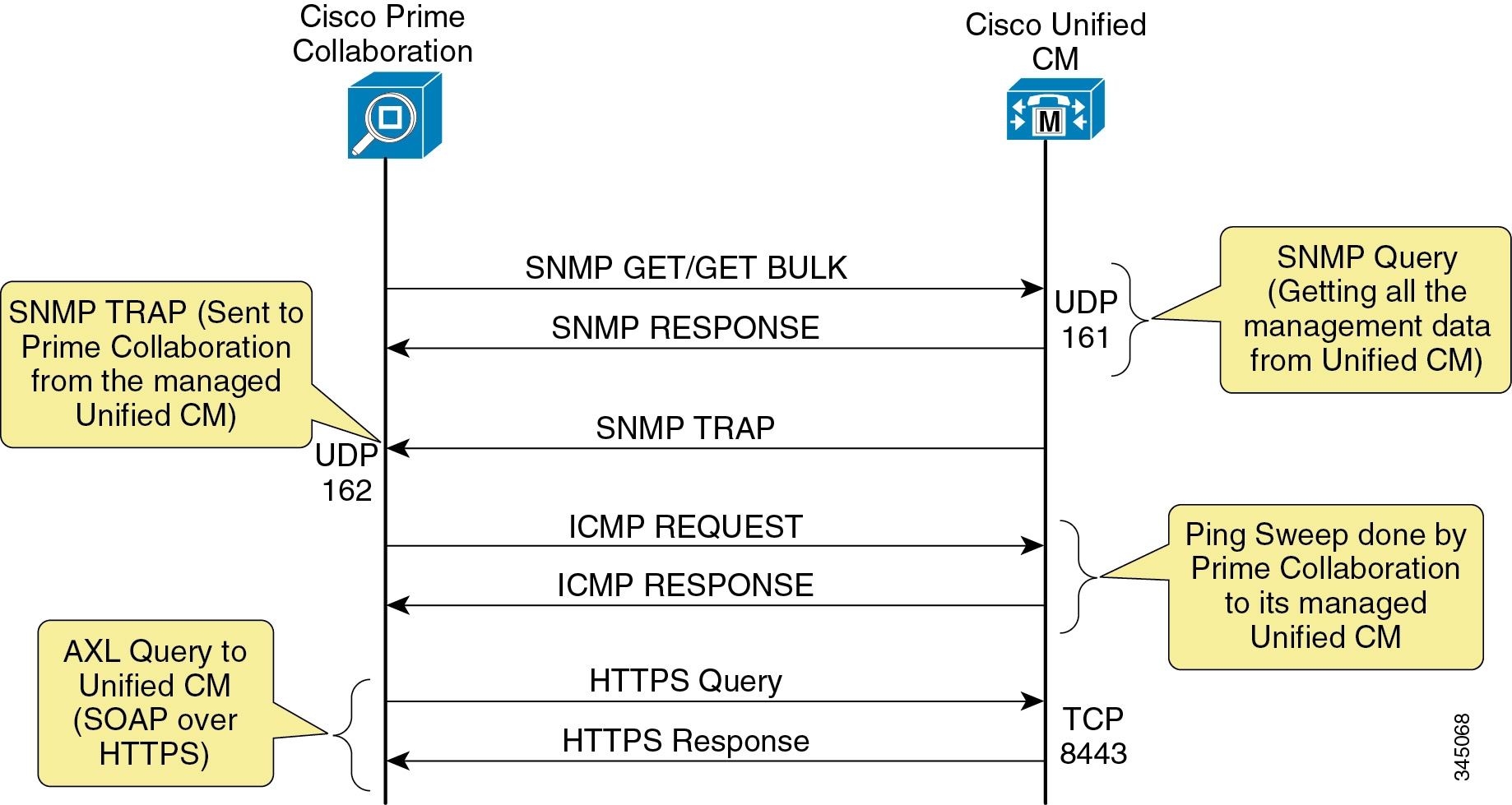
Cisco Prime Collaboration interfaces with other devices in the network in the following ways:
- Simple Network Management protocol (SNMP) to manage all Cisco Unified Communications servers, gateways, and switches.
- Administrative XML Layer (AXL) to manage Unified CM. AXL is implemented as a Simple Object Access Protocol (SOAP) over HTTPS web service.
- HTTP to the IP phone to collect serial number and switch information. HTTP must be enabled on the IP phones.
- Enhanced event processing with Cisco Unified CM remote syslog integration, and leveraging the Cisco Real-Time Monitoring Tool (RTMT) interface for pre-collected Unified CM cluster-wide data
- Skinny Client Control Protocol (SCCP) and Session Initiation Protocol (SIP) to Cisco Unified IP Phones for synthetic tests.
- Internet Control Message Protocol (ICMP) or Ping Sweep for Cisco IOS routers and switches, and for other voice as well as non-voice devices.
- Windows Management Instrumentation (WMI) for Cisco Unity servers.
Figure 29-1 shows the system-level overview of how Prime Collaboration leverages multiple interfaces with Unified CM to gather performance counters and alarms.
Figure 29-1 Prime Collaboration and Unified CM System-Level Integration
Call Quality Monitoring (Service Experience)
Cisco Prime Collaboration Assurance Advanced monitors the quality of calls on the Cisco Unified Communications network. It relies on Unified CM, Cisco 1040 Sensors, and Network Analysis Modules (NAMs) to monitor and gather quality statistics on real calls rather than simulated calls in the network. Then it compares the collected quality statistics against predefined thresholds.
Prime Collaboration Assurance Advanced is also responsible for sending voice quality information to Cisco Prime Analytics (available only with Prime Collaboration Advanced) so that Analytics can perform call data analysis and generate reports.
Note![]() A set of global call quality thresholds can be defined as one per supported codec type. Different thresholds can be grouped together based on the Cisco 1040 Sensor being implemented or the Unified CM cluster being monitored.
A set of global call quality thresholds can be defined as one per supported codec type. Different thresholds can be grouped together based on the Cisco 1040 Sensor being implemented or the Unified CM cluster being monitored.
Voice Quality Measurement
Voice quality is the qualitative and quantitative measure of the sound and conversational quality of the IP phone call. Voice quality measurement describes and evaluates the clarity and intelligibility of voice conversations. Prime Collaboration uses the Cisco 1040 Sensor, the Network Analysis Module (NAM), and Unified CM to monitor and report voice quality information.
Cisco 1040 Sensor Voice Quality Monitoring
The Cisco 1040 Sensor is a hardware device that predicts a subjective quality rating that an average listener might experience on the VoIP calls. It operates by measuring various quality impairment metrics that are included in the IP header of RTP streams, such as packet loss, delay, jitter, and concealment ratio. This computed quality rating is converted to a Mean Opinion Score (MOS) value. The MOS value is included in syslog messages that are sent to Prime Collaboration every 60 seconds, thus the Cisco 1040 Sensor monitors the voice quality almost on a real-time basis.
The Cisco 1040 Sensor has two Fast Ethernet interfaces, one of which is used to manage the sensor itself and the other is connected to the Switch Port Analyzer (SPAN) port on the Cisco Catalyst switch to monitor the actual RTP streams. To monitor voice quality of calls across the WAN, you must deploy a pair of Cisco 1040 Sensors at both sides of the WAN cloud, as illustrated in Figure 29-2.
Figure 29-2 Voice Quality Monitoring with the Cisco 1040 Sensor
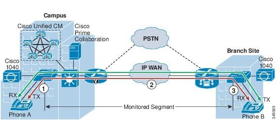
There are two call legs, transmitting and receiving, for each phone. Each call leg can be divided into three segments along the call path. For example, for the transmitting call leg of phone A in Figure 29-2, segment 1 runs between phone A and the campus access switch, segment 2 is between the two access switches, and segment 3 is between the access switch at the branch site and phone B. Segments 1 and 3 are within a local area network, which presents the fewest transmission impairments to voice quality. Therefore, it is reasonably safe to assume that voice quality degradation will not occur in these two segments, and it is unnecessary to monitor those RTP streams.
Segment 2 spans across the WAN circuit and several network devices along the call path. It is more likely to experience degradation of voice quality due to packet loss, delay, and jitter inherent in the WAN. Therefore, the RTP streams (from campus to branch) should be monitored by the Cisco 1040 Sensor at the branch site. By the same token, the sensor in the central site should monitor the incoming RTP streams in that segment across the WAN. These RTP streams provide important voice quality statistics, and their associated MOS values should be analyzed carefully.
Strategic vs. Tactical Monitoring
There are two strategies for deploying Cisco 1040 Sensors: strategic monitoring and tactical monitoring. With strategic monitoring, the Cisco 1040 Sensor is deployed to continuously monitor all or subsets of IP phones in the network. With tactical monitoring, the Cisco 1040 Sensor is deployed in a site where a voice quality issue has been identified. The Cisco 1040 Sensor complies with FCC Class-B standards, and it can be deployed easily in the enterprise environment.
In a small network, Cisco recommends deploying strategic monitoring to monitor all IP phones on a continuous basis. In a medium to large network, Cisco recommends deploying strategic monitoring to continuously monitor a subset of IP phones, while using tactical monitoring to troubleshoot any voice quality issues experienced by the rest of the IP phones.
Design Considerations for the Cisco 1040 Sensor
Consider the following design factors when deploying a Cisco 1040 Sensor:
- A Cisco 1040 Sensor can monitor 100 simultaneous RTP streams. By monitoring the incoming RTP stream only, as illustrated in Figure 29-2, the Cisco 1040 Sensor can provide the full benefit of monitoring 100 (instead of 50) simultaneous voice calls. An environment with a high call volume tends to require the use of more Cisco 1040 Sensors.
- If there are more RTP streams than the Cisco 1040 Sensor can handle, the Cisco 1040 Sensor will randomly select RTP streams.
- The Cisco 1040 Sensor utilizes the SPAN port on the Cisco Catalyst Switch to monitor the actual RTP streams. Different types of Catalyst switches have different quantities of SPAN ports that can be configured. For example, a maximum of two SPAN ports can be configured on the Cisco Catalyst 6500 and 4500 switches, while the maximum limit for Cisco Catalyst 3550 switch is only one. Therefore, the types of Catalyst switches that have been deployed in the network will determine how many Cisco 1040 Sensors can be deployed.
- If there is a trunking connection between multiple Cisco Catalyst switches and if the call volume is low, there is no need to deploy a Cisco 1040 Sensor for every Catalyst switch. Remote Switch Port Analyzer (RSPAN) can be used so that a single Cisco 1040 Sensor can monitor IP phones on other switches within the same VLAN.
- It is inefficient to deploy a Cisco 1040 Sensor at every site that has just a few IP phones and a small call volume. In such cases, Cisco Encapsulated Remote Switched Port Analyzer (ERSPAN) can be used so that one Cisco 1040 Sensor can monitor voice streams across multiple networks.
Unified CM Call Quality Monitoring
Unified CM stores end-of-call video and audio information and metrics in its call detail records (CDRs) and call management records (CMRs). The CMRs and CDRs are transferred to Prime Collaboration via Secure File Transfer Protocol (SFTP) every 60 seconds. To integrate with Unified CM, Prime Collaboration must be configured as a Billing Application Server in the Unified CM Unified Serviceability configuration web page. Up to three Billing Application Servers can be configured per Unified CM cluster. The following settings must be configured for the Billing Application Server:
- Hostname or IP address of the Prime Collaboration Assurance virtual machine
- Username and password for SFTP file transfer
- Protocol: SFTP
- Directory path on the Prime Collaboration virtual machine to which CDR and CMR files are transferred
Unified CM utilizes the Cisco Voice Transmission Quality (CVTQ) algorithm as one means to monitor voice quality. CVTQ is based on the Klirrfaktor (K-factor) method to estimate the MOS value of voice calls. At the end of each call, Unified CM stores the MOS value received from the endpoint in a CMR.
CVTQ has been supported natively since Unified CM 7. x, with Cisco Unified IP Phones running in both SCCP and SIP modes. The phone models that support CVTQ are listed in the compatibility information at
http://www.cisco.com/en/US/products/ps6535/products_device_support_tables_list.html
As a comparison to the Cisco 1040 Sensor, which performs a full-depth inspection on various quality impairment metrics, the K-factor method inspects only one dimension of quality impairments, packet loss, which is really a network effect. Thus, CVTQ is a less sophisticated algorithm than the one that the Cisco 1040 Sensor uses to monitor the quality of calls. Cisco recommends using CVTQ to flag a voice quality issue and using the Cisco 1040 Sensor to validate and troubleshoot the issue.
Cisco Network Analysis Module (NAM)
Cisco NAM is a traffic analysis module that leverages Remote Monitoring (RMON) and some SNMP Management Information Bases (MIBs) to enable network administrators to view all layers of the Unified Communications infrastructure to monitor, analyze, and troubleshoot applications and network services such as QoS for voice and video applications. Voice instrumentation added in Cisco NAM 4.0 enables NAM integration with Prime Collaboration for call metrics through NAM-embedded data collection and performance analysis.
The Cisco NAM complements Prime Collaboration to deliver an enterprise-wide voice management solution. The NAM Appliances come with a graphical user interface for troubleshooting and analysis, and they provide a rich feature set for voice quality analysis with RTP and voice control and signaling monitoring.
Cisco Prime Collaboration polls the NAM every 60 seconds for voice quality metrics. It then consolidates the data from both the Cisco 1040 Sensor and NAM, and it uses the same method for MOS calculation on both the Cisco 1040 Sensor and NAM. This enables Prime Collaboration to correlate CDR and call stream reports from the Cisco 1040 Sensor and NAM for enhanced analysis.
For more information on Cisco NAM, refer to the following site:
Comparison of Voice Quality Monitoring Methods
Cisco 1040 Sensors, CVTQ, and NAM complement each other and provide a total solution for voice quality measurement. The following list notes key differences between voice quality monitoring with the Cisco 1040 Sensor, CVTQ, and Cisco NAM:
- The Cisco 1040 Sensor monitors voice calls based on packet loss, delay, jitter, and concealment ratio. CVTQ monitors voice calls based on packet loss only.
- The Cisco 1040 Sensor and Cisco NAM provide voice quality statistics every 60 seconds. CVTQ provides voice quality statistics after the call is completed.
- The Cisco 1040 Sensor is compatible with all Cisco Unified CM releases and all types of endpoints connecting to the Cisco Catalyst switch. CVTQ supports only Unified CM 4.2 and later releases.
- For intercluster calls, the Cisco 1040 Sensor monitors the end-to-end call segment. CVTQ monitors only the call segment within its own cluster.
- Cisco recommends using the Cisco 1040 Sensor to monitor key IP phone devices, gateway devices, and application servers in the network and to investigate and troubleshoot voice quality issues. CVTQ-based voice quality monitoring should be used to gauge the overall voice call quality in the network.
Even if CVTQ is not used, Prime Collaboration uses Unified CM CDR information to correlate with the NAM report for the following metrics:
Trunk Utilization
Cisco Prime Collaboration provides real-time Unified CM trunk utilization performance graphs. It is also tightly integrated with Cisco Prime Analytics in order to provide the call information it collects to Analytics for long-term trending and reporting purposes. The call information is provided from the CDR and CMR records Prime Collaboration gathers from Unified CM.
Failover and Redundancy
The Unified CM publisher server is responsible for transferring CDR and CMR files to Prime Collaboration via SFTP. If the publisher server is unavailable, there is no failover mechanism for Prime Collaboration to obtain the new CDR and CMR files that contain MOS values of calls in the Unified CM cluster.
Voice Monitoring Capabilities
Cisco Prime Collaboration supports the following voice quality monitoring capacities:
–![]() 5,000 sensor-based RTP streams per minute (with Cisco 1040 Sensors or NAM modules)
5,000 sensor-based RTP streams per minute (with Cisco 1040 Sensors or NAM modules)
–![]() 1,600 CVTQ-based calls per minute
1,600 CVTQ-based calls per minute
–![]() 1,500 RTP streams and 666 CVTQ calls per minute
1,500 RTP streams and 666 CVTQ calls per minute
- Prime Collaboration automatically selects and gathers voice quality information (via CDR and CMR files) for all Cisco Unified IP Phones configured in a given Unified CM cluster. There is no configuration option to monitor only certain IP phones in the cluster.
Note![]() When Cisco Prime Collaboration is operating at full capacity, its projected database growth (for Syslog, CDR, and CMR files) is estimated to be about 2.4 GB per day.
When Cisco Prime Collaboration is operating at full capacity, its projected database growth (for Syslog, CDR, and CMR files) is estimated to be about 2.4 GB per day.
Assurance Ports and Protocol
Table 29-3 lists the ports used by the various protocol interfaces for Cisco Prime Collaboration for Assurance. Cisco recommends opening these ports in the corporate internal firewalls (if applicable) to allow communication between Prime Collaboration and other devices in the network
|
|
|
|
|---|---|---|
Syslog1 |
||
SCCP2 |
||
TFTP3 |
||
Note![]() The Cisco NAM is accessed remotely over HTTPS with a non-default port. Prime Collaboration will authenticate with each Cisco NAM and maintain the HTTP/S session.
The Cisco NAM is accessed remotely over HTTPS with a non-default port. Prime Collaboration will authenticate with each Cisco NAM and maintain the HTTP/S session.
All the management traffic (SNMP) originating from Prime Collaboration or managed devices is marked with a default marking of DSCP 0x00 (PHB 0). The goal of network management systems is to respond to any problem or misbehavior in the network. To ensure proper and reliable monitoring, network management data must be prioritized. Implementing QoS mechanisms ensures low packet delay, low loss, and low jitter. Cisco recommends marking the network management traffic with an IP Precedence of 2, or DSCP 0x16 (PHB CS2), and providing a minimal bandwidth guarantee. The DSCP value must be configured in the Windows Operating System.
If managed devices are behind a firewall, the firewall must be configured to allow management traffic. Prime Collaboration has limited support in a network that uses Network Address Translation (NAT). It must have IP and SNMP connectivity from the Prime Collaboration server to the NAT IP addresses for the devices behind the NAT. Prime Collaboration contains static NAT support.
Bandwidth Requirements
Prime Collaboration polls the managed devices for operational status information at every configured interval, and it has the potential to contain a lot of important management data. Bandwidth must be provisioned for management data, especially if you have many managed devices over a low-speed WAN. The amount of traffic varies for different types of managed devices. For example, more management messages may be seen when monitoring Unified CM as compared to monitoring a Cisco Voice Gateway. Also, the amount of management traffic will vary if the managed devices are in a monitored or partially monitored state and if any synthetic tests are performed. Prime Collaboration has a Bandwidth Estimator that is available at
Analytics
Cisco Prime Collaboration Analytics provides many additional benefits to Prime Assurance. It provides trending to identify degradation over time. It can also utilize trending to provide capacity planning and quality of service (QoS) information. The capacity planning feature allows administrators to plan for growth and also to identify over- or under-utilized resources (for example, TelePresence endpoints) in their network. Analytics can generate automated reports that provide actionable information to CIOs and IT planners. Reports can be customized to meet unique business needs.
Analytics supports the following predefined dashboards:
Custom dashboards and dashlets can also be created if desired.
The Technology Adoption dashboard provides visibility into the progress of your voice and video deployment by showing devices deployed and minutes used. This information allows for more intelligent technology investment decisions based on current adoption analysis.
The Asset Usage dashboard shows long-term utilization trends for collaboration network resources. It provides information such as least used and most used resources such as endpoints.
The Traffic Analysis dashboard provides a means to analyze long-term service quality issues and identify voice and video traffic patterns. It offers options to show the top N callers, top N dialed numbers, top N off-net traffic locations, and top N call traffic locations.
The Capacity Analysis dashboard provides options that allow tracking of unused or under-utilized voice and video assets such as conferencing devices, call admission control bandwidth, and trunks. The information provided can assist in optimizing equipment and network costs.
The Service Experience dashboard helps identify call quality issues in the collaboration deployment. It can show top N endpoints with quality issues or allow filtering based on quality level. It also provides a means to analyze call failures, identify service usage by group of users or endpoints, and help effectively allocate the IT expense.
For detailed information on feature support and functionality, refer to the Cisco Prime Collaboration Analytics product documentation available at http://www.cisco.com.
Note![]() Currently there is no redundancy or failover support with Analytics.
Currently there is no redundancy or failover support with Analytics.
Analytics Server Performance
Analytics is included in the Prime Assurance OVA and runs on the same virtual machine. Note that Analytics does require a separate license.
Provisioning
Prime Collaboration Provisioning is available in the following forms:
- Prime Collaboration Provisioning Standard — Available with Cisco Collaboration Systems 10. x releases (Cisco Unified CM 10. x and Cisco Unity Connection 10. x).
- Prime Collaboration Provisioning Advanced — Available for Cisco Unified Communications System 8.0 and later releases.
Prime Collaboration Provisioning Standard is a simplified version of Cisco Prime Collaboration Provisioning. It provides simplified provisioning across all collaboration services. You can provision all services including phones, voicemail clients, and video endpoints. Provisioning support is available for a single Unified Communications cluster with limited authorization roles.
Advanced Provisioning provides more advanced features such as delegation to individual domains, template support for configuring infrastructure instances, advanced batch provisioning, and so on. Table 29-4 lists the features available in Prime Collaboration Provisioning Standard and Advanced.
Cisco Prime Collaboration provides a simplified web-based provisioning interface for both new and existing deployments of Cisco Unified Communications Manager (Unified CM), Cisco Unified Communications Manager Express (Unified CME), Cisco Unity, Cisco Unity Connection, and Cisco Unity Express. Prime Collaboration provides provisioning for both the infrastructure and subscribers for Day 1 and Day 2 needs. Day 1 needs include configuring new deployments and adding more sites or locations; Day 2 needs include services for ongoing moves, adds, and changes on various components of the Cisco Unified Communications solution.
Cisco Prime Collaboration also exposes northbound APIs to allow Cisco and third parties to integrate with external applications such as HR systems, custom or branded user portals, other provisioning systems, and directory servers.
For details on Prime Collaboration system requirements and installation steps, provisioning users and the infrastructure of supported components, and capacity information, refer to the Cisco Prime Collaboration documentation available at
http://www.cisco.com/en/US/products/ps11480/index.html
To provide a better understanding of how Prime Collaboration can be used as a network management solution for provisioning various Cisco Unified Communications components, the next section presents some of the basic concepts of Prime Collaboration.
Provisioning Concepts
Cisco Prime Collaboration serves as a provisioning interface for the following components of a Cisco Unified Communications system:
–![]() Cisco Unified Communication Manager (Unified CM)
Cisco Unified Communication Manager (Unified CM)
–![]() Cisco Unified Communications Manager Express (Unified CME)
Cisco Unified Communications Manager Express (Unified CME)
–![]() Cisco VG224, VG204, and VG202 Analog Voice Gateways
Cisco VG224, VG204, and VG202 Analog Voice Gateways
Note![]() For more information on component version compatibility, refer to the Prime Collaboration information at http://www.cisco.com/en/US/products/ps11480/index.html.
For more information on component version compatibility, refer to the Prime Collaboration information at http://www.cisco.com/en/US/products/ps11480/index.html.
The following sections describe some of the Prime Collaboration concepts involved in configuring those components.
Domains are used for administrative purposes to create multiple logical groups within a system. Domains have the following characteristics:
- A domain can be mapped to a geographical location or an organization unit.
- One domain can contain multiple call processors and multiple optional message processors.
- A given call processor or message processor can be a member of multiple domains.
- A domain can partition subscribers so that they can be administered separately.
Service areas represent offices. Service areas determine the dial plans and other voice-related configuration settings in the domain. In reality, each office may have multiple service areas. The service area determines attributes such as device group, route partition, and calling search space used within Unified CM. Service areas have the following characteristics:
- Each service area is assigned to a single call processor and one optional message processor.
- Each service area should be associated with one dial plan.
When deploying a new site or making moves, adds and changes to an existing site, users make all changes to the underlying systems through a two-stage process of creating an order and then processing that order. You can set policies for both of these stages. For example, you can configure the system so that one group of users can only create and submit orders, while another group of users can view and perform processing-related activities. Prime Collaboration contains an automation engine that performs the order processing, including service activation and business flow, based on how Prime Collaboration is configured.
The workflow coordinates activities of the ordering process (approval, phone assignment, shipping, and receiving).
Prime Collaboration enables you to configure Unified CM, Unified CME, Cisco Unity, Cisco Unity Express, and Cisco Unity Connection in a consistent way through the use of configuration templates. You can use these templates to configure any of these products, to perform an incremental rollout on these existing products, and to deploy a new service across existing customers.
Creating users and provisioning their services can also be done automatically through batch provisioning for rolling out a new office or transitioning from legacy systems.
Best Practices
The following best practices and guidelines apply when using Prime Collaboration to provision Cisco Unified Communications components for any new and/or existing deployments:
- Managed devices must be up and running before using Prime Collaboration for further day-one activities such as rolling out a new site and day-two activities such as moves, adds, and changes.
- Pre-configuration is required for Cisco Unified CM, Cisco Unity, Unified CME, Survivable Remote Site Telephony (SRST), Cisco Unity Express, and Cisco IM and Presence Service.
- Define the correct domains, service areas, and provisioning attributes.
- Modify only the workflow rules if necessary.
- Consider the use of Subscriber Types, Advanced Rule settings, and other configuration parameters.
The following basic tasks help support these best practices:
- Add call processors such as Unified CM, and/or Unified CME and message processors such as Cisco Unity, Unity Connection, and/or Unity Express.
- Create domains and assign call processors and message processors to the created domains.
- Provision the voice network by creating and using templates to configure Unified CMs or Unified CMEs, or import current voice infrastructure configurations from an existing deployment.
- Perform bulk synchronization of LDAP users into Prime Collaboration, if applicable.
- Set up the deployment by creating service areas for each domain (typically one per dial plan) and assigning subscriber (user) types to each service area.
- Create administrative users for each domain.
- Order, update, or change subscriber or user services.
Prime Collaboration Design Considerations
The following design considerations apply to Prime Collaboration for provisioning:
–![]() Create a single domain for multiple sites, with multiple call processors and multiple message processors.
Create a single domain for multiple sites, with multiple call processors and multiple message processors.
–![]() Create a domain for each site, consisting of one call processor and zero or more optional message processors.
Create a domain for each site, consisting of one call processor and zero or more optional message processors.
–![]() Create multiple domains if different administrators are required to manage a subset of the subscribers.
Create multiple domains if different administrators are required to manage a subset of the subscribers.
- Create multiple service areas for multiple dial plans.
- Add only the Unified CM publisher as the call processor for Prime Collaboration. Any changes made to the Unified CM publisher through Prime Collaboration will be synchronized to all the Unified CM subscriber servers.
- Use configuration templates for Unified CM, Unified CME, or Cisco Unity Express.
- Use Cisco IOS commands for Unified CME and Cisco Unity Express configuration templates.
- Add Cisco Unified CM infrastructure data objects for Unified CM configuration templates.
- Change and modify the existing configuration templates for batch provisioning for large quantities of phones and lines (DNs).
- Create multiple domains if you want different domain administrators to manage different sets of subscribers for Day 2 moves, adds, and changes of services (such as phones, lines, and voicemail), even for a single-site deployment.
- Create one service area for one dial plan.
- Create multiple service areas if multiple dial plans are required for the device pools, location, calling search space, and phones.
- Prime Collaboration is an IPv6-aware application with the following characteristics:
–![]() Prime Collaboration communicates with Unified CM over an IPv4 link. The Prime Collaboration user configuration interface allows users to enter only IPv4 IP addresses because Unified CM has SOAP AXL interfaces in IPv4 only. Therefore, Prime Collaboration must use IPv4 addresses to communicate with the AXL interfaces on Unified CM.
Prime Collaboration communicates with Unified CM over an IPv4 link. The Prime Collaboration user configuration interface allows users to enter only IPv4 IP addresses because Unified CM has SOAP AXL interfaces in IPv4 only. Therefore, Prime Collaboration must use IPv4 addresses to communicate with the AXL interfaces on Unified CM.
–![]() Prime Collaboration handles the IPv6 addresses contained in SIP trunk AXL response messages.
Prime Collaboration handles the IPv6 addresses contained in SIP trunk AXL response messages.
–![]() Support of IPv6-aware functions does not affect support for current Cisco Unified Communications Manager Express, Cisco Unity, Cisco Unity Express, and Cisco Unity Connection devices.
Support of IPv6-aware functions does not affect support for current Cisco Unified Communications Manager Express, Cisco Unity, Cisco Unity Express, and Cisco Unity Connection devices.
Redundancy and Failover
If Prime Collaboration fails in the middle of the configuration process, changes made to the configured devices from the Prime Collaboration GUI might not be saved and cannot be restored. Administrators must use manual steps to continue the configuration process by using other tools such as telnet or login (HTTP) to the managed devices until Prime Collaboration comes back live. Manually added configuration changes to the managed device will not automatically show up in the Prime Collaboration dashboard or database unless you also perform synchronization from Prime Collaboration for the call processors (Unified CM and/or Unified CME), message processors (Cisco Unity, Unity Connection, and/or Unity Express), and domains.
Provisioning Ports and Protocol
Table 29-5 lists the ports used by the various protocol interfaces for Prime Collaboration. Cisco recommends opening those ports in the corporate internal firewalls (if applicable) to allow communication between Prime Collaboration and other devices in the network.
|
|
|
|
|---|---|---|
HTTPS 2 |
||
SSH6 |
||
Telnet 3 |
||
Database7 |
Prime Collaboration and Medianet
When a network includes medianet-capable devices and endpoints, Prime Collaboration provides even deeper network path visibility, down to the granularity of media flow statistics. For Cisco devices with medianet, jitter, packet-loss, and differentiated services code point (DSCP) information is displayed to locate bottlenecks and impairments in the network and to mitigate them before they cause technical problems.
Prime Collaboration provides troubleshooting tools for ongoing video sessions using medianet. You can trace the path of the video call and see the topology of all the devices in between the two video endpoints. If medianet-enabled devices are present, it can also display more detailed impairment information on each device, thus helping to troubleshoot the exact point where the session is having an issue.
To tackle these new challenges when deploying video and collaboration applications, system designers need to take an architectural approach. Medianet is Cisco's recommended best-practice architecture for video and collaboration deployment. The medianet architecture extends the network boundary to include the endpoints. The network works together with the endpoints in order to scale, optimize, and enhance the performance of collaboration components.
The idea behind this approach comes from the realization that the endpoints or applications are the place in the architecture where the most information about the applications resides. The endpoints can communicate with the network, making the network media-aware and providing it with important information that can be used to make intelligent decisions. The endpoints and collaboration applications use Media Services Interface (MSI) to communicate with the network and send valuable information about the media flows to the network. With the help of MSI, the endpoints become network aware and can request intelligent network services, for example, to initiate troubleshooting.
Figure 29-3 illustrates a typical use case for Performance Monitor with Prime Collaboration.
For more information about this use case, refer to the Cisco Medianet Deployment Guide, available at
http://www.cisco.com/c/en/us/solutions/enterprise/enterprise-medianet/solution-overview-listing.html
Figure 29-3 Performance Monitor Used with Prime Collaboration
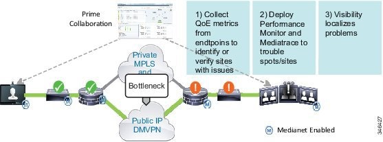
Figure 29-3 shows the following steps:
1.![]() Prime Collaboration collects the quality of experience (QoE) metrics from the endpoints and displays them in Session Diagnostics, as shown in Figure 29-4.
Prime Collaboration collects the quality of experience (QoE) metrics from the endpoints and displays them in Session Diagnostics, as shown in Figure 29-4.
2.![]() Prime Collaboration alerts the administrator if there is degradation in the quality of the session.
Prime Collaboration alerts the administrator if there is degradation in the quality of the session.
Figure 29-4 Viewing Session Diagnostic Information in Prime Collaboration
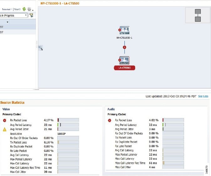
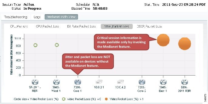
3.![]() Figure 29-5 shows how the administrator can generate a mediatrace into the network to gather information from the network elements. Figure 29-6 shows the Medianet Path View of the mediatrace. The graphical representation of the network metrics makes it easy to determine where the problem is.
Figure 29-5 shows how the administrator can generate a mediatrace into the network to gather information from the network elements. Figure 29-6 shows the Medianet Path View of the mediatrace. The graphical representation of the network metrics makes it easy to determine where the problem is.
Figure 29-5 Starting a Mediatrace with Prime Collaboration
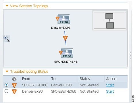
Figure 29-6 Results of a Mediatrace Showing Path View in Prime Collaboration
For more details, refer to the Performing Diagnostics section in the latest version of the Cisco Prime Collaboration Assurance Guide - Advanced, available at
http://www.cisco.com/en/US/products/ps12363/products_user_guide_list.html
Cisco TelePresence Management Suite (TMS)
Cisco TelePresence Management Suite (TMS) supports scheduling of video endpoint and conferencing devices. Scheduling ensures endpoint and port resource availability and provides convenient methods to connect to TelePresence conferences. Most organizations already use calendaring applications to schedule conferences. In this case, calendaring integration enables users to schedule conferences with their existing calendaring client.
Calendaring Options
Calendaring integration gives users the ability to schedule video conferences and invite participants directly from their calendaring application while viewing availability information of resources regardless of where meetings are created. Calendaring options include:
Allows conference organizers to schedule conferences using their Microsoft Outlook client. For more information on Cisco TMSXE, refer to the product documentation available at
http://www.cisco.com/en/US/products/ps11472/tsd_products_support_series_home.html
Allows conference organizers to schedule conferences using their IBM Lotus Notes client. For more information on Cisco TMSXN, refer to the product documentation available at
http://www.cisco.com/en/US/products/ps11472/tsd_products_support_series_home.html
Allows conference organizers to schedule conferences using additional groupware calendaring systems through API integration. For more information on Cisco TMSBA, refer to the TMSBA Programing Reference Guide located at
http://www.cisco.com/en/US/products/ps11472/tsd_products_support_series_home.html
Allows users or administrators to schedule conferences through a web-based interface. This is part of the Cisco TMS core application and does not require additional installation or integration.
Cisco highly recommends integrating your corporate calendaring application with the scheduling and management platform chosen by your organization. However, you may also choose to schedule conferences using the TMS web interfaces.
When deploying Cisco TMS calendar integration as your corporate calendaring application, choose the appropriate extension for your environment. For example, if Microsoft Exchange is the existing calendaring application, use TMSXE. TMSXE is installed on a standalone server, and TMSXN is installed on the Lotus Domino server. The integration software is installed separately from Cisco TMS and communicates with your calendaring server using HTTP or HTTPS.
Cisco recommends having your video conferencing resources (Cisco TelePresence Video Communication Server or Cisco MCU) dedicated for either scheduled or permanent/instant conferences. This is because permanent or instant conferences could consume scheduled resources, which would result in undesirable consequences on the scheduled conferences, such as scheduled video participants being unable to join or joining as audio-only due to lack of resources on the server.
Reporting
Cisco TMS provides various types of reporting and analysis functionality, including:
- Asset management reports: ticket logs, device events, device alarms, and connectivity
- Detailed call history reports for managed endpoints and infrastructure
- Scheduling activity reports, including user-based, scheduling interface used, conference event logs, and conference reports
However, some of these functions work only in certain deployments. For example, when an endpoint such as the Cisco TelePresence TX9000 or Cisco TelePresence System EX90 is registered to Cisco Unified Communications Manager (Unified CM), Cisco TMS cannot generate reports for that endpoint. Cisco TMS can generate only call history and call detail record (CDR) reports for an endpoint registered to the Cisco TelePresence Video Communication Server (VCS). For those endpoints that are registered to Unified CM, CDRs can be downloaded from Unified CM.
Organizations that require more customized reports, business knowledge, and integration with Business Intelligence Applications can use the Cisco TelePresence Management Suite Analytics Extension (TMSAE), which is an online analytical processing system for Cisco TMS that provides advanced reporting functionality for your video network. For more information on Cisco TMSAE, refer to the product documentation available at
http://www.cisco.com/en/US/products/ps11472/tsd_products_support_series_home.html
Management
The main functions of management in the TelePresence environment include: provisioning, monitoring, maintenance, and resource management. Cisco TelePresence Management Suite (Cisco TMS) enables management of the TelePresence environment, along with a scheduling interface that it supports in a TelePresence environment.
Endpoint and Infrastructure Management
Cisco TMS can manage endpoints registered to both Cisco VCS and Cisco Unified CM. There are two types of device management: direct managed and provisioned.
Direct-managed devices are manually added into the Cisco TMS system navigator. Cisco TMS supports 5,000 direct-managed devices. Cisco TMS communicates with the endpoints directly via HTTP or SNMP protocols. When a direct-managed endpoint is registered to Unified CM, Unified CM handles most management capabilities such as software upgrades. When a direct-managed endpoint is registered to Cisco VCS, Cisco TMS handles management and provisioning of the endpoint, including capabilities such as software upgrades.
Cisco TMS can also directly manage infrastructure devices such as Cisco VCS, Cisco TelePresence Server, Cisco MCU's, and others. Currently Cisco TMS supports scheduling and management of conferencing devices registered with Cisco VCS only.
Provisioned endpoints are not in the TMS system navigator, but rather are provisioned by Cisco TMS through the Cisco TMS Provisioning Extension (TMSPE). Cisco TMS supports 100,000 provisioned devices. The provisioning method dramatically increases the scale that Cisco TMS can support. It also simplifies the procedure for a bulk deployment because there is no need to add the systems manually. However, Cisco TMS has less control on provisioned endpoints compared to direct-managed endpoints. In addition, scheduling is not supported for provisioned endpoints.
Cisco TMS provides the functionality of phone books for direct-managed endpoints registered to Cisco VCS as well as provisioned endpoints. Phone books provide ease of locating users and dialing out.
Cisco TMS also provides interfaces to monitor both scheduled and instant video conferences.
For more information, refer the latest version of the Cisco TelePresence Management Suite Administrator Guide, available at
http://www.cisco.com/en/US/products/ps11338/prod_maintenance_guides_list.html
Provisioning
The Cisco TMS Provisioning Extension (TMSPE) is a provisioning application for Cisco TMS and Cisco VCS. Cisco TMSPE enables video conferencing network administrators to create and manage large deployable video conferencing solutions. Cisco TMSPE is an add-on replacement for the TMS agent on the Cisco TMS server, and it provides the following main features:
- Ability to import users from Microsoft and generic LDAP sources (LDAP, LDAPS, AD)
- User personalization and administrative device configuration control for devices supported by Cisco TMS Provisioning Extension (for example, Jabber video, Cisco IP Video Phone E20, and Cisco TelePresence System EX Series and MX Series)
- Multi-tiered phone books for devices supported by Cisco TMSPE
- End-user FindMe portal on Cisco TMS using Microsoft Active Directory (AD) login instead of Cisco VCS Web user interface
- Support for up to 100,0000 users and devices
For further information, refer to the latest version of the Cisco TelePresence Management Suite Provisioning Extension Deployment Guide, available at
http://www.cisco.com/en/US/products/ps11338/products_installation_and_configuration_guides_list.html
Phone books
Phone books help users maintain their contacts and dial them. Cisco TMS phone books can be created and populated from different sources such as Microsoft Active Directory (AD), Cisco Unified CM, an H.350 server, and gatekeepers.
There are two types of phone books: local phone books and global phone books. Local phone books (also called favorites) are a file stored on an endpoint specific to the end user. Contacts can be added, modified, and deleted as desired by the user.
Global or corporate phone books are pushed from Cisco TMS to the endpoints. They cannot be modified from the endpoint because they are automatically populated from AD, an H.350 server, or the local Cisco TMS database. Administrators can select the phone books for specific users and push them to the appropriate endpoints.
Maintenance and Monitoring
Cisco TMS has a Software Manager repository where the software images of endpoints and infrastructure devices can be added and then used to upgrade matching endpoints and infrastructure devices registered with Cisco VCS. Administrators can select a number of devices and upgrade them from Cisco TMS at one time. Cisco TMS provides the status of the upgrade. Using Cisco TMS to do upgrades is more convenient and easier than upgrading the endpoints and infrastructure devices manually.
Cisco TMS also provides monitoring capabilities for conferences. Cisco TMS lists all scheduled conferences, and the state of the conference (for example, Active) is displayed in TMS's Conference Control Center, with details of packet loss per participant for active conferences. Errors are displayed in TMS's Ticketing Service; for example, if there are configuration errors, Cisco TMS discovers them and opens a ticket associated with the appropriate device. Each ticket has an ID and severity level.
Additional Tools
In addition to the network management tools mentioned above, the following tools also provide troubleshooting and reporting capabilities for Cisco Unified Communications systems:
Cisco Unified Analysis Manager
Cisco Unified Analysis Manager is included with the Cisco Unified Communications Manager Real-Time Monitoring Tool (RTMT). RTMT runs as a client-side application and it uses HTTPS and TCP to monitor system performance, device status, device discovery, and CTI applications for Unified CM. RTMT can connect directly to devices via HTTPS to troubleshoot system problems.
Unlike the other RTMT functions, Unified Analysis Manager is unique in that it supports multiple Unified Communications elements instead of just one. When the Unified Analysis Manager is launched, it collects troubleshooting information from your Unified Communications system and provides an analysis of that information. You can use this information to perform your own troubleshooting operations, or you can send the information to Cisco Technical Assistance Center (TAC) for analysis.
Unified Analysis Manager supports the 8. x and later versions of the following Unified Communications elements:
- Cisco Unified Communications Manager
- Cisco Unified Contact Center Enterprise
- Cisco Unified Contact Center Express
- Cisco IOS Voice Gateways (3700 Series, 2800 Series, 3800 Series, 5350XM, and 5400XM)
- Cisco Unity Connection
- Cisco IM and Presence
Unified Analysis Manager provides the following key features and capabilities:
- Supports collection of Unified Communications application hardware, software, and license information from Unified Communications elements.
- Supports setting and resetting of trace level across Unified Communications elements.
- Supports collection and export to a define FTP server of log and trace files from Unified Communications elements.
- Supports analysis of the call path (call trace capability) across Unified Communications elements.
For more details on the report options, refer to the information about the Cisco Unified Analysis Manager in the Cisco Unified Real-Time Monitoring Tool Administration Guide, available at
http://www.cisco.com/en/US/docs/voice_ip_comm/cucm/service/8_5_1/rtmt/RTMT.html
Cisco Unified Reporting
The Cisco Unified Reporting web application generates reports for troubleshooting or inspecting Cisco Unified Communications Manager cluster data. It is a convenient tool that you can access from the Unified Communications Manager console. The tool facilitates gathering data from existing sources, comparing the data, and reporting irregularities. For example, you can view a report that shows the hosts file for all servers in the cluster. The application gathers information from the publisher server and each subscriber server. Each report provides data for all active cluster nodes that are accessible at the time the report is generated.
For example, the following reports can be used for general management of a Unified CM cluster:
- Unified CM Cluster Overview — Provides an overview of the cluster, including Unified CM version, hostname, and IP address of all servers, a summary of the hardware details, and so forth.
- Unified CM Device Counts Summary — Provides the number of devices by model and protocol that exist in the Cisco Unified Communications Manager database.
The following report can be used for debugging a Unified CM cluster:
The following report can be used for maintenance of a Unified CM cluster:
- Unified CM Database Status - Provides a snapshot of the health of the Unified CM database. This report should be generated before an upgrade to ensure the database is healthy.
For more information on the report options, refer to the latest version of the Cisco Unified Reporting Administration Guide, available at
http://www.cisco.com/en/US/products/sw/voicesw/ps556/prod_maintenance_guides_list.html
Integration with Cisco Unified Communications Deployment Models
This section discusses how to deploy Cisco Unified Network Management applications in various Cisco Unified Communications deployment models. For detailed information on the deployment models, see the chapter on Collaboration Deployment Models.
Campus
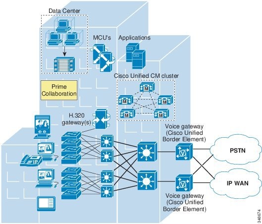
In the campus model, Cisco Unified Network Management applications, along with call processing agents, are deployed at a single site (or campus) with no telephony services provided over an IP WAN. An enterprise would typically deploy the single-site model over a LAN or metropolitan area network (MAN). Figure 29-7 illustrates the deployment of Cisco Unified Network Management applications in the single-site model.
The following design characteristics and recommendations apply to the single-site model for deploying Prime Collaboration:
- Cisco recommends deploying CVTQ-based voice quality monitoring to monitor overall voice quality in the network.
- Cisco recommends deploying the Cisco 1040 Sensor or NAM to monitor key IP phone devices, gateway devices, and application servers in the network and to investigate and troubleshoot voice quality issues.
Multisite WAN with Centralized Call Processing
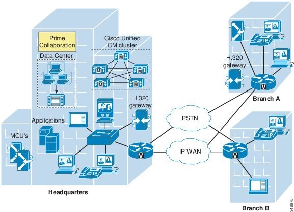
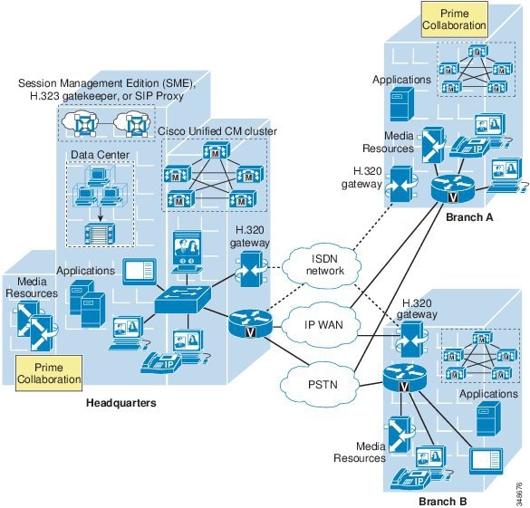
The multisite WAN model with centralized call processing is really an extension of single-site model, with an IP WAN between the central site and remote sites. The IP WAN is used to transport voice traffic between the sites and call control signaling between the central site and the remote sites. Figure 29-8 illustrates the deployment of Cisco Unified Network Management applications in a multisite WAN model with centralized call processing.
Figure 29-8 Multisite WAN Deployment with Centralized Call Processing
The following design characteristics and recommendations apply to the multisite model for deploying Prime Collaboration with centralized call processing:
- Cisco recommends deploying all network management applications (including Prime Collaboration) in the central site to locate them with the call processing agent. The benefit of such an implementation is that it keeps the network management traffic between call processing agent and network management applications within the LAN instead of sending that traffic over the WAN circuit.
- Multiple Prime Collaborations can be deployed, with each instance managing multi-site and multi-cluster Unified Communications environments. In this deployment scenario, Cisco recommends that you deploy a Manager of Managers (MoM). Each Prime Collaboration can provide real-time notifications to the higher-level MoM using SNMP traps, syslog notifications, and email to report the status of the network being monitored.
- Cisco recommends deploying CVTQ-based voice quality monitoring to monitor overall voice quality in the network.
- Cisco recommends using the Service Level Agreement (SLA) feature and Synthetic test feature to check for network infrastructure status.
- Cisco recommends deploying the Cisco 1040 Sensor or NAM to monitor key IP phone devices, gateway devices, and application servers in the network and to investigate and troubleshoot voice quality issues. In particular, Cisco recommends placing 1040 Sensors at branch sites in order to measure voice quality across the IP WAN.
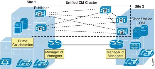
Multisite WAN with Distributed Call Processing
The multisite WAN model with distributed call processing consists of multiple independent sites, each with its own call processing agent connected to an IP WAN. Figure 29-9 illustrates the deployment of Cisco Unified Network Management applications in a multisite WAN model with distributed call processing.
Figure 29-9 Multisite WAN Deployment with Distributed Call Processing
A multisite WAN deployment with distributed call processing has many of the same requirements as a single site or a multisite WAN deployment with centralized call processing in terms of deploying Prime Collaboration. Follow the best practices and recommendations from these other models in addition to the ones listed here for the distributed call processing model:
- If only one Cisco Unified Network Management system is deployed to manage multiple Unified CM clusters, Cisco recommends deploying Prime Collaboration along with the Unified CM cluster that has the highest call volume and the most endpoints.
- Multiple Prime Collaborations can be deployed, with each instance managing multi-site and multi-cluster Unified Communications environments. In this deployment scenario, Cisco recommends that you deploy a Manager of Managers (MoM). Each Prime Collaboration can provide real-time notifications to the higher-level MoM using SNMP traps, syslog notifications, and email to report the status of the network being monitored.
- Cisco recommends deploying CVTQ-based voice quality monitoring to monitor overall voice quality in the network.
- Cisco recommends deploying the Cisco 1040 Sensor or NAM to monitor key IP phone devices, gateway devices, and application servers in the network and to investigate and troubleshoot voice quality issues. In particular, Cisco recommends placing 1040 Sensors at branch sites in order to measure voice quality across the IP WAN.
Clustering over the WAN
Clustering over the WAN refers to a single Cisco Unified CM cluster deployed across multiple sites that are connected by an IP WAN with QoS features enabled. This deployment model is designed to provide call processing resiliency if the IP WAN link fails. Figure 29-10 illustrates the deployment of Cisco Unified Network Management applications with clustering over the WAN.
Figure 29-10 Clustering over the WAN
Note![]() There is no native high-availability or redundancy support for Prime Collaboration with this model.
There is no native high-availability or redundancy support for Prime Collaboration with this model.
The following design characteristics and recommendations apply when deploying Prime Collaboration with clustering over the WAN:
- Cisco recommends deploying Prime Collaboration in the headquarter site where Unified CM publisher is located.
- Multiple Prime Collaborations can be deployed, with each instance managing multi-site and multi-cluster Unified Communications environments. In this deployment scenario, Cisco recommends that you deploy a Manager of Managers (MoM). Each Prime Collaboration can provide real-time notifications to the higher-level MoM using SNMP traps, syslog notifications, and email to report the status of the network being monitored.
- Cisco recommends deploying CVTQ-based voice quality monitoring to monitor overall voice quality in the network.
- Cisco recommends deploying the Cisco 1040 Sensor or NAM to monitor key IP phone devices, gateway devices, and application servers in the network and to investigate and troubleshoot voice quality issues.
 Feedback