- Welcome to DMS-Admin
- DMS-Admin Dashboard
- Licenses
- Server Operations
- Analyze Cisco DMS System Logs
- Allow or Disallow Video Transcoding
- Cisco Hinter for RTSP
- Authentication and Federated Identity
- Users and Groups
- Events and Notifications
- Configure Failover
- Welcome to Centralized DMP Management
- DMP Dashboard
- Register DMPs
- Organize DMPs in Groups
- Configure DMP Wi-Fi Settings
- Touchscreens, Projectors, and Displays
- DMP Remote Control and Its Emulation
- DMP User Permissions
- Media Assets and Embedded Software
- Schedule Media to Play and Commands to Run
- Content Distribution and Delivery
- Touchscreens, Projectors, and Displays
- Playlists
- Proof of Play
- Plan for and Manage Emergencies
- Welcome to Cisco Cast
- Redistribute Live TV
- Video on Demand
- Electronic Program Guide
- Look and Feel
- Video and Audio Signal Interfaces
- Supported Touchscreen Drivers
- Software UI and Field Reference Tables
- Elements to Choose A/V Settings from Menus
- Elements to Configure DMP Audio/Video Settings
- Elements to Control HDMI Display Autodetection
- Elements to Control Screen Resolution Autodetection
- Elements to Activate RS-232 for Supported LCD Display Brands ( except DMTech )
- Elements to Activate RS-232 for LCD Displays by DMTech
- FAQs and Troubleshooting

 You manage and operate presentation systems that are connected to remote DMP endpoints.
Concepts
Overview
A DMP transmits signals to a public presentation system that you choose, such as a flat-panel display or projector that is connected to the DMP.
• This system might use projection or display technologies that are analog or digital.
• It might support Standard Definition (SD), High Definition (HD), or both.
• Its output fidelity depends in part upon which signal cables (and adapters) connect it to your DMP.
–![]() With most modern, digital presentation systems, you can use an HDMI cable for both video and audio. Other such systems — including the 40-inch and 52-inch models in our LCD Professional Series — might not connect until you combine the HDMI cable with an HDMI-to-DVI adapter for video. However, DVI does not support the transmission of audio signals. In this case, you can use the provided audio cable for audio.
With most modern, digital presentation systems, you can use an HDMI cable for both video and audio. Other such systems — including the 40-inch and 52-inch models in our LCD Professional Series — might not connect until you combine the HDMI cable with an HDMI-to-DVI adapter for video. However, DVI does not support the transmission of audio signals. In this case, you can use the provided audio cable for audio.
–![]() When you use a Cisco-branded LCD display, a feature of Cisco Digital Signs software can detect automatically when your display is turned On or Off.
To connect one of these models to your DMP, you must use an RS-232 serial cable in addition to the video signal cable.
When you use a Cisco-branded LCD display, a feature of Cisco Digital Signs software can detect automatically when your display is turned On or Off.
To connect one of these models to your DMP, you must use an RS-232 serial cable in addition to the video signal cable.
Our centralized management features help you to manage a global IP network of digital signs for any purpose — in conference rooms, public venues, or executive offices.
Presentation System Concepts
Understand Which Displays Work Best with DMPs
We certify that DMPs work as designed with Cisco LCD flat-screen displays. All displays in this series are engineered for intensive use in public settings. See their technical documentation (CSCti35199) at http://cisco.com/en/US/products/ps10099/tsd_products_support_series_home.html .
In most cases, DMPs can use displays that comply with modern, international standards. We recommend the following if you must use a third-party display.
• High-definition, not standard-definition.
• Professional-grade, not consumer-grade. Digital signs and public IPTV installations run many more hours each day than a consumer-grade display is engineered to run. A consumer-grade system is likely to fail years sooner than a professional-grade system would under these circumstances.
• LCD, not plasma. Digital signage uses static images more often than it uses full-motion video. Most often, content is web-based or animated in Flash. The nature of these media types means that some pixels are not updated frequently in digital signage. LCDs are less susceptible to burn-in than plasma displays are. Even though image persistence is sometimes a problem on LCD displays, it is almost always self-correcting and is unlikely to occur when you follow manufacturer guidelines for managing your displays correctly.
Understand How to Choose Media Signal Cables

Caution Poorly shielded cable can sometimes promote undesired signal leakage (egress), interference from over-the-air signals (ingress), or crosstalk between cables that are in close physical proximity.
Special considerations apply when you obtain a signal cable that is longer or of a different type than cables that we included in your product kit. For DMP models that support the following signal cable types, the maximum supported lengths are:
• Composite — 10 ft (approximately 3 m)
• HDMI 1.1 — 16 ft (approximately 5 m)
• RCA — 10 ft (approximately 3 m)
• S-Video — 10 ft (approximately 3 m)

Note • When image signals are transmitted through a composite cable, image quality suffers. When you use a composite cable and your DMP shows any web-based media, small text might be difficult to read in TVzilla (the web browser that runs on some DMP models). To work around this limitation, you can lower the browser resolution setting in DMPDM.
- Shockwave Flash (SWF) text is blurred during playback when a component video cable connects your DMP to its presentation system (CSCsx48899). To work around this limitation, avoid the use of component video cable.
The best signal cables objectively are those with the lowest signal resistance. Factors that affect signal resistance include wire gauge, cable shielding quality, and cable connector quality. However, the same materials and engineering designs that reduce signal resistance add to the cost of manufacturing. This added cost is passed along to a consumer. So, it is useful to understand when signal resistance is not relevant. Knowing this can help you to manage and reduce expenses without necessarily lowering your standards. High cost is not inevitable. Nor is it proof of high quality. Sometimes, in fact, high quality (low signal resistance) is irrelevant.
Even mediocre signal cables are sometimes sufficient, and such cables are often very affordable. Figure 16-1 illustrates the most important factors to consider when you choose signal cables.
Figure 16-1 Signal Cable Purchasing Factors to Consider

Beyond the general guidelines that Figure 16-1 illustrates, two additional factors might constrain which types of signal cable you can use.
• The technology, brand, and model of your display — Check its product documentation to understand its compatibility with various signal cable types.
- Your DMP model — See its datasheet at http://www.cisco.com/go/dms/dmp/datasheets . Also, your packing list states which signal cables Cisco planned to ship with your DMP.
Understand and Prevent Image Retention (Burn-in)
After any LCD panel shows a fixed pattern for more than 12 hours, slight voltage differences can develop among electrodes that power the liquid crystals. Therefore, after you show a fixed image for an extended period of time, it might become blurred or might leave a residual image on an LCD display. This occurs when charged liquid crystal becomes “stuck” in one position.
Nonetheless, image retention should not occur when you follow our recommended best practices.
Procedures
• Connect to a Digital Display or Projector
• Connect to an Analog Display or Projector
• Prepare Cisco Displays to Support RS-232 Syntax
• Use Predefined Tasks to Configure and Manage Equipment
Connect to a Digital Display or Projector

Timesaver Is your display a touchscreen? If so, this topic is not for you. Instead, see the “Connect to a Touchscreen” section.
HDMI and DVI differ in their support for audio signals and use connectors that are shaped differently, but otherwise are identical. Thus, an adapter can help you to connect to your DMP any presentation system that supports DVI but not HDMI. When you do this, however, you must also use a separate, additional signal cable to transmit audio signals, or playback will be silent.

Tip Is playback silent even though your signal cable type is HDMI? If so, make sure that your DMP has attributed an authentically HDMI-standard resolution value — such as “HDMI_1080p60” — to your presentation system (CSCsk29797). The HDMI standard does not support audio playback through any system whose settings ignore or contradict HDMI standards. Thus, you cannot use HDMI to play audio through a presentation system whose resolution setting is, for example, “VESA_1360x768x60.”
• Obtain an HDMI-to-DVI adapter if your presentation system uses DVI.
Step 1![]() Do only one of the following.
Do only one of the following.
Step 2![]() If the presentation system is not already turned on, turn it
On
now.
If the presentation system is not already turned on, turn it
On
now.
Step 3![]() Stop. You have completed this procedure.
Stop. You have completed this procedure.
Connect to a Touchscreen
Tip Some touchscreens work as designed only after they are calibrated manually. If your touchscreen is one of these, its calibration occurs during a later stage of DMP setup. The list of related topics for this procedure states where you can learn about calibration.
DMP connections to a touchscreen are mostly the same as for other digital displays. However, touchscreens employ a special cable that supports interactivity through touch. This might be either an RS-232 serial cable or a USB cable, depending on the touchscreen model. Although some models support both cable types for interactivity, you can use only one type at a time.
• Verify that your DMP model supports touchscreen technologies and that we support the touchscreen brand, model, and device driver that you will use.
- Check the documentation for your touchscreen to learn whether it requires a serial connection or a USB connection to your DMP, or if it supports both.
Step 2![]() Do only one of the following.
Do only one of the following.
Step 3![]() Turn
On
the touchscreen.
Turn
On
the touchscreen.
Tip Does a message on the touchscreen say that it must download a “characterization” file? This happens only when your touchscreen uses technologies from Elo TouchSystems and when you have never turned it On previously (or after its CF card is reformatted). When you see this message, please disregard it. The touchscreen will obtain its characterization file automatically during a later stage of DMP setup.
Step 4![]() Stop. You have completed this procedure.
Stop. You have completed this procedure.
Connect to an Analog Display or Projector
Tip DMPs support connections to analog presentation systems. However, we recommend strongly that you use digital presentation systems whenever possible.
Step 1![]() Make connections for video.
Make connections for video.
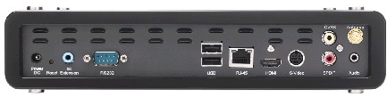
a.![]() Plug one yellow jack from the RCA video cable into the
CVBS
interface on the back panel of your DMP.
Plug one yellow jack from the RCA video cable into the
CVBS
interface on the back panel of your DMP.
b.![]() Connect the free end of this cable to the corresponding interface on your presentation system.
Connect the free end of this cable to the corresponding interface on your presentation system.
Step 2![]() Make connections for audio.
Make connections for audio.
a.![]() Plug the 3mm jack on the RCA audio cable into the
AUDIO
interface on the back panel of your DMP.
Plug the 3mm jack on the RCA audio cable into the
AUDIO
interface on the back panel of your DMP.
b.![]() Connect the free end of this cable to the corresponding interface on your presentation system.
Connect the free end of this cable to the corresponding interface on your presentation system.
Step 3![]() If the presentation system is not already turned on, turn it
On
now.
If the presentation system is not already turned on, turn it
On
now.
Step 4![]() Stop. You have completed this procedure.
Stop. You have completed this procedure.
Use RS-232 Signals to Control Presentation Systems
No international agency exists to tell all of the world’s video equipment manufacturers which commands and methods (such as RS-232) a presentation system must support. Likewise, no global authority exists to state exactly which hexadecimal string — if any — must invoke a particular command.
So when manufacturers implement RS-232 commands, they do so as they see fit. Thus, RS-232 command syntax differs among manufacturers and sometimes differs even among equipment models that share a manufacturer in common.
Tip Check the manufacturer’s product documentation for your LCD display to learn about its RS-232 support and syntax.
So, how is RS-232 useful to me?
Your digital signs run in the real world because your organization expects to tell someone something. But when you, the administrator, are half a world away from a sign, or even just a few buildings away, how can you be absolutely sure that your sign is doing anything — let alone everything — correctly?
• Is its power turned Off when it should be turned On?
• Is its audio muted during an exclusive musical performance?
- Does it ignore a valid video input signal while listening on some other, but disconnected, interface?
Meanwhile, how can you recognize and fix any such misconfiguration from miles away? Situations like these are perfect for RS-232, whose technology passes properly constructed “command-and-control” instructions through a DMP and into its attached presentation system.
A case in point: Cisco Digital Signs software can tell you automatically and in real-time which of your centrally managed Cisco LCD displays are turned On or Off. You can learn at a glance when one (or more) of these remote units is in the wrong power state, and then issue a simple command to correct the mistake. But even so, your ability to turn remote equipment On or Off so easily through the Internet is just one benefit of feeding RS-232 commands through a DMP to its attached LCD display.
This section includes these topics.
- Prepare Cisco Displays to Support RS-232 Syntax
- Bootstrap DMTech Displays to Enable Their RS-232 Support
- Bootstrap NEC Displays to Enable Their RS-232 Support
- Delete Equipment Settings That Use RS-232 Syntax
- Use RS-232 Signals to Control Presentation Systems
- Use RS-232 Syntax to Control Digital Signs
Prepare Cisco Displays to Support RS-232 Syntax
Note This material pertains to multiple Cisco LCD display models.
Individual Cisco LCD display models each support dozens of RS-232 commands, covering the range of their configurable features.
This topic explains various steps that you must complete before a Cisco LCD display supports RS-232 signaling for centralized management.
• Connect your Cisco LCD display to the DMP that will drive it.
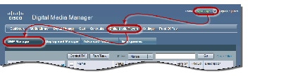
Step 2![]() Use one of these methods, at your discretion, to limit the scope of what the DMP List table shows to you.
Use one of these methods, at your discretion, to limit the scope of what the DMP List table shows to you.


Step 3![]() Click one DMP in the table to choose it exclusively.
Click one DMP in the table to choose it exclusively.

Use check boxes to choose multiple DMPs whose attached presentation systems are all identical.

Step 4![]() Click
Click , above the DMP List table.
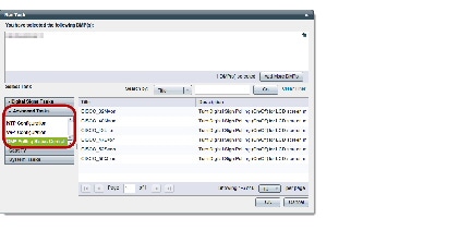
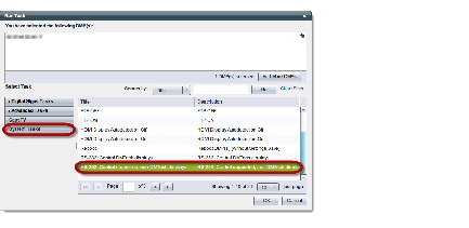
Step 5![]() Click
RS-232: Control supported, non-DMTech displays
in the System
Click
RS-232: Control supported, non-DMTech displays
in the System![]() Tasks drawer.
Tasks drawer.

A message loads under the DMP Manager tab, confirming that DMM received your submission.

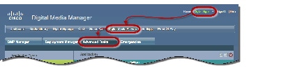
Step 7![]() Choose
Digital Media Players > Advanced Tasks > DMP Polling Status Control
.
Choose
Digital Media Players > Advanced Tasks > DMP Polling Status Control
.
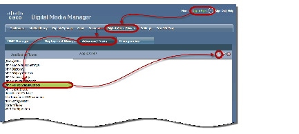
Step 8![]() Click
Click  Add New Application
.
Add New Application
.
a.![]() Choose your Cisco Professional Series LCD display model from the TV Type list.
Choose your Cisco Professional Series LCD display model from the TV Type list.

Note This variation of our standard TV Type list includes Cisco models exclusively. These are the only presentation system models whose electrical power On/Off state this Cisco DMS release can poll in real-time.
ALSO: Is your Cisco LCD display the 32-inch model? If so, see the ““ section, elsewhere in this procedure. It might be necessary for you to disable a feature that all other users enable.
b.![]() Choose
On
from the Polling list, and then click
Submit
.
Choose
On
from the Polling list, and then click
Submit
.
We generate a concise name for this application automatically. We are able to do this because your selections have already defined the purpose and scope of your new polling control application. Its generated name is always one of these:
After we show the name to you, your new polling control application is ready for use.
 , again.
Step 10![]() Click
DMP Polling Status Control
in the Advanced Tasks drawer.
Click
DMP Polling Status Control
in the Advanced Tasks drawer.
Step 11![]() Click the same “
=on
” application that you saved for your Cisco LCD model, and then click
OK
.
Click the same “
=on
” application that you saved for your Cisco LCD model, and then click
OK
.
A message loads under the DMP Manager tab, confirming that DMM received your submission.

Note As many as 5 minutes might pass before the LCD Status column updates its value to show the real-time power state of your Cisco LCD display. Ultimately, this value will say either “Display On” or “Display Off.” Until then, however, it will say “Not Set.”
Please check the next step in this procedure, however, to learn if another step is necessary here to configure your LCD Professional Series model. 
Step 12![]() Compensate, as needed, for model-specific exceptions to basic RS-232 setup.
Compensate, as needed, for model-specific exceptions to basic RS-232 setup.
|
Factory-default settings for this equipment save power by turning Off most of its support for remote management and polling. Almost any attempt to use such features can fail while the energy-saving settings remain in effect.1 So, before you can reliably manage or poll this equipment from Cisco DMS, YOU2 MUST explicitly prepare the RS-232 service for use. Later, at your discretion, you can either turn Off3 this support or leave it turned On4 continuously. a. Press Menu on the handheld remote control unit. Your LCD display shows its OSD menu.
b. |
|
|
|
|
Bootstrap DMTech Displays to Enable Their RS-232 Support
You can use our Digital Signs software to transmit instruction codes through your DMPs, and into their attached presentation systems.
Note We do not maintain or control the RS-232 commands for any third-party equipment. Please check the manufacturer documentation for your non-Cisco presentation systems to learn which RS-232 strings are engineered to manage them.

Step 2![]() Use one of these methods, at your discretion, to limit the scope of what the DMP List table shows to you.
Use one of these methods, at your discretion, to limit the scope of what the DMP List table shows to you.


Step 3![]() Click one DMP in the table to choose it exclusively.
Click one DMP in the table to choose it exclusively.

Use check boxes to choose multiple DMPs whose attached presentation systems are all identical.

Step 4![]() Click
Click , above the DMP List table.
Step 5![]() Click
RS-232: Control DMTech Displays
in the System
Click
RS-232: Control DMTech Displays
in the System![]() Tasks drawer.
Tasks drawer.
A message loads under the DMP Manager tab, confirming that DMM received your submission.

Step 7![]() Stop. You have completed this procedure.
Stop. You have completed this procedure.
Bootstrap NEC Displays to Enable Their RS-232 Support
You can use our Digital Signs software to transmit instruction codes through your DMPs, and into their attached presentation systems.
Note We do not maintain or control the RS-232 commands for any third-party equipment. Please check the manufacturer documentation for your non-Cisco presentation systems to learn which RS-232 strings are engineered to manage them.

Step 2![]() Use one of these methods, at your discretion, to limit the scope of what the DMP List table shows to you.
Use one of these methods, at your discretion, to limit the scope of what the DMP List table shows to you.


Step 3![]() Click one DMP in the table to choose it exclusively.
Click one DMP in the table to choose it exclusively.

Use check boxes to choose multiple DMPs whose attached presentation systems are all identical.

Step 4![]() Click
Click , above the DMP List table.
Step 5![]() Click
RS-232: Control supported, non-DMTech displays
in the System
Click
RS-232: Control supported, non-DMTech displays
in the System![]() Tasks drawer.
Tasks drawer.
A message loads under the DMP Manager tab, confirming that DMM received your submission.

Step 7![]() Stop. You have completed this procedure.
Stop. You have completed this procedure.
Use RS-232 Syntax to Control Digital Signs
You can add and edit RS-232 commands that operate LCD displays or other presentation system types.
- Prepare your displays for centralized management via RS-232 commands.
- Activate RS-232 command access for your displays.

Step 2![]() Click
System
Click
System![]() Tasks
in the Application Types list.
Tasks
in the Application Types list.
Step 3![]() Do one of the following.
Do one of the following.
 Add New Application
.
Add New Application
. Edit Application
.
Edit Application
.For example, the hexadecimal strings in Table 16-1 convey many of the RS-232 commands that you can send in this way to a Cisco LCD Professional Series display.
|
5.An image with a colorfulness value of zero percent is grayscale, while the same image with a colorfulness value of 100 percent has vivid colors. 6.The display ignores its handheld remote control but still responds to other commands. 7.The display ignores its built-in buttons but still responds to other commands. 8.Control the display exclusively through your DMP. Neither the handheld remote control nor buttons on the display can override your off-site management. |
Step 4![]() Set other, optional values as needed.
Set other, optional values as needed.
Step 5![]() Click
Submit
to save your work, so that you might someday use it.
Click
Submit
to save your work, so that you might someday use it.
OR
Click
Cancel
to discard your work.
Step 6![]() Stop. You have completed this procedure.
Stop. You have completed this procedure.
-
Would you like to
delete
a saved command?
Proceed to the “Delete Equipment Settings That Use RS-232 Syntax” section.
Delete Equipment Settings That Use RS-232 Syntax
You can delete any of your named and saved RS-232 command strings.
Step 2![]() Click
System
Click
System![]() Tasks
in the Application Types list.
Tasks
in the Application Types list.
Step 3![]() Find your editing target in the Applications table.
Find your editing target in the Applications table.
Step 4![]() Click its named row in the Applications table.
Click its named row in the Applications table.
Step 5![]() Click
Click  Delete Application
.
Delete Application
.
Step 6![]() Click
Submit
to commit this deletion.
Click
Submit
to commit this deletion.
OR
Click
Cancel
to abandon this deletion.
Step 7![]() Stop. You have completed this procedure.
Stop. You have completed this procedure.

Prepare a 40- or 52-inch Cisco LCD to Support Centralized Management through DVI
Note Only our 40-inch and 52-inch LCD display models support DVI connections.
When you use an HDMI cable or a DVI cable to connect your DMP to a 40- or 52-inch Cisco LCD display, you can use Digital Signs to centrally manage the LCD display.
When unmodified HDMI is the connection type from a DMP to either of these display models, centralized management from DMM works immediately, without any prerequisites. However, when you combine HDMI with a DVI adapter, you must complete a simple task at the physical installation site for your display before you can start to centrally manage it.
OR
Press Menu on the LCD display front panel.
Step 2![]() Choose
Input > Source List > DVI
, and then press
Enter
.
Choose
Input > Source List > DVI
, and then press
Enter
.
Step 3![]() Choose
Input > Edit Name > DVI > HD STB
, and then press
Enter
.
Choose
Input > Edit Name > DVI > HD STB
, and then press
Enter
.
Step 4![]() Stop. You have completed this procedure.
Stop. You have completed this procedure.

Activate or Deactivate HDMI Autodetection
OR
Deploy the System
Step 2![]() Stop. You have completed this procedure.
Stop. You have completed this procedure.
Activate or Deactivate Resolution Autodetection
• Activate HDMI autodetection.
OR
Deploy the System
Step 2![]() Stop. You have completed this procedure.
Stop. You have completed this procedure.
Use Predefined Tasks to Configure and Manage Equipment
• Define or Edit DMP Output Settings for A/V
Define or Edit DMP Output Settings for A/V
You can configure the audio and video signals that DMPs send to their attached presentation systems.

Step 2![]() Click
DMP Audio/Video Settings
in the Application Types list.
Click
DMP Audio/Video Settings
in the Application Types list.
Step 3![]() Do one of the following.
Do one of the following.
 Add New Application
.
Add New Application
.

 Edit Application
.
Edit Application
.
Step 4![]() Click
Submit
to save your work, so that you might someday use it.
Click
Submit
to save your work, so that you might someday use it.
OR
Click
Cancel
to discard your work.
Step 5![]() Stop. You have completed this procedure.
Stop. You have completed this procedure.
Delete DMP Output Settings for A/V
You can delete any of your named and saved settings for DMP audio and video output.

Step 2![]() Click
DMP Audio/Video Settings
in the Application Types list.
Click
DMP Audio/Video Settings
in the Application Types list.
Step 3![]() Find your deletion target in the Applications table.
Find your deletion target in the Applications table.
Step 4![]() Click its named row in the Applications table.
Click its named row in the Applications table.
Step 5![]() Click
Click  Delete Application
.
Delete Application
.
Step 6![]() Click
Submit
to commit this deletion.
Click
Submit
to commit this deletion.
OR
Click
Cancel
to abandon this deletion.
Step 7![]() Stop. You have completed this procedure.
Stop. You have completed this procedure.
Use Simple Menus to Control A/V Settings
You can define and save a customized bundle of device configuration settings for certain popular presentation system models. We provide this option for models that pass our tests for DMP compatibility.
Step 1![]() Do one of the following.
Do one of the following.
|
a. Choose Digital Media Players > DMP Manager . 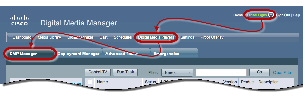
b. 
c. 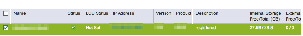
d.
e. |
|
|
a. Choose Digital Media Players > Advanced Tasks . 
b.
c. The page is refreshed so that you can choose options and enter values.
d. |
 , above the DMP List table..
 Add New Application
.
Add New Application
.
Step 2![]() Choose your display’s make and model from the TV Type list.
Choose your display’s make and model from the TV Type list.

Note We provide preconfigured tasks for only the presentation system models that pass our tests for DMP compatibility.
Step 3![]() Enter a name for the bundle of device configuration settings that you are about to define.
Enter a name for the bundle of device configuration settings that you are about to define.
Step 4![]() Set values for video attributes.
Set values for video attributes.
Step 5![]() Set values for audio attributes.
Set values for audio attributes.
Step 6![]() Set other, optional values as needed.
Set other, optional values as needed.
Step 7![]() Click
Submit
to save your work, so that you might someday use it.
Click
Submit
to save your work, so that you might someday use it.
OR
Click
Cancel
to discard your work.
Step 8![]() Stop. You have completed this procedure.
Stop. You have completed this procedure.
-
Would you like to
edit
what you saved?
Proceed to the “Edit A/V Settings That You Chose from Menus” section. -
Would you like to
delete
what you saved?
Proceed to the “Delete A/V Settings That You Chose from Menus” section.
• Prepare a 40- or 52-inch Cisco LCD to Support Centralized Management through DVI
• Elements to Choose A/V Settings from Menus
• Elements to Activate RS-232 for Supported LCD Display Brands (except DMTech)
Edit A/V Settings That You Chose from Menus
You can edit any of your named and saved RS-232 command string bundles.

Step 2![]() Click
DMP Display Controls
in the Application Types list.
Click
DMP Display Controls
in the Application Types list.
Step 3![]() Find your editing target in the Applications table.
Find your editing target in the Applications table.
Step 4![]() Click its named row in the Applications table.
Click its named row in the Applications table.
Step 5![]() Click
Click  Edit Application
.
Edit Application
.
The page is refreshed so that you can choose options and enter values.
Step 7![]() Click
Submit
to save your work, so that you might someday use it.
Click
Submit
to save your work, so that you might someday use it.
OR
Click
Cancel
to discard your work.
Step 8![]() Stop. You have completed this procedure.
Stop. You have completed this procedure.
•
Would you like to
delete
what you edited?
Proceed to the “Delete A/V Settings That You Chose from Menus” section.
• Prepare a 40- or 52-inch Cisco LCD to Support Centralized Management through DVI
Delete A/V Settings That You Chose from Menus
You can delete any of your named and saved RS-232 command strings.

Step 2![]() Click
DMP Display Controls
in the Application Types list.
Click
DMP Display Controls
in the Application Types list.
Step 3![]() Find your deletion target in the Applications table.
Find your deletion target in the Applications table.
Step 4![]() Click its named row in the Applications table.
Click its named row in the Applications table.
Step 5![]() Click
Click  Delete Application
.
Delete Application
.
Step 6![]() Click
Submit
to commit this deletion.
Click
Submit
to commit this deletion.
OR
Click
Cancel
to abandon this deletion.
Step 7![]() Stop. You have completed this procedure.
Stop. You have completed this procedure.
Reference
- Video and Audio Signal Interfaces
- Supported Touchscreen Drivers
- Software UI and Field Reference Tables
- FAQs and Troubleshooting
Video and Audio Signal Interfaces


|
9.Backward-compatible to HDMI 1.1. 10.Use an S-Video signal cable with a YPbPr-to-S-Video adapter to transmit and receive YPbPr data signals. 11.There is no Composite CVBS connector on a DMP 4310G. Its YPbPr/S-Video connector supports Composite CVBS via an S-Video-to-Composite adapter. 12.Stereo audio output, irrespective of the cable type for video output. |
Supported Touchscreen Drivers
Software UI and Field Reference Tables
• Elements to Choose A/V Settings from Menus
• Elements to Configure DMP Audio/Video Settings
• Elements to Control HDMI Display Autodetection
• Elements to Control Screen Resolution Autodetection
• Elements to Activate RS-232 for Supported LCD Display Brands (except DMTech)
Elements to Choose A/V Settings from Menus
- Digital Media Players > DMP Manager > Control TV
- Digital Media Players > Advanced Tasks > DMP Audio/Video Settings
Elements to Configure DMP Audio/Video Settings
Digital Media Players > Advanced Tasks > DMP Audio/Video Settings
Elements to Control HDMI Display Autodetection
Digital Media Players > Advanced Tasks > System Tasks > HDMI Display Autodetection...
Elements to Control Screen Resolution Autodetection
Digital Media Players > Advanced Tasks > System Tasks > Screen Resolution Autodetection...
Elements to Activate RS-232 for Supported LCD Display Brands (except DMTech)
Tip Before you pass RS-232 commands through your DMPs and to your DMP displays, first confirm that each DMP is connected to its display by a signal cable that supports RS-232 signals. Otherwise, your displays will never receive the commands that you define for them.
Digital Media Players > Advanced Tasks > System Tasks > RS-232: Control Supported, Non-DMTech Displays
Elements to Activate RS-232 for LCD Displays by DMTech
Tip Before you pass RS-232 commands through your DMPs and to your DMP displays, first confirm that each DMP is connected to its display by a signal cable that supports RS-232 signals. Otherwise, your displays will never receive the commands that you define for them.
Digital Media Players > Advanced Tasks > System Tasks > RS-232: Control DMTech Displays
FAQs About Cleaning and Maintenance
• How should I clean and maintain a Professional Series display?
Q. How should I clean and maintain a Professional Series display?
For cleaning and maintenance guidelines, see the Safety Instructions section called “Cleaning the Display, Its Plug, and Its Outlet Safely” in User Guide for Cisco LCD Professional Series Displays on Cisco.com.
FAQs About Daily Operation
• How long does display autodetection take?
• Why might display autodetection fail?
Q. How long does display autodetection take?
Autodetection takes less than 8 seconds in most cases and less than 2 seconds in some cases.
Q. Why might display autodetection fail?
The display autodetection feature fails unless you use an HDMI signal cable (with or without a DVI adapter) to connect a presentation system to your DMP.
FAQs About RS-232
• Why does my DMP 4400G run very slowly while its RS-232 features are enabled?
Q. Why does my DMP 4400G run very slowly while its RS-232 features are enabled?
The likeliest explanation is that your signal cable is faulty. Try substituting the equivalent cable from a DMP that operates as expected when RS-232 features are enabled. If doing this has no effect, restore your DMP to its factory-default settings and then configure it once more to support RS-232.
FAQs About Touchscreens
• What should I do when a message states that my touchscreen must download a characterization file?
• When is it necessary to repeat the calibration of a touchscreen?
• What can cause a properly calibrated touchscreen to operate as if it is not calibrated?
Q. What should I do when a message states that my touchscreen must download a characterization file?
Do not disturb or interrupt the automated process. It occurs only once, and takes approximately 10 minutes to finish. When it is finished, your touchscreen will clear the message automatically.
Q. When is it necessary to repeat the calibration of a touchscreen?
You must repeat this calibration whenever you:
Q. What can cause a properly calibrated touchscreen to operate as if it is not calibrated?
If this happens to you, unplug the serial cable (or USB cable) that connects this touchscreen to your DMP. Then, plug that cable back in again.
FAQs About Product Quality
• Why are some pixels unexpectedly bright, or black?
Q. Why are some pixels unexpectedly bright, or black?
Cisco LCD displays use advanced semiconductor technology with extremely high precision. Nonetheless, the red, green, blue and white pixels might seem unexpectedly bright sometimes, or you might notice some black pixels. This is not the result of low quality or a malfunction and you can continue to use your display without incident.
Troubleshoot Cisco Professional Series LCD Displays
Troubleshoot the Power Indicator
Problem The screen is blank AND the power indicator is off.
Solution Ensure that the power cord is firmly connected and the display is turned on.
Problem The power indicator blinks.
Solution Wait for less than 1 minute. The display is saving changes made to its settings.
Troubleshoot Image Quality
Problem A message states, “Check Signal Cable.”
Problem The image rolls vertically.
Solution Make sure that the signal cable is securely connected.
Problem The image is intermittently black (CSCtw78742; CSCts83613).
Solution Avoid incompatible combinations.
- Have you used a DVI connector while our HDMI resolution autodetect feature was enabled on your DMP? And then, was the reported resolution called “1920 x 1080?” If so, you must disable the autodetection feature. Cisco DMP models support DVI connections only in combination with VESA-standard resolution values — and VESA standards do not include “1920 x 1080.” Instead, their equivalent is called “VESA_1080p.” You must choose and apply this resolution value manually.
- Do not enable HDMI autodetection with a display whose resolution is “DVI_1920p.”
- Disable our HDMI resolution autodetect feature on your DMP when it reports that any 1080p presentation system characterizes its resolution as “VESA_1080p.” Then, impose the resolution value manually that DMPs use: “HDMI_1080p.”
Solution Try these possible workarounds.
• Run Frequency Coarse and Fine tuning.
• Turn Off the display, remove its accessories and signal cables, and then turn it On again.
• Set the resolution and frequency to the recommended ranges.
Problem The image is too light OR too dark.
Solution Adjust the brightness and contrast.
Problem Colors are not consistent, OR shadows are too dark, OR white areas are too white.
Troubleshoot Audio Quality
Problem Sound is too quiet OR is not audible.
Solution Check the volume level.
Troubleshoot the Handheld Remote Control Unit
Problem Buttons do not respond.
• Battery polarities (+/-).
• If batteries have lost their charge.
• If the power is turned On.
• If the power cord is connected securely.
• If a fluorescent or neon lamp is turned On nearby.
 Feedback