Replacing a Drive
You can remove and install some drives without removing the compute node from the chassis. All drives have front-facing access, and they can be removed and inserted by using the ejector handles.
The SAS/SATA or NVMe drives supported in this compute node come with the drive sled attached. Spare drive sleds are not available.
Before upgrading or adding a drive to a running compute node, check the service profile through Cisco UCS management software and make sure the new hardware configuration will be within the parameters allowed by the management software.
 Caution |
To prevent ESD damage, wear grounding wrist straps during these procedures. |
NVMe SSD Requirements and Restrictions
For 2.5-inch NVMe SSDs, be aware of the following:
-
NVMe 2.5 SSDs support booting only in UEFI mode. Legacy boot is not supported.
UEFI boot mode can be configured through Cisco UCS management software.
-
NVME U.3 SSDs connect to the RAID controller so RAID is supported for these drives.
-
UEFI boot is supported in all supported operating systems.
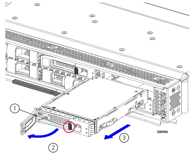
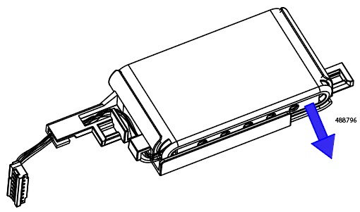
Removing a Drive
Use this task to remove a SAS/SATA or NVMe drive from the compute node.
Caution |
Do not operate the system with an empty drive bay. If you remove a drive, you must reinsert a drive or cover the empty drive bay with a drive blank. |
Procedure
|
Step 1 |
Push the release button to open the ejector, and then pull the drive from its slot.
|
||
|
Step 2 |
Place the drive on an antistatic mat or antistatic foam if you are not immediately reinstalling it in another compute node. |
||
|
Step 3 |
Install a drive blanking panel to maintain proper airflow and keep dust out of the drive bay if the drive bay will remain empty. |
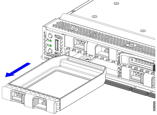
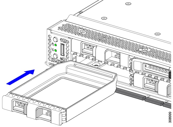
What to do next
Cover the empty drive bay. Choose the appropriate option:
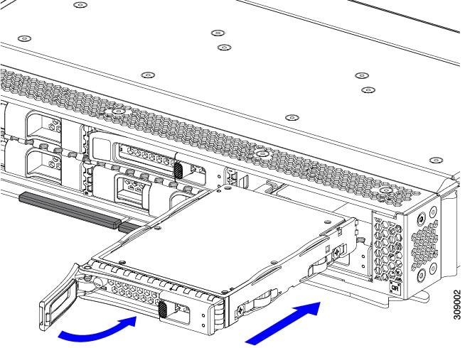
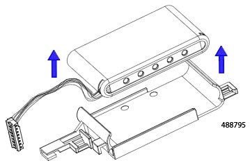
Installing a Drive
Caution |
For hot installation of drives, after the original drive is removed, you must wait for 20 seconds before installing a drive. Failure to allow this 20-second wait period causes the Cisco UCS management software to display incorrect drive inventory information. If incorrect drive information is displayed, remove the affected drive(s), wait for 20 seconds, then reinstall them. |
To install a SAS/SATA or NVMe drive in the compute node, follow this procedure:
Procedure
|
Step 1 |
Place the drive ejector into the open position by pushing the release button. |
|
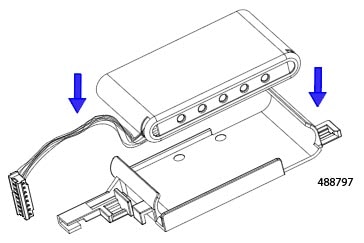
Step 2 |
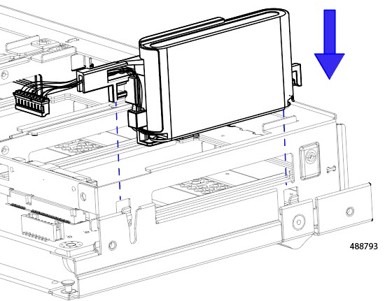
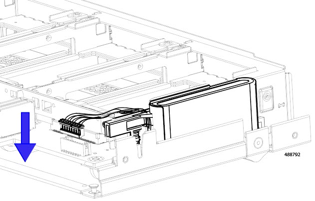
Gently slide the drive into the empty drive bay until it seats into place. |
|
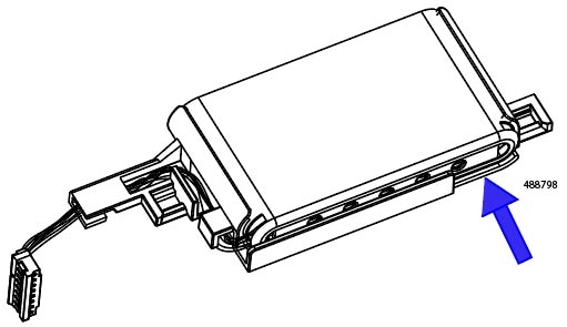
Step 3 |
Push the drive ejector into the closed position. You should feel the ejector click into place when it is in the closed position.
|

 Feedback