Overview
This chapter provides an overview of the Cisco UCS S3260 storage server.
For information about the server nodes that are supported in this system, see the service note for your server node:
- Cisco UCS C3X60 M3 Server Node For Cisco UCS S3260 System Service Note
- Cisco UCS C3X60 M4 Server Node For Cisco UCS S3260 System Service Note
- Cisco UCS S3260 M5 Server Node For Cisco UCS S3260 System Service Note
For instructions on migrating from C3X60 M4 server nodes to S3260 M5 server nodes, see Upgrading to Cisco UCS S3260 System With S3260 M5 Server Nodes.
Front Panel Features
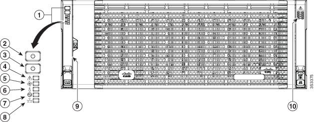
Figure 1-1 shows the front panel features of the system. The system is shown with the removable front bezel installed. See Front-Panel LEDs for definitions of LED states.
Figure 1-1 Front Panel Features
|
|
|
||
|
|
|
||
|
|
|
||
|
|
|
||
|
|
|
Rear Panel Features
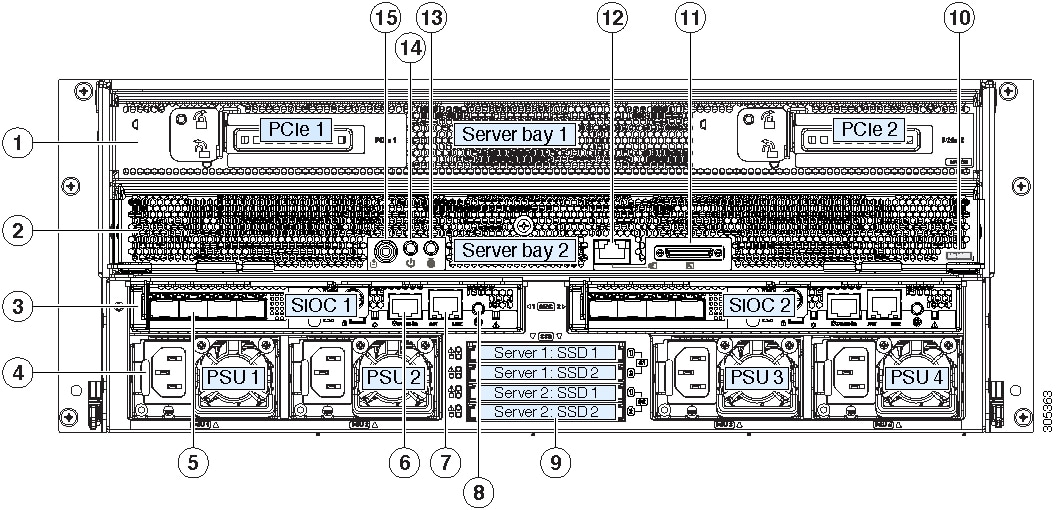
Figure 1-2 Rear Panel Features (S3260 M5 Server Node With I/O Expander and Version 03 SIOCs Shown)
Replaceable Component Locations
This section contains the following topics:
- Replaceable Components Inside the Main Chassis
- Components Inside the C3X60 Server Node
- Components Inside the I/O Expander
- Components Inside the System I/O Controller
Replaceable Components Inside the Main Chassis
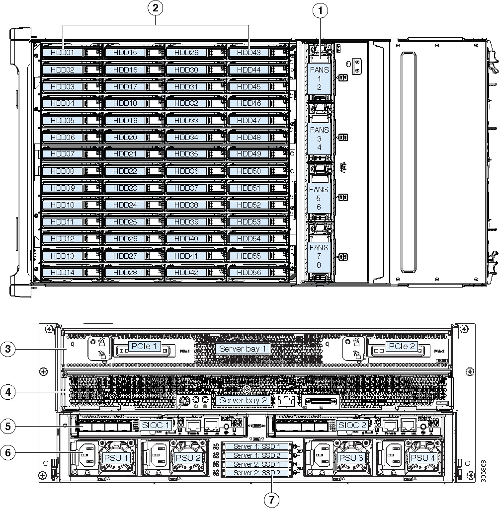
This section shows the locations of the replaceable components that are inside the main chassis. Some components are accessible from the rear panel and others are accessible by opening the top covers.
The top view of the system in Figure 1-3 shows the top covers open.

Note![]() The internal drives and cooling fans in the system are hot-swappable and are accessed by opening the top covers. When you rack and cable the system, be sure to allow enough slack in the power cords and other cables so that the system can be pulled out on the slide rails far enough to allow clearance for opening the top covers.
The internal drives and cooling fans in the system are hot-swappable and are accessed by opening the top covers. When you rack and cable the system, be sure to allow enough slack in the power cords and other cables so that the system can be pulled out on the slide rails far enough to allow clearance for opening the top covers.
Figure 1-3 Replaceable Components Inside the Main Chassis (Top View and Rear View)
|
|
|
||
|
|
Top-loading drive bays (up to 56 3.5-inch HDDs or SSDs, hot-swappable) |
|
|
|
|
|
||
|
|
|
Components Inside the C3X60 Server Node
For the locations of the replaceable components that are inside a server node, see the service note for your server node:
Components Inside the I/O Expander
The C3X60 M4 or S3260 M5 server node might include an optional I/O expander that attaches to the top of the server node. For the locations of the replaceable components that are inside an I/O expander, see the service note for your server node:
Components Inside the System I/O Controller
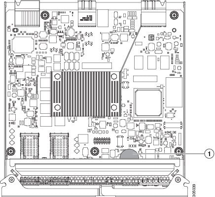
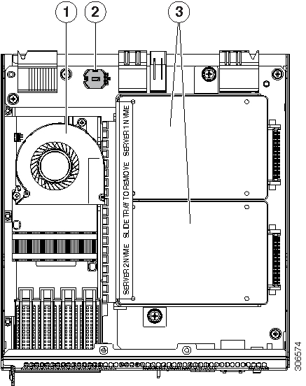
This section shows the locations of the replaceable components that are inside the system I/O controller (SIOC), which is accessible from the rear of the chassis.
- The Version 02 SIOC (UCSC-S3260-SIOC) uses an integrated Cisco UCS VIC 1300 Series chip on-board, so there is no removable adapter card. The only replaceable component is an RTC battery.
- The Version 03 SIOC (UCS-S3260-PCISIOC) uses a removable PCIe-style adapter card (half-height, half-length, Gen-3, x8 lane). It also supports up to two 2.5-inch NVMe SSDs and an RTC battery.
Note![]() The Version 03 SIOC is supported only with S3260 M5 server node. It is not supported with earlier server nodes.
The Version 03 SIOC is supported only with S3260 M5 server node. It is not supported with earlier server nodes.
Figure 1-4 Replaceable Components Inside the Version 02 SIOC (UCSC-S3260-SIOC)
|
|
|
Figure 1-5 Replaceable Components Inside the Version 03 SIOC (UCS-S3260-PCISIOC)
|
|
|
Up to two 2.5-inch NVMe SSDs plug into two horizontal sockets (both SSDs are secured to a single drive sled). |
|
|
|
|
Overview of Cisco UCS S3260 Architecture
This section describes the high-level organization of the system’s management and data architecture, in relation to the hardware.
Management Architecture
The system uses a chassis management controller (CMC) to manage the server nodes. Each system I/O controller (SIOC) module contains an onboard CMC. If you have two SIOCs, the two CMCs act in an active/standby organization. The CMC in the SIOC that you log into with the Cisco IMC interface becomes the active CMC and it allows you to manage the board management controllers (BMCs) in both server nodes.
When you connect to the system to manage the server nodes’ BMCs via the Cisco IMC interface, you physically connect to the ports on a SIOC. When you log into the Cisco IMC interface, you use a system management IP address. Each CMC and each BMC also has an IP address for internal communication.
All user interfaces run only on the active CMC. Configuration changes are automatically synchronized between the active and standby CMCs.
The active CMC will fail over to the standby CMC when any of the following conditions occur:
- The active CMC is rebooted or fails.
- The SIOC with active CMC is removed.
- Network connectivity is lost on the active CMC.
Figure 1-6 shows an example of a system with two server nodes in which there is a physical connection to the QSFP ports on both SIOCs, but the SIOC 1 CMC is the active CMC that manages both server nodes.
Figure 1-6 Management Architecture
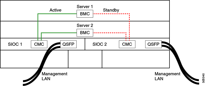
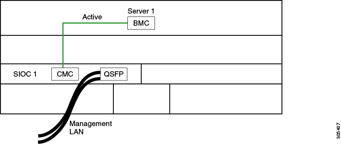
Figure 1-6 shows an example of a system with one server node and one SIOC. In this case, there is no standby or failover.
Figure 1-7 Management Architecture
Data Architecture
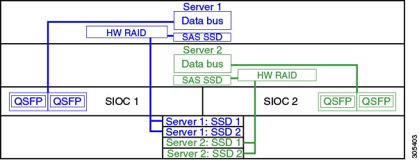
The data plane architecture has different associations between components than the management plane. The diagram shown in Figure 1-8 illustrates the following associations for a dual-server system:
- The data bus in server node 1 connects through SIOC 1.
- The data bus in server node 2 connects through SIOC 2.
- Server 1 SSDs 1 and 2 can be controlled by a RAID controller card in server node 1.
- Server 2 SSDs 1 and 2 can be controlled by a RAID controller card in server node 2.
Figure 1-8 Data Architecture in a Dual-Server System
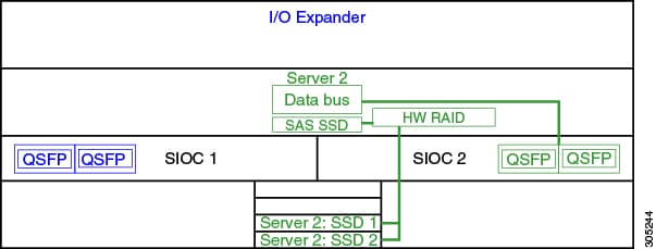
The diagram shown in Figure 1-9 illustrates the following associations for a single-server system:
- The data bus in server node 2 connects through SIOC 2.
- Server 2 SSDs 1 and 2 can be controlled by a RAID controller card in server node 2.
Figure 1-9 Data Architecture in a Single-Server System With I/O Expander
System Features Overview
Table 1-1 lists the features of the system.
|
|
The system has the following storage options:
|
|
The system supports up to two storage controllers:
Note |
|
The supercap battery backup mounts to the RAID controller card. The dual RAID controller used in M5 server nodes uses two supercap units. |
|
The system can have one or two system I/O controllers (SIOCs). These provide rear-panel management and data connectivity. The server nodes each have one rear-panel KVM connector that can be used with a KVM cable, which provides two USB, one VGA DB-15, and one serial DB-9 connector. |
|
Four power supplies, hot-swappable and redundant as 3+1. All installed power supplies must be identical. |
|
Four internal fan modules that pull front-to-rear cooling, hot-swappable. Each fan module contains two fans. |
|
Cisco Integrated Management Controller (Cisco IMC) firmware. Depending on your NIC mode settings, the Cisco IMC can be accessed through the See also Management Architecture. |
 Feedback