Installing the System
This chapter describes how to install the system, and it includes the following sections:
- Unpacking and Inspecting the System
- Preparing for System Installation
- Installing the System in a Rack
- Initial System Setup
- NIC Modes and NIC Redundancy Settings
- System BIOS and Cisco IMC Firmware

Note![]() Before you install, operate, or service a system, review the Regulatory Compliance and Safety Information for Cisco UCS S-Series Servers for important safety information.
Before you install, operate, or service a system, review the Regulatory Compliance and Safety Information for Cisco UCS S-Series Servers for important safety information.

Warning![]() IMPORTANT SAFETY INSTRUCTIONS
IMPORTANT SAFETY INSTRUCTIONS
This warning symbol means danger. You are in a situation that could cause bodily injury. Before you work on any equipment, be aware of the hazards involved with electrical circuitry and be familiar with standard practices for preventing accidents. Use the statement number provided at the end of each warning to locate its translation in the translated safety warnings that accompanied this device.
Statement 1071
Unpacking and Inspecting the System

Note![]() The chassis is thoroughly inspected before shipment. If any damage occurred during transportation or any items are missing, contact your customer service representative immediately.
The chassis is thoroughly inspected before shipment. If any damage occurred during transportation or any items are missing, contact your customer service representative immediately.
Step 1![]() Remove the system from its cardboard container and save all packaging material.
Remove the system from its cardboard container and save all packaging material.
Step 2![]() Compare the shipment to the equipment list provided by your customer service representative. Verify that you have all items.
Compare the shipment to the equipment list provided by your customer service representative. Verify that you have all items.
Step 3![]() Check for damage and report any discrepancies or damage to your customer service representative. Have the following information ready:
Check for damage and report any discrepancies or damage to your customer service representative. Have the following information ready:
- Invoice number of shipper (see the packing slip)
- Model and serial number of the damaged unit
- Description of damage
- Effect of damage on the installation
Preparing for System Installation
This section provides information about preparing for system installation, and it includes the following topics:
Installation Guidelines
Warning![]() To prevent the system from overheating, do not operate it in an area that exceeds the maximum recommended ambient temperature of: 35° C (95° F).
To prevent the system from overheating, do not operate it in an area that exceeds the maximum recommended ambient temperature of: 35° C (95° F).
Statement 1047
Warning![]() The plug-socket combination must be accessible at all times, because it serves as the main disconnecting device.
The plug-socket combination must be accessible at all times, because it serves as the main disconnecting device.
Statement 1019
Warning![]() This product relies on the building’s installation for short-circuit (overcurrent) protection. Ensure that the protective device is rated not greater than: 250 V, 15 A.
This product relies on the building’s installation for short-circuit (overcurrent) protection. Ensure that the protective device is rated not greater than: 250 V, 15 A.
Statement 1005
Warning![]() Installation of the equipment must comply with local and national electrical codes.
Installation of the equipment must comply with local and national electrical codes.
Statement 1074
When you are installing a system, use the following guidelines:
- Plan your site configuration and prepare the site before installing the system. See the Cisco UCS Site Preparation Guide for the recommended site planning tasks.
- Ensure that there is adequate space around the system to allow for servicing the system and for adequate airflow. The airflow in this system is from front to back.
- Ensure that the air-conditioning meets the thermal requirements listed in the System Specifications.
- Ensure that the cabinet or rack meets the requirements listed in the Rack Requirements.
- Ensure that the site power meets the power requirements listed in the System Specifications. You can use an uninterruptible power supply (UPS), if available, to protect against power failures.
Rack Requirements
This section provides the requirements for the standard open racks, assuming an external ambient air temperature range of 41°F to 95°F (5°C to 35°C).
The rack must be of the following type:
- A standard 19-in. (48.3-cm) wide, four-post EIA rack, with mounting posts that conform to English universal hole spacing, per section 1 of ANSI/EIA-310-D-1992.
- The rack post holes can be square 0.38-inch (9.6 mm), round 0.28-inch (7.1 mm), #12-24 UNC, or #10-32 UNC when you use the supplied slide rails.
- The minimum vertical rack space per system must be four RUs, equal to 7 in. (17.78 cm).
- There must be a minimum of 48 inches clearance at the front of the rack.
Equipment Requirements
The slide rails supplied by Cisco Systems for this system do not require tools for installation if you install them in a rack that has square 0.38-inch (9.6 mm), round 0.28-inch (7.1 mm), or #12-24 UNC threaded holes.
Slide Rail Adjustment Range
The slide rails for this system have an adjustment range of 26 to 36 inches (660 to 914 mm).
Cable Management Arm Dimensions
The optional cable management arm (CMA) adds additional length requirements:
Installing the System in a Rack
This section contains the following topics:
- Installing the Slide Rails
- Installing the Cable Management Arm (Optional)
- Reversing the Cable Management Arm (Optional)
Warning![]() To prevent bodily injury when mounting or servicing this unit in a rack, you must take special precautions to ensure that the system remains stable. The following guidelines are provided to ensure your safety: This unit should be mounted at the bottom of the rack if it is the only unit in the rack.
To prevent bodily injury when mounting or servicing this unit in a rack, you must take special precautions to ensure that the system remains stable. The following guidelines are provided to ensure your safety: This unit should be mounted at the bottom of the rack if it is the only unit in the rack.
When mounting this unit in a partially filled rack, load the rack from the bottom to the top with the heaviest component at the bottom of the rack. If the rack is provided with stabilizing devices, install the stabilizers before mounting or servicing the unit in the rack. Statement 1006
Installing the Slide Rails
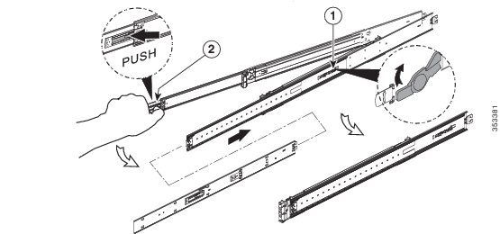
Step 1![]() Remove the inner rail from the slide-rail assembly (see Figure 2-1):
Remove the inner rail from the slide-rail assembly (see Figure 2-1):
a.![]() Slide out the intermediate and inner slide rails until they click and lock in the fully open position.
Slide out the intermediate and inner slide rails until they click and lock in the fully open position.
b.![]() Hold down the inner rail release clip and at the same time, pull the inner rail free from the assembly.
Hold down the inner rail release clip and at the same time, pull the inner rail free from the assembly.
c.![]() Push down the rail release latch while you collapse the intermediate rail back into the rail assembly for safety.
Push down the rail release latch while you collapse the intermediate rail back into the rail assembly for safety.
Figure 2-1 Removing the Inner Rail From the Assembly
|
|
|
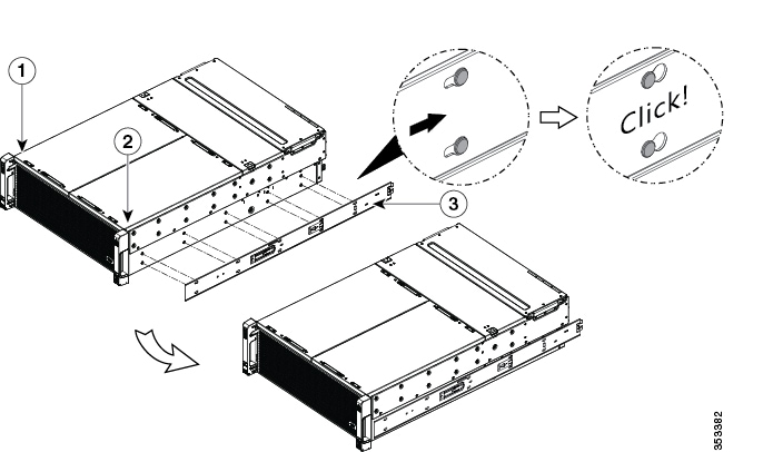
Step 2![]() Attach the inner rails to the sides of the chassis (see Figure 2-2):
Attach the inner rails to the sides of the chassis (see Figure 2-2):
Note![]() The inner rails are not identical: there is a left rail and a right rail (as viewed from the chassis front). The inner rails are marked with “L” for left or “R” for right.
The inner rails are not identical: there is a left rail and a right rail (as viewed from the chassis front). The inner rails are marked with “L” for left or “R” for right.
a.![]() Align the left inner rail marked “L” with the left side of the chassis (as viewed from the front). Align the 10 keyed slots in the rail with the 10 pegs on the side of the chassis.
Align the left inner rail marked “L” with the left side of the chassis (as viewed from the front). Align the 10 keyed slots in the rail with the 10 pegs on the side of the chassis.
b.![]() Set the keyed slots over the pegs, then slide the rail toward the rear to lock it in place on the pegs.
Set the keyed slots over the pegs, then slide the rail toward the rear to lock it in place on the pegs.
c.![]() Install the right inner rail marked “R” to the right side of the chassis (as viewed from the front).
Install the right inner rail marked “R” to the right side of the chassis (as viewed from the front).
Figure 2-2 Attaching Inner Rail to Sides of the Chassis
|
|
|
||
|
|
|
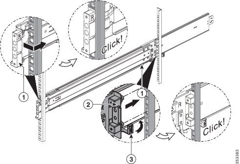
Step 3![]() Install the slide rails into the rack (see Figure 2-3):
Install the slide rails into the rack (see Figure 2-3):
Note![]() The slide rail assemblies are not identical; there is a left rail and a right rail (as viewed from the rack front). The assemblies are marked with “L” for left or “R” for right.
The slide rail assemblies are not identical; there is a left rail and a right rail (as viewed from the rack front). The assemblies are marked with “L” for left or “R” for right.
a.![]() Align the front end of the left-side slide-rail assembly (marked “L”) with the left-front rack-post (as you face the front of the rack).
Align the front end of the left-side slide-rail assembly (marked “L”) with the left-front rack-post (as you face the front of the rack).
The slide rail front-end wraps around the outside of the rack post and the mounting pegs enter the rack-post holes from the outside-front.
The bottom of the slide rail assembly lines up with the intended bottom of the rack unit (RU).
b.![]() Push the front mounting pegs into the rack-post holes until you hear them click and lock.
Push the front mounting pegs into the rack-post holes until you hear them click and lock.
c.![]() Adjust the slide-rail length until it reaches the rear rack post perfectly level.
Adjust the slide-rail length until it reaches the rear rack post perfectly level.
Note![]() Ensure that the rail is perfectly level and that the same height rack-post holes are used in the front and rear rack posts.
Ensure that the rail is perfectly level and that the same height rack-post holes are used in the front and rear rack posts.
d.![]() Hold open the rear-peg spring latch, then push the rear mounting pegs into the rear rack-post-holes.
Hold open the rear-peg spring latch, then push the rear mounting pegs into the rear rack-post-holes.
The rear mounting pegs enter the rear rack-post holes from the inside of the rack post.
e.![]() Release the rear-peg spring latch to lock the rear pegs in place.
Release the rear-peg spring latch to lock the rear pegs in place.
f.![]() Attach the right-side slide-rail assembly (marked “R”) to the right side of the rack.
Attach the right-side slide-rail assembly (marked “R”) to the right side of the rack.
g.![]() Ensure that the two slide-rail assemblies are at the same height and are level front-to-back. Also ensure that the right-side and left-side assemblies are correctly installed to the corresponding left or right rack posts, as you face the rack front.
Ensure that the two slide-rail assemblies are at the same height and are level front-to-back. Also ensure that the right-side and left-side assemblies are correctly installed to the corresponding left or right rack posts, as you face the rack front.
Figure 2-3 Attaching Rail Assembly to the Rack Post
|
|
Front mounting pegs, entering rack-post holes from the outside front |
|
|
|
|
Rear mounting pegs, entering rack post-holes from inside rear |
|
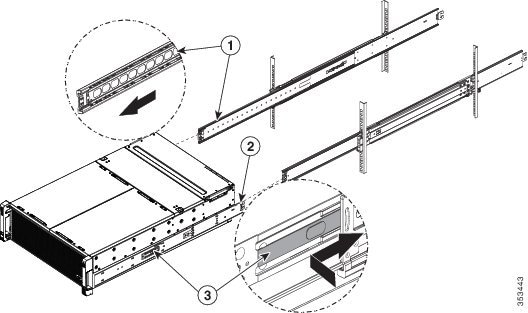
Step 4![]() Pull the intermediate slide rails on each assembly out toward the rack front until they hit the internal stops and lock in place (see Figure 2-4).
Pull the intermediate slide rails on each assembly out toward the rack front until they hit the internal stops and lock in place (see Figure 2-4).
Step 5![]() Insert the chassis with inner rails into the intermediate rails:
Insert the chassis with inner rails into the intermediate rails:
Note![]() The rack rail channels are fragile to side loads. Install the chassis gently to avoid damaging the rails.
The rack rail channels are fragile to side loads. Install the chassis gently to avoid damaging the rails.
a.![]() Align the rear ends of the inner rails that are attached to the chassis sides with the front ends of the empty intermediate rails on the rack.
Align the rear ends of the inner rails that are attached to the chassis sides with the front ends of the empty intermediate rails on the rack.
b.![]() Very slowly push the chassis toward the rack. Ensure that the rail ends mesh to each other and are fully engaged at the top and bottom of the rail channels.
Very slowly push the chassis toward the rack. Ensure that the rail ends mesh to each other and are fully engaged at the top and bottom of the rail channels.
c.![]() Slowly push the chassis into the intermediate rails until it stops at the internal stops.
Slowly push the chassis into the intermediate rails until it stops at the internal stops.
d.![]() Depress the release clip on each inner rail inward, and then continue pushing the chassis into the rack until its front handle slam-latches engage with the rack posts (see Figure 2-4).
Depress the release clip on each inner rail inward, and then continue pushing the chassis into the rack until its front handle slam-latches engage with the rack posts (see Figure 2-4).
Figure 2-4 Attaching Rail Assembly to the Rack Post
|
|
|
||
|
|
|
Step 6![]() (Recommended) Secure the chassis in the rack more permanently by using the two screws provided with the slide rails. For example, you can install these screws if you plan to move the rack with systems installed.
(Recommended) Secure the chassis in the rack more permanently by using the two screws provided with the slide rails. For example, you can install these screws if you plan to move the rack with systems installed.
With the chassis fully pushed into the slide rails, open a hinged slam-latch lever on the front of the system and insert the screw through the hole that is under the lever. The screw threads into the static part of the rail on the rack post and prevents the chassis from being pulled out. Repeat for the opposite slam latch.
Installing the Cable Management Arm (Optional)
Note![]() The internal drives and cooling fans in the system are hot-swappable and are accessed by opening the top covers. When you rack and cable the system, be sure to allow enough slack in the power cable and other cables so that the system can be pulled out on the slide rails far enough to allow clearance for opening the top covers.
The internal drives and cooling fans in the system are hot-swappable and are accessed by opening the top covers. When you rack and cable the system, be sure to allow enough slack in the power cable and other cables so that the system can be pulled out on the slide rails far enough to allow clearance for opening the top covers.
The CMA is reversible left to right. To reverse the CMA, see Reversing the Cable Management Arm (Optional) before installation.
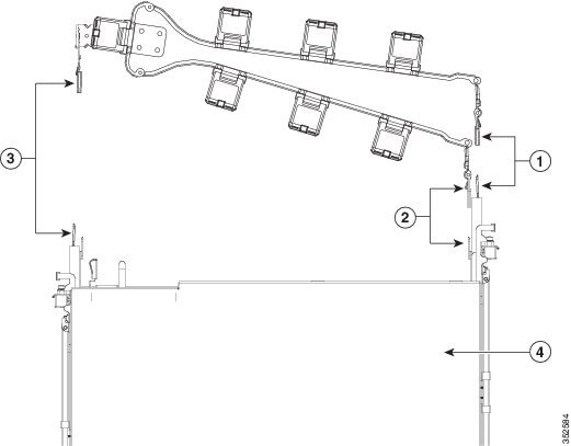
Step 1![]() With the system pushed fully into the rack, slide the CMA tab of the CMA arm that is farthest from the system onto the end of the stationary slide rail that is attached to the rack post (see Figure 2-5). Slide the tab over the end of the rail until it clicks and locks.
With the system pushed fully into the rack, slide the CMA tab of the CMA arm that is farthest from the system onto the end of the stationary slide rail that is attached to the rack post (see Figure 2-5). Slide the tab over the end of the rail until it clicks and locks.
Step 2![]() Slide the CMA tab that is closest to the system over the end of the inner rail that is attached to the system (see Figure 2-5). Slide the tab over the end of the rail until it clicks and locks.
Slide the CMA tab that is closest to the system over the end of the inner rail that is attached to the system (see Figure 2-5). Slide the tab over the end of the rail until it clicks and locks.
Step 3![]() Pull out the width-adjustment slider that is at the opposite end of the CMA assembly until it matches the width of your rack (see Figure 2-5).
Pull out the width-adjustment slider that is at the opposite end of the CMA assembly until it matches the width of your rack (see Figure 2-5).
Step 4![]() Slide the CMA tab that is at the end of the width-adjustment slider onto the end of the stationary slide rail that is attached to the rack post (see Figure 2-5). Slide the tab over the end of the rail until it clicks and locks.
Slide the CMA tab that is at the end of the width-adjustment slider onto the end of the stationary slide rail that is attached to the rack post (see Figure 2-5). Slide the tab over the end of the rail until it clicks and locks.
Step 5![]() Open the hinged flap at the top of each plastic cable guide and route your cables through the cable guides as desired.
Open the hinged flap at the top of each plastic cable guide and route your cables through the cable guides as desired.
Figure 2-5 Attaching the Cable Management Arm to the Rear of the Slide Rails
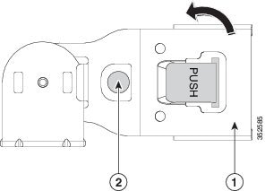
Reversing the Cable Management Arm (Optional)
Step 1![]() Rotate the entire CMA assembly 180 degrees. The plastic cable guides must remain pointing upward.
Rotate the entire CMA assembly 180 degrees. The plastic cable guides must remain pointing upward.
Step 2![]() Flip the tabs at the end of each CMA arm so that they point toward the rear of the system.
Flip the tabs at the end of each CMA arm so that they point toward the rear of the system.
Step 3![]() Pivot the tab that is at the end of the width-adjustment slider. Depress and hold the metal button on the outside of the tab and pivot the tab 180 degrees so that it points toward the rear of the system.
Pivot the tab that is at the end of the width-adjustment slider. Depress and hold the metal button on the outside of the tab and pivot the tab 180 degrees so that it points toward the rear of the system.
|
|
|
Initial System Setup
The following is a high-level summary of the setup steps and the sections in this doc for each step.
1.![]() Be aware of the default networking settings before you begin:
Be aware of the default networking settings before you begin:
2.![]() Be aware of the requirement to set as many as five IP addresses:
Be aware of the requirement to set as many as five IP addresses:
3.![]() If you plan to use a DHCP server, be aware of the requirements:
If you plan to use a DHCP server, be aware of the requirements:
4.![]() Connect cables and power on the system, then start the Cisco IMC Configuration Utility:
Connect cables and power on the system, then start the Cisco IMC Configuration Utility:
Connecting the System and Opening the Setup Utility
5.![]() Make networking settings using the Cisco IMC Configuration Utility:
Make networking settings using the Cisco IMC Configuration Utility:
Setting Up the System Using the Cisco IMC Configuration Utility
6.![]() Static IPs only—Set CMC and BMC IP addresses using the Cisco IMC management interface:
Static IPs only—Set CMC and BMC IP addresses using the Cisco IMC management interface:
Setting Static CMC and BMC Internal IP Addresses
Default Networking Settings
The system is shipped with these settings:
- The default NIC mode is Cisco Card. The QSFP ports on either SIOC are used to access the Cisco Integrated Management Controller (Cisco IMC) interface.
If you want to use the 10/100/1000 dedicated management port to access the Cisco IMC, you can connect to the system and change the NIC mode to Dedicated as described in Setting Up the System Using the Cisco IMC Configuration Utility.
System IP Addresses
A Cisco UCS S3260 system can have up to five IP addresses:
Note![]() All controllers present in the system must have IP addresses assigned in order to communicate with each other. All IP addresses can be assigned by your DHCP server, or you can assign static IP addresses.
All controllers present in the system must have IP addresses assigned in order to communicate with each other. All IP addresses can be assigned by your DHCP server, or you can assign static IP addresses.
- Management IP—This is the overall system virtual IP address. You log into this address when you access the system’s Cisco IMC interface via your LAN connection to the active chassis management controller in SIOC 1 or SIOC 2 (see Overview of Cisco UCS S3260 Architecture).
- SIOC 1 CMC IP—This is the internal address for the chassis management controller (CMC) in SIOC 1. This address can be assigned by your DHCP server, or you can set a static address by using the Cisco IMC interface.
- SIOC 2 CMC IP—This is the internal address for the CMC in SIOC 2 (if installed). This address can be assigned by your DHCP server, or you can set a static address by using the Cisco IMC interface.
- Server 1 BMC IP—This is the internal address for the board management controller (BMC) in server node 1. This address can be assigned by your DHCP server, or you can set a static address by using the Cisco IMC interface.
- Server 2 BMC IP—This is the internal address for the BMC in server node 2 (if installed). This address can be assigned by your DHCP server, or you can set a static address by using the Cisco IMC interface.
Note![]() The IP addresses for the management IP, the SIOC CMC IPs, and the server BMC IPs must all be configured on the same subnet.
The IP addresses for the management IP, the SIOC CMC IPs, and the server BMC IPs must all be configured on the same subnet.
DHCP Requirements
To configure the system remotely, you must have a DHCP server on the same network as the system. Your DHCP server must be preconfigured with the range of MAC addresses for the chassis management controller (CMC) in the system I/O controller (SIOC). Each SIOC has a range of six MAC addresses assigned. The MAC address printed on the label defines the beginning of the range of six contiguous MAC addresses.
The MAC address is printed on a label on the SIOC top cover.
Connecting the System and Opening the Setup Utility
This procedure instructs you how to assign the management IP address that you use to manage the whole system. It also walks through initial settings in the Cisco IMC Configuration Utility.
Note![]() If you use a 40G-to-10G splitter cable, you must configure the four 10G ports connected to the cable on the uplink switch side as part of a single static port-channel. It is possible to use less than four ports, if all used 10G ports are part of the same static port-channel. You must also set "spanning-tree port type edge trunk" on the port channel to eliminate STP transition time.
If you use a 40G-to-10G splitter cable, you must configure the four 10G ports connected to the cable on the uplink switch side as part of a single static port-channel. It is possible to use less than four ports, if all used 10G ports are part of the same static port-channel. You must also set "spanning-tree port type edge trunk" on the port channel to eliminate STP transition time.
Step 1![]() Attach a power cord to each power supply in your system, and then attach each power cord to a grounded AC power outlet. Wait for approximately five minutes to let the server nodes boot to standby power during the first bootup.
Attach a power cord to each power supply in your system, and then attach each power cord to a grounded AC power outlet. Wait for approximately five minutes to let the server nodes boot to standby power during the first bootup.
You can verify system power status by looking at the system Power Status LED on the front panel (see Figure 1-1). The system is in standby power mode when the LED is amber.
Step 2![]() Connect a KVM cable (Cisco PID N20-BKVM) to the KVM connector on either server node at the rear of the system.
Connect a KVM cable (Cisco PID N20-BKVM) to the KVM connector on either server node at the rear of the system.
Step 3![]() Connect a USB keyboard and a VGA monitor to the KVM cable.
Connect a USB keyboard and a VGA monitor to the KVM cable.
Step 4![]() Connect QSFP cables to the QSFP connectors on both SIOCs.
Connect QSFP cables to the QSFP connectors on both SIOCs.
Note![]() If you plan on changing the NIC mode to use the dedicated management port to manage the server, also attach an RJ-45 Ethernet cable to the management port on the SIOCs.
If you plan on changing the NIC mode to use the dedicated management port to manage the server, also attach an RJ-45 Ethernet cable to the management port on the SIOCs.
Step 5![]() Press and hold the front panel power button for four seconds to boot the system.
Press and hold the front panel power button for four seconds to boot the system.
Step 6![]() Open the Cisco IMC Configuration Utility:
Open the Cisco IMC Configuration Utility:
a.![]() Press and hold the front panel power button for four seconds to boot the system. Watch the screen for the prompt to press F8.
Press and hold the front panel power button for four seconds to boot the system. Watch the screen for the prompt to press F8.
b.![]() During bootup, press F8 when prompted to open the Cisco IMC Configuration Utility.
During bootup, press F8 when prompted to open the Cisco IMC Configuration Utility.
This utility has three windows that you can toggle between by pressing F1 or F2.
Note![]() The first time that you enter the Cisco IMC Configuration Utility, you are prompted to change the default password. The default password is password.
The first time that you enter the Cisco IMC Configuration Utility, you are prompted to change the default password. The default password is password.
The following are the requirements for a strong password:
- The password can have minimum 8 characters; maximum 14 characters.
- The password must not contain the user’s name.
- The password must contain characters from three of the following four categories:
–![]() English uppercase letters (A through Z).
English uppercase letters (A through Z).
–![]() English lowercase letters (a through z).
English lowercase letters (a through z).
–![]() Base 10 digits (0 through 9).
Base 10 digits (0 through 9).
–![]() Non-alphabetic characters !, @, #, $, %, ^, &, *, -, _, =, “
Non-alphabetic characters !, @, #, $, %, ^, &, *, -, _, =, “
Step 7![]() Continue with Setting Up the System Using the Cisco IMC Configuration Utility.
Continue with Setting Up the System Using the Cisco IMC Configuration Utility.
Setting Up the System Using the Cisco IMC Configuration Utility
The following procedure is performed after you connect to the system and open the Cisco IMC Configuration Utility by pressing F8 during boot.
Step 1![]() Set NIC mode and NIC redundancy:
Set NIC mode and NIC redundancy:
Note![]() The NIC modes and NIC redundancy refer to the ports on the SIOCs. They do not refer to the 1-Gb LOM port on an S3260 M5 server node.
The NIC modes and NIC redundancy refer to the ports on the SIOCs. They do not refer to the 1-Gb LOM port on an S3260 M5 server node.
a.![]() NIC Mode —Set the NIC mode to select which ports to use for accessing the Cisco IMC management interface:
NIC Mode —Set the NIC mode to select which ports to use for accessing the Cisco IMC management interface:
- Cisco Card (default)—The QSFP ports on the active SIOC are used to access Cisco IMC. You must select a NIC redundancy setting.
- Dedicated—The dedicated RJ-45 management port of the active SIOC is used to access the Cisco IMC. The only NIC redundancy setting for this NIC mode is None.
- Active SIOC Slot—You cannot change this value. This field shows which SIOC/chassis management controller is active. The two SIOCs operate in an active-standby failover relationship (see Management Architecture).
b.![]() NIC redundancy —There are three possible NIC redundancy settings:
NIC redundancy —There are three possible NIC redundancy settings:
- Active-active (default)—All QSFP ports are utilized simultaneously. This setting can be used only with the Cisco Card NIC mode.
- Active-standby—If an active QSFP port fails, traffic fails over to a standby port. This setting can be used only with the Cisco Card NIC mode.
- None—The ports operate independently and do not fail over if there is a problem. This setting can be used only with the Dedicated NIC mode.
Step 2![]() Select whether to use IPv4 (default) or IPv6.
Select whether to use IPv4 (default) or IPv6.
If you select to use IPv6, the IPv4 details are hidden because of space constraints on the screen.
Step 3![]() Choose whether to keep DHCP enabled (default), or to disable and then enter static network settings.
Choose whether to keep DHCP enabled (default), or to disable and then enter static network settings.
Note![]() If you use a DHCP server and you already have QSFP cables attached to the SIOCs, the management IP address and network settings are already filled in. If you disable DHCP, you must set your own static management IP address and network settings.
If you use a DHCP server and you already have QSFP cables attached to the SIOCs, the management IP address and network settings are already filled in. If you disable DHCP, you must set your own static management IP address and network settings.
The static IPv4 and IPv6 settings include:
- The Management IP address (the address that you use to access the Cisco IMC interface).
- The prefix/subnet.
For IPv6, valid values are 1–127.
Note![]() The IP addresses for the management IP, the SIOC CMC IPs, and the server BMC IPs must all be configured on the same subnet.
The IP addresses for the management IP, the SIOC CMC IPs, and the server BMC IPs must all be configured on the same subnet.
For IPv6, if you do not know the gateway, you can set it as none by typing :: (two colons).
For IPv6, you can set this as none by typing :: (two colons).
Step 4![]() Optional: Use this utility to make VLAN settings.
Optional: Use this utility to make VLAN settings.
Note![]() Save your changes by pressing F10 before switching windows.
Save your changes by pressing F10 before switching windows.
Step 5![]() Press F1 to go to the second settings window, then continue with the next step.
Press F1 to go to the second settings window, then continue with the next step.
From the second window, you can press F2 to switch back to the first window.
Step 6![]() Optional: Set a host name.
Optional: Set a host name.
Step 7![]() Optional: Enable dynamic DNS and set a dynamic DNS (DDNS) domain.
Optional: Enable dynamic DNS and set a dynamic DNS (DDNS) domain.
Step 8![]() Optional: The Factory Default check box has two options:
Optional: The Factory Default check box has two options:
- Server Controller Configuration: the selected server node is set back to its factory default state and the selected server/host reboots.
- Chassis Controller Configuration: Both CMCs in the SIOCs are set to the factory default state.
Step 9![]() Optional: Set port properties for the 10/100/1000 dedicated management port on the SIOCs if you do not want the port to use the auto-negotiation feature.
Optional: Set port properties for the 10/100/1000 dedicated management port on the SIOCs if you do not want the port to use the auto-negotiation feature.
Step 10![]() Optional: Reset port profiles and the port name.
Optional: Reset port profiles and the port name.
Note![]() Save your changes by pressing F10 before switching windows.
Save your changes by pressing F10 before switching windows.
Step 11![]() Press F1 to go to the third settings window, then continue with the next step.
Press F1 to go to the third settings window, then continue with the next step.
From the third window, you can press F2 to switch back to the first window.
Step 12![]() Optional: Set the port speed for the SIOC QSFP ports to either 40 Gbps or 4x10 Gbps.
Optional: Set the port speed for the SIOC QSFP ports to either 40 Gbps or 4x10 Gbps.
“Adapter-1” refers to SIOC 1 and “Adapter-2” refers to SIOC 2, if present.
Note![]() If your system is running Cisco IMC 2.0(9) or later, the default setting is Auto, which automatically adjusts to your network installation.
If your system is running Cisco IMC 2.0(9) or later, the default setting is Auto, which automatically adjusts to your network installation.
Note![]() If you use a 40G-to-10G splitter cable, you must configure the four 10G ports connected to the cable on the uplink switch side as part of a single static port-channel. It is possible to use less than four ports, if all used 10G ports are part of the same static port-channel. You must also set "spanning-tree port type edge trunk" on the port channel to eliminate STP transition time.
If you use a 40G-to-10G splitter cable, you must configure the four 10G ports connected to the cable on the uplink switch side as part of a single static port-channel. It is possible to use less than four ports, if all used 10G ports are part of the same static port-channel. You must also set "spanning-tree port type edge trunk" on the port channel to eliminate STP transition time.
Step 13![]() Press F5 to refresh the settings you made. You might have to wait about 45 seconds until the new settings appear and the message
Press F5 to refresh the settings you made. You might have to wait about 45 seconds until the new settings appear and the message Network settings configured is displayed before you reboot the server node in the next step.
Step 14![]() Press F10 to save your settings and reboot the server node.
Press F10 to save your settings and reboot the server node.
Note![]() If you chose to leave DHCP enabled, the dynamically assigned IP and MAC addresses are displayed on the console screen during bootup.
If you chose to leave DHCP enabled, the dynamically assigned IP and MAC addresses are displayed on the console screen during bootup.
Step 15![]() Remove the KVM cable from the server node.
Remove the KVM cable from the server node.
Note![]() Each CMC in the SIOCs and each BMC in the server nodes must have an internal IP address assigned in order for the system to operate (see System IP Addresses). If DHCP is enabled, your DHCP server assigns these addresses and no further steps are required.
Each CMC in the SIOCs and each BMC in the server nodes must have an internal IP address assigned in order for the system to operate (see System IP Addresses). If DHCP is enabled, your DHCP server assigns these addresses and no further steps are required.
Step 16![]() This step only for setting static IPs (DHCP disabled) —Set the CMC and BMC internal IP addresses by using the Cisco IMC interface, as described in Setting Static CMC and BMC Internal IP Addresses.
This step only for setting static IPs (DHCP disabled) —Set the CMC and BMC internal IP addresses by using the Cisco IMC interface, as described in Setting Static CMC and BMC Internal IP Addresses.
Setting Static CMC and BMC Internal IP Addresses
Note![]() If you left DHCP enabled, your DHCP server sets the CMC and BMC IP addresses and so these steps are not required. Perform the following procedure only if you are setting static IP addresses manually.
If you left DHCP enabled, your DHCP server sets the CMC and BMC IP addresses and so these steps are not required. Perform the following procedure only if you are setting static IP addresses manually.
Step 1![]() Use a browser and the system management IP address to connect to the Cisco IMC management interface.
Use a browser and the system management IP address to connect to the Cisco IMC management interface.
Step 2![]() Log in at the login page. The default user name for the system is admin. The default password is password.
Log in at the login page. The default user name for the system is admin. The default password is password.
The Chassis/Summary page opens. The Management IP Address is displayed. The IP address for each CMC is displayed at this point only if a DHCP server assigned them.
Step 3![]() Click the menu button at the upper-left corner
Click the menu button at the upper-left corner  and select Admin > Networking.
The Networking/Network Settings page opens.
Step 4![]() Scroll down to the Individual Settings area.
Scroll down to the Individual Settings area.
Step 5![]() Fill in your static IP addresses for CMC1, CMC2, BMC1, and BMC2.
Fill in your static IP addresses for CMC1, CMC2, BMC1, and BMC2.
Note![]() All available component IP addresses must be set together to complete the configuration. Partial settings result in an error and the partial settings are not saved.
All available component IP addresses must be set together to complete the configuration. Partial settings result in an error and the partial settings are not saved.
Note![]() The IP addresses for the management IP, the SIOC CMC IPs, and the server BMC IPs must all be configured on the same subnet.
The IP addresses for the management IP, the SIOC CMC IPs, and the server BMC IPs must all be configured on the same subnet.
This task can be completed using the management GUI or CLI interfaces. For more information see Cisco UCS C-Series Integrated Management Controller GUI Configuration Guide for S3260 Servers or the Cisco UCS C-Series Integrated Management Controller CLI Configuration Guide for S3260 Servers here: Configuration Guides.
NIC Modes and NIC Redundancy Settings
Note![]() The NIC modes and NIC redundancy refer to the ports on the SIOCs. They do not refer to the 1-Gb LOM port on an S3260 M5 server node.
The NIC modes and NIC redundancy refer to the ports on the SIOCs. They do not refer to the 1-Gb LOM port on an S3260 M5 server node.
NIC Modes
NIC Redundancy
You can choose from the following NIC redundancy settings:
- Active-active (default)—All QSFP ports are utilized simultaneously. This setting can be used only with the Cisco Card NIC mode.
- Active-standby—If an active QSFP port fails, traffic fails over to a standby port. This setting can be used only with the Cisco Card NIC mode.
- None—The ports operate independently and do not fail over if there is a problem. This setting can be used only with the Dedicated NIC mode.
System BIOS and Cisco IMC Firmware
This section includes information about the system BIOS and it includes the following topics:
Updating the BIOS and Cisco IMC Firmware
The system uses firmware that is obtained from and certified by Cisco. Cisco provides release notes with each firmware image.
The recommended method is to use the Cisco Host Upgrade Utility to simultaneously upgrade the Cisco IMC, BIOS, and other component firmware to compatible levels.
See the Cisco Host Upgrade Utility Quick Reference Guide for your firmware level.
Accessing the System BIOS
Note![]() Details about the BIOS settings are displayed in the BIOS windows.
Details about the BIOS settings are displayed in the BIOS windows.
Step 1![]() Enter the BIOS setup utility by pressing the F2 key when prompted during bootup.
Enter the BIOS setup utility by pressing the F2 key when prompted during bootup.
Note![]() The version and build of the current BIOS are displayed on the Main page of the utility.
The version and build of the current BIOS are displayed on the Main page of the utility.
Step 2![]() Use the arrow keys to select the BIOS menu page.
Use the arrow keys to select the BIOS menu page.
Step 3![]() Use the arrow keys to highlight the field to be modified.
Use the arrow keys to highlight the field to be modified.
Step 4![]() Press Enter to select the field that you want to change, and then modify the value in the field.
Press Enter to select the field that you want to change, and then modify the value in the field.
Step 5![]() Press the right arrow key until the Exit menu screen is displayed.
Press the right arrow key until the Exit menu screen is displayed.
Step 6![]() Follow the instructions on the Exit menu screen to save your changes and exit the setup utility (or press F10). You can exit without saving changes by pressing Esc.
Follow the instructions on the Exit menu screen to save your changes and exit the setup utility (or press F10). You can exit without saving changes by pressing Esc.
 Feedback