|
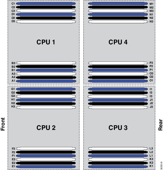
1
|
A1
|
E1
|
I1
|
M1
|
Blue
|
|
2
|
A1, B1
|
E1, F1
|
I1, J1
|
M1, N1
|
Blue
|
|
3
|
A1, B1, C1
|
E1, F1, G1
|
I1, J1, K1
|
M1, N1, O1
|
Blue
|
|
4
|
A1, B1, C1, D1
|
E1, F1, G1, H1
|
I1, J1, K1, L1
|
M1, N1, O1, P1
|
Blue
|
|
5
|
Not recommended for
performance reasons.
|
|
6
|
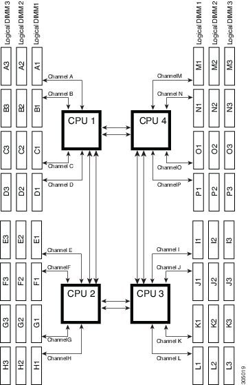
A1, B1, C1,
A2, B2, C2
|
E1, F1, G1,
E2, F2, G2
|
I1, J1, K1,
I2, J2, K2
|
M1, N1, O1, M2, N2, O2
|
Blue,
Black
|
|
7
|
Not recommended for
performance reasons.
|
|
8
|
A1, B1, C1, D1,
A2, B2, C2, D2
|
E1, F1, G1, H1, E2, F2, G2,
H2
|
I1, J1, K1, L1, I2, J2, K2,
L2
|
M1, N1, O1, P1, M2, N2, O2,
P2
|
Blue,
Black
|
|
9
|
A1, B1, C1,
A2, B2, C2,
A3, B3, C3
|
E1, F1, G1,
E2, F2,
G2,
E3, F3, G3
|
I1, J1, K1,
I2, J2, K2,
I3, J3, K3
|
M1, N1, O1,
M2, N2, O2,
M3, N3, O3
|
Blue,
Black,
White
|
|
10
|
Not recommended for
performance reasons.
|
|
11
|
Not recommended for
performance reasons.
|
|
12
|
A1, B1, C1, D1,
A2, B2, C2, D2,
A3, B3, C3, D3
|
E1, F1, G1, H1, E2, F2, G2,
H2, E3, F3, G3, H3
|
I1, J1, K1, L1, I2, J2, K2,
L2, I3, J3, K3, L3
|
M1, N1, O1, P1, M2, N2, O2,
P2, M3, N3, O3, P3
|
Blue,
Black,
White
|


 Feedback