Overview

This chapter contains the following sections:

Cisco UCS B420 M4 High Performance Blade Server

This document describes how to install and service the Cisco UCS B420 M4 high performance blade server, a full-width, high-density blade server that supports the following features:

  • Up to four Intel Xeon E5-4600 v4 or v3 CPUs, interconnected with Intel QuickPath Interconnect (QPI) links. Two- and four-CPU configurations are supported.

  • 48 DDR4 DIMMs, either RDIMMs, LRDIMMs, or TSV-RDIMMs.

  • 3 mezzanine adapter slots.

  • Up to 4 SAS or SATA hard disk drives (HDDs) or solid state drives (SSDs).

Up to four Cisco UCS B420 M4 blade servers can reside in a Cisco UCS 5108 Blade Server chassis.
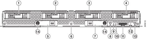
Figure 1. Cisco UCS B420 M4 Blade Server Front Panel

1

Hard drive bay 1

8

Power button and LED

2

Hard drive bay 2

9

Network link status LED

3

Hard drive bay 3

10

Blade health LED

4

Hard drive bay 4

11

Local console connector

5

Left ejector handle

12

Reset button access

6

Asset pull tab

13

Locator button LED

7

Right ejector handle

14

Ejector captive screw

LEDs

Server LEDs indicate whether the blade server is in active or standby mode, the status of the network link, the overall health of the blade server, and whether the server is set to give a flashing blue locator light from the locator button.

The removable drives also have LEDs indicating hard disk access activity and disk health.

Table 1. Blade Server LEDs

LED

Color

Description

Power

Off

Power off.

Green

Main power state. Power is supplied to all server components and the server is operating normally.

Amber

Standby power state. Power is supplied only to the service processor of the server so that the server can still be managed.

Note


Of you press and release the front-panel power button, the server performs an orderly shutdown of the 12 V main power and goes to standby power state. You cannot shut down standby power from the front-panel power button. See the Cisco UCS Manager Configuration Guide for information about completely power off the server from the software interface.

Link

Off

None of the network links are up.

Green

At least one network link is up.

Health

Off

Power off.

Green

Normal operation.

Amber

Minor error.

Blinking Amber

Critical error.

Blue locator button and LED

Off

Blinking is not enabled.

Blinking blue 1 Hz

Blinking to locate a selected blade—If the LED is not blinking, the blade is not selected. You can control the blinking in UCS Manager or by using the blue locator button/LED.

Activity

(Disk Drive)

Off

Inactive.

Green

Outstanding I/O to disk drive.

Flashing Green 1 Hz

Rebuild in progress. Health LED will flash in unison.

Flashing Green 4 Hz

Identify drive as active.

Health

(Disk Drive)

Off

Either no fault is detected or the drive is not installed.

Amber

Fault detected.

Flashing Amber 4 Hz

Rebuild drive active. If the Activity LED is also flashing green, a drive rebuild is in progress.

Buttons

The Reset button is recessed in the front panel of the server. You can press the button with the tip of a paper clip or a similar item. Hold the button down for five seconds, and then release it to restart the server if other methods of restarting do not work.

The locator function for an individual server may get turned on or off by pressing the locator button/LED.

The power button allows you to manually take a server temporarily out of service but leave it in a state where it can be restarted quickly. If the desired power state for a service profile associated with a blade server is set to "off," using the power button or Cisco UCS Manager to reset the server will cause the desired power state of the server to become out-of-sync with the actual power state and the server may unexpectedly shut down at a later time. To safely reboot a server from a power-down state, use the Boot Server action in Cisco UCS Manager.

Local Console Connection

The local console connector allows a direct connection to a blade server to allow operating system installation and other management tasks to be done directly rather than remotely. The port uses the KVM dongle cable that provides a connection into a Cisco UCS blade server; it has a DB9 serial connector, a VGA connector for a monitor, and dual USB ports for a keyboard and mouse. With this cable, you can create a direct connection to the operating system and the BIOS running on a blade server. A KVM cable ships standard with each blade chassis accessory kit.

Figure 2. KVM Cable for Blade Servers

1

Connector to blade server local console connection

2

DB9 serial connector

3

VGA connector for a monitor

4

2-port USB connector for a mouse and keyboard

Secure Digital Cards

Secure Digital (SD) card slots are provided and one or two SD cards can be populated. If two SD cards are populated, they can be used in a mirrored mode.


Note


Do not mix different capacity cards in the same server.


Figure 3. SD Card Slots

Modular Storage Subsystem

The Cisco UCS B420 M4 blade server has two optional FlexStorage modular storage subsystems that can be configured with SAS or SATA hard disk drives (HDDs) or solid state disks (SSDs). The product IDs for the modular storage subsystems are as follows:
  • UCSB-MRAID12G, Cisco FlexStorage 12G SAS RAID controller with drive bays

  • UCSB-MRAID12G-HE, Cisco FlexStorage 12G SAS RAID controller with 2 GB flash-back write cache and drive bays

  • UCSB-LSTOR-PT, passthrough module with drive bays

  • UCSB-LSTOR-BK, Cisco FlexStorage blanking panels without controller or drive bays

Because the blade server can be used without disk drives, it does not come with any modular storage subsystems installed. Blanking panels should be used on a diskless UCS B420 M4 blade server to ensure proper airflow. Order the same number of blanking panels as there are empty drive bays.

There are two RAID controller options for the modular storage subsystems. One supports RAID 0, 1, 10 and the other supports RAID 0, 1, 10, 5, 6, with optional 2 GB flash-backed write cache, when four drives are present.

Drive Bay and RAID Controller Configurations

The Cisco UCS B420 M4 blade server supports the following configurations of drive bays and RAID controllers.

Configuration

Description

Four drive bays with RAID 0, 1, 10

This configuration includes:

  • One UCSB-MRAID12G that provides two drives bays on the left side of the blade server (when facing the front). The RAID controller is integrated in the drive bays and provides RAID 0, 1, 10.

  • One UCSB-LSTOR-PT that provides two drive bays installed on the right (when facing the front) and includes a passthrough connector that allows the drives to be managed from the RAID controller in UCSB-MRAID12G.

Four drive bays with RAID 0, 1, 10, 5, 6

This configuration includes:

  • One UCSB-MRAID12G-HE that provides two drives bays on the left side of the blade server (when facing the front). The RAID controller has a 2 GB flash-backed write cache (FBWC) for high performance, is integrated in the drive bays and provides RAID 0, 1, 10, 5, 6.

  • One UCSB-LSTOR-PT that provides two drive bays installed on the right (when facing the front) and includes a passthrough connector that allows the drives to be managed from the RAID controller in UCSB-MRAID12G-HE.

Two drive bays with RAID 0, 1, 10

This configuration includes:

  • One UCSB-MRAID12G that provides two drives bays on the left side of the blade server (when facing the front). The RAID controller is integrated in the drive bays and provides RAID 0, 1, 10. The right-hand bays have blanking panels installed to maintain proper airflow.

Two drive bays with RAID 0, 1, 10

This configuration includes:

  • One UCSB-MRAID12G-HE that provides two drives bays on the left side of the blade server (when facing the front). The RAID controller has a 2 GB flash-backed write cache (FBWC) for high performance, is integrated in the drive bays and provides RAID 0, 1, 10. The right-hand bays have blanking panels installed to maintain proper airflow.

No drive bays

This configuration does not include drive bays or RAID controllers. The diskless server must be booted from a network. Blanking panels must be installed in the empty drive bays.