Overview

Overview

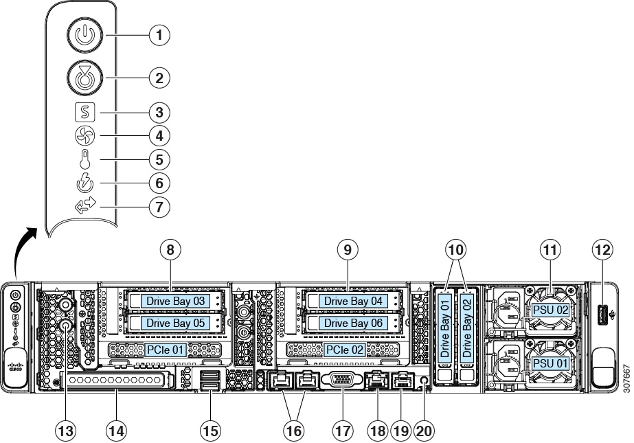
Cisco UCS C240 SD M5 (UCSC-C240-M5SD) server is orderable in one version with two possible PCIe riser combinations.

  • PCIe Riser 1 (UCSC-RIS-1-240M5) and PCIe Riser 2B (UCSC-RIS-2B-240M5)—This combination supports:

    • Two vertical drive bays with up to two 2.5-inch SAS/SATA drives; or up to two 2.5-inch NVMe SSDs.

    • Six PCIe slots

  • PCIe Riser 1C (UCSC-RS1C-240M5SD) and PCIe Riser 2E (UCSC-RS2E-240M5SD)—This combination supports:

    • Four drive bays in the PCIe risers support 2.5-inch SAS/SATA drives; or up to two 2.5-inch NVMe SSDs.

    • Two vertical drive bays support up to two 2.5-inch SAS/SATA drives; or up to two 2.5-inch NVMe SSDs.

    • Two PCIe slots


Note


Any other combination is not supported.


External Features

This topic shows the external features of the server versions.

For definitions of LED states, see Front-Panel LEDs.

Cisco UCS C240 SD M5 Server Front Panel Features

The following figure shows the front panel features of Cisco UCS C240 SD M5 server.

For definitions of LED states, see Front-Panel LEDs.

Figure 1. Cisco UCS C240 SD M5 Server Front Panel

1

Power button/power status LED

11

Power supplies (two, redundant as 1+1)

See Power Specifications for specifications and supported options.

2

Unit identification button/LED

12

USB 2.0 port

3

System health LED

13

Threaded holes for dual-hole grounding lug.

4

Fan status LED

14

Modular LAN-on-motherboard (mLOM) card slot (x16)

5

Temperature status LED

15

USB 3.0 ports (two)

6

Power supply status LED

16

Dual 1-Gb/10-Gb Ethernet ports (LAN1 and LAN2)

The dual LAN ports can support 1 Gbps and 10 Gbps, depending on the link partner capability.

7

Network link activity LED

17

VGA video port (DB-15 connector)

8

PCIe riser 1 with the following options (Drive bays 03 and 05, and PCIe 01):

  • 1—Slots 1 (x8), 2 (x16), 3 (x8); slot 3 requires CPU2.

  • 1C—Drive bay 03 (x4), Drive bay 05 (x4), PCIe 1 (x16); all slots supported by CPU1

See PCIe Slot Specifications for slot specifications.

18

1-Gb Ethernet dedicated management port

9

PCIe riser 2 with the following options (Drive bays 04 and 06, and PCIe 02):

  • 2B—Slots 4 (x8), 5 (x16), 6 (x8); slot 3 requires CPU2.

  • 2E—Drive bay 04 (x4), Drive bay 06 (x4), PCIe 4 (x16); all slots supported by CPU2

19

Serial port (RJ-45 connector)

10

Two 2.5-inch drive bays (Drive bays 01 and 02:

  • Supports only SAS/SATA HDD/SSD with SAS-backplane

  • Supports only NVME SSDs with NVMe-backplane

20

Front panel identification button/LED

Cisco UCS C240 SD M5 Server Rear Panel Features

The following figure shows the rear panel features of Cisco UCS C240 SD M5 server.

Figure 2. Cisco UCS C240 SD M5 Server Rear Panel

Serviceable Component Locations

This topic shows the locations of the field-replaceable components and service-related items. The view in the following figure shows the server with the top cover removed.

Figure 3. Cisco UCS C240 SD M5 Server, Serviceable Component Locations

1

Cooling fan modules (six, hot-swappable)

11

Two 2.5-inch drive bays (Drive bays 01 and 02:

  • Supports only SAS/SATA HDD/SSD with SAS-backplane

  • Supports only NVME SSDs with NVMe-backplane

2

DIMM sockets on motherboard (up to 12 per CPU)

Not visible under air baffle in this view.

See DIMM Population Rules and Memory Performance Guidelines for DIMM slot numbering.

12

PCIe riser 2 with the following options (Drive bays 04 and 06, and PCIe 02):

  • 2B—Slots 4 (x8), 5 (x16), 6 (x8); slot 3 requires CPU2.

  • 2E—Drive bay 04 (x4), Drive bay 06 (x4), PCIe 4 (x16); all slots supported by CPU2

3

CPUs and heatsinks (up to two)

Not visible under air baffle in this view.

13

Micro-SD socket on PCIe riser 01

4

SuperCap power module mounting clip on air baffle (if applicable)

14

PCIe riser 1 with the following options (Drive bays 03 and 05, and PCIe 01):

  • 1—Slots 1 (x8), 2 (x16), 3 (x8); slot 3 requires CPU2.

  • 1C—Drive bay 03 (x4), Drive bay 05 (x4), PCIe 1 (x16); all slots supported by CPU1

See PCIe Slot Specifications for slot specifications.

5

Internal, vertical USB 3.0 port on motherboard

15

Storage controller dedicated slot

6

Mini-storage module socket. Options:

  • SD card module with two SD card slots

  • M.2 module with slots for two SATA M.2 drives

16

mLOM card socket on board

7

Chassis intrusion switch (optional)

17

RTC battery

8

PCIe cable connectors for NVMe SSDs.

18

Securing clips for GPU cards on air baffle

9

Vertical drive backplane assembly

10

Power supplies (hot-swappable when redundant as 1+1)

The Technical Specifications Sheets for all versions of this server, which include supported component part numbers, are at Cisco UCS Servers Technical Specifications Sheets (scroll down to Technical Specifications).

Summary of Server Features

The following table lists a summary of server features.

Feature

Description

Chassis

Two rack-unit (2RU) chassis

Central Processor

Up to two CPUs from the Intel Xeon Processor Scalable Family. This includes CPUs from the following series:

  • Intel Xeon Bronze 3XXX Processors

  • Intel Xeon Silver 4XXX Processors

  • Intel Xeon Gold 5XXX Processors

  • Intel Xeon Gold 6XXX Processors

  • Intel Xeon Platinum 8XXX Processors

Memory

24 DDR4 DIMM sockets on the motherboard (12 each CPU)

Multi-bit error protection

Multi-bit error protection is supported

Baseboard management

BMC, running Cisco Integrated Management Controller (Cisco IMC) firmware.

Depending on your Cisco IMC settings, Cisco IMC can be accessed through the 1-Gb dedicated management port, the 1-Gb/10-Gb Ethernet LAN ports, or a Cisco virtual interface card.

Network and management I/O

Front panel:

  • One 1-Gb Ethernet dedicated management port (RJ-45 connector)

  • Two 1-Gb/10-Gb BASE-T Ethernet LAN ports (RJ-45 connectors)

    The dual LAN ports can support 1 Gbps and 10 Gbps, depending on the link partner capability.

  • One RS-232 serial port (RJ-45 connector)

  • One VGA video connector port (DB-15 connector)

  • Two USB 3.0 ports

  • One USC 2.0 port

Modular LOM

One dedicated socket (x16 PCIe lane) that can be used to add an mLOM card for additional front-panel connectivity.

Power

Two power supplies, redundant as 1+1:

  • AC power supplies 1050 W AC each

  • DC power supplies 1050 W DC each

Do not mix power supply types or wattages in the server.

ACPI

The advanced configuration and power interface (ACPI) 4.0 standard is supported.

Cooling

Six hot-swappable fan modules for front-to-rear cooling.

PCIe I/O

Two horizontal PCIe expansion slots on two PCIe riser assemblies.

See PCIe Slot Specifications for specifications of the slots.

InfiniBand

The PCIe bus slots in this server support the InfiniBand architecture.

Storage, front-panel

Four 2.5-inch drive bays on risers 1 and 2; Two 2.5-inch vertical drive bays.

  • Supports only SAS/SATA HDD/SSD with SAS-backplane

  • Supports only NVME SSDs with NVMe-backplane

SAS/SATA drives are hot-swappable. NVMe SSDs are hot-pluggable, meaning that they must be shut down in the operating system before hot-removal.

Storage, internal

The server has these internal storage options:

  • One USB 3.0 port on the motherboard.

  • One micro-SD card socket on PCIe riser 1.

  • Mini-storage module socket, optionally with either:

    • SD card carrier. Supports up to two SD cards.

    • M.2 SSD carrier. Supports two SATA M.2 SSDs.

    • Cisco Boot-Optimized M.2 RAID Controller (module with two slots for SATA M.2 drives, plus an integrated SATA RAID controller that can control the two SATA M.2 drives in a RAID 1 array)

Storage management

Dedicated internal slot for Cisco 12G SAS HBA only

For a detailed list of storage controller options, see Supported Storage Controllers and Cables.

RAID backup (if available)

The server has a mounting bracket on the removable air baffle for one supercap unit that is used with the Cisco modular RAID controller card.

Integrated video

Integrated VGA video.