Overview

This chapter contains the following topics:

Overview

The Cisco UCS C220 M8 server is a one-rack unit server that can be used standalone, or as part of the Cisco Unified Computing System, which unifies computing, networking, management, virtualization, and storage access into a single integrated architecture. Cisco UCS also enables end-to-end server visibility, management, and control in both bare metal and virtualized environments.

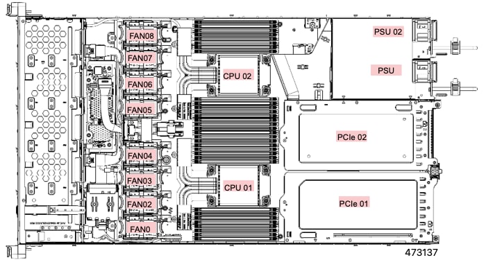
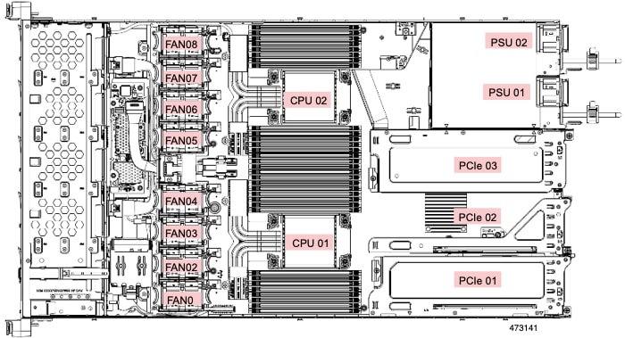
Each Cisco UCS C220 M8 has two CPU sockets that can support the Intel® Xeon® 6 Scalable Processors, in either one or two CPU configurations. These processors feature 86 cores per CPU, 350W TDP per socket, 3xUPI 2.0 at up to 24 GT/s, 8 distinct channels of DDR5 DIMMs, and support a maximum of 88 PCIe version 5.0 lanes.

Additionally, the server supports the following features with one CPU or two identical CPUs:

  • 32 DDR5 DIMMs (RDIMM) are supported on a dual-CPU server, and 16 DDR5 DIMMS (RDIMM) in a single-CPU server:

    • Up to 6400 MT/s for 1 DPC

    • Up to 5200 MT/s for 2DPC

    • Up to 8000 MT/S MR DIMMs

    • 16 DIMMs are supported per CPU for a total system memory of 8 TB (up to 256 GB DDR5 DIMMs).

  • DDR5 DIMM capacities vary based on the CPU type for the compute node. For more information, see DIMM Population Rules and Memory Performance Guidelines.

  • Intel Xeon 6 Scalable Processors support 16, 32, 48, 64, 96, 128, and 256 GB DDR5 DIMMs per CPU socket.

Additionally, the server supports the following features with one CPU or two identical CPUs:

  • The server has different supported configurations, which differ based on the number and type of storage drives installed.

    • The servers can support small form factor (SFF) and EDSFF (E3.S) drives, which are accessible through the server's front loading drive bays.

    • Support for M.2 SSDs:

      • The server supports up to 2x M.2 SATA drives which can be internal or rear accessible. The rear M.2s can be installed in the mLOM slot.

      • For boot RAID M.2 support: One M.2 Boot-Optimized RAID controller.

    • Optionally, GPUs can be installed in the rear PCIe risers:

      • Up to 3 single-wide GPUs.

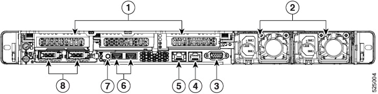
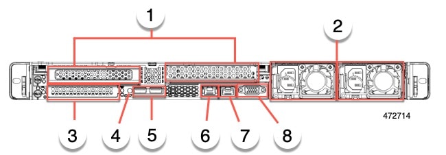
    • Internal slot for a 24 G Tri-Mode RAID controller with SuperCap for write-cache backup, or for a Tri-mode HBA.

    • One mLOM/VIC card provides 10/25/40/50/100/200 Gbps.

    • Two power supplies (PSUs) that support N+1 power configuration and cold redundancy.

    • Six modular, hot swappable fans.

  • Rear PCI risers are supported as one to three half-height half-length (HHHL) PCIe risers, or one to two full-height ¾ length PCIe risers.

  • Two KVM ports, one on the front of the server and on the rear

  • Modular Trusted Platform Module (TPM 2.0)

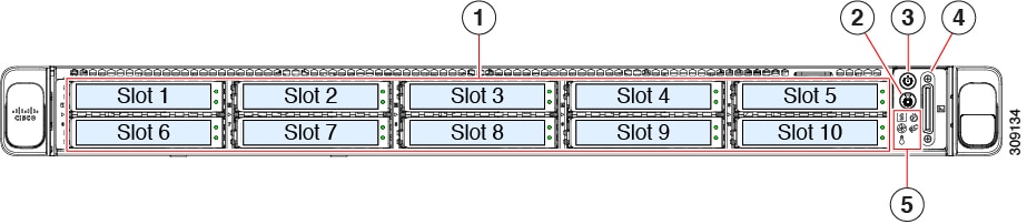
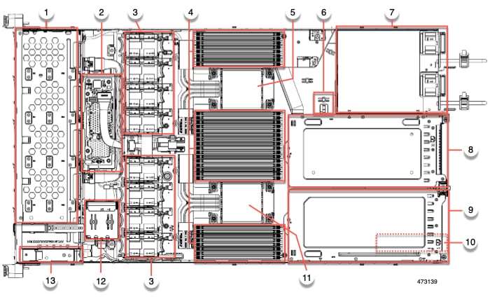
Server Configurations, UCSC-C220-M8S

The Cisco UCS C220 M8S server offers a hybrid backplane that supports the following:

  • Front-loading drive bays 1 through 10 support 2.5-inch SAS/SATA/U.3 NVMe drives.

  • U.3 NVMe drives are supported in all 10 slots when used in conjunction with the tri-mode storage controller.

  • Slots 1 through 4 and 6 through 9 can support direct attach NVMe SSDs (either U.2 or U.3) .

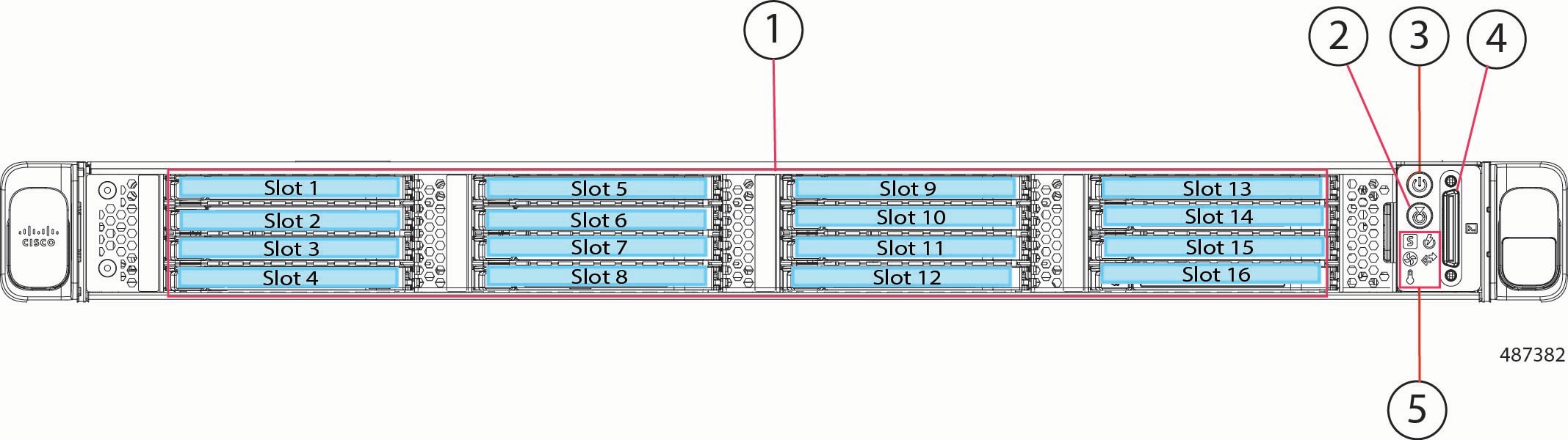
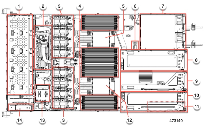
Server Configurations, UCSC-C220-M8E3S

The UCSC-C220-M8E3S server can be ordered as an E3.S NVMe-only server. This server has an NVMe backplane that supports the following:

  • Front-loading drive bays 1 through 16 support EDSFF E3.S IT NVMe drives


Note


E3.S NVMe drives are directly attached to the CPU and are not RAID controlled.


External Features

This topic shows the external features of the server versions.

Cisco UCS C220 M8 Server Front Panel Features, UCSC-C220-M8S

The following figure shows the front panel features of the small form-factor drive version of the server.

For definitions of LED states, see Removing the Server Top Cover.

Figure 1. Cisco UCS C220 M8 Server Front Panel, UCSC-220-M8S

1

Drive bays 1 – 10 support SAS/SATA hard disk drives (HDDs) and solid-state drives (SSDs), or U.3 NVMes. As an option, drive bays 1-4 and 6-9 can contain up to 8 direct -attached NVMe drives spread across those drive bays. Drive bays 5 and 6 support only SAS/SATA HDDs or SSDs, or U.3 NVMe with the tri-mode controller and does not support direct attach NVMe.

NVMe drives are supported in a dual CPU server only.

2

Unit identification button/LED

3

Power button/power status LED

4

KVM connector

(used with KVM cable that provides one DB-15 VGA, one DB-9 serial, and two USB 2.0 connectors)

5

System LED cluster:

  • Fan status LED

  • System status LED

  • Power supply status LED

  • Network link activity LED

  • Temperature status LED

For definitions of LED states, see Status LEDs and Buttons.

-

Cisco UCS C220 M8 Server Front Panel Features, UCSC-220-M8E3S

The following figure shows the front panel features of the EDSFF E3.S drive version of the server.

For definitions of LED states, see Removing the Server Top Cover.

Figure 2. Cisco UCS C220 M8 Server Front Panel, UCSC-220-M8E3S

1

Drive bays 1 – 16 support E3.S 1T NVMe SSDs.

2

Unit identification button/LED

3

Power button/power status LED

4

KVM connector

(used with KVM cable that provides one DB-15 VGA, one DB-9 serial, and two USB 2.0 connectors)

5

System LED cluster:

  • Fan status LED

  • System status LED

  • Power supply status LED

  • Network link activity LED

  • Temperature status LED

For definitions of LED states, see Status LEDs and Buttons.

-

Cisco UCS C220 M8 Server Rear Panel Features

The rear panel features can be different depending on the number and type of PCIe cards in the server.

You must choose the risers you want for your server configuration. Rear PCIe risers can be one of the following configurations:

  • Half-height risers:

    • Up to one half-height, ¾ length riser (not shown). With this configuration, PCIe slot (slot 1) supports one half-height, ¾ length, x16 lanes PCIe card and is controlled by CPU 1.

    • three half-height, ¾ length risers. See "UCS C220 M8 Server Rear Panel, Half Height, ¾ Length PCIe Cards" below.

  • Full-height risers: Two full height, ¾ length risers. See "Cisco UCS C220 M8 Server Rear Panel, Full Height, ¾ Length PCIe Cards" below.

  • A server with 1 CPU supports up to two half-height, ¾ length risers in slot 1 and slot 2, or up to 1 full-height, full length riser in slot 1.


Note


For definitions of LED states, see Rear-Panel LEDs.


Figure 3. Cisco UCS C220 M8 Server Rear Panel, Half Height, ¾ Length PCIe Cards

1

PCIe slots, three

This configuration accepts three card in riser slots 1, 2, and 3 as follows:

  • Riser 1, which is controlled by CPU 1:

    • Supports one PCIe slot (slot 1)

    • Slot 1 is half-height, 3/4 length, x16

  • Riser 2, which is controlled by CPU 1:

    • Supports one PCIe slot (slot 2)

    • Slot 2 is half-height, 3/4 length, x16

  • Riser 3, which is controlled by CPU 2:

    • Supports one PCIe slot (slot 3)

    • Slot 3 is half-height, 3/4 length, x16

2

Power supply units (PSUs), two which can be redundant when configured in 1+1 power mode.

3

VGA video port (DB-15 connector)

4

System identification button/LED

5

USB 3.0 ports (two)

6

1-Gb Ethernet dedicated management port

7

COM port (RJ-45 connector)

8

Modular LAN-on-motherboard (mLOM) card or OCP card bay (x16 PCIe lane) for an Intel X710 OCP 3.0 card, or 2x SATA M.2 SSDs

Figure 4. Cisco UCS C220 M8 Server Rear Panel, Full Height, ¾ Length PCIe Cards

1

PCIe slots, two

This configuration accepts two cards in riser slots 1 and 2 as follows:

  • Riser 1, which is controlled by CPU 1:

    • Plugs into riser 1 motherboard connector

    • Supports one full-height, 3/4 length, x16 PCIe card

  • Riser 2, which is controlled by CPU 2:

    • Plugs into riser 3 motherboard connector

    • Supports one full-height, 3/4 length, x16 PCIe card

2

Power supply units (PSUs), two which can be redundant when configured in 1+1 power mode.

3

Modular LAN-on-motherboard (mLOM) card or OCP card bay (x16 PCIe lane) for an Intel X710 OCP 3.0 card, or two SATA M.2 SSDs

4

Unit identification button/LED

5

USB 3.0 ports (two)

6

1-Gb Ethernet dedicated management port

7

COM port (RJ-45 connector)

8

VGA video port (DB-15 connector)

Serviceable Component Locations

This topic shows the locations of the field-replaceable components and service-related items. The view in the following figure shows the server with the top cover removed.

Figure 5. Cisco UCS C220 M8 Server, Full Height, ¾ Length PCIe Cards, Serviceable Component Locations

1

Front-loading drive bays 1–10 support SAS/SATA drives.

2

Modular RAID card or HBA card

3

Cooling fan modules, eight.

Each fan is hot-swappable

4

DIMM sockets on motherboard, 32 total, 16 per CPU

Eight DIMM sockets are placed between the CPUs and the server sidewall, and 16 DIMM sockets are placed between the two CPUs.

5

Motherboard CPU socket two (CPU2)

6

M.2 module connector

Supports a boot-optimized RAID controller with connectors for up to two SATA M.2 SSDs

7

Power Supply Units (PSUs), two

8

PCIe riser slot 2

Accepts 1 full height, ¾ length PCIe riser card.

9

PCIe riser slot 1

Accepts 1 full height, ¾ length (x16 lane) PCIe riser card

10

Modular LOM (mLOM) card bay or Intel X710 OCP 3.0 card on chassis floor (x16 PCIe lane), or 2 SATA M.2 SSDs.

The mLOM/OCP card bay sits below PCIe riser slot 1.

11

Motherboard CPU socket one (CPU1)

12

SuperCap module mounting bracket

The SuperCap module (not shown) that mounts into this location provides RAID write-cache backup.

13

Front Panel Controller board

-

The view in the following figure shows the individual component locations and numbering, including the FH ¾ length PCIe cards.

Figure 6. Cisco UCS C220 M8 Server, Half Height, Half Length PCIe Cards, Serviceable Component Locations

1

Front-loading drive bays 1–10 support SAS/SATA drives.

2

Modular RAID card or HBA card

3

Cooling fan modules, eight.

Each fan is hot-swappable

4

DIMM sockets on motherboard, 32 total, 16 per CPU

Eight DIMM sockets are placed between the CPUs and the server sidewall, and 16 DIMM sockets are placed between the two CPUs.

5

Motherboard CPU socket

CPU2 is the top socket.

6

M.2 module connector

Supports a boot-optimized RAID controller with connectors for up to two SATA M.2 SSDs

7

Power Supply Units (PSUs), two

8

PCIe riser slot 3

Accepts 1 half height, half width PCIe riser card.

9

PCIe riser slot 2

Accepts 1 half height, half width PCIe riser card.

10

PCIe riser slot 1

Accepts 1 half height, half width PCIe riser card

11

Modular LOM (mLOM) or Intel X710 OCP 3.0 card bay on chassis floor (x16 PCIe lane), or 2 SATA M.2 SSDs.

The mLOM/OCP card bay sits below PCIe riser slot 1.

12

Motherboard CPU socket

CPU1 is the bottom socket.

13

SuperCap module mounting bracket

The SuperCap module (not shown) that mounts into this location provides RAID write-cache backup.

14

Internal M.2 Boot RAID Controller

The view in the following figure shows the individual component locations and numbering, including the HHHL PCIe slots.

The Technical Specifications Sheets for all versions of this server, which include supported component part numbers, are at Cisco UCS Servers Technical Specifications Sheets (scroll down to Technical Specifications).

Summary of Server Features

The following table lists a summary of server features.

Feature

Description

Chassis

One rack-unit (1RU) chassis

Central Processor

Up to two Intel Xeon 6 Scalable Processors

Memory

32 slots for registered DIMMs (RDIMMs), DDR5 DIMMs, 6400 MT/s (1 DPC), 5200 MT/s (1 DPC).

Multi-bit error protection

This server supports multi-bit error protection.

Video

The Cisco Integrated Management Controller (CIMC) provides video using the Aspeed AST2600 VGA video/graphics controller:

  • Integrated 2D graphics core with hardware acceleration

  • DDR3 memory interface supports up to 512 MB of addressable memory (8 MB is allocated by default to video memory)

  • Supports display resolutions up to 1920 x 1200 16bpp @ 60Hz

  • High-speed integrated 24-bit RAMDAC

  • Single lane PCI-Express host interface running at Gen 2 speed

Network and management I/O

Rear panel:

  • One 1-Gb Ethernet dedicated management port (RJ-45 connector)

  • One RS-232 serial port (RJ-45 connector)

  • One VGA video connector port (DB-15 connector)

  • Two USB 3.0 ports

Front panel:

  • One front-panel keyboard/video/mouse (KVM) connector that is used with the KVM breakout cable. The breakout cable provides two USB 2.0, one VGA, and one DB-9 serial connector.

Modular LOM

One dedicated socket (x16 PCIe lane) that can be used to add an mLOM card for additional rear-panel connectivity. As an optional hardware configuration, the Cisco CNIC mLOM module supports up to four 1G/10G ports with RJ45 connectors or SFP+ interfaces.

An optional Intel X710 OCP 3.0 NIC is supported in the mLOM slot.

Power

Up to two of the following hot-swappable power supplies:

  • 1050 W (DC)

  • 1200 W (AC)

  • 1600 W (AC)

  • 2300 W (AC)

One power supply is mandatory; one more can be added for 1 + 1 redundancy.

ACPI

The advanced configuration and power interface (ACPI) 6.2 standard is supported.

Front Panel

The front panel provides status indicators and control buttons

Cooling

Eight hot-swappable fan modules for front-to-rear cooling.

InfiniBand

In addition to Fibre Channel, Ethernet and other industry-standards, the PCI slots in this server support the InfiniBand architecture up HDR IB (200Gbps).

Expansion Slots

Three half-height riser slots:

  • Riser 1 (controlled by CPU 1): One x16 PCIe Gen5 Slot, (Cisco VIC), HHHL length PCI card, NCSI support, hot plug not supported.

  • Riser 2 (controlled by CPU 1): One x16 PCIe Gen5 Slot, HHHL card only, no NCSI support, hot plug not supported. Only used in a 3 HHHL riser configuration

  • Riser 3 (controlled by CPU 2): One x16 PCIe Gen5 Slot, (Cisco VIC), HHHL length PCI card, NCSI support, hot plug not supported.

Two full-height riser slots

  • Riser 1 (controlled by CPU 1): One x16 PCIe Gen4/Gen5 Slot, full-height, 3/4 length, NCSI support, hot plug not supported.

  • Riser 3 (controlled by CPU 2): One x16 PCIe Gen4/Gen5 Slot, full-height, 3/4 length, NCSI support, hot plug not supported.

Interfaces

Rear panel:

  • One 1Gbase-T RJ-45 management port

  • One RS-232 serial port (RJ45 connector)

  • One DB15 VGA connector

  • Two USB 3.0 port connectors

  • One flexible modular LAN on motherboard (mLOM) slot that can accommodate an optional Intel X710 OCP 3.0 card

Front panel:

  • One KVM console connector, which supplies the pins for a KVM break out cable that supports the following:

    • Two USB 2.0 connectors

    • One VGA DB15 video connector

    • One serial port (RS232) RJ45 connector

Integrated Management Processor

Baseboard Management Controller (BMC) running Cisco Integrated Management Controller (CIMC) firmware.

Depending on your CIMC settings, the CIMC can be accessed through the 1GE dedicated management port, the 1GE/10GE OCP port, or a Cisco virtual interface card (VIC).

CIMC supports managing the entire server platform, as well providing management capabilities for various individual subsystems and components, such as PSUs, Cisco VIC, GPUs, RAID and HBA storage controllers, and so on.

Storage Controllers

  • UCSC-C220-M8S

    • One Cisco 24G Tri-mode M1 RAID Controller w/4GB FBWC 12 Drvw/1U Brkt (UCSC-RAID-M1L16

      • RAID support RAID 0,1,5,6,10,50, and 60

      • Supports up to 10 SFF SAS/SATA/U.3

    • Two Cisco 24G Tri-mode M1 HBA controllers (UCSC-HBA-M1L16)

      • JBOD/Pass-through Mode support

      • Each HBA supports up to 10 SFF SAS/SATA/U.3 NMVe drives

  • SATA Interposer board: AHCI support of up to eight SATA-only drives (slots 1-4 and 6-9 only)

  • UCSC-C220-M8E3S does not support storage controllers.

For a detailed list of storage controller options, see Supported Storage Controllers and Cables.

Modular LAN over Motherboard (mLOM), OCP slot, or hot-swappable M.2 slots

The dedicated mLOM slot on the motherboard can flexibly accommodate the following cards:

  • Cisco UCS VIC 15427 mLOM with four 10G/25G/50G SFP+/SFP28/SFP56 ports that support Ethernet or Fibre Channel over Ethernet (FCoE).

  • Cisco VIC 15237 mLOM with two 40G/100G/200G QSFP/QSFP28/QSFP56 ports that support Ethernet or Fibre Channel over Ethernet (FCoE).

  • Intel Ethernet Network Adapter X710 Open Compute Project (OCP) 3.0 card.

  • As an option, the mLOM slot can also accept two hot swappable M.2 SATA SSDs when using in conjuction with the UCSC-M2RM-M8 Boot-Optimized RAID Controller.

Fabric Interconnect

Compatible with the Cisco UCS 6454,64108 and 6536 fabric interconnects.

UCSM

Unified Computing System Manager (UCSM) runs in the Fabric Interconnect and automatically discovers and provisions some of the server components.

Intersight

Unified Computing System Manager (UCSM) runs in the Fabric Interconnect and automatically discovers and provisions some of the server components.

CIMC

Cisco Integrated Management Controller (CIMC) 4.3(6) or later is required for the server.