Cisco and Hitachi Adaptive Solutions with Red Hat OCP Al Ready Infrastructure
Available Languages
Bias-Free Language
The documentation set for this product strives to use bias-free language. For the purposes of this documentation set, bias-free is defined as language that does not imply discrimination based on age, disability, gender, racial identity, ethnic identity, sexual orientation, socioeconomic status, and intersectionality. Exceptions may be present in the documentation due to language that is hardcoded in the user interfaces of the product software, language used based on RFP documentation, or language that is used by a referenced third-party product. Learn more about how Cisco is using Inclusive Language.
- US/Canada 800-553-2447
- Worldwide Support Phone Numbers
- All Tools
 Feedback
 Feedback
Published: October 2024

In partnership with:

About the Cisco Validated Design Program
The Cisco Validated Design (CVD) program consists of systems and solutions designed, tested, and documented to facilitate faster, more reliable, and more predictable customer deployments. For more information, go to: http://www.cisco.com/go/designzone.
Cisco Validated Designs consist of systems and solutions that are designed, tested, and documented to facilitate and improve customer deployments. These designs incorporate a wide range of technologies and products into a portfolio of solutions that have been developed to address the business needs of our customers.
The development of container technology resulted in a significant contribution to the evolution of modern computing application architecture. Virtual Machines previously replaced bare metal for efficiency in infrastructure utilization, and today containers do this same thing to VMs, in most cases providing reduced CPU utilization, reduced storage needs, and decreased latency for applications positioned as a container versus as a VM.
In this document Cisco and Hitachi will discuss the deployment and use of Red Hat’s OpenShift Container Platform (OCP) positioned within the Cisco and Hitachi Adaptive Solutions for Converged Infrastructure (CI). This CI is a robust, flexible, and AI ready foundation for today’s businesses. The recommended solution architecture incorporates NVIDIA GPUs and is built on Cisco Unified Computing System (Cisco UCS) using the unified software release to support the Cisco UCS hardware platforms for Cisco UCS X-Series Servers, Cisco UCS 6500 Fabric Interconnects, Cisco Nexus 9000 Series Switches, Cisco MDS Fibre Channel Switches, and the Hitachi Virtual Storage Platform (VSP) 5600. The VSP integrates with OCP and supports container persistent storage, facilitates new business opportunities and provides efficient and rapid deployments. This OCP virtualized architecture is implemented on VMware vSphere 8.0 U2 to support the leading virtual server platform of enterprise customers.
Additional Cisco Validated Designs created in a partnership between Cisco and Hitachi can be found here: https://www.cisco.com/c/en/us/solutions/design-zone/data-center-design-guides/data-center-design-guides-all.html#Hitachi
This chapter contains the following:
▪ Audience
Modernizing your data center can be overwhelming, and it’s vital to select a trusted technology partner with proven expertise. With Cisco and Hitachi as partners, companies can build for the future by enhancing systems of record, supporting systems of innovation, and facilitating business opportunities. Organizations need an agile solution, free from operational inefficiencies, to deliver continuous data availability, meet SLAs, and prioritize innovation.
Cisco and Hitachi are taking the Adaptive Solutions for Converged Infrastructure as a Virtual Server Infrastructure (VSI) and reimagining it as a bridge for the data center journey toward containers. This implements Red Hat OpenShift Container Platform (OCP) on a vSphere-based architecture that is composed of the Hitachi Virtual Storage Platform (VSP) 5000 series connecting through the Cisco MDS multilayer switches supporting both FC-SCSI and FC-NVMe protocols to Cisco Unified Computing System X-Series Servers managed through Cisco Intersight, and further enabled with the Cisco Nexus family of switches.
These deployment instructions are based on the buildout of the Cisco and Hitachi Adaptive Solutions for Converged Infrastructure validated reference architecture, which describes the specifics of the products utilized within the Cisco validation lab, but the solution is considered relevant for equivalent supported components listed within Cisco and Hitachi Vantara’s published compatibility matrixes. Supported adjustments from the example validated build must be evaluated with care as their implementation instructions may differ.
This design and implementation guide shows containers within a validated reference architecture and describes the specifics of the products used within the Cisco validation lab. The steps and design followed are not prescriptive but are a validated example of a deployment following best practices. Care should be followed in making adjustments to this design by referencing the compatibility matrixes of Cisco and Hitachi, as well as support documentation of Cisco, Hitachi, and Red Hat.
The intended audience of this document includes but is not limited to IT architects, sales engineers, field consultants, professional services, IT managers, partner engineering, and customers who want to take advantage of an infrastructure built to deliver IT efficiency and enable IT innovation.
This document provides a comprehensive design and detailed implementation guide for the Cisco and Hitachi Adaptive Solutions for the Converged Infrastructure solution using a VMware vSphere based environment to host Red Hat OpenShift Container Platform (OCP). This solution features a validated reference architecture composed of:
▪ Cisco UCS Compute
▪ Cisco Nexus Switches
▪ Cisco Multilayer SAN Switches
▪ Hitachi Virtual Storage Platform
▪ VMware vSphere
▪ Red Hat OCP
For the design decisions and technology discussion of the solution, please refer to the Cisco and Hitachi Adaptive Solutions for Converged Infrastructure Design Guide: https://www.cisco.com/c/en/us/td/docs/unified_computing/ucs/UCS_CVDs/hitachi_adaptive_vmware_vsp_design.html
The following design elements distinguish this version of the Adaptive Solutions for Converged Infrastructure from previous models:
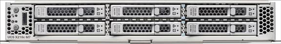
▪ Cisco UCS X210c M7 servers with 5th Generation Intel Xeon Scalable Processors with up to 64 cores per processor and up to 8TB of DDR-5600 DIMMs
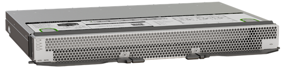
▪ Cisco UCS X440p PCIe Nodes
▪ Cisco UCS 9416 X-Fabric Module
▪ NVIDIA L40 GPUs
▪ Red Hat OpenShift Container Platform 4.15
▪ Ansible orchestration of Cisco UCS and Hitachi VSP resources
▪ Hitachi Storage Provider for VMware vCenter 3.7.4
▪ Hitachi Ops Center release version 11.0.1
▪ Hitachi Storage Plug-in version 4.10
Deployment Hardware and Software
This chapter contains the following:
The deployment hardware and software incorporate the base architecture defined in the Cisco and Hitachi Adaptive Solutions with Cisco UCSX, VMware 8U1, and Hitachi VSP 5600 Design Guide with some additions and upgrades.
The Adaptive Solutions Virtual Server Infrastructure consists of a high-performance Fibre Channel network built using the following hardware components:
▪ Cisco UCS X9508 Chassis with Cisco UCSX-I-9108-100G Intelligent Fabric Modules (IFMs) and up to eight Cisco UCS X210c M7 Compute Nodes with options for 4th and 5th Generation Intel Xeon Scalable CPUs.
▪ Cisco UCS X440p PCIe Nodes with NVIDIA L40 GPUs.
▪ Fifth-generation Cisco UCS 6536 Fabric Interconnects to support 100GbE, 25GbE, and 32GFC connectivity as needed.
▪ High-speed Cisco NX-OS-based Nexus 93600CD-GX switching design to support up to 100GE.
▪ Hitachi 5600 Virtual Storage Platform all flash storage system with 32G Fibre Channel connectivity.
▪ Cisco MDS 9124V switches to support Fibre Channel storage configuration.
The software components of the solution consist of:
▪ Cisco Intersight SaaS platform to deploy, maintain, and support the Adaptive Solutions infrastructure, giving visibility to the compute, network and storage in the architecture.
▪ Cisco Intersight Assist Virtual Appliance to connect the Hitachi VSP 5600, VMware vCenter, and Cisco Nexus and MDS switches with Cisco Intersight.
▪ Hitachi Ops Center Administrator is an infrastructure management solution that unifies storage provisioning, data protection, and storage management.
▪ Hitachi Ops Center API Configuration Manager to help connect the Hitachi VSP 5600 to the Intersight platform and to use Hitachi Storage Plug-in for vCenter.
▪ Hitachi Storage Modules for Red Hat Ansible to help provision VSP host groups and volumes.
▪ Hitachi Storage Plug-in for VMware vCenter to integrate VSP system information and provisioning operations into the vSphere Web Client.
▪ VMware vCenter to set up and manage the virtual infrastructure as well as Cisco Intersight integration.
Figure 1 shows the validated hardware components and connections used in the Adaptive Solutions Virtual Server Infrastructure design.
Figure 1. Adaptive Solutions Virtual Server Infrastructure Physical Topology
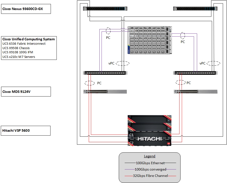
The reference hardware configuration includes:
▪ Two Cisco Nexus 93600CD-GX Switches in Cisco NX-OS mode provide the switching fabric.
▪ Two Cisco UCS 6536 Fabric Interconnects (FI) provide chassis connectivity. One 100 Gigabit Ethernet port from each FI, configured as a Port-Channel, is connected to each 93600CD-GX. Four FC ports are connected to the Cisco MDS 9124V switches via breakout using 32-Gbps Fibre Channel connections configured as a single port channel for SAN connectivity.
▪ One Cisco UCS X9508 Chassis connects to fabric interconnects using Cisco UCSX 9108-100G Intelligent Fabric Modules (IFMs), where four 100 Gigabit Ethernet ports are used on each IFM to connect to the appropriate FI. If additional bandwidth is required, all eight 100G ports can be utilized.
▪ The Cisco MDS 9124V sits between the compute and storage delivering 32Gbps Fibre Channel connectivity, as well as interfacing to resources present in an existing data center.
▪ The Hitachi VSP 5600 controllers connect with two 32Gbps FC ports from each controller to each Cisco MDS 9124V for delivering data to the SAN network.
Table 1 lists the software revisions for various components of the solution.
| Layer |
Device |
Image |
Comments |
| Network |
Cisco Nexus 93600CD-GXNX-OS |
10.3(5)M |
|
| Cisco MDS 9124V |
9.4(1a) |
Requires SMART Licensing |
|
| Compute |
Cisco UCS Fabric Interconnect 6536 and UCS 9108-100G IFM |
4.3(4) |
|
| Cisco UCS X210c M7 |
5.2(1.240010) |
|
|
| Cisco UCS Tools |
1.3.3-1OEM |
|
|
| VMware ESXi nfnic FC Driver |
5.0.0.43 |
Supports FC-NVMe |
|
| VMware ESXi nenic Ethernet Driver |
2.0.11.0 |
|
|
| VMware ESXi |
8.0 Update 2 |
Build 21813344 included in Cisco Custom ISO, updated with patch 8.0 Update 1c |
|
| VMware vCenter Appliance |
8.0 Update 2c |
Build 23504390 |
|
| Cisco Intersight Assist Appliance |
1.0.9-588 |
1.0.9-588 initially installed and then automatically upgraded |
|
| Storage |
Hitachi VSP 5600 |
SVOS 90-09-22-00/00 |
|
| Hitachi Ops Center Administrator/CM Rest |
11.01 |
|
|
| Hitachi Storage Provider for VMware vCenter |
3.7.4 |
|
|
| Hitachi Storage Plugin for VMware vCenter |
4.10 |
|
|
| Hitachi Storage Modules for Red Hat Ansible |
3.0.x |
|
The information in this section is provided as a reference for cabling the physical equipment in the environment. This includes a diagram for each layer of infrastructure detailing the local and remote port locations.
Note: If you modify the validated architecture, see the Cisco Hardware Compatibility Matrix and the Hitachi Product Compatibility Guide for guidance.
This document assumes that out-of-band management ports are plugged into an existing management infrastructure at the deployment site. These interfaces will be used in various configuration steps.
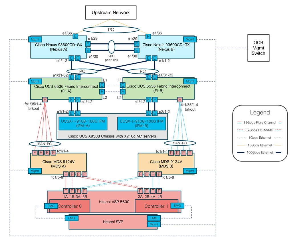
Figure 2 details the cable connections used in the validation lab for the Adaptive Solutions VSI topology based on the Cisco UCS 6536 fabric interconnect and the Hitachi VSP 5600. Four 32Gb uplinks via breakout connect as SAN port-channels from each Cisco UCS Fabric Interconnect to the MDS switches, and a total of eight 32Gb links connect the MDS switches to the VSP controller ports. 100Gb links connect the Cisco UCS Fabric Interconnects as port-channels to the Cisco Nexus 93600CD-GX switch pair’s vPCs, while upstream of the Nexus switches, 400G uplink connections are possible for the model. Additional 1Gb management connections will be needed for an out-of-band network switch that sits apart from the Adaptive Solutions infrastructure. Each Cisco UCS fabric interconnect and Cisco Nexus switch is connected to the out-of-band network switch, and the VSP is front-ended by the SVP, which has a connection to the out-of-band network switch. Layer 3 network connectivity is required between the Out-of-Band (OOB) and In-Band (IB) Management Subnets.
Figure 2. Adaptive Solutions Cabling with Cisco UCS 6536 Fabric Interconnect
Technology Overview of New Components
This chapter contains the following:
▪ 5th Gen Intel Xeon Scalable Processors
▪ Cisco UCS X9416 X-Fabric Module
▪ OpenShift Container Platform
▪ Hitachi Storage Modules for Red Hat Ansible
▪ Hitachi Storage Plug-in for VMware vCenter
This architecture directly extends from the Virtual Server Infrastructure defined in the Cisco and Hitachi Adaptive Solutions with Cisco UCSX, VMware 8U1, and Hitachi VSP 5600 Design Guide. The full list of solution elements found in the base architecture can be found here: https://www.cisco.com/c/en/us/td/docs/unified_computing/ucs/UCS_CVDs/hitachi_adaptive_vmware_vsp_design.html#TechnologyOverview.
The following are new elements to the design discussed in this document.
5th Gen Intel Xeon Scalable Processors
The Intel 5th generation Xeon Scalable processors expand the power and deployment options of the Cisco UCS X210c Compute Nodes. You can see a 21% average performance gain and a 36% increase in performance for watts used with these new processors when compared to previous generations of Intel Xeon processors.
More information on the 5th Gen Intel Xeon Scalable Processors can be found here: https://www.intel.com/content/www/us/en/products/docs/processors/xeon/5th-gen-xeon-scalable-processors.html
Cisco UCS X9416 X-Fabric Module
The Cisco UCS X9416 X-Fabric modules provide high speed PCIe connectors to Cisco UCS X210c M6 and M7 Compute Nodes. This allows the Cisco UCS X-Series Servers to have the density and efficiency of a blade solution but have expandability options as needed.
Computing nodes are connected through rear mezzanine ports into the fabric module slots directly for PCIe connectivity to expansion nodes without a midplane. More information on the Cisco UCS X9416 X-Fabric can be found here: https://www.cisco.com/c/en/us/products/collateral/servers-unified-computing/ucs-x-series-modular-system/ucs-x-fabric-here-aag.html
The Cisco UCS X440p PCIe Node provides 2 or 4 PCIe slots for GPUs that will connect to an adjacent compute node through the Cisco UCS X-Fabric. All GPUs within the PCIe node must be of the same type.
The PCIe nodes must be positioned in alternating chassis slots with the compute nodes in a consistent pattern of the PCIe nodes residing on either all even, or all odd slot IDs. More information on the Cisco UCS X440p PCIe Node can be found here: https://www.cisco.com/c/en/us/products/collateral/servers-unified-computing/ucs-x-series-modular-system/ucs-x440p-pcle-node-ds.html
The NVIDIA L40 supports the latest hardware-accelerated ray tracing, revolutionary AI features, advanced shading, and powerful simulation capabilities for a wide range of graphics and compute use cases in data center and edge server deployments.

More information on the NVIDIA L40 GPU can be found here: https://www.nvidia.com/content/dam/en-zz/Solutions/Data-Center/datasheets/L-40/product-brief-L40.pdf
Red Hat OpenShift Container Platform (OCP) is a hybrid cloud platform as a service for building and managing containerized applications. Deployment, visibility, and orchestration is available through API, CLI, and console tools.

More information on Red Hat OCP can be found here: https://www.redhat.com/en/technologies/cloud-computing/openshift/container-platform
Red Hat Ansible is an open-source tool for automation, configuration management, application software deployment, and for Infrastructure as Code (IaC). When used for IaC, Ansible manages endpoints and infrastructure components in an inventory file, formatted in YAML or INI.

Red Hat Ansible is free to use and can be extended for greater enterprise level value with the subscription based Red Hat Ansible Automation Platform. More information on Ansible can be found here: https://www.ansible.com/
Hitachi Storage Modules for Red Hat Ansible
You can enhance your day 1 storage management experience with the integration of Hitachi Vantara Storage Modules into Ansible. These modules include configuration and management modules for on-premises storage and public cloud storage. Additional information on Hitachi Storage Modules can be found here: https://docs.hitachivantara.com/v/u/en-us/adapters-and-drivers/3.0.x/mk-92adptr149
Hitachi Storage Plug-in for VMware vCenter
Hitachi Storage Plug-in for VMware vCenter integrates Hitachi Storage system information and provisioning operations into the vSphere Client from a common user interface. Additional information can be found here: https://docs.hitachivantara.com/v/u/en-us/adapters-and-drivers/4.10.x/mk-92adptr047

Solution Design
This chapter contains the following:
This Adaptive Solutions OpenShift Container Platform design implements a virtualized OCP deployment on top of the previously discussed Virtual Server Infrastructure (VSI) design for Cisco UCS receiving Fibre Channel based storage from the Hitachi VSP 5600 shown in Figure 3. Cisco Intersight and Hitachi Ops Center are the primary components for configuration and visibility into the infrastructure. The Hitachi Storage Plug-in for VMware vCenter has been added to the CI infrastructure and enables the VMware vSphere Web Client to provision and manage VSP volumes. For more information, see the appendix in the Hitachi Storage Plug-in for VMware vCenter. The appendix also includes configuration examples using Ansible for both compute and storage.
Figure 3. Red Hat OCP hosted within Adaptive Solutions VSI
The IP network is based on the Cisco Nexus 9600CD-GX switch and delivers resilient 100GE connectivity utilizing NX-OS features to include:
▪ Feature interface-vans—Allows for VLAN IP interfaces to be configured within the switch as gateways.
▪ Feature HSRP—Allows for Hot Standby Routing Protocol configuration for high availability.
▪ Feature LACP—Allows for the utilization of Link Aggregation Control Protocol (802.3ad) by the port channels configured on the switch.
▪ Feature VPC—Virtual Port-Channel (vPC) presents the two Nexus switches as a single “logical” port channel to the connecting upstream or downstream device.
▪ Feature LLDP—Link Layer Discovery Protocol (LLDP), a vendor-neutral device discovery protocol, allows the discovery of both Cisco devices and devices from other sources.
▪ Feature NX-API—NX-API improves the accessibility of CLI by making it available outside of the switch by using HTTP/HTTPS. This feature helps with configuring the Cisco Nexus switch remotely using the automation framework.
▪ Feature UDLD—Enables unidirectional link detection for various interfaces.
Connectivity from the Cisco Nexus switches is through the Cisco UCS 6536 Fabric Interconnects as shown in Figure 4. This figure shows the configuration of the validated environment, when considering a production environment, redundant upstream switches could be supported.
Figure 4. Cisco Nexus connectivity to the Cisco UCS 6536 Fabric Interconnects and upstream network
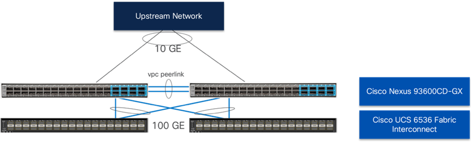
Within certain L2 traffic patterns between servers within the UCS domain, the traffic will be pinned to stay within one side of the fabric interconnects to avoid unnecessary northbound hops up to the Nexus.
The storage network implements Fibre Channel for FC-SCSI and FC-NVMe traffic with the 64G capable Cisco MDS 9124V. Some of the features incorporated with the MDS in this design include:
▪ Feature NPIV — N port identifier virtualization (NPIV) provides a means to assign multiple FC IDs to a single N port.
▪ Feature fport-channel-trunk — F-port-channel-trunks allow for the fabric log-ins from the NPV switch to be virtualized over the port channel. This provides nondisruptive redundancy should individual member links fail.
▪ Enhanced Device Alias – a feature that allows device aliases (a name for a WWPN) to be used in zones instead of WWPNs, making zones more readable. Also, if a WWPN for a vHBA or Hitachi VSP port changes, the device alias can be changed, and this change will carry over into all zones that use the device alias instead of changing WWPNs in all zones.
▪ Smart-Zoning — a feature that reduces the number of TCAM entries and administrative overhead by identifying the initiators and targets in the environment.
Connections between the MDS bridging the compute to the storage are shown in Figure 5.
Figure 5. Fibre Channel connectivity through the MDS 9124V
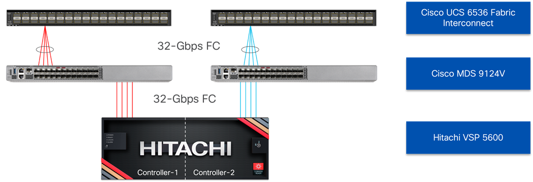
The logical view of the IP and FC network extends the physical into the virtual connections as they are positioned to support the OCP solution shown in Figure 6. The VIC adapters of the Cisco UCS X210c present virtual NICs and virtual HBAs as it carries the converged traffic within the solution. Primary IP network traffic is passed through the ingress and egress IPs that were set on the IB-Mgmt network, but this can be changed to fit the customer implementation.
Figure 6. Logical view of LAN and SAN connectivity
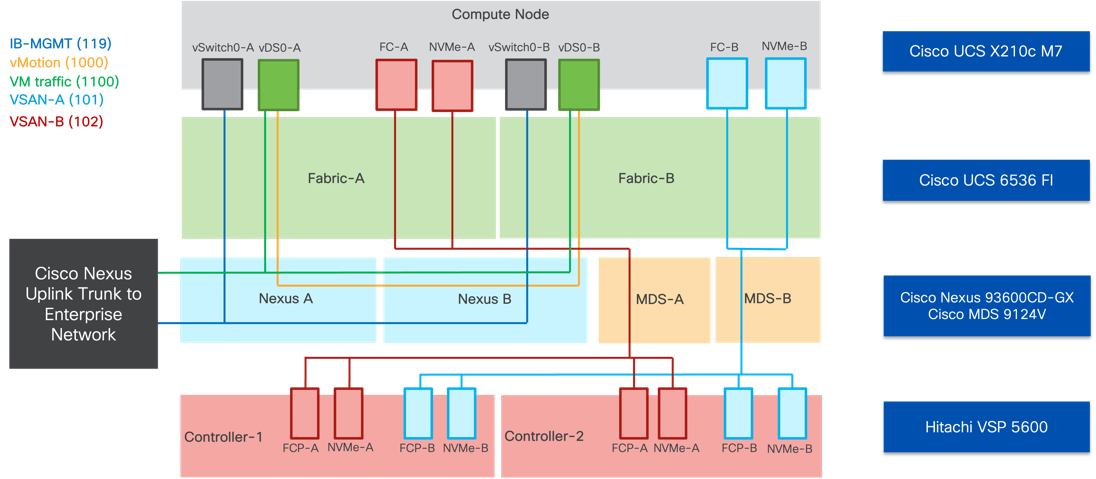
For the tested environment, all OCP traffic was carried through the underlay of the physical network through the IB-MGMT network shown above. Customizations can be made to incorporate other dedicated networks, but the Control Nodes, Worker Nodes, Ingress and Egress were accommodated by IB-MGMT.
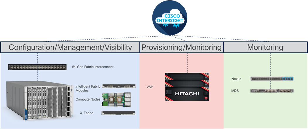
The Cisco UCS X-Series Modular System delivers a high-density compute system configured and managed through Cisco Intersight. This SaaS delivered platform gives scalability to UCS at a global level with the potential for a unified view and control of all compute for an organization through a single interface that also gives that same visibility to Hitachi storage and Cisco networking with Nexus and MDS switches. Intersight is accessible through secure SSO and a REST API to automate the management of Intersight connected devices across multiple data centers. Figure 7 provides a summary of Cisco Intersight within this design.
Figure 7. Cisco Intersight control and visibility across the architecture
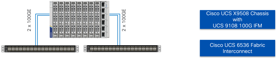
The Cisco UCS X-Series M7 X210c Compute Nodes in this design incorporate offerings of both 4th Generation along with 5th Generation Intel Xeon Scalable processors. The density of computing power available in these CPUs provides the opportunity to deliver more computing power per physical rack space and power consumed compared to previous generations of computing. The Intelligent Fabric Module (IFM) connects up to 8 100G connections of converged traffic to each fabric interconnect, which are automatically configured as port channels for resiliency. Figure 8 illustrates the connections from the IFM to the servers are direct, without a need for a backplane.
Figure 8. FI connectivity to Chassis through IFM
Through Cisco Intersight, the fabric interconnects oversee the configuration and control of the compute nodes through server policies and pools of identifying information, such as UUIDs, WWPNs, and MAC addresses that are incorporated as server profiles that can be provisioned uniformly and at scale through server profile templates. Along with the configuration, the fabric interconnects control the converged traffic sent to the servers that it receives from either the upstream network, east-west between other servers, or through the MDS SAN network from the Hitachi VSP.
This converged traffic is received by the 5th Generation UCS VIC adapters that present virtual adapters of NICs that can receive VLAN tagged traffic and virtual HBAs. The WWPN identities held by these virtual HBAs are registered in the zoning on the MDS as well as in host groups within Ops Center to associate them as initiators for the targets held by the VSP for the association of FC boot LUNs and data LUNs of both FC-SCSI and FC-NVMe.
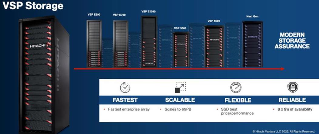
A key element in the successful deployment of a container platform is having a robust and flexible infrastructure that can meet the wide variety of requirements in a highly dynamic environment. The Cisco and Hitachi Adaptive Solution for CI with Red Hat OpenShift Container Platform (OCP) provides highly available, predictable, and high-performance infrastructures for container applications running on virtual nodes with persistent storage on the Hitachi VSP. The Hitachi VSP is a highly scalable, true enterprise-class storage system that can virtualize external storage and provide virtual partitioning, and quality of service for diverse workload consolidation. With the industry’s only 100 percent data availability guarantee, the Virtual Storage Platform delivers the highest uptime and flexibility for your block-level storage needs.
Figure 9. Hitachi VSP Storage Family
For more information on Hitachi Vantara Virtual Storage Platform, see: https://www.cisco.com/c/en/us/td/docs/unified_computing/ucs/UCS_CVDs/hitachi_adaptive_vmware_vsp_design.html
In addition to configuring the VSP 5600 through Ops Center Administrator, two additional tools are now available to provide flexibility for the provisioning and management of storage for the Adaptive Solution for CI. These tools include:
▪ Hitachi Storage Modules for Red Hat Ansible
▪ Hitachi Storage Plug-in for VMware vCenter
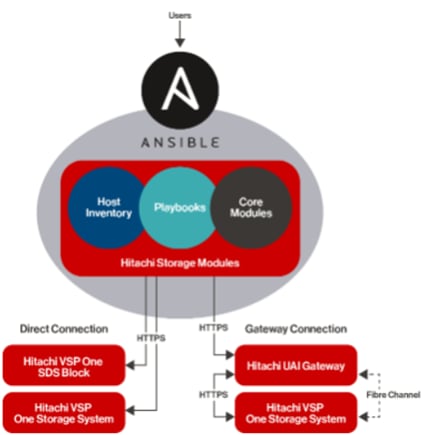
The Hitachi Storage Modules for Red Hat Ansible enables IT and data center administrators to consistently and reliably provision and manage the Hitachi Virtual Storage Platform (VSP) from Red Hat Ansible playbooks. You can use these storage modules with playbooks that you create to manage your infrastructure with either a direct connection to the storage system or using a Unified API Infrastructure (UAI) gateway connection. Within the context of this CVD, the Hitachi VSP 5600 was managed through a direct connection.
Figure 10 shows the available Ansible Control Node connectivity options to the Hitachi VSP 5600.
Figure 10. Hitachi Vantara Storage Modules for Red Hat Ansible Connectivity Options
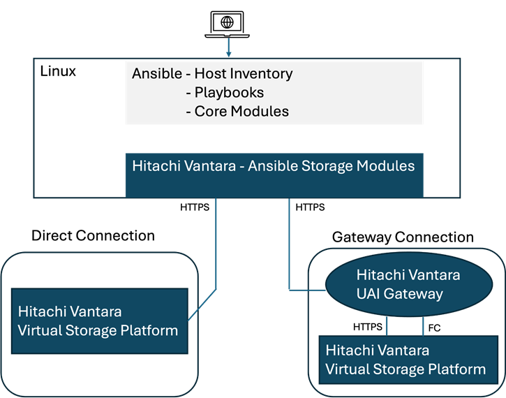
The Hitachi Storage Modules for Red Hat include various software modules supporting storage configuration (host groups and LUNs) and storage management. Refer to the Hitachi Vantara Virtual Storage Platform Ansible Support Appendix for deployment and usage information.
Hitachi Storage Plug-in for VMware vCenter (referred to as Hitachi Storage Plug-in in this document) integrates Hitachi storage system information and provisioning operations into the vSphere Web Client. This integration allows VMware product administrators to perform storage provisioning operations from within the VMware user interface, which offers greater convenience than switching between VMware and Hitachi management software to perform common operations involving both. The Hitachi Storage Plug-In simplifies the Day-1 configuration and management of the VSP using the FC-SCSI protocol to provide Virtual Machine File System (VMFS) datastore volumes.
The Hitachi Storage Plug-in provides the following features:
▪ View: The View function displays the storage system information registered in Hitachi Storage Plug-in, the datastore on the ESXi host using the storage system, and virtual machine information.
▪ Provision Datastore: The Provision Datastore function creates an LDEV/volume used as a datastore for a Virtual Machine File System (VMFS), a Network File System (NFS), and for Raw Device Mapping objects (RDMs) by a storage system registered in Hitachi Storage Plug-in.
▪ Delete Datastore: The Delete Datastore function removes datastores created using Hitachi Storage Plug-in and the LDEVs or volumes of storage systems corresponding to a datastore. This feature does not support datastores and LDEVs/volumes created without using Hitachi Storage Plug-in.
For deployment and usage information, go to section Hitachi Storage Plug-in for VMware vCenter in the Appendix.
Figure 11 illustrates the capability overview of Red Hat OCP backed by Hitachi VSP storage on top of Cisco and Hitachi Adaptive Solutions for CI.
Figure 11. Red Hat OCP on Cisco Hitachi Adaptive Solutions
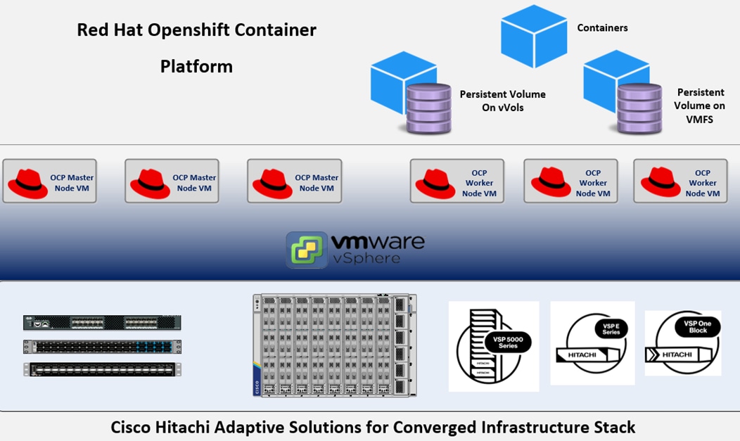
This guide offers a VSP storage solution that can be used to meet most deployment configurations that require persistent storage service for containers (applications) in a Red Hat OCP virtualized environment. This solution integrates the VMware Container Storage Interface (CSI) with Cloud Native Storage (CNS) using the Hitachi Storage Provider for VMware vCenter (VASA) software. The Hitachi VSP provides Fibre Channel connectivity in the form of FC-SCSI (VMFS and vVols), and FC-NVMe (VMFS).
vSphere Cloud Native Storage
Cloud Native Storage (CNS) integrates vSphere and OCP and offers capabilities to create and manage container volumes deployed in a vSphere environment. CNS consists of two components, a CNS component in vCenter Server and vSphere CSI driver in OCP. CNS enables vSphere and vSphere storage (VMFS and vVols) to run stateful applications. CNS enables access to this data path for OCP and brings information about OCP volume and pod abstractions to vSphere. CNS uses several components to work with vSphere storage including VMFS or vVols provided by the Hitachi Storage Provider for VMware vCenter. After you create persistent volumes (PVs), you can review them and their backing virtual disks in the vSphere Client and monitor their storage policy compliance.
vSphere Cloud Storage Interface
The Container Storage Interface (CSI) driver is installed in the Kubernetes cluster and can provide persistent storage to worker nodes within the OCP cluster. Administrators can use VMware through the csi.vsphere.vmware.com driver which enables PV creation from VMFS datastores backed by the Hitachi VSP. A Persistent Volume Claim (PVC) is created that references an available StorageClass, which maps to a vSphere storage policy-based management (SPBM) policy. A first-class disk (FCD) is created within vSphere, and a resultant PV is presented to the OpenShift layer from the CSI driver. The FCD is then mounted to the pod when requested for use as a PV. The vSphere CSI driver has different components that provide an interface used by the Container Orchestrators such as OpenShift to manage the lifecycle of vSphere volumes. It is also used to create volumes, expand and delete volumes, snapshot volumes and restore, attach, and detach volumes to the cluster worker node VMs, and use bind mounts for the volumes inside the pods.
Note: The vSphere CSI driver does not support cloning PVCs.
Hitachi Storage Provider for VMware vCenter (VASA)
Hitachi Storage Provider for VMware vCenter (VASA) enables VASA APIs for storage awareness to be used with Hitachi storage systems. VASA enables policies to be made by making the storage attribute information available in vSphere. VASA enables organizations to deploy Hitachi storage infrastructure with VMware vSphere Virtual Volumes (vVols) to bring customers on a reliable enterprise journey to a software-defined, policy-controlled datacenter. Hitachi storage policy-based management (SPBM) enables automated provisioning of virtual machines (VMs) and quicker adjustment to business changes. Virtual infrastructure (VI) administrators can make changes to policies to reflect changes in their business environment, dynamically matching storage policy requirements for VMs to available storage pools and services. The vVols solution reduces the operational burden between VI administrators and storage administrators with an efficient collaboration framework leading to faster and better VM and application services provisioning.
VASA makes this possible in two ways:
▪ VMware vSphere vVols
This function is the VASA component of VMware vVols that enables vVols to be used with supported Hitachi storage systems in a 1-to-1 mapping, enabling greater insight into virtual machine performance.
▪ VMware VMFS
VASA enables storage capability information and alert notifications related to VMFS file systems to be generated automatically and displayed in vCenter Server.
Hitachi VSP vSphere OCP Persistent Storage Options
Table 2 lists the supported Hitachi VSP integration beginning with the OCP Deployment Type, supported Storage Type, and the supported storage for container persistent storage.
Table 2. Supported Hitachi VSP Integration
| Red Hat OpenShift Container Platform |
||
| Deployment Type |
Storage Type |
Hitachi Persistent Storage Provider Compatibility |
| VM (all virtualized OCP Infrastructure |
Cloud Native Storage (CNS) |
Container Storage Interface (vVols + VMFS) |
Red Hat OCP will have a requirement of DNS and DHCP to bring up the cluster. Internet access is needed for the Installer Provisioned Infrastructure (IPI) method followed in our example, but the cluster can be built from Red Hat using an offline method for local/air gapped placements. An LDAP source like Active Directory can be used for setting up the OAuth, as well as an internal OAuth server can optionally be setup.
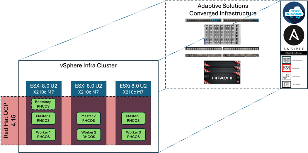
The physical underlay of the converged infrastructure as it maps to the OCP installation is shown in Figure 12.
Figure 12. Cisco UCS compute and VSP storage underlay mapping to OCP
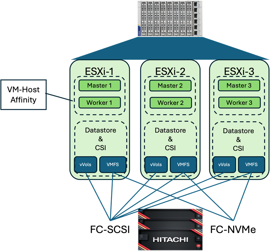
The OCP environment in this design is hosted within three VMware vSphere hosts residing on Cisco UCS X210c Compute Nodes. With the deployment completed, nodes are distributed across the hosts, keeping the respective master and worker nodes isolated from each other using vSphere DRS VM-Host Affinity rules as shown in Figure 12. Within the deployment, the storage is allocated for the OCP components from the Hitachi VSP 5600. This places the nodes on VM datastores, and provisions Persistent Virtual Storage (PVC) using the vSphere Container Storage Integration (CSI) on either vVols or VMFS for persistent storage needs of the deployed containers.
The network design used by OCP is shown in Figure 13. It receives and sends traffic through the Cisco UCS VIC adapters, that are teamed with the route based on originating virtual port algorithm, for any traffic external to the cluster, or must travel between nodes that are not residing on the same host. The cluster uses the OCP default Container Network Interface (CNI) specification, with the nodes implementing Open Virtual Networking (OVN) with an Open Virtual Switch (OVS) that spans across the nodes. Pods receive an OVN allocated IP, and containers residing within the pod will share that IP.
Figure 13. Container networking mapping to the connectivity provided by the Cisco UCS VIC and VMware vSphere installation
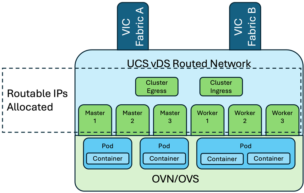
The East/West traffic between nodes will pass with an overlay created with Generic Network Virtualization Encapsulation (GENEVE) implemented by OVN. Connectivity and services for pods and containers is handled with OVN constructs giving a potentially more human readable than presentation than was found with the previous OpenShift SDN. Alternate CNI options are available, including one from Cisco that is incorporated through Cisco ACI to give a common interface to datacenter networking down into containers.
Red Hat recommendations for OpenShift v4 on VMware vSphere include the following:
▪ The overall CPU over-commitment ratio for all pods to physical cores available in the cluster should not exceed 1.8.
▪ Memory usage for all pods should not exceed .9 of the physical memory available in a cluster.
▪ Etcd hosted on the control-plane nodes is used to store the OCP cluster state and is usually the most latency sensitive component. For etcd, it is important to always have low latency.
▪ Deploy OpenShift on a dedicated vSphere cluster to reduce competition for physical resources between different applications.
▪ Apply anti-affinity rules for the master node and worker nodes.
▪ OCP supports compute only vMotion and should follow VMware best practices. vMotion has a short duration during which the VM is not available and is a risk for a latency sensitive workload. vMotion for a VM hosting an OCP node should only be triggered when unavoidable. Only a single OCP master node should be migrated to a different host at a time. Ensure sufficient time for all etcd cluster members to synchronize before initiating vMotion for another master node.
▪ Storage vMotion is not supported. If you are using vSphere datastores in your pods, migrating a VM across datastores can cause invalid references within the OCP persistent volume (PV) objects that can result in data loss.
▪ Worker nodes should have spare capacity for failover situations. In the event of a node failure, OCP will attempt to schedule the lost pods to another node. It is important to test fail-over scenarios. especially if a vSphere cluster is used for OCP and VMs are configured for HA, which could lead to latency.
Implementation
This chapter contains the following:
▪ Preparation for Installation
▪ Configure vSphere VM Storage Policies
▪ Red Hat OCP Storage Configuration
▪ Red Hat OCP Storage Management
This chapter explains the deployment of the Red Hat OCP on an existing Adaptive Solutions Converged Infrastructure VSI placement, detailed in this CVD deployment guide: https://www.cisco.com/c/en/us/td/docs/unified_computing/ucs/UCS_CVDs/hitachi_adaptive_vmware_vsp.html. The primary Red Hat source for installing OCP for this architecture can be found here: https://docs.redhat.com/en/documentation/openshift_container_platform/4.15/html/installing/installing-on-vsphere#preparing-to-install-on-vsphere
The OCP placement has these additional dependencies in place at installation time:
▪ DNS Server
From a primary DNS domain in our setup of adaptive-solutions.local, a subdomain is created of:
as-ocp.adaptive-solutions.local
◦ Within this subdomain there are two initial A record (Host) entries of:
api.as-ocp.adaptive-solutions.local
*.apps.as-ocp.adaptive-solutions.local
▪ DHCP Server
A DHCP scope will be needed to at least support the provisioning of the master and worker nodes of the cluster. Additionally, the following scope options will be needed:
▪ 003 Router
▪ 004 Timer Server
▪ 006 DNS Servers
▪ 015 DNS Domain Name
▪ Red Hat Credentials
Red Hat credentials are needed to log in to https://console.redhat.com for provisioning OCP. A subscription is not needed for a 60 day trial but will be needed for any production placement.
The installation for Red Hat OCP on VMware vSphere will go through some of the initial setup from https://console.redhat.com and the deployment being invoked from an installation host.
Procedure 1. Start installation
Step 1. Open a browser and log in to https://console.redhat.com.
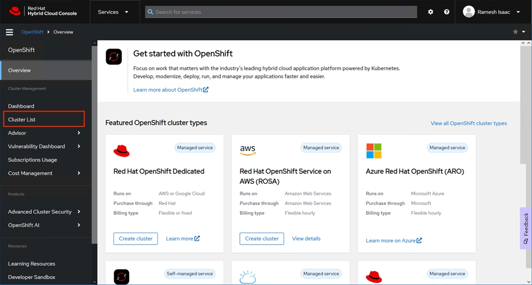
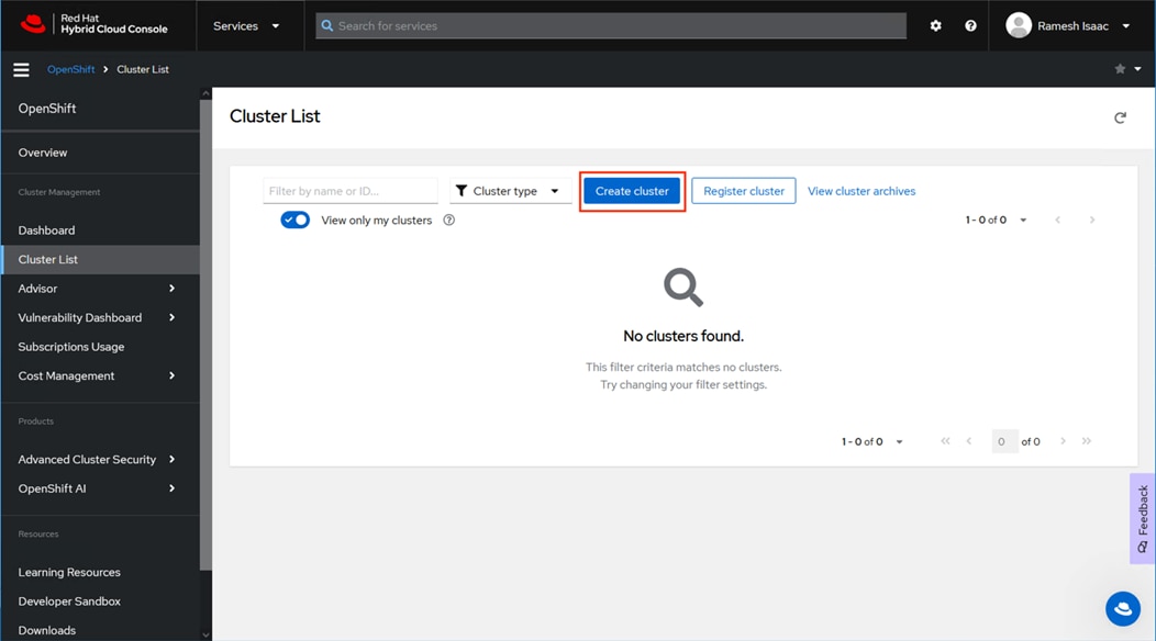
Step 2. Click Cluster List from the options in the left pane and click Create cluster.
Step 3. Click Datacenter.
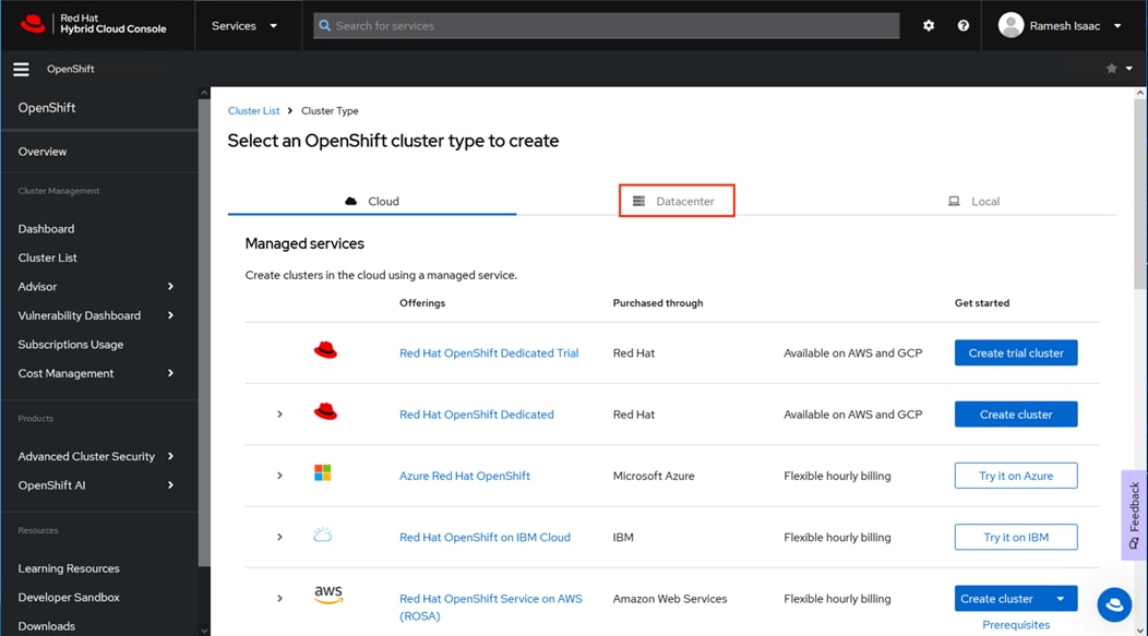
Step 4. Scroll down in the resulting page and click the vSphere option.
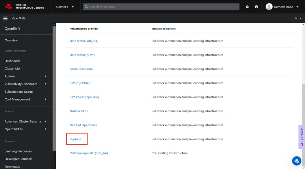
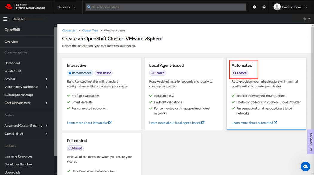
Step 5. Click the Automated option.
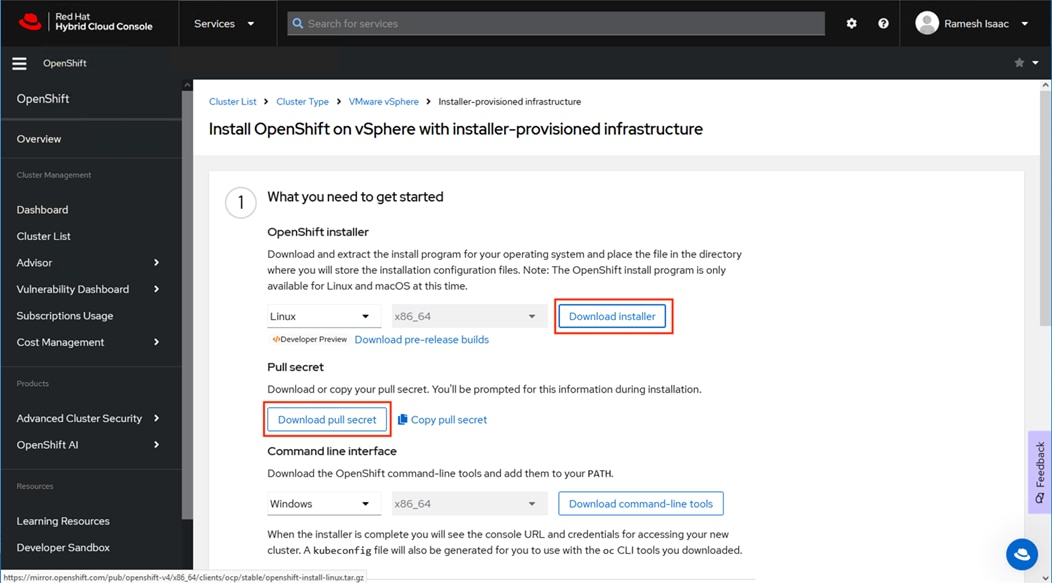
Step 6. Click Download installer to save the compressed tar bundle for the installer and click Download pull secret to save a text copy of the pull secret. If manually recording, click Copy pull secret.
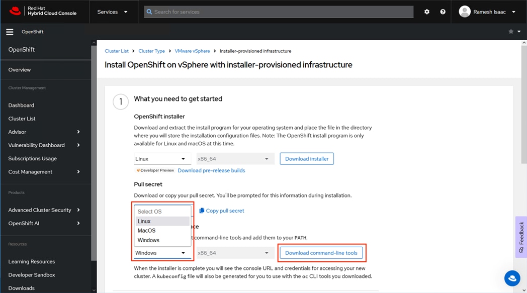
Step 7. Select the appropriate OS from the drop-down list for the Command line interface and click Download command-line tools to save.
Step 8. Copy the installer, pull secret, and command-line tools to the installation host.
Step 9. Connect to the installation host and run the following commands, changing destinations and names as needed:
mkdir bin install
gunzip openshift-client-linux.tar.gz openshift-install-linux.tar.gz
tar xf openshift-install-linux.tar -C install
tar xf openshift-client-linux.tar -C bin
Step 10. Gather the X.509 certificates from vCenter: https://vc.adaptive-solutions.local/certs/download.zip substituting the appropriate vCenter address for vc.adaptive-solutions.local.

Step 11. Copy the download.zip file to the installer and unzip it.
Step 12. From the installer, run the following commands:
sudo cp lin/* /etc/pki/ca-trust/source/anchors
sudo update-ca-trust extract
Step 13. From the install host, run openshift-install to create the cluster, providing options for the dialogue when prompted:
[as-control@as-control ~]$ openshift-install create cluster
? SSH Public Key /home/as-control/.ssh/id_rsa.pub
? Platform vsphere
? vCenter vc.adaptive-solutions.local
? Username administrator@vsphere.local
? Password [? for help] *********
INFO Connecting to vCenter vc.adaptive-solutions.local
INFO Defaulting to only available datacenter: AS-VSI
? Cluster /AS-VSI/host/8.0U1-M7
? Default Datastore /AS-VSI/datastore/DS1
? Network IB-Mgmt-119
? Virtual IP Address for API 10.1.168.49
? Virtual IP Address for Ingress 10.1.168.48
? Base Domain adaptive-solutions.local
? Cluster Name as-ocp
? Pull Secret [? for help] *************************************************************************INFO Creating infrastructure resources...
INFO Waiting up to 20m0s (until 5:21PM EDT) for the Kubernetes API at https://api.as-ocp.adaptive-solutions.local:6443...
INFO API v1.28.9+416ecaf up
INFO Waiting up to 1h0m0s (until 6:03PM EDT) for bootstrapping to complete...
INFO Destroying the bootstrap resources...
INFO Waiting up to 40m0s (until 5:55PM EDT) for the cluster at https://api.as-ocp.adaptive-solutions.local:6443 to initialize...
INFO Waiting up to 30m0s (until 5:53PM EDT) to ensure each cluster operator has finished progressing...
INFO All cluster operators have completed progressing
INFO Checking to see if there is a route at openshift-console/console...
INFO Install complete!
INFO To access the cluster as the system:admin user when using 'oc', run 'export KUBECONFIG=/home/as-control/auth/kubeconfig'
INFO Access the OpenShift web-console here: https://console-openshift-console.apps.as-ocp.adaptive-solutions.local
INFO Login to the console with user: "kubeadmin", and password: "pXXXX-sXXXX-hXXXX-nXXXX"
INFO Time elapsed: 30m35s
Step 14. Connect using CLI with the log in information provided at the end of the installation dialogue or connect to https://console-openshift-console.apps.as-ocp.adaptive-solutions.local and log in with the kubeadmin user.
Configure vSphere VM Storage Policies
VMware vSphere VM storage policies must be configured before creating a storage class within Red Hat OpenShift Container Management Platform (OCP). This section covers how to create storage policies for both VMFS and vVols datastores backed by Hitachi Virtual Storage Platform (VSP) with capabilities translated down using the VASA APIs.
Storage managed capabilities for both VMFS and vVols Datastores can be defined using the Hitachi Storage Provider for VMware vCenter. These managed capabilities identify the characteristics for a VMFS LDEV or a vVols storage container and are visible within vCenter. Defined capabilities include Performance IOPs and Performance Latency and Availability. For defining the managed capabilities for Hitachi Vantara VSP 5600 LDEVs or vVols Storage Containers, see: https://www.cisco.com/c/en/us/td/docs/unified_computing/ucs/UCS_CVDs/hitachi_adaptive_vmware_vsp.html
VM Storage Policy for VMFS
Procedure 1. Create a VMware vSphere VM storage policy for a VMFS datastore
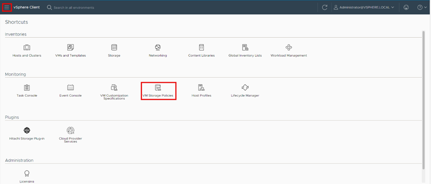
Step 1. Log in to the VMware vSphere Client.
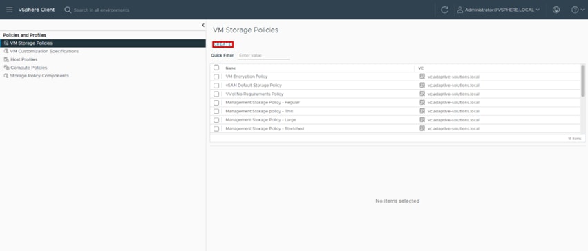
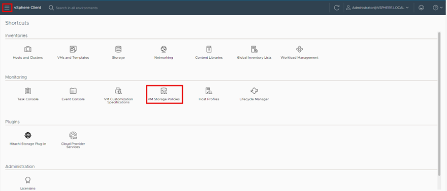
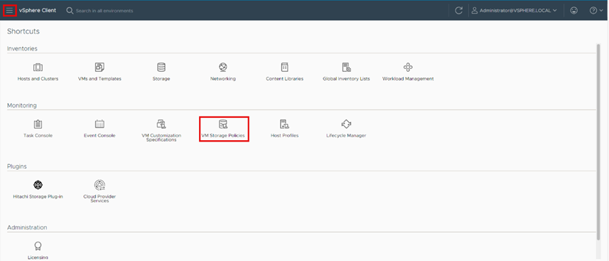
Step 2. Select Shortcuts and click VM Storage Policies.
Step 3. Click Create.
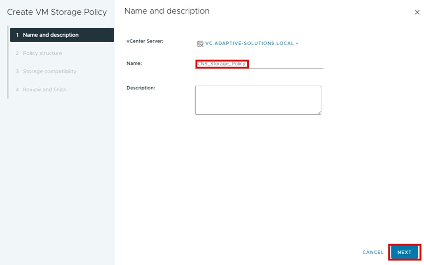
Step 4. Define a policy Name and click NEXT.
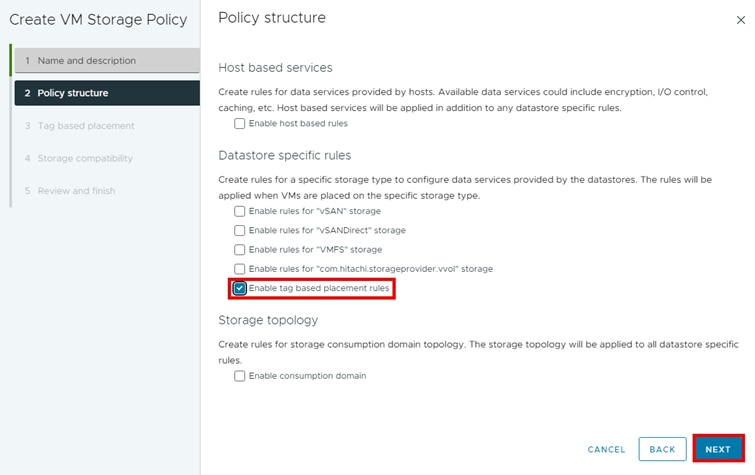
Step 5. Under Datastore specific rules, select Enable tag-based placement rules and click NEXT.
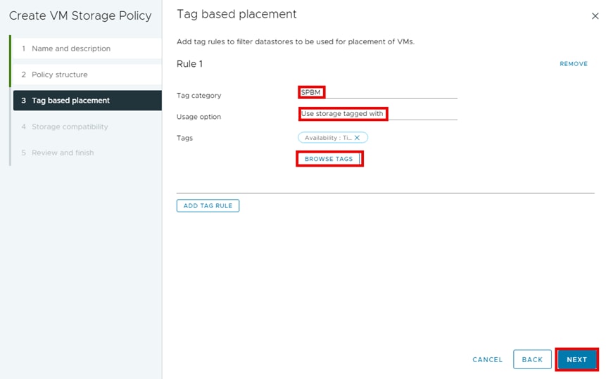
Step 6. From Tag based placement, select the following and then click NEXT.
a. Tag category: SPBM
b. Usage options: Use storage tagged with
c. Tags: BROWSE TAGS
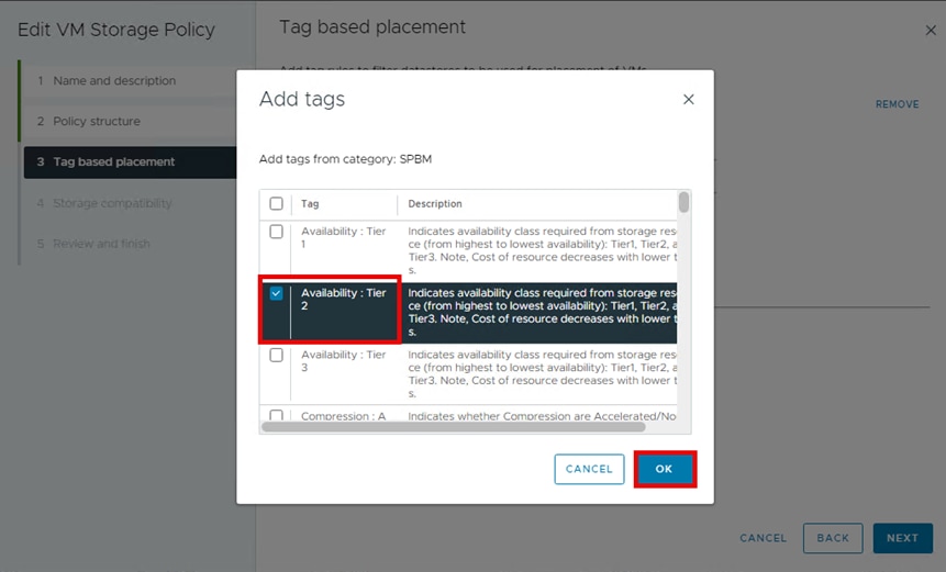
Step 7. Select the applicable storage tags for a VMFS Datastore that the storage administrator has defined using the Storage Provider for VMware vCenter, or that has been natively tagged using vCenter and then click OK.
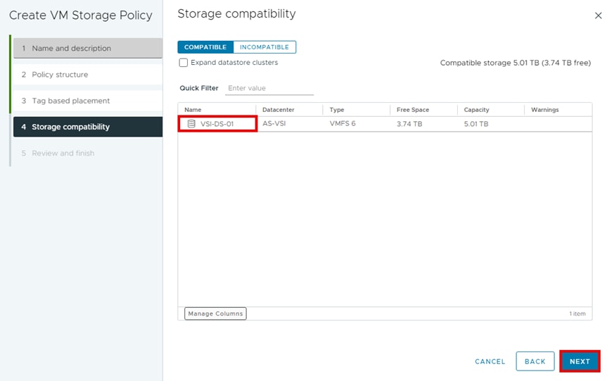
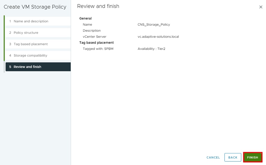
Step 8. From the Storage compatibility window, you will see the datastores that match the tags that you enabled in the previous step. Under Name, select the datastore and click NEXT.
Step 9. From the Review and finish tab, click FINISH.
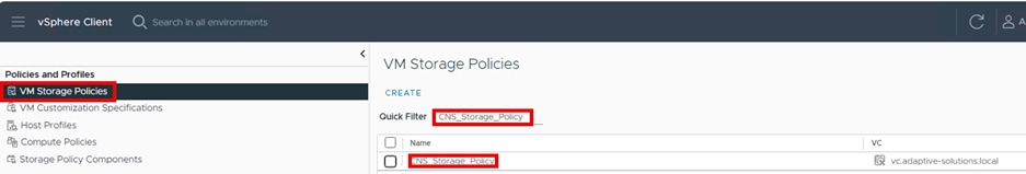
Step 10. Select Shortcuts and click VM Storage Policies.
Step 11. Confirm the creation of the new Storage Policy by selecting VM Storage Polices and using the Quick Filter and searching for CNS_Storage_Policy.
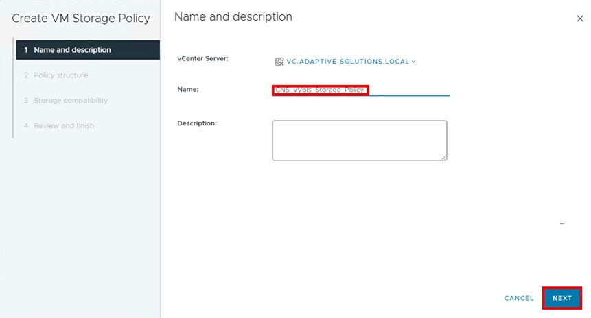
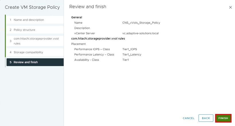
Procedure 1. Create a VMware VM storage policy for a vVols datastore
Step 1. Log in to the VMware vSphere Client.
Step 2. Select Shortcuts and click VM Storage Policies.
Step 3. Click Create.

Step 4. Define a Name and click NEXT.
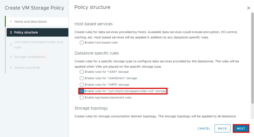
Step 5. For Datastore specific rules, select Enable rules for “com.hitachi.storageprovider.vvol” storage and click NEXT.
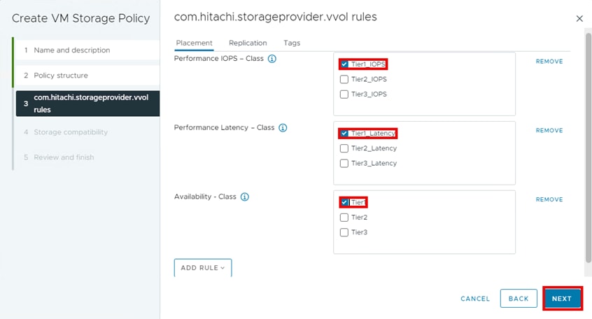
Step 6. From the com.hitachi.storageprovider.vvol rules pane, from the Placement tab, select Tier1_IOPS, Tier1_Latency, Tier1, and click NEXT.
Step 7. From the Storage compatibility window, you will see datastores that match the com.hitachi.storageprovider.vvol placement requirements that you selected in the previous step. Under Name, select the datastore and click NEXT.
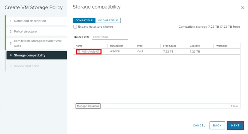
Step 8. From the Review and finish pane, click FINISH.
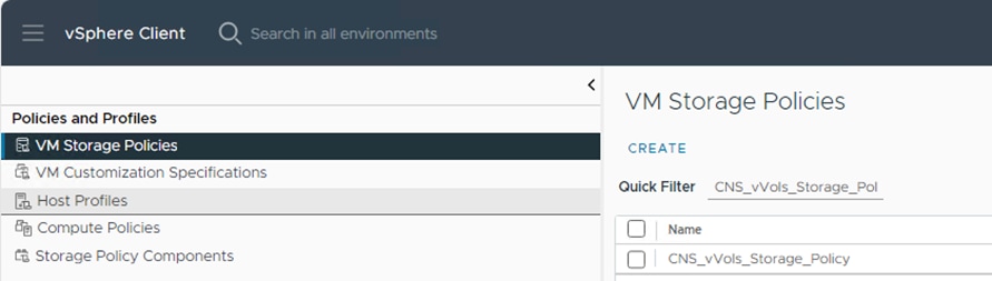
Step 9. Confirm the vSphere Storage Policy has been created.
Red Hat OCP Storage Configuration
Red Hat OCP provides a CLI for administrators to deploy Persistent Volumes (PVs) with containerized applications. This section describes prerequisite storage operations to provide persistent storage to the environment backed by Hitachi VSP.
OCP persistent storage is supported on the Hitachi VSP with FC-SCSI, FC-NVMe, and vVols storage. Within OCP, Storage Classes are created to match a specific vCenter Storage Policy name assigned to a datastore with the suitable type of storage (FC-SCSI, FC-NVMe, or vVols).
Note: Verify that you have completed the previous procedures in this guide before continuing.
The following OCP CLI sections steps document configuring the storage requirements for an OCP Pod and are common across the different storage protocols:
▪ Create an OCP Storage Class for each of the vSphere Storage Policy associated with a specific type of Datastore (VMFS or vVols)
A Storage Class provides a way for administrators to describe the classes of storage they offer which can be requested through the OCP interface. Each class contains fields for administrators to define the provisioner, parameter, and reclaim policy which are used for Persistent Volume (PV) creation via Persistent Volume Claims (PVCs). The provisioner parameter in a virtual environment backed by Hitachi storage on top of VMware would use the CSI provisioner csi.vsphere.vmware.com. Storage Classes also have specific names and are called out when creating PVCs. When administrators create Storage Class objects, these objects cannot be updated once they have been created.
▪ Create a PVC associated with each OCP Storage Class
One of the storage resources that the OCP platform orchestrates is Persistent Storage via Persistent Volumes (PV). PVs are resources in the Kubernetes cluster that have a lifecycle independent of any pod that uses a PV. This is a type of volume on the host machine that stores persistent data. PVs provide storage resources in a cluster, which allows the storage resource to persist even when the pods that use them are removed. PVs can be statically or dynamically provisioned, and they can be customized for performance, size, and access mode. PVs can be attached to pods via a Persistent Volume Claim (PVC), that is, a request for the resource that acts as a claim to check for available resources.
▪ Create a Pod associated with each PVC. In OCP, a pod consists of either a single or multiple containers and are packaged together to maximize resource sharing benefits
OCP Storage Configuration Section for vSphere VMFS Datastores
The directions in the section apply to VMFS datastores supported via FC-SCSI as well as FC-NVMe.
Procedure 1. Create Storage Class - VMFS
Step 1. Confirm that the VMware storage policy backed by a VMFS datastore has been created and has compatible storage.
Step 2. Log in to the OCP CLI using valid user credentials.
Step 3. Use the parameters listed below and create the following file “StorageClass_VMFS.yaml” to configure the Storage Class for a vCenter VMFS datastore.
Parameters:
a. Define the kind parameter as StorageClass.
b. Define the API version used.
c. Define an applicable StorageClass name for OCP “csi-sc”.
d. Optionally, select whether this is a default StorageClass.
e. Define the provisioner used. For CNS, the default is “csi.vsphere.vmare.com”.
f. Set the StoragePolicyName to the VMware storage policy name defined in vCenter for VMFS datastore “CNS_Storage_Policy”.
g. Set the reclaim Policy as “Delete”.
h. Set the volumeBindingMode as “Immediate”.
StorageClass_VMFS.yaml file:
kind: StorageClass (a)
apiVersion: storage.k8s.io/v1 (b)
metadata:
name: csi-sc (c)
annotations:
storageclass.kubernetes.io/is-default-class: 'false' (d)
provisioner: csi.vsphere.vmware.com (e)
parameters:
StoragePolicyName: CNS_Storage_Policy (f)
allowVolumeExpansion: true
reclaimPolicy: Delete (g)
volumeBindingMode: Immediate (h)
Step 4. Create the Storage Class for the VMFS datastore using the following command:
oc create -f StorageClass_VMFS.yaml
Step 5. Verify the Storage Class for the VMFS datastore “csi-sc” has been created with the following command:
oc get sc
[as-control@as-control ~]$ oc get sc
NAME PROVISIONER RECLAIMPOLICY VOLUMEBINDINGMODE ALLOWVOLUMEEXPANSION AGE
csi-sc csi.vsphere.vmware.com Delete Immediate true 4s
thin-csi (default) csi.vsphere.vmware.com Delete WaitForFirstConsumer true 5d19h
Procedure 2. Create PVC -VMFS
Before creating a PVC, verify that an appropriate StorageClass exists. Additionally, confirm that the VMware storage policy backed by a VMFS datastore is created and has compatible storage. Use the following OCP CLI procedure to deploy a PVC.
Step 1. Use the parameters listed below and create the following file “pvc.yaml” to configure the PVC for a vCenter VMFS datastore.
Parameters:
a. Define the API version used.
b. Define the kind parameter as “PersistentVolumeClaim”.
c. Select an applicable PersistentVolumeClaim name “pvc-vmfs”.
d. Set the accessModes to “ReadWriteOnce”.
e. Set the storage size to “10Gi”.
f. Set the storageClassName to the OCP Storage Class defined for VMFS “csi-sc”.
pvc.yaml file:
apiVersion: v1 (a)
kind: PersistentVolumeClaim (b)
metadata:
name: pvc-vmfs (c)
spec:
accessModes:
- ReadWriteOnce (d)
resources:
requests:
storage: 10Gi (e)
storageClassName: csi-sc (f)
Step 2. Create the PVC for the VMFS datastore using the following command:
oc create -f pvc.yaml
Step 3. Verify the PVC using the VMFS datastore has been created with the following command:
oc get pvc
[as-control@as-control home]$ oc get pvc
NAME STATUS VOLUME CAPACITY ACCESS MODES STORAGECLASS AGE
pvc-vmfs Bound pvc-26c28f19-ce53-4f3c-97c2-6f27d142e5e1 10Gi RWO csi-sc 17s
Procedure 3. Create Pod - VMFS
Before creating a PVC verify that an appropriate Storage Class, and PVC exist. Confirm that the VMware storage policy backed by a VMFS datastore is created and has compatible storage. Use the following OCP CLI procedure to configure a Pod.
Step 1. Use the parameters listed below and create the following file “PODBox_vmfs.yaml” to configure an OCP Pod for a vCenter VMFS datastore:
Parameters:
a. Define the API version used.
b. Define the kind parameter as “Pod”.
c. Assign a name to the Pod “pod-box”.
d. Assign a name to the container “my-busybox”.
e. Use the following image for the container “busybox”.
f. Under volumeMounts - Specify the mountPath “/data”.
g. Under volumeMounts – Specify name “sample-volume”.
h. Set command to ["sleep", "1000000"].
i. For imagePullPolicy, pull the image if it does not already exist on the node “IfNotPresent”.
j. Under volumes, assign the name “sample-volume”.
k. Set the claimName to the PVC for VMFS “pvc-vmfs”.
PODBox_vmfs.yaml file
apiVersion: v1 (a)
kind: Pod (b)
metadata:
name: pod-box (c)
spec:
containers:
- name: my-busybox (d)
image: busybox (e)
volumeMounts:
- mountPath: "/data" (f)
name: sample-volume (g)
command: ["sleep", "1000000"] (h)
imagePullPolicy: IfNotPresent (i)
volumes:
- name: sample-volume (j)
persistentVolumeClaim:
claimName: pvc-vmfs (k)
Step 2. Create the Pod using the following command:
oc create -f PODBox_vmfs.yaml
Step 3. Verify the POD has been created using the following command:
oc get pod
[as-control@as-control ~]$ oc get pod
NAME READY STATUS RESTARTS AGE
pod-box 1/1 Running 0 33s
OCP Storage Configuration Section for vVols
Procedure 1. Create Storage Class – vVols
Use the following OCP CLI procedure to create a Storage Class.
Step 1. Confirm that the VMware storage policy backed by a vVols datastore has been created and has compatible storage.
Step 2. Log in to the OCP CLI using valid user credentials.
Step 3. Use the parameters listed below and create the following file “StorageClass_vvols.yaml” to configure the Storage Class for a vCenter VMFS datastore.
Parameters:
a. Define the kind parameter as “StorageClass”.
b. Define the API version used.
c. Define an applicable StorageClass name “csi-vvols-sc”.
d. Optionally select whether this is a default StorageClass “false”.
e. Define the provisioner used. For CNS, the default is “csi.vsphere.vmare.com”.
f. Set the StoragePolicyName to the VMware storage policy within vCenter for a vVols datastore “CNS_vVols_Storage_Policy”.
g. Set allowVolumeExpansion to “true”.
h. Set the reclaim Policy as “Delete”.
i. Set the volumeBindingMode as “Immediate”.
StorageClass_vvols.yaml file:
kind: StorageClass (a)
apiVersion: storage.k8s.io/v1 (b)
metadata:
name: csi-vvols-sc (c)
annotations:
storageclass.kubernetes.io/is-default-class: 'false' (d)
provisioner: csi.vsphere.vmware.com (e)
parameters:
StoragePolicyName: CNS_vVols_Storage_Policy (f)
allowVolumeExpansion: true (g)
reclaimPolicy: Delete (h)
volumeBindingMode: Immediate (i)
Step 4. Create the Storage Class for the vVols datastore using the following command:
oc create -f StorageClass_vvols.yaml
Step 5. Verify the Storage Class for the vVols datastore “csi-vvols-sc” has been created with the following command:
oc get sc
[as-control@as-control ~]$ oc get sc
NAME PROVISIONER RECLAIMPOLICY VOLUMEBINDINGMODE ALLOWVOLUMEEXPANSION AGE
csi-sc csi.vsphere.vmware.com Delete Immediate true 37m
csi-vvols-sc csi.vsphere.vmware.com Delete Immediate true 3s
thin-csi (default) csi.vsphere.vmware.com Delete WaitForFirstConsumer true 5d20h
Procedure 2. Create PVC - vVols
Before creating a PVC verify that an appropriate StorageClass exists. Confirm that the VMware storage policy backed by a vVols datastore is created and has compatible storage. Use the following OCP CLI procedure to deploy a PVC.
Step 1. Use the parameters listed below and create the following file “pvc_vvols.yaml” to configure the PVC for a vCenter VMFS datastore.
Parameters:
a. Define the API version used.
b. Define the kind parameter as “PersistentVolumeClaim”.
c. Select an applicable PersistentVolumeClaim name “pvc-vvols”.
d. Set the accessModes to “ReadWriteOnce”.
e. Set the storage size to “10Gi”.
f. Set the storageClassName to the OCP Storage Class defined for vVols “csi-vvols-sc”.
File pvc_vvols.yaml
apiVersion: v1 (a)
kind: PersistentVolumeClaim (b)
metadata:
name: pvc-vvols (c)
spec:
accessModes:
- ReadWriteOnce (d)
resources:
requests:
storage: 10Gi (e)
storageClassName: csi-vvols-sc (f)
Step 2. Create the PVC for the VMFS datastore using the following command:
oc create -f pvc_vvols.yaml
Step 3. Verify the PVC using the vVols datastore has been created with the following command:
oc get pvc
[as-control@as-control ~]$ oc get pvc
NAME STATUS VOLUME CAPACITY ACCESS MODES STORAGECLASS AGE
pvc-from-snapshot Bound pvc-2ca034e8-cf96-451c-88c2-244a8c100968 20Gi RWO csi-sc 28m
pvc-vmfs Bound pvc-ff2f3539-7e08-4dbd-a883-6ecaafa5017b 20Gi RWO csi-sc 58m
pvc-vvols Bound pvc-4556b046-8945-46d7-a36a-b13dbc942a93 10Gi RWO csi-vvols-sc 12s
Procedure 3. Create Pod - vVols
Before creating a PVC verify that an appropriate Storage Class and PVC exist. Confirm that the VMware storage policy backed by a vVols datastore is created and has compatible storage. Use the following OCP CLI procedure to configure a Pod.
Step 1. Use the parameters listed below and create the following file “PODBox1_vvols.yaml” to configure an OCP Pod for a vCenter vVols datastore.
Parameters:
a. Define the API version used.
b. Define the kind parameter as Pod.
c. Assign a name to the Pod “pod-box1”.
d. Assign a name to the container “my-busybox1”.
e. Use the following image for the container “busybox”.
f. Under volumeMounts, specify where external storage volumes are mounted within the container “/data”.
g. Under volumeMounts, assign a name to the volume “sample-volume”.
h. Set command to “["sleep", "1000000"]”.
i. For imagePullPolicy, pull the image if it does not already exist on the node “IfNotPresent”.
j. Under volumes, assign the name “sample-volume”.
k. Assign a name to the volume.
l. Set the persistent volume to the PVC for vVols “pvc-vvols”.
PODBox1_vvols.yaml file
apiVersion: v1 (a)
kind: Pod (b)
metadata:
name: pod-box1 (c)
spec:
containers:
- name: my-busybox1 (d)
image: busybox (e)
volumeMounts:
- mountPath: "/data" (f)
name: sample-volume (g)
command: ["sleep", "1000000"] (h)
imagePullPolicy: IfNotPresent (i)
volumes:
- name: sample-volume (j)
persistentVolumeClaim:
claimName: pvc-vvols (k)
Step 2. Create the Pod using the following command:
oc create -f PODBox1_vvols.yaml
Step 3. Display the POD using the following command:
oc get pod
[as-control@as-control ~]$ oc get pod
NAME READY STATUS RESTARTS AGE
pod-box 1/1 Running 0 59m
pod-box1 1/1 Running 0 11s
Red Hat OCP Storage Management
The following OCP CLI sections document managing a PV and are common across the different storage protocols:
▪ Expand a PVC
The vSphere CSI Driver allows volume expansion of deployed PVs. Before expanding a PV, confirm that the StorageClass has volume expansion parameter allowVolumeExpansion: true. Kubernetes supports offline and online modes of volume expansion. When the PVC is used by a pod and is mounted on a node, the volume expansion operation is categorized as online. In all other cases, it is an offline expansion.
Note: PV capacity cannot be reduced.
Note: When expanding volume capacity there is no need to delete and redeploy Pods.
▪ Snapshot a PVC
A snapshot is a point-in-time image of a volume and can be used to duplicate the previous state of an existing volume or to provision a new pre-populated volume. A Snapshot Class must be created before creating the PVC snapshot.
▪ Restore a PVC to a new PVC
OCP Storage Management for VMFS
Procedure 1. Expand an OCP Persistent Volume - VMFS
Step 1. Display the PVC by using the following command:
oc get pvc
[as-control@as-control ~]$ oc get pvc
NAME CAPACITY ACCESS MODES RECLAIM POLICY STATUS CLAIM STORAGECLASS REASON AGE
pvc-ff2f3539-7e08-4dbd-a883-6ecaafa5017b 10Gi RWO Delete Bound default/pvc-vmfs csi-sc 10s
Step 2. Display the Pod by using the following command:
oc get pod
[as-control@as-control ~]$ oc get pod
NAME READY STATUS RESTARTS AGE
pod-box 1/1 Running 0 33s
Step 3. Patch the PVC in online mode to increase the storage size from 10Gi to 20Gi using the following command:
oc patch pvc pvc-vmfs -p '{"spec": {"resources": {"requests": {"storage": "20Gi"}}}}'
Step 4. Display the PVC with the following command to verify the expansion “oc get pvc”:
[as-control@as-control ~]$ oc get pvc
NAME STATUS VOLUME CAPACITY ACCESS MODES STORAGECLASS AGE
pvc-vmfs Bound pvc-ff2f3539-7e08-4dbd-a883-6ecaafa5017b 20Gi RWO csi-sc 4m53s
Procedure 2. Create Persistent Volume Snapshots - VMFS
Step 1. Create the snapshot class yaml file named “volumesnapshotclass_vmfs.yaml”.
Step 2. Edit the “volumesnapshotclass_vmfs.yaml” using the following parameters:
Parameters:
a. Define the API version.
b. Define the kind variable as “VolumeSnapShotClass”.
c. Assign a name to the snapshot class “snapshotclass-csi”.
d. Set the driver to “csi.vpshere.vmware.com”.
e. Set the deletionPolicy to “Delete”.
volumesnapshotclass_vmfs.yaml file
apiVersion: snapshot.storage.k8s.io/v1 (a)
kind: VolumeSnapshotClass (b)
metadata:
name: snapshotclass-csi (c)
driver: csi.vsphere.vmware.com (d)
deletionPolicy: Delete (e)
Step 3. Create the snapshot class for the VMFS PVC using the following command:
oc create -f volumesnapshotclass_vmfs.yaml
Step 4. Display the snapshot class using the following command:
oc get volumesnapshotclass
[as-control@as-control ~]$ oc get volumesnapshotclass
NAME DRIVER DELETIONPOLICY AGE
csi-vsphere-vsc csi.vsphere.vmware.com Delete 5d19h
snapshotclass-csi csi.vsphere.vmware.com Delete 13m
Step 5. Create the PVC snapshot yaml file named “volumesnapshot_vmfs.yaml”.
Step 6. Edit the “volumesnapshot_vmfs.yaml” using the following parameters:
Parameters:
a. Define the API version.
b. Define the kind variable as “VolumeSnapShot”.
c. Assign a name to the snapshot.
d. Set the volumeSnapshotClassName to “snapshotclass-csi”.
e. Set the persistentVolumeClaimName to “pvc-vmfs”.
volumesnapshot_vmfs.yaml file
apiVersion: snapshot.storage.k8s.io/v1 (a)
kind: VolumeSnapshot (b)
metadata:
name: snapshot-csi (c)
spec:
volumeSnapshotClassName: snapshotclass-csi (d)
source:
persistentVolumeClaimName: pvc-vmfs (e)
Step 7. Create the persistent volume snapshot with the following command:
oc create -f volumesnapshot_vmfs.yaml
Step 8. Verify the volume snapshot using the following command:
oc get volumesnapshot
[as-control@as-control ~]$ oc get volumesnapshot
NAME READYTOUSE SOURCEPVC SOURCESNAPSHOTCONTENT RESTORESIZE SNAPSHOTCLASS SNAPSHOTCONTENT CREATIONTIME AGE
snapshot-csi true pvc-vmfs 20Gi snapshotclass-csi snapcontent-88de34a8-7d7c-4a24-9418-2923c6e50d6d 10s 14s
Procedure 3. Restore Persistent Volume Snapshots to a new PVC – VMFS
Step 1. Restore the PV snapshot as a new PVC by creating a yaml file named “pvc_from_snapshot_vmfs.yaml” using the following parameters:
Parameters:
a. Define the API version.
b. Define the kind variable as “PersistentVolumeClaim”.
c. Assign a name for the new PVC “pvc-from-snapshot”.
d. Set the datasource name to “snapshotclass-csi”.
e. Set the datasource kind to “VolumeSnapshot”.
f. Set the datasource apiGroup to “snapshot.storage.k8s.io”.
g. Set accessModes to “ReadWriteOnce”.
h. Set storage to “20Gi”.
i. Set StorageClassName to “csi-sc”.
pvc_from_snapshot_vmfs.yaml file
apiVersion: v1 (a)
kind: PersistentVolumeClaim (b)
metadata:
name: pvc-from-snapshot (c)
spec:
dataSource:
name: snapshot-csi (d)
kind: VolumeSnapshot (e)
apiGroup: snapshot.storage.k8s.io (f)
accessModes:
- ReadWriteOnce (g)
resources:
requests:
storage: 20Gi (h)
storageClassName: csi-sc (i)
Step 2. Restore the snapshot using the following command:
oc create -f pvc pvc_from_snapshot_vmfs.yaml
Step 3. Verify the new PVC has been created by using the following command:
oc get pvc
[as-control@as-control ~]$ oc get pvc
NAME STATUS VOLUME CAPACITY ACCESS MODES STORAGECLASS AGE
pvc-from-snapshot Bound pvc-2ca034e8-cf96-451c-88c2-244a8c100968 20Gi RWO csi-sc 8s
pvc-vmfs Bound pvc-ff2f3539-7e08-4dbd-a883-6ecaafa5017b 20Gi RWO csi-sc 30m
OCP Storage Management for vVols
Procedure 1. Expand an OCP Persistent Volume - vVols
Step 1. Display the PVC by using the following command:
oc get pvc
[as-control@as-control ~]$ oc get pvc
NAME STATUS VOLUME CAPACITY ACCESS MODES STORAGECLASS AGE
pvc-from-snapshot Bound pvc-2ca034e8-cf96-451c-88c2-244a8c100968 20Gi RWO csi-sc 28m
pvc-vmfs Bound pvc-ff2f3539-7e08-4dbd-a883-6ecaafa5017b 20Gi RWO csi-sc 58m
pvc-vvols Bound pvc-4556b046-8945-46d7-a36a-b13dbc942a93 10Gi RWO csi-vvols-sc 12s
Step 2. Display the Pod by using the following command:
oc get pod
[as-control@as-control ~]$ oc get pod
NAME READY STATUS RESTARTS AGE
pod-box 1/1 Running 0 59m
pod-box1 1/1 Running 0 11s
Step 3. Patch the PVC in online mode to increase the storage size from 10Gi to 20Gi using the following command:
oc patch pvc pvc-vvols -p '{"spec": {"resources": {"requests": {"storage": "20Gi"}}}}'
Step 4. Display the PVC with the following command to verify the expansion:
oc get pvc
[as-control@as-control ~]$ oc get pvc
NAME STATUS VOLUME CAPACITY ACCESS MODES STORAGECLASS AGE
pvc-from-snapshot Bound pvc-2ca034e8-cf96-451c-88c2-244a8c100968 20Gi RWO csi-sc 33m
pvc-vmfs Bound pvc-ff2f3539-7e08-4dbd-a883-6ecaafa5017b 20Gi RWO csi-sc 63m
pvc-vvols Bound pvc-4556b046-8945-46d7-a36a-b13dbc942a93 20Gi RWO csi-vvols-sc 4m31s
Procedure 2. Create Persistent Volume Snapshots - vVols
Step 1. Create the snapshot class yaml file named “volumesnapshotclass_vvols.yaml”.
Step 2. Edit the “volumesnapshotclass_vvols.yaml” using the following parameters:
Parameters:
a. Define the API version.
b. Define the kind variable as “VolumeSnapShotClass”.
c. Assign a name to the snapshot class “snapshotclass-csi-vvols”.
d. Set the driver to “csi.vpshere.vmware.com”.
e. Set the deletionPolicy to “Delete”.
volumesnapshotclass_vvols.yaml file
apiVersion: snapshot.storage.k8s.io/v1 (a)
kind: VolumeSnapshotClass (b)
metadata:
name: snapshotclass-csi-vvols (c)
driver: csi.vsphere.vmware.com (d)
deletionPolicy: Delete (e)
Step 3. Create the snapshot class for the VMFS PVC using the following command:
oc create -f volumesnapshotclass_vvols.yaml
Step 4. Display the snapshot class using the following command:
oc get volumesnapshotclass
[as-control@as-control ~]$ oc get volumesnapshotclass
NAME DRIVER DELETIONPOLICY AGE
csi-vsphere-vsc csi.vsphere.vmware.com Delete 5d20h
snapshotclass-csi csi.vsphere.vmware.com Delete 56m
snapshotclass-csi-vvols csi.vsphere.vmware.com Delete 12s
[as-control@as-control ~]$ oc create -f volumesnapshot_vvols.yaml
Step 5. Create the PVC snapshot yaml file named “volumesnapshot_vvols.yaml”.
Step 6. Edit the “volumesnapshot_vvols.yaml” using the following parameters:
Parameters:
a. Define the apiVersion
b. Define the kind variable as “VolumeSnapShot”.
c. Assign a name to the snapshot “snapshot-csi-vvols”.
d. Set the volumeSnapshotClassName to “snapshotclass-csi-vvols”.
e. Set the persistentVolumeClaimName to “pvc-vvols”.
volumesnapshot_vvols.yaml file
apiVersion: snapshot.storage.k8s.io/v1 (a)
kind: VolumeSnapshot (b)
metadata:
name: snapshot-csi-vvols (c)
spec:
volumeSnapshotClassName: snapshotclass-csi-vvols (d)
source:
persistentVolumeClaimName: pvc-vvols (e)
Step 7. Create the persistent volume snapshot with the following command:
oc create -f volumesnapshot_vvols.yaml
Step 8. Verify the volume snapshot using the following command:
oc get volumesnapshot
[as-control@as-control ~]$ oc get volumesnapshot
NAME READYTOUSE SOURCEPVC SOURCESNAPSHOTCONTENT RESTORESIZE SNAPSHOTCLASS SNAPSHOTCONTENT CREATIONTIME AGE
snapshot-csi true pvc-vmfs 20Gi snapshotclass-csi snapcontent-88de34a8-7d7c-4a24-9418-2923c6e50d6d 35m 35m
snapshot-csi-vvols true pvc-vvols 20Gi snapshotclass-csi-vvols snapcontent-93478f44-0e73-436d-99d8-d93efa82dafc 20s 31s
Procedure 3. Restore Persistent Volume Snapshots to a new PVC – vVols
Step 1. Restore the PV snapshot as a new PVC by creating a yaml file named “pvc_from_snapshot_vvols.yaml” using the following parameters:
Parameters:
a. Define the API version.
b. Define the kind variable as “PersistentVolumeClaim”.
c. Assign a name for the new PVC “pvc-from-snapshot-vvols”.
d. Set the datasource name to “snapshotclass-csi-vvols”.
e. Set the datasource kind to “VolumeSnapshot”.
f. Set the datasource apiGroup to “snapshot.storage.k8s.io”.
g. Set accessModes to “ReadWriteOnce”
h. Set storage to “20Gi”
i. Set StorageClassName to “csi-vvols-sc”
pvc_from_snapshot_vvols.yaml file
apiVersion: v1 (a)
kind: PersistentVolumeClaim (b)
metadata:
name: pvc-from-snapshot-vvols (c)
spec:
dataSource:
name: snapshot-csi-vvols (d)
kind: VolumeSnapshot (e)
apiGroup: snapshot.storage.k8s.io (f)
accessModes:
- ReadWriteOnce (g)
resources:
requests:
storage: 20Gi (h)
storageClassName: csi-vvols-sc (i)
Step 2. Restore the snapshot using the following command:
oc create -f pvc pvc_from_snapshot_vvols.yaml
Step 3. Verify the new PVC has been created by using the following command:
oc get pvc
[as-control@as-control ~]$ oc get pvc
NAME STATUS VOLUME CAPACITY ACCESS MODES STORAGECLASS AGE
pvc-from-snapshot Bound pvc-2ca034e8-cf96-451c-88c2-244a8c100968 20Gi RWO csi-sc 38m
pvc-from-snapshot-vvols Bound pvc-8fb5c950-8fa8-4ee7-8f93-66652abce102 20Gi RWO csi-vvols-sc 20s
pvc-vmfs Bound pvc-ff2f3539-7e08-4dbd-a883-6ecaafa5017b 20Gi RWO csi-sc 68m
pvc-vvols Bound pvc-4556b046-8945-46d7-a36a-b13dbc942a93 20Gi RWO csi-vvols-sc 9m57s
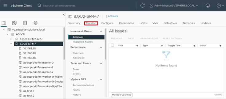
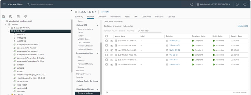
Procedure 4. View Persistent Storage on VMware vCenter
After you have deployed the PVCs, you can view them natively within VMware vCenter. From this vantage point, administrators can view other information about the object such as PVC ID, PVC name, as well as namespace information which relates to the OCP deployment. Use the following procedure to view container volumes within vCenter.
Step 1. Log into the VMware vSphere Client.
Step 2. Select Inventory.
Step 3. Click your vCenter cluster.
Step 4. Select the Monitor tab.
Step 5. From the Monitor navigation tree, go to Cloud Native Storage > Container Volumes.
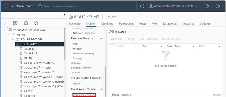
The workspace presents the PVCs deployed using OCP, and you can view the Volume Name, Datastore, Compliance Status, Health Status, and Capacity Quota.
Ramesh Isaac, Technical Marketing Engineer, Cisco Systems, Inc.
Ramesh Isaac is a Technical Marketing Engineer in the Cisco UCS Data Center Solutions Group. Ramesh has worked in the data center and mixed-use lab settings for over 25 years. He started in information technology supporting UNIX environments and focused on designing and implementing multi-tenant virtualization solutions in Cisco labs before entering Technical Marketing where he has supported converged infrastructure and virtual services as part of solution offerings as Cisco. Ramesh has held certifications from Cisco, VMware, and Red Hat.
Gilberto Pena Jr, Virtualization Solutions Architect, Hitachi Vantara
Gilberto Pena Jr. Is a Virtualization Solutions Architect in the Hitachi Vantara in the Engineering Converged UCP Group. Gilberto has over 25 years of experience with Enterprise financial customers focusing on LAN and WAN design and most recently converged and hyperconverged virtualization designs. Gilberto has held certifications from Cisco.
Acknowledgements
For their support and contribution to the design, validation, and creation of this Cisco Validated Design, the authors would like to thank:
▪ Archana Sharma, Technical Marketing Engineer, Cisco Systems, Inc.
▪ John George, Technical Marketing Engineer, Cisco Systems, Inc.
▪ Paniraja Koppa, Technical Marketing Engineer, Cisco Systems, Inc.
▪ Arvin Jami, Solutions Architect, Hitachi Vantara
This appendix contains the following:
▪ Ansible Deployment and Configuration
▪ Hitachi VSP Provisioning with Ansible
▪ Hitachi Storage Plug-in for VMware vCenter
▪ OCP Persistent Storage and Networking Verification
Ansible Deployment and Configuration
Ansible by Red Hat is a popular open-source infrastructure and application automation tool, giving speed and consistency to deployments and configuration. Ansible is designed around these principles:
▪ Agent-less architecture - Low maintenance overhead by avoiding the installation of additional software across IT infrastructure.
▪ Simplicity - Automation playbooks use straightforward YAML syntax for code that reads like documentation. Ansible is also decentralized, using SSH existing OS credentials to access to remote machines.
▪ Scalability and flexibility - Easily and quickly scale the systems you automate through a modular design that supports a large range of operating systems, cloud platforms, and network devices.
▪ Idempotence and predictability - When the system is in the state your playbook describes Ansible does not change anything, even if the playbook runs multiple times.
Ansible runs on many Linux platforms, Apple OSX, and MS Windows. Installation instructions will vary between platforms, and for this environment, the instructions and the control host used for playbook invocation will be for a RHEL 9 VM. Ansible can be installed at the system level, but convention and instructions from the Ansible site steer users to install with pip to create a user specific instance.
With the base RHEL VM installed as a control host, Ansible was set up for the invoking user account with:
sudo dnf install pip
sudo dnf install git
pip install ansible
Cisco UCS IMM Deployment with Ansible
The Cisco UCS IMM deployment will show the example setup of Cisco UCS Server Profiles configured through the creation of a Server Template. This will require the installation of an Ansible Galaxy collection for Intersight, and the invocation will occur through an API interaction.
Specific to the Intersight IMM configuration, the following will need to be added to the control host:
ansible-galaxy collection install cisco.intersight --force
The Intersight API key and Secrets.txt will need to be gathered using the information discussed here: https://community.cisco.com/t5/data-center-and-cloud-documents/intersight-api-overview/ta-p/3651994
Procedure 1. Obtain Intersight API Key and Secrets.txt
Step 1. Log in to Cisco Intersight and go to System > Settings > API > API Keys.
Step 2. Click Generate API Key.
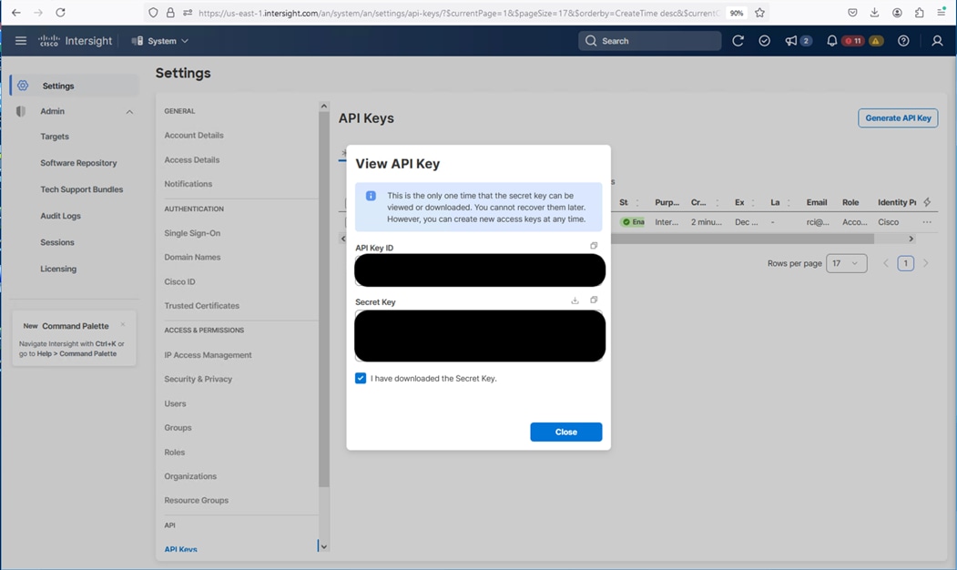
Step 3. Under Generate API Key, enter a Description and select API key for OpenAPI schema version 3. Select a date for the Expiration Time and click Generate.
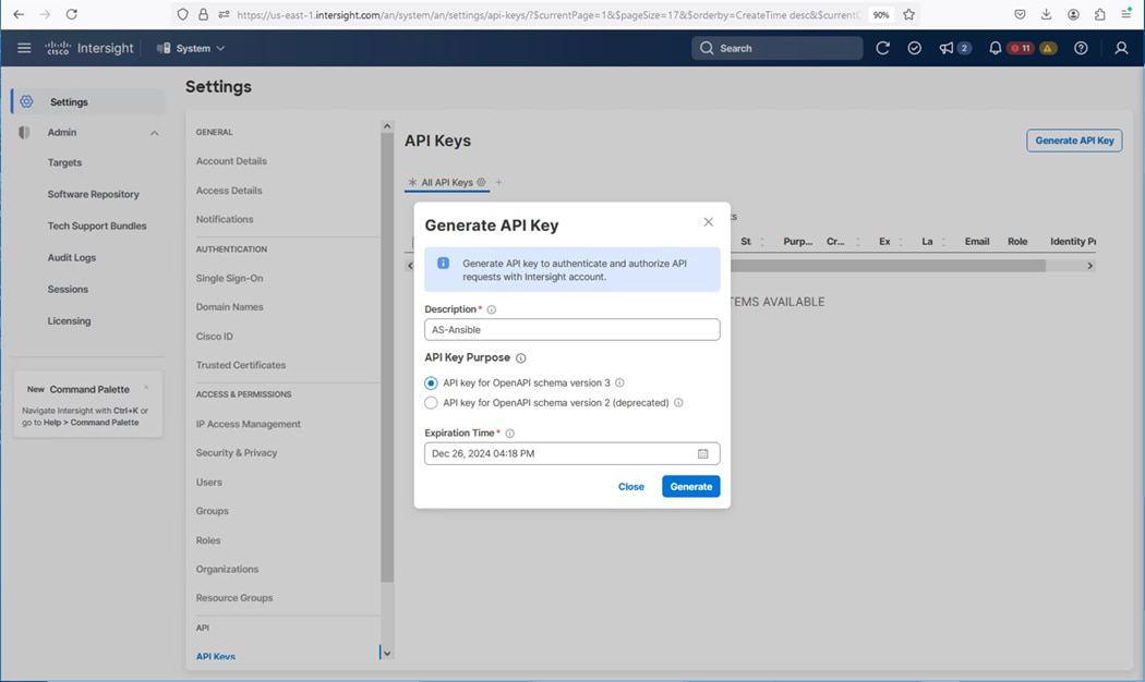
Step 4. Record the API Key ID, download the Secret Key, and click Close.
Step 5. With the API Key ID and the Secret Key properly recorded, they can be inserted under the group_vars folder in the github repo at https://github.com/ucs-compute-solutions/AdaptiveSolutions_IMM_FC_M7.
Step 6. Clone the repository to the intended Ansible control host, in the working directory:
The cloned repository will make available the following structure of files:
.
├── Setup_IMM_Pools.yml
├── Setup_IMM_Server_Policies.yml
├── Setup_IMM_Server_Profile_Templates.yml
├── group_vars
│ ├── all.yml
│ ├── secrets.sample
│ └── ucs.yml
└── roles
├── create_pools
│ ├── defaults
│ │ └── main.yml
│ └── tasks
│ ├── create_fc_ww_pools.yml
│ ├── create_ip_pools.yml
│ ├── create_mac_pools.yml
│ ├── create_uuid_pool.yml
│ └── main.yml
├── create_server_policies
│ ├── defaults
│ │ └── main.yml
│ └── tasks
│ ├── create_bios_policies.yml
│ ├── create_boot_order_policy.yml
│ ├── create_chassis_power_policy.yml
│ ├── create_chassis_thermal_policy.yml
│ ├── create_ethernet_adapter_policies.yml
│ ├── create_ethernet_network_control_policy.yml
│ ├── create_ethernet_network_group_policy.yml
│ ├── create_ethernet_qos_policy.yml
│ ├── create_fc_adapter_policy.yml
│ ├── create_fc_lan_connectivity_policy.yml
│ ├── create_fc_lan_connectivity_policy.yml.orig
│ ├── create_fc_network_policy.yml
│ ├── create_fc_nvme_initiator_adapter_policy.yml
│ ├── create_fc_qos_policy.yml
│ ├── create_imc_policy.yml
│ ├── create_ipmi_policy.yml
│ ├── create_kvm_policy.yml
│ ├── create_local_user_policy.yml
│ ├── create_san_connectivity_policy.yml
│ ├── create_vmedia_policy.yml
│ ├── gather_policy_info.yml
│ ├── gather_pool_info.yml
│ ├── main.yml
│ └── remove_local_user_policy
└── create_server_profile_template
├── defaults
│ └── main.yml
└── tasks
├── create_fc_server_profile_template.yml
├── gather_policy_info.yml
└── main.yml
Use of the repository is explained within the base README of the repository. The secrets.sample file under the group_vars directory is an example of how the API Key ID and the Secret Key can be inserted in the secrets.yml file that will need to be created.
Adjustments need to occur to the three group_vars files:
▪ all.yml – information relevant for referencing the base information of the configured UCS Domain.
▪ secrets.yml – the API Key ID and the Secret Key information referenced by all.yml
▪ ucs.yml – all information relevant to the intended Server Profiles created from the UCS Pools, Policies, and Server Profile Templates to be created.
Note: When adjusting the ucs.yml information, keep in mind the uniqueness requirement for the vNICs to avoid a conflict while creating the LAN Connectivity Policy.
Invocation is broken into three sections, separated by the following functions:
Step 7. Create the UCS Server Profile Pools (MAC,WWNN,WWPN,UUID,IP):
ansible-playbook ./Setup_IMM_Pools.yml
Step 8. Create the UCS Server Profile Policies:
ansible-playbook ./Setup_IMM_Server_Policies.yml
Step 9. Create the UCS Server Profile Template:
ansible-playbook ./Setup_IMM_Server_Profile_Templates.yml
Note: In each case, “--ask-vault-pass” should be added if the secrets.yml information has been encrypted with ansible-vault.
After invocation, a Server Profile Template should be available to create Server Profiles from:
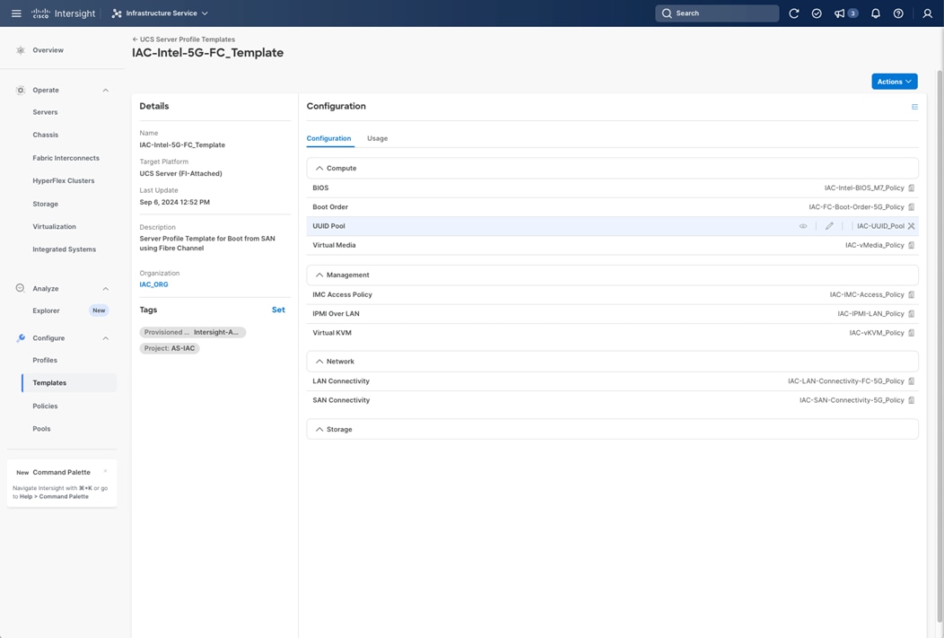
Hitachi VSP Provisioning with Ansible
Product user documentation and release notes for Storage Modules for Red Hat Ansible are available on Hitachi Vantara Documentation and identify the available storage modules, which can be used to configure the Hitachi VSP 5600 using Direct Connection with FC-SCSI. Check the website for the most current documentation, including system requirements and important updates that may have been made after the release of the product.
| Document |
Reference |
| User Guide |
https://docs.hitachivantara.com/v/u/en-us/adapters-and-drivers/3.0.x/mk-92adptr149 |
| Release Notes |
https://docs.hitachivantara.com/v/u/en-us/adapters-and-drivers/3.0.0/rn-92adptr150 |
| Installation Guide |
https://galaxy.ansible.com/ui/repo/published/hitachivantara/vspone_block/ |
| Installation File |
https://galaxy.ansible.com/ui/repo/published/hitachivantara/vspone_block/ |
For information on the system requirements and installation instructions using the direct connect option, see the “Hitachi Vantara VSP One Block Storage Modules for Red Hat Ansible 3.0.0 User Guide.”
The high-level deployment steps are as follows:
▪ VSP has been configured with storage pools.
▪ RHEL 9 VM was deployed on the vSphere Management Cluster.
▪ Created a dedicated user, “asuser”, on RHEL VM to install Hitachi Vantara VSP One Block Storage Modules for Red Hat Ansible 3.0.0 and to execute playbooks.
▪ Used PIP to deploy Ansible on RHEL VM: “pip install ansible”.
Hitachi Vantara VSP One Block Storage Modules for Red Hat Ansible 3.0.0 were installed on RHEL using the following command:
▪ “ansible-galaxy collection install hitachivantara.vspone_block”
▪ Reviewed the sample playbooks located in the following directory:
/home/asuser/.ansible/collections/ansible_collections/hitachivantara/vspone_block/playbooks/vsp_direct
▪ Completed connectivity details for the storage system can be found in the following file:
/home/asuser/.ansible/collections/ansible_collections/hitachivantara/vspone_block/playbooks/ansible_vault_vars/ansible_vault_storage_var.yml
The following are the sample playbooks that can optionally be used for the partial configuration of VSP FC-SCSI storage:
▪ Playbook - lun.yml can be used to:
▪ Create FC-SCSI boot volumes for servers.
▪ Create FC-SCSI Shared VMFS volumes for servers.
▪ Playbook - hostgroup.yml can be used to:
▪ Create host groups.
▪ Create volume mappings per host group.
Ansible Module “hv_lun” supports the creation, modification, or deletion of logical units (LUNs) on Hitachi VSP storage systems. It supports operations, such as creating a new LUN, updating an existing LUN, or deleting a LUN.
To view the documentation for a module, enter the following command on the Ansible control node:
“ansible-doc hitachivantara.vspone_block.vsp.<module_name>”
The sample playbook “lun.yml” uses the storage module “hv_lun” to manage LUNs for the Hitachi VSP storage configuration. The sample playbook includes the following tasks:
▪ Create a logical unit.
▪ Expand the size of a logical unit.
▪ Create a LUN using a parity group and auto-free LUN ID selection.
▪ Create a LUN with capacity saving and auto-free LUN ID selection.
▪ Delete a LUN.
The following tasks in the sample playbook “lun.yml” are extremely useful and can be used as a template:
▪ Task “Create a LUN” can be used to create boot volumes.
▪ Task “Create a LUN with capacity saving and auto free LUN ID selection” can be used to create FC-SCSI Shared VMFS volumes.
Within the sample playbook “lun.yml” file, select the appropriate tasks to allocate boot volumes to Cisco UCS Servers or to allocate FC-SCSI Shared VMFS volumes on the VSP. For information about the server boot volume or for the FC-SCSI Shared VMFS volume requirements and the associated dynamic pool, see: https://www.cisco.com/c/en/us/td/docs/unified_computing/ucs/UCS_CVDs/hitachi_adaptive_vmware_vsp.html
Note: Boot volumes and the FC-SCSI shared VMFS volumes have different attributes with associated tasks within the lun.yml sample playbook. Boot Volumes do not have Capacity Saving enabled and are provisioned from the Boot Pool, while VMFS Shared Volumes have Capacity Savings enabled and are provisioned from the Application Pool. The same task cannot be used to provision boot volumes and shared VMFS volumes.
Procedure 1. Provision Hitachi VSP with Ansible
Step 1. In the vsp_direct folder, copy the sample “lun.yml” file to a new playbook file using a naming convention appropriate to your user environment. A unique playbook should be configured for creating boot volumes, and a different unique playbook should be configured for creating a shared VMFS volume.
a. If creating boot volumes, create a new playbook by following the “Hitachi Vantara VSP One Block Storage Modules for Red Hat Ansible 3.0.0 User Guide” section for steps to “Create a Logical Unit”. Use the parameters for a direct connection. Fields in the specifications section of the documentation are marked as optional or required. Update the specifications section of your playbook based on your configuration requirements. Save the playbook.
b. If creating a Shared VMFS Volume, create a new playbook by following the “Hitachi Vantara VSP One Block Storage Modules for Red Hat Ansible 3.0.0 User Guide” section for steps to “Create a LUN with capacity savings and auto-free LUN ID selection” fields in the specifications section of the documentation are marked as optional or required. Update the specifications section of your playbook based on your configuration requirements. Delete any unused tasks in the new playbook
Table 3. Parameters – Connection information for a direct connection.
| Parameter |
Required |
Value/Description |
| connection type |
No |
Default: direct |
| Address |
Yes |
Storage Management address |
| username |
Yes |
Storage username |
| password |
Yes |
Storage password |
Table 4. Specifications for Creating a Logic Unit.
| Parameter |
Type |
Required |
Description |
| state |
String |
No |
Default: 'Present'. |
| pool_id |
Integer |
Yes |
ID of the pool where the LUN will be created. Options pool_id and parity_group_id are mutually exclusive. |
| parity_group_id |
Integer |
No |
ID of the parity_group where the LUN will be created. Options pool_id and parity_group_id are mutually exclusive. |
| size |
String |
Yes |
Size of the LUN. Can be specified in units, such as GB, TB, or MB (for example, '10GB', '5TB', '100MB', 200). |
| lun |
Integer |
No |
ID of the LUN; for new it will be assigned to this LUN if it's free. |
| name |
String |
No |
Name of the LUN (optional). |
| capacity_saving |
String |
No |
Whether capacity saving is compression, compression_deduplication or disabled. Default is disabled. |
Step 2. In the specifications table, there is a field named “lun”. In this context, the field name LUN refers to the LDEV ID.
Table 5. Specifications Creating a LUN with capacity savings and auto-free LUN ID selection.
| Parameter |
Type |
Required |
Description |
| state |
String |
No |
Default: 'Present' |
| pool_id |
Integer |
Yes |
ID of the pool where the LUN will be created. Options pool_id and parity_group_id are mutually exclusive. |
| size |
String |
Yes |
Size of the LUN. Can be specified in units such as GB, TB, or MB (for example, '10GB', '5TB', '100MB', 200). |
| name |
String |
No |
Name of the LUN (optional) |
| capacity_saving |
String |
Yes |
Whether capacity saving is compression, compression_deduplication or disabled. (Default is disabled) |
Sample Playbook – lun.yml
hosts: localhost
gather_facts: false
collections:
- hitachivantara.vspone_block.vsp
vars_files:
- ../ansible_vault_vars/ansible_vault_storage_var.yml
tasks:
- name: Create lun
hv_lun:
connection_info:
address: "{{ storage_address }}"
username: "{{ ansible_vault_storage_username }}"
password: "{{ ansible_vault_storage_secret }}"
storage_system_info:
serial: "{{ storage_serial }}"
state: present
spec:
lun: 345
pool_id: 15
size: 1GB
name: database_volume1
register: result
- debug:
var: result
- name: Expand size of lun
hv_lun:
connection_info:
address: "{{ storage_address }}"
username: "{{ ansible_vault_storage_username }}"
password: "{{ ansible_vault_storage_secret }}"
storage_system_info:
serial: "{{ storage_serial }}"
state: present
spec:
lun: 345
size: 8GB
register: result
- debug:
var: result
- name: Delete lun just created
hv_lun:
connection_info:
address: "{{ storage_address }}"
username: "{{ ansible_vault_storage_username }}"
password: "{{ ansible_vault_storage_secret }}"
storage_system_info:
serial: "{{ storage_serial }}"
state: absent
spec:
lun: 345
register: result
- debug:
var: result
- name: Create lun using parity group and auto free lun id selection
hv_lun:
connection_info:
address: "{{ storage_address }}"
username: "{{ ansible_vault_storage_username }}"
password: "{{ ansible_vault_storage_secret }}"
storage_system_info:
serial: "{{ storage_serial }}"
state: present
spec:
parity_group: '1-1'
size: 10GB
name: database_volume2
register: result
- debug:
var: result
- name: Create lun with capacity saving and auto free lun id selection
hv_lun:
connection_info:
address: "{{ storage_address }}"
username: "{{ ansible_vault_storage_username }}"
password: "{{ ansible_vault_storage_secret }}"
storage_system_info:
serial: "{{ storage_serial }}"
state: present
spec:
pool_id: 15
size: 1GB
capacity_saving: compression_deduplication
data_reduction_share: true
register: result
- debug:
var: result
- name: Delete lun
hv_lun:
connection_info:
address: "{{ storage_address }}"
username: "{{ ansible_vault_storage_username }}"
password: "{{ ansible_vault_storage_secret }}"
storage_system_info:
serial: "{{ storage_serial }}"
state: absent
spec:
lun: 345
register: result
- debug:
var: result
Step 3. On the Ansible control node, execute your playbook(s) using the following command when the ansible_vault_storage_var.yml file has not been encrypted.
[asuser@as-control vsp_direct]#ansible-playbook yourplaybook.yml
Step 4. Upon successful execution of the playbooks, verify the creation of the volumes with the correct parameters using the Hitachi Storage Navigator.
Procedure 2. Create host groups and mapping volumes (playbook hostgroup.yml)
Ansible Module “hv_hg” supports the creation, modification, or deletion of host groups, host modes, host mode options and the mapping/un-mapping of LUNs on Hitachi VSP storage systems.
Step 1. To view the documentation for a module, enter the following command on the Ansible control node:
ansible-doc hitachivantara.vspone_block.vsp.<module_name>
The sample playbook “hostgroup.yml” uses the storage module hv_hg to manage host groups for the Hitachi VSP storage configurations. The sample playbook includes the following tasks:
▪ Creating a Host Group.
▪ Updating Host Mode and Host Mode Options for the Host Group.
▪ Adding a WWN to the Host Group.
▪ Removing WWN from Host Group.
▪ Presenting LUNs to Host Group.
▪ Unpresenting LUNs from Host Group.
▪ Deleting a Host Group.
The following tasks in the playbooks are especially useful in configuring VSP Storage:
▪ Creating a Host Group.
▪ Volume Mapping per Host Group.
Procedure 3. Create a host group per server
Within the sample playbook “hostgroup.yml”, the “Create a Host Group” task can be updated and executed to create a host group with a specified name and World Wide Name (WWN), set the host mode, set the host mode options, set the Port ID, and auto assign a LUN ID to the LUN. Each task has a set of required or optional parameters. The “create a host group task” will only accept 1 FC port and one WWN should be configured per task.
Step 1. In the vsp_direct folder, copy the sample “hostgroup.yml” file to a new playbook using a naming convention appropriate to your user environment.
Step 2. Edit the new playbook by following the “Hitachi Vantara VSP One Block Storage Modules for Red Hat Ansible User Guide” section for steps to “Create a Host Group”. Use the parameters for a direct connection. Fields in the specifications section of the documentation are marked as optional or required. Update the specifications section of your new playbook based by referring to the following document for the required host group configuration for Cisco UCS servers: https://www.cisco.com/c/en/us/td/docs/unified_computing/ucs/UCS_CVDs/hitachi_adaptive_vmware_vsp.html
Step 3. The storage host group for each FC-SCSI port be configured initially without volume mapping. This will require removing the “luns” field from the task.
Table 6. Parameters – Connection information for a direct connection.
| Parameter |
Required |
Value/Description |
| connection type |
No |
Default: direct |
| Address |
Yes |
Storage Management address |
| username |
Yes |
Storage username |
| password |
Yes |
Storage password |
| Parameter |
Type |
Required |
Value/Description |
| state |
string |
Yes |
Default: 'present' |
| name |
string |
Yes |
Name of the host group. |
| port |
string |
Yes |
Fibre Channel port. |
| wwns |
list of string |
No |
List of host WWNs to add or remove. |
| luns |
list of string |
No |
LUNs to be mapped/unmapped with the host group. Supported format can be decimal or HEX. |
| host_mode |
string |
No |
Host mode of host group. Choices: LINUX, VMWARE, HP, OPEN_VMS, TRU64, SOLARIS, NETWARE, WINDOWS, HI_UX, AIX, VMWARE_EXTENSION, WIN-DOWS_EXTENSION, UVM, HP_XP, DYNIX |
| host_mode_options |
List of integers |
No |
List of host mode options of host group. Choices: Refer to the User’s Guide page 212 host mode options |
Sample playbook: hostgroup.yml
- name: Hostgroup Module
hosts: localhost
gather_facts: false
collections:
- hitachivantara.vspone_block.vsp
vars_files:
- ../ansible_vault_vars/ansible_vault_storage_var.yml
tasks:
- name: Create hostgroup
hv_hg:
connection_info:
address: "{{ storage_address }}"
username: "{{ ansible_vault_storage_username }}"
password: "{{ ansible_vault_storage_secret }}"
storage_system_info:
serial: "{{ storage_serial }}"
state: present
spec:
name: 'hostgroup-server1'
port: 'CL1-C'
host_mode: 'VMWARE_EXTENSION'
host_mode_options: [ 54, 63 ]
luns: [ 100, 200 ]
wwns: [ '9876543210ABCDE0', '9876543210ABCDE1' ]
register: result
- debug:
var: result
- name: Update host mode and host mode options
hv_hg:
connection_info:
address: "{{ storage_address }}"
username: "{{ ansible_vault_storage_username }}"
password: "{{ ansible_vault_storage_secret }}"
storage_system_info:
serial: "{{ storage_serial }}"
state: present
spec:
state: set_host_mode_and_hmo
name: 'hostgroup-server1'
port: 'CL1-C'
host_mode: 'LINUX'
host_mode_options: [ 13 ]
register: result
- debug:
var: result
- name: Remove host mode options
hv_hg:
connection_info:
address: "{{ storage_address }}"
username: "{{ ansible_vault_storage_username }}"
password: "{{ ansible_vault_storage_secret }}"
storage_system_info:
serial: "{{ storage_serial }}"
state: present
spec:
state: absent
name: 'hostgroup-server1'
port: 'CL1-C'
host_mode_options: [ 13 ]
register: result
- debug:
var: result
- name: Add wwns to hostgroup
hv_hg:
connection_info:
address: "{{ storage_address }}"
username: "{{ ansible_vault_storage_username }}"
password: "{{ ansible_vault_storage_secret }}"
storage_system_info:
serial: "{{ storage_serial }}"
state: present
spec:
state: add_wwn
name: 'hostgroup-server1'
port: 'CL1-C'
wwns: [ '9876543210ABCDED', '9876543210ABCDEE' ]
register: result
- debug:
var: result
- name: Remove wwns from hostgroup
hv_hg:
connection_info:
address: "{{ storage_address }}"
username: "{{ ansible_vault_storage_username }}"
password: "{{ ansible_vault_storage_secret }}"
storage_system_info:
serial: "{{ storage_serial }}"
state: present
spec:
state: remove_wwn
name: 'hostgroup-server1'
port: 'CL1-C'
wwns: [ '9876543210ABCDED', '9876543210ABCDEE' ]
register: result
- debug:
var: result
- name: Present luns to hostgroup
hv_hg:
connection_info:
address: "{{ storage_address }}"
username: "{{ ansible_vault_storage_username }}"
password: "{{ ansible_vault_storage_secret }}"
storage_system_info:
serial: "{{ storage_serial }}"
state: present
spec:
state: 'present_lun'
name: 'hostgroup-server1'
port: 'CL1-C'
luns: [ 300, 400 ]
register: result
- debug:
var: result
- name: Unpresent luns from hostgroup
hv_hg:
connection_info:
address: "{{ storage_address }}"
username: "{{ ansible_vault_storage_username }}"
password: "{{ ansible_vault_storage_secret }}"
storage_system_info:
serial: "{{ storage_serial }}"
state: present
spec:
state: 'unpresent_lun'
name: 'hostgroup-server1'
port: 'CL1-C'
luns: [ 300, 400 ]
register: result
- debug:
var: result
- name: Delete hostgroup
hv_hg:
connection_info:
address: "{{ storage_address }}"
username: "{{ ansible_vault_storage_username }}"
password: "{{ ansible_vault_storage_secret }}"
storage_system_info:
serial: "{{ storage_serial }}"
state: absent
spec:
name: 'hostgroup-server1'
port: 'CL1-C'
should_delete_all_luns: true
register: result
- debug:
var: result
Step 4. On the Ansible control node, execute the playbook using the following command:
[asuser@as-control vsp_direct]# ansible-playbook yourplaybook.yml
Step 5. Upon successful execution of the playbook, verify creation of the host group with the correct configuration parameters using the Hitachi Storage Navigator connected to the VSP.
Step 6. Repeat steps 1 – 5 for each configured VSP FC-SCSI port.
Procedure 4. Volume Mapping per host group
Within the sample playbook “hostgroup.yml”, the “present luns to hostgroup” task can be updated and executed to map a single volume or multiple volumes to a host group. The VSP server configuration includes both boot volumes and Shared VMFS volumes with a specific LUN ID order, where Boot LUNs must have LUN ID 0 assigned.
Note: The new playbook will have to be updated and executed twice. During the first iteration, the new playbook should only reference the boot volume LDEV ID. During the second iteration, the playbook should only reference the FC-SCSI shared VMFS volume LDEV ID. This process will ensure assigning a LUN ID of 0 to the boot volume.
Step 1. In the vsp_direct folder, copy the sample “hostgroup.yml” file to a new playbook using a naming convention appropriate to your user environment. In the new playbook, remove any unused tasks.
Step 2. Edit the new playbook by following the “Hitachi Vantara VSP One Block Storage Modules for Red Hat Ansible User Guide” section for “Present LUNs to a Host Group”. Use the parameters for a direct connection. Fields in the specifications section of the documentation are marked as optional or required and must be updated for your environment.
Step 3. In the Sample Playbook under “name: Present luns to hostgroup” there is a field name luns. To ensure that the boot volume is assigned a LUN IDof 0. The first execution of this playbook will only map the boot volume. During the second execution of this playbook, only map the FC-SCSI shared VMFS volume to the host group.
Step 4. Update the specifications of your playbook based by referring to the following document for the required volume mapping: https://www.cisco.com/c/en/us/td/docs/unified_computing/ucs/UCS_CVDs/hitachi_adaptive_vmware_vsp.html
Table 8. Parameters – Connection information for a direct connection.
| Parameter |
Required |
Value/Description |
| connection_type |
No |
Default: direct |
| Address |
Yes |
Storage Management address |
| username |
Yes |
Storage username |
| password |
Yes |
Storage password |
| Parameter |
Type |
Required |
Description |
| state |
string |
Yes |
Sub-task operation. Choices: [“present_lun”] |
| name |
string |
Yes |
Name of the host group. |
| port |
string |
Yes |
Fibre Channel port. |
| luns |
list of string |
Yes |
LUNs to be mapped orunmapped with the host group. Supported format can be decimal or HEX. |
Note: In the Specifications table, there is a field name luns. In this context, the field name lun refers to the LDEVID.
Sample playbook hostgroup.yml
- name: Hostgroup Module
hosts: localhost
gather_facts: false
collections:
- hitachivantara.vspone_block.vsp
vars_files:
- ../ansible_vault_vars/ansible_vault_storage_var.yml
tasks:
- name: Create hostgroup
hv_hg:
connection_info:
address: "{{ storage_address }}"
username: "{{ ansible_vault_storage_username }}"
password: "{{ ansible_vault_storage_secret }}"
storage_system_info:
serial: "{{ storage_serial }}"
state: present
spec:
name: 'hostgroup-server1'
port: 'CL1-C'
host_mode: 'VMWARE_EXTENSION'
host_mode_options: [ 54, 63 ]
luns: [ 100, 200 ]
wwns: [ '9876543210ABCDE0', '9876543210ABCDE1' ]
register: result
- debug:
var: result
- name: Update host mode and host mode options
hv_hg:
connection_info:
address: "{{ storage_address }}"
username: "{{ ansible_vault_storage_username }}"
password: "{{ ansible_vault_storage_secret }}"
storage_system_info:
serial: "{{ storage_serial }}"
state: present
spec:
state: set_host_mode_and_hmo
name: 'hostgroup-server1'
port: 'CL1-C'
host_mode: 'LINUX'
host_mode_options: [ 13 ]
register: result
- debug:
var: result
- name: Remove host mode options
hv_hg:
connection_info:
address: "{{ storage_address }}"
username: "{{ ansible_vault_storage_username }}"
password: "{{ ansible_vault_storage_secret }}"
storage_system_info:
serial: "{{ storage_serial }}"
state: present
spec:
state: absent
name: 'hostgroup-server1'
port: 'CL1-C'
host_mode_options: [ 13 ]
register: result
- debug:
var: result
- name: Add wwns to hostgroup
hv_hg:
connection_info:
address: "{{ storage_address }}"
username: "{{ ansible_vault_storage_username }}"
password: "{{ ansible_vault_storage_secret }}"
storage_system_info:
serial: "{{ storage_serial }}"
state: present
spec:
state: add_wwn
name: 'hostgroup-server1'
port: 'CL1-C'
wwns: [ '9876543210ABCDED', '9876543210ABCDEE' ]
register: result
- debug:
var: result
- name: Remove wwns from hostgroup
hv_hg:
connection_info:
address: "{{ storage_address }}"
username: "{{ ansible_vault_storage_username }}"
password: "{{ ansible_vault_storage_secret }}"
storage_system_info:
serial: "{{ storage_serial }}"
state: present
spec:
state: remove_wwn
name: 'hostgroup-server1'
port: 'CL1-C'
wwns: [ '9876543210ABCDED', '9876543210ABCDEE' ]
register: result
- debug:
var: result
- name: Present luns to hostgroup
hv_hg:
connection_info:
address: "{{ storage_address }}"
username: "{{ ansible_vault_storage_username }}"
password: "{{ ansible_vault_storage_secret }}"
storage_system_info:
serial: "{{ storage_serial }}"
state: present
spec:
state: 'present_lun'
name: 'hostgroup-server1'
port: 'CL1-C'
luns: [ 300, 400 ]
register: result
- debug:
var: result
- name: Unpresent luns from hostgroup
hv_hg:
connection_info:
address: "{{ storage_address }}"
username: "{{ ansible_vault_storage_username }}"
password: "{{ ansible_vault_storage_secret }}"
storage_system_info:
serial: "{{ storage_serial }}"
state: present
spec:
state: 'unpresent_lun'
name: 'hostgroup-server1'
port: 'CL1-C'
luns: [ 300, 400 ]
register: result
- debug:
var: result
- name: Delete hostgroup
hv_hg:
connection_info:
address: "{{ storage_address }}"
username: "{{ ansible_vault_storage_username }}"
password: "{{ ansible_vault_storage_secret }}"
storage_system_info:
serial: "{{ storage_serial }}"
state: absent
spec:
name: 'hostgroup-server1'
port: 'CL1-C'
should_delete_all_luns: true
register: result
- debug:
var: result
Step 5. On the Ansible control node, execute the playbook using the following command:
[asuser@as-control vsp_direct]# ansible-playbook yourplaybook.yml
Step 6. Upon successful execution of the playbook, verify the correct volume mapping to the host group using the Hitachi Storage Navigator connected to the VSP.
Step 7. Repeat steps 1-5 to map the FC-SCSI shared VMFS volume to the host group.
Hitachi Storage Plug-in for VMware vCenter
Product user documentation and release notes for Hitachi Storage Plug-in for VMware vCenter are available on Hitachi Vantara Documentation and provide deployment and usage information. Check the website for the most current documentation, including system requirements and important updates that may have been made after the release of the product.
The Hitachi Storage Plug-in for VMware vCenter User’s Guide can be found here: https://docs.hitachivantara.com/v/u/en-us/adapters-and-drivers/4.10.x/mk-92adptr047
The document includes:
▪ Hardware, software, and storage system requirements.
▪ Key restrictions and considerations.
▪ Installation, upgrade, and management process.
▪ Setting the LUN ID range for provisioning LUNs.
Note: vVols Datastores or volumes cannot be allocated with the Hitachi Storage Plug-in. In addition, VMFS Datastores or volumes cannot be allocated with the Hitachi Storage Plug-in that use FC-NVMe.
For more information on installation information, see the Hitachi Storage Plug-in for VMware vCenter User’s Guide.
The following sections document how to register the Hitachi VSP to Ops Center Configuration Manager and how to use the Storage Plug-in for VMware vCenter.
Procedure 1. Register Hitachi Virtual Storage Platform to Ops Center Configuration Manager Server
Step 1. Open the API client.
Step 2. Enter the base URL for the deployed Hitachi Ops Center API Configuration Manager IP address. For example, https://[Ops_Center_IP]:23450/ConfigurationManager/v1/objects/storages.
Step 3. Click the Authorization tab.
a. Select Basic from the Select authorization menu.
b. Enter the Username and Password for the VSP storage system.
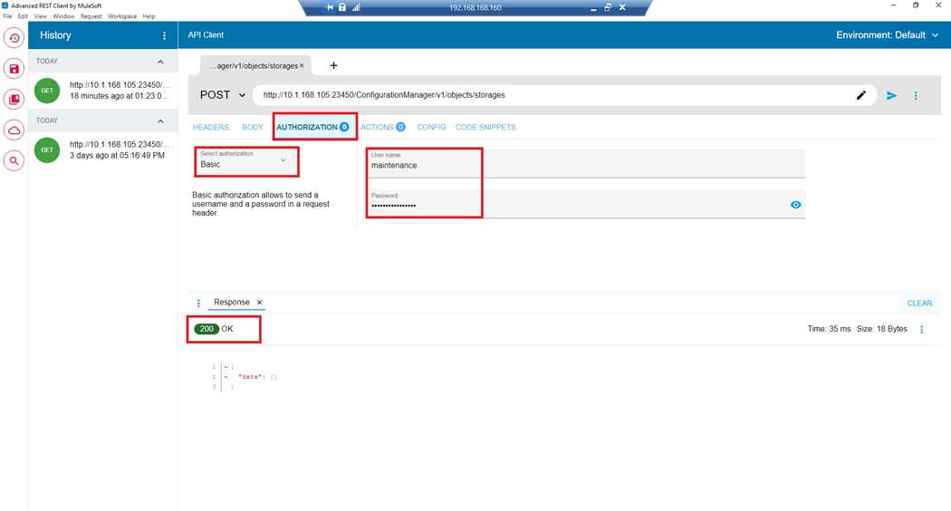
Step 4. Click the Body tab. Enter the VSP storage SVP IP, Serial Number, and Model as indicated in the following examples in JSON format.
Note: If the VSP is a midrange storage system, it will be CTL1 and CTL2 IP instead of SVP IP.
The following example uses a VSP 5600:
{
“svpIp”: “192.168.1.10”,
“serialNumber”: 60749,
“model”: “VSP 5600”
}
Step 5. Under the HEADERS tab verify the following:
a. Accept: application/json
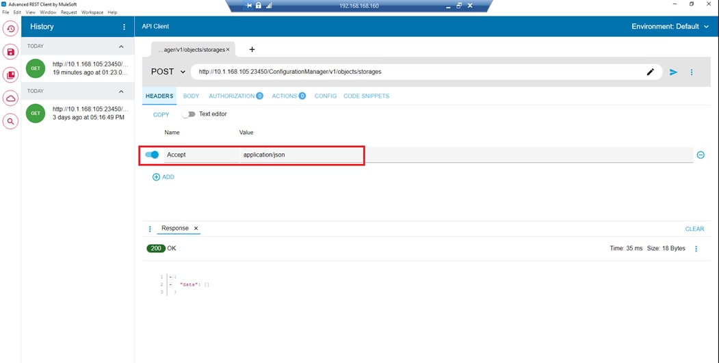
Step 6. Verify that the REST call is set to POST. Click Submit.
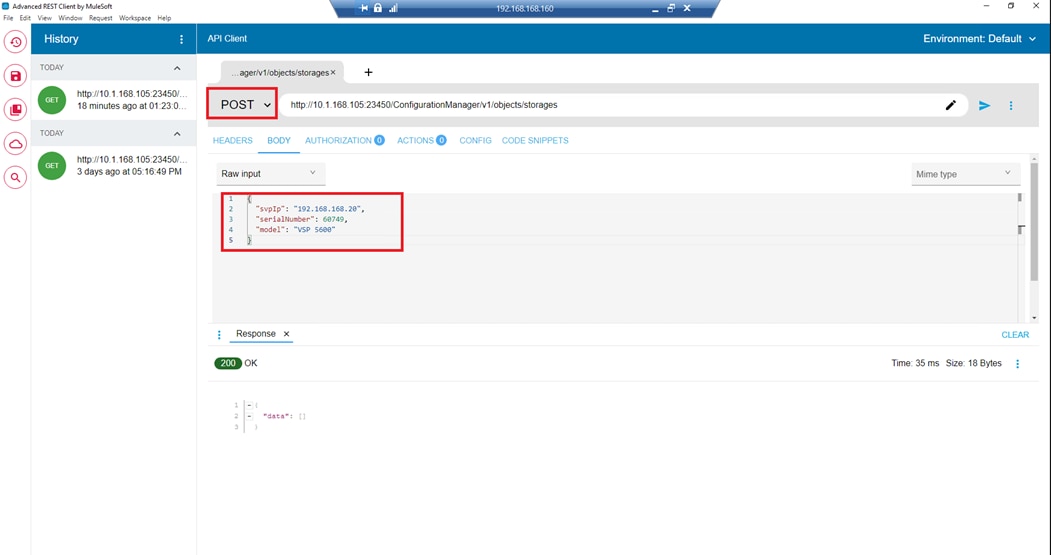
Step 7. After successful registration, a response header is displayed as 200 OK.
Step 8. To confirm onboarding, the API parameter can be updated to the GET method to retrieve storage system information and can be verified with 200 OK status.
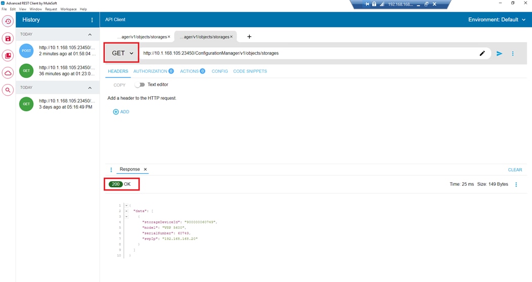
Hitachi Storage Plug-in for VMware vCenter
The following sections document the procedures to use the Storage Plug-in for VMware vCenter and include the following topics:
▪ Accessing the Storage Plug-in for VMware vCenter
▪ Onboarding a Hitachi VSP
▪ Refreshing the storage system
▪ Creating a VMFS datastores
▪ Expanding a datastore
▪ Deleting a datastore
▪ Viewing native storage volume information
Procedure 1. Access the Storage Plug-in for VMware vCenter
Step 1. Log in to the vSphere Client from a browser.
Step 2. In the vSphere Client, click Menu.
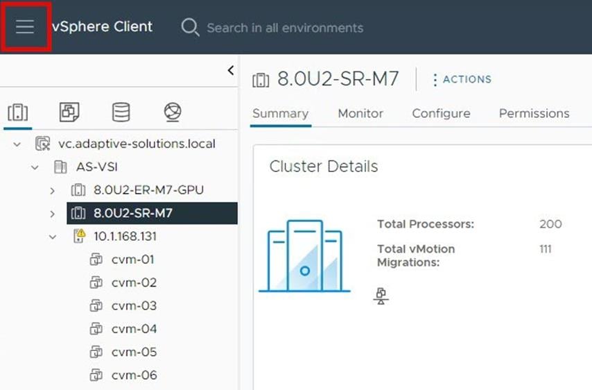
Step 3. Select Hitachi Storage Plug-in.
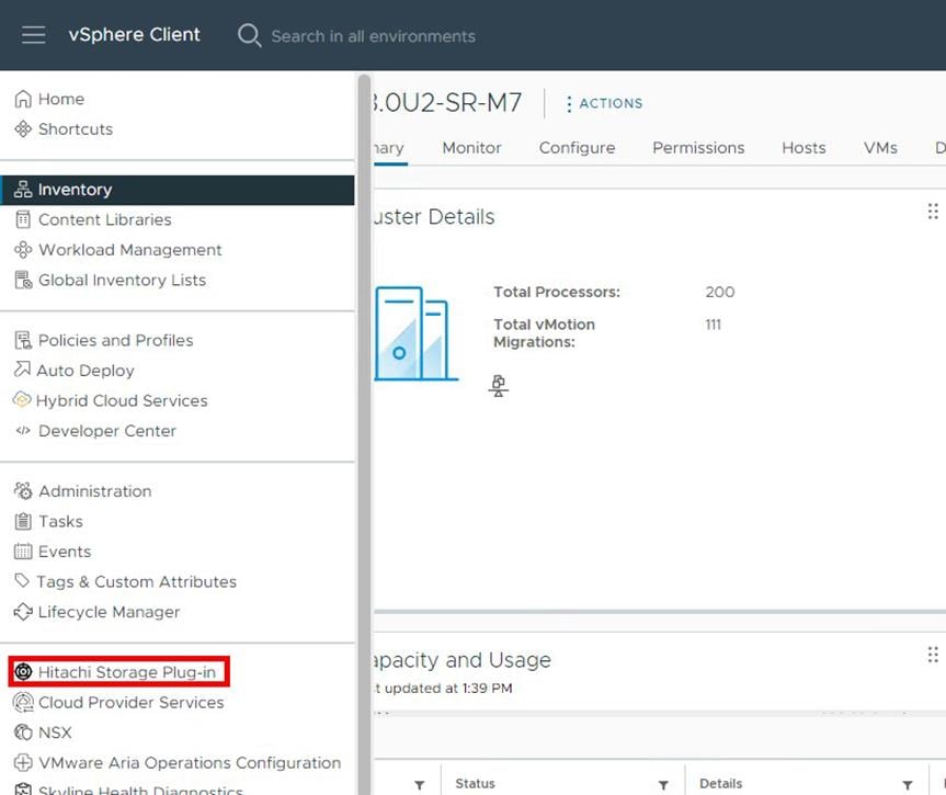
Procedure 2. Onboard a Hitachi VSP
Step 1. Run the Add Storage Systems operation to register storage systems to be monitored by Hitachi Storage Plug-in. Select the Add Storage Systems label.
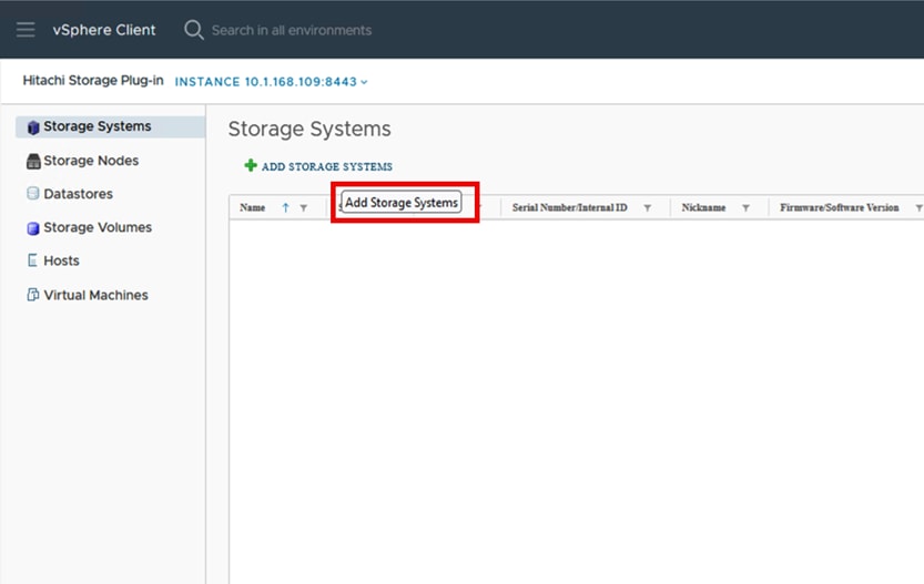
Step 2. On the Type tab select VSP Storage System and click NEXT.
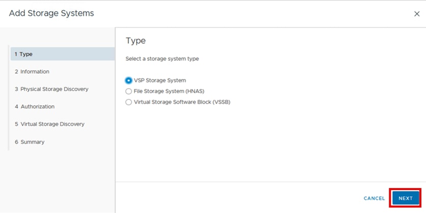
Step 3. On the Information tab enter the IP Address, Port Number, and select Use SSL, and click NEXT.
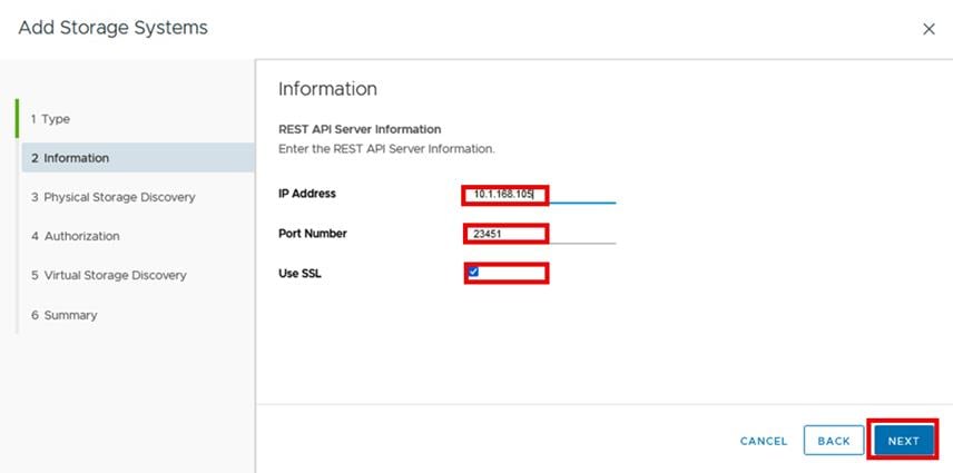
Step 4. On the Physical Storage Discovery tab, verify the system model and serial number. Select the VSP 5600 and click NEXT.
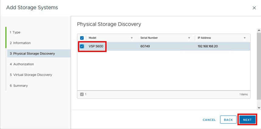
Step 5. In the Authorization tab, enter the User ID and Password, and click NEXT.
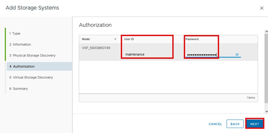
Step 6. On the Virtual Storage Discovery tab, select the entry for VSP5200, 5600, and click NEXT.
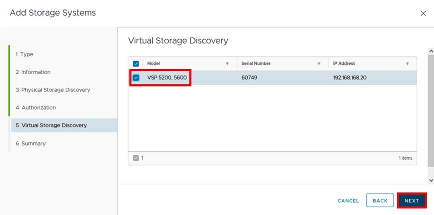
Step 7. On the Virtual Storage Summary tab click FINISH.
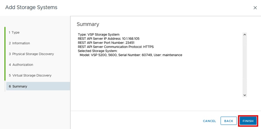
Procedure 3. Refresh the Storage System
Refreshing storage systems updates information about the selected array.
Step 1. In the Hitachi Storage Plug-in pane, click Storage Systems.
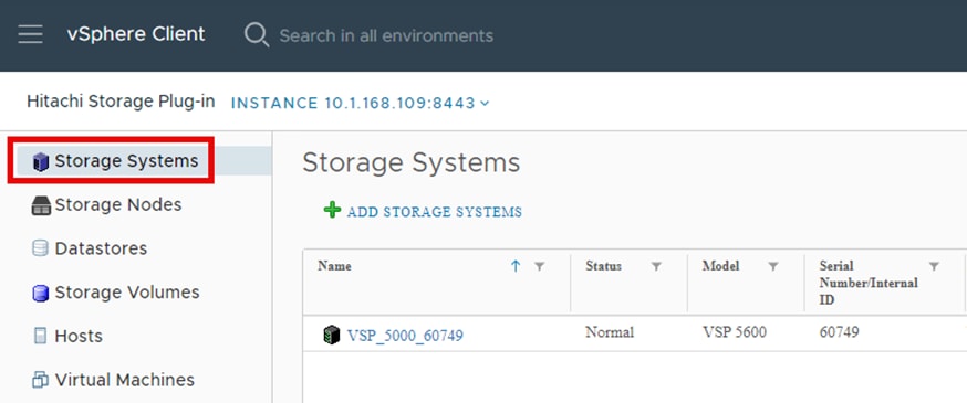
Step 2. Select the storage system under the Name column.
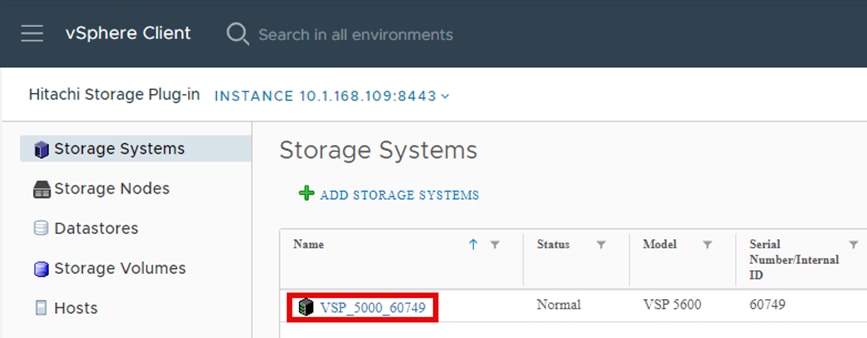
Step 3. From the Actions drop-down list, select Refresh Storage Systems.
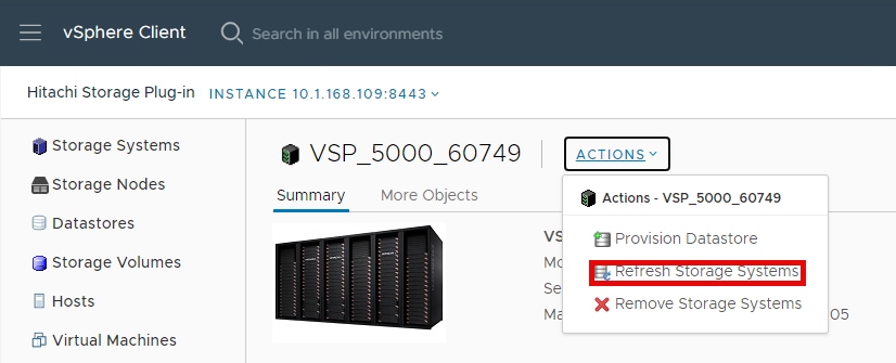
Step 4. To confirm refreshing the selected storage systems, select YES.
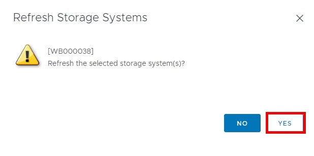
The following status message displays temporarily and disappears when the Refresh Storage Systems task has been completed.
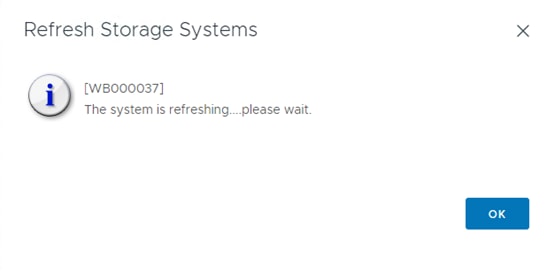
Procedure 4. Create a VMFS Datastore
Running Provision Datastore enables you to create LDEVs or volumes for storage systems registered in Storage Plug-in for VMware vCenter. You can use the created LDEV or volumes as VMFS datastores, or RDMs. Host groups must have been created with the associated World Wide Name (WWN) of the vHBA registered. Otherwise, the host group will not appear on the selection screen.
▪ You can run Provision Datastore from the following screens:
▪ Storage Volumes list screen (Provision Datastore icon)
▪ Datastores list screen (Provision Datastore icon)
▪ Action menu on the Storage Systems Summary screen or another screen
Prerequisites
▪ Verify that all relevant ESXi hosts are connected to the storage system by Fibre Channel.
▪ Select a storage system to create an LDEV or volume on.
▪ Ensure that the DP pool, which creates the LDEV, or volume used in the VMFS datastore, exists.
▪ Verify the Host group of the storage system in which the WWN of the storage adapter (ESXi HBA) is set. Make sure that the storage system information and vSphere environment information are current. If the information is outdated, run Refresh Storage Systems.
Step 1. In the Hitachi Storage Plug-in pane, click Storage Volumes.
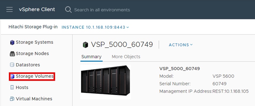
Step 2. Click the PROVISION DATASTORE to start the provision datastore process.
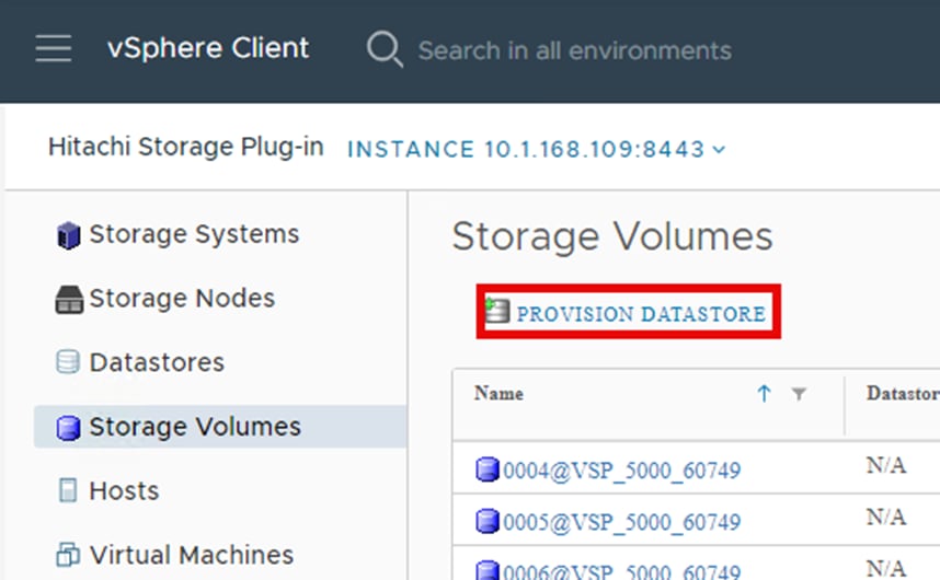
Step 3. On the Type screen, select VMFS Datastore, and then click NEXT.
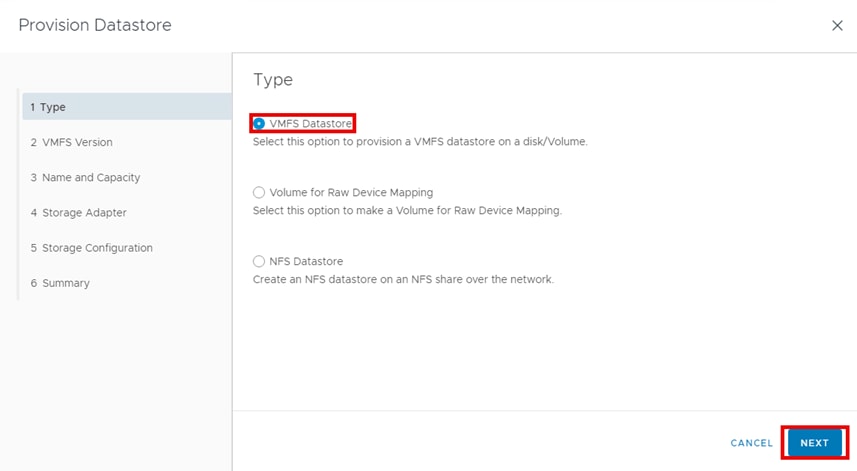
Step 4. On the VMFS Version screen, select VMFS6, and then click NEXT.
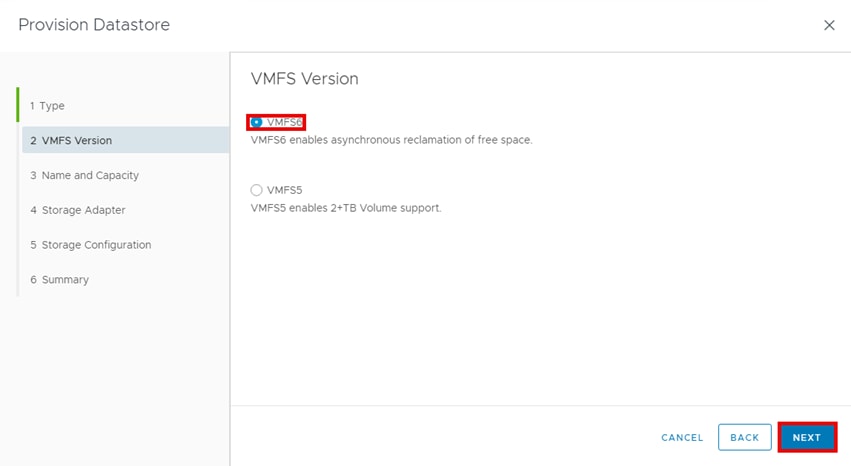
Step 5. Select Single Datastore Creation and enter a name and set the Datastore Capacity based on your requirements, and then click NEXT.
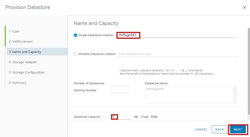
Step 6. Expand the high-level vCenter, select the cluster, and select the ESXi Hosts/Devices that will have access to the datastore being provisioned, then click NEXT.
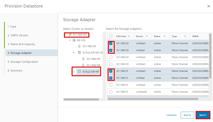
Step 7. Enter the Storage Configuration by completing the fields and click NEXT.
▪ Storage System: Select the menu and select the appropriate VSP.
▪ Pool/Raid Group: Select the menu and select the Pool ID based on the type of datastore being deployed. Pool ID 2 will be used for this example and is named UCS_Application_Pool.
▪ Setting the Capacity Saving: Select the down arrow. Deduplication and Compression will be used in this example.
▪ LUN ID: (optional): Enter 60 for this example.
Note: This value is the LUN ID and differs from the VSP LDEV ID.
▪ Host Group/Target: Select the checkbox next to Host Group/Target
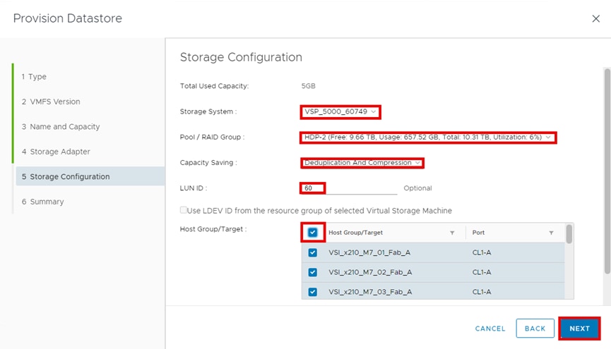
Step 8. Review the Summary and click FINISH.
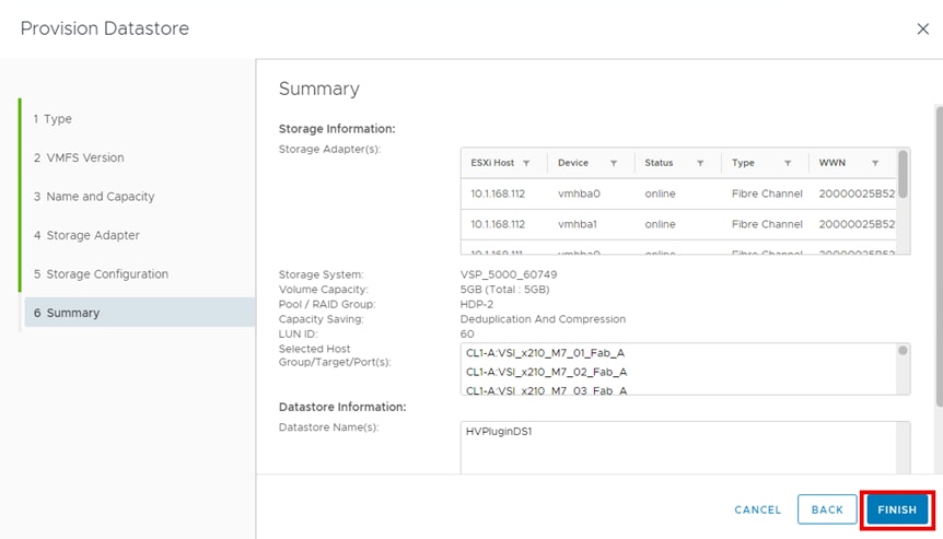
Step 9. After the task is completed, select Datastores and verify that the new datastore “HVPluginDS1” has been created.
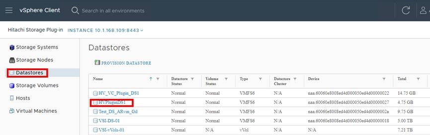
Step 10. On the vCenter select Menu, and then select Inventory.
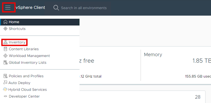
Step 11. Select Storage and verify that the new Datastore has been created and available on the cluster.
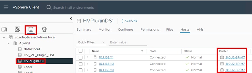
Procedure 5. Expand a Datastore
Using the Expand Datastore feature, you can expand the capacity of an existing datastore.
Note: You cannot use this function for vVols datastores.
Step 1. In the vSphere Hitachi Storage Plug-in pane, click Datastores.
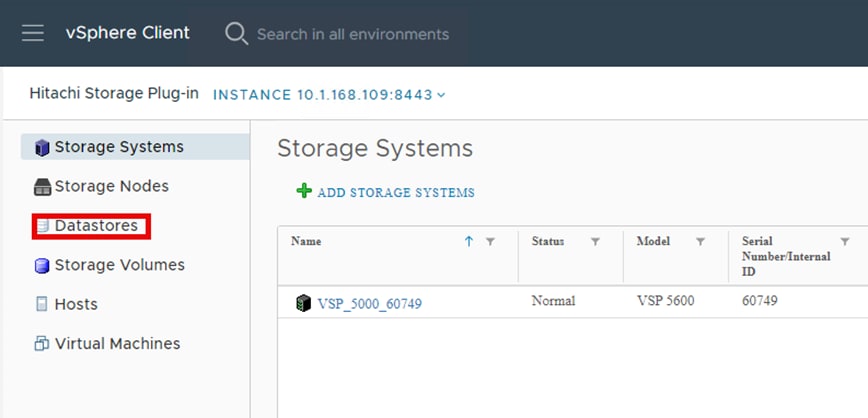
Step 2. In the vSphere Hitachi Storage Plug-in pane, click Datastores, select the datastore you want to expand, and click Expand Datastore.
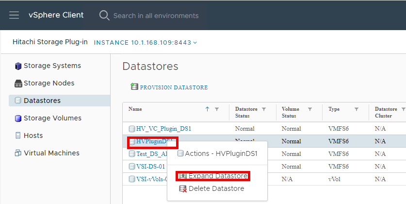
Step 3. In Storage Configuration, enter the Additional Capacity value by which you want to expand the volume. This value will be added to the existing size. Click NEXT.
Note: If you specify 0, the volume is not expanded, but the datastore is expanded to the maximum capacity of the volume if the datastore capacity does not already match the maximum capacity of the volume. If the expansion fails, the volume's status becomes ExpansionFailed. If you perform expansion again for the same volume, the value you entered for Storage Configuration is ignored, and the volume is expanded based on the value that was set when expansion failed.
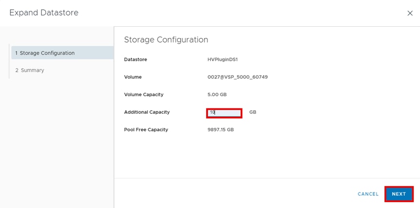
Step 4. Review the Summary page and click FINISH.
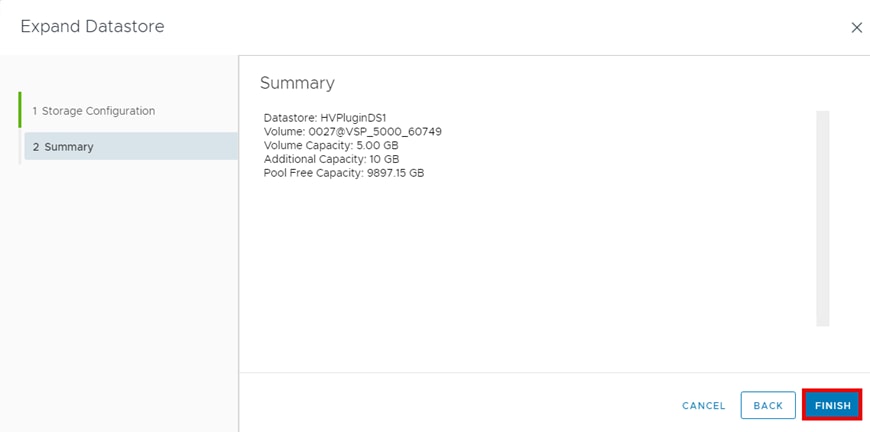
Step 5. In the vSphere Hitachi Storage Plug-in pane, click Datastores. Refresh the window and review the new size of the datastore.
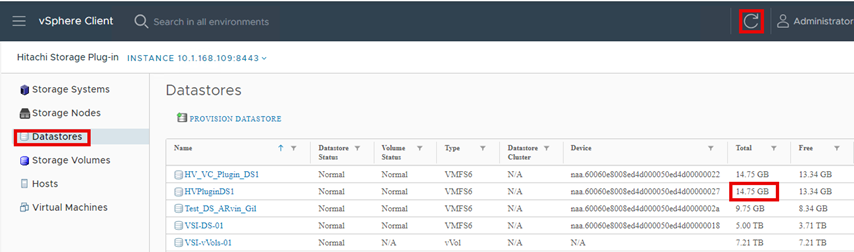
Procedure 6. Delete a Datastore
Running Delete Datastore lets you delete VMFS datastores and the backend LDEV on the Hitachi VSP. vVols and the following datastores cannot be deleted by using Delete Datastore function:
▪ Datastores with a virtual machine or virtual machine template.
▪ Datastores with multiple LUs/volumes.
▪ Datastores with pair-configured LUs/volumes.
▪ Datastores with LUs/volumes used in Raw Device Mapping (RDM).
Note: Even after datastores/LUs/volumes that were created by selecting Deduplication and Compression have been deleted from the Hitachi Storage Plug-in screen, it might take some time before the LUs/volumes in the storage system are completely deleted. After the deletion, it might take time before free space in the pool increases.
Step 1. In the vSphere Hitachi Storage Plug-in window, click Datastores.

Step 2. In the vSphere Hitachi Storage Plug-in pane, select the Datastore you want to delete and click Delete Datastore.
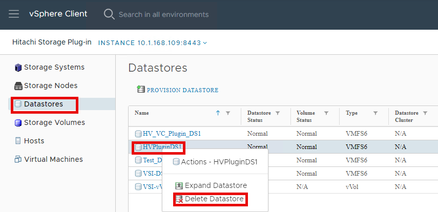
Step 3. From the Delete Datastore prompt, click YES to proceed with the deletion.
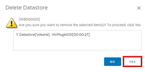
Step 4. On the Hitachi Storage Plug-in pane, select Datastores, click refresh several times until the deleted Datastore is no longer available. This deletion may take several minutes to complete.
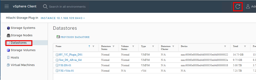
Procedure 7. View VSP Native Storage Volume Information
Selecting the vSphere storage icon and highlighting a datastore will present a Summary View that displays the Hitachi Storage Plug-in. This plug-in provides a deep, native view into configured storage volumes, including the storage volumeIDEV ID, Free Capacity Information, Total Capacity Information, Configured Capacity Savings options, the VSP Pool ID, and Status.
Step 1. In vSphere Client, click the Storage icon and highlight a datastore. Under the datastore Summary tab, under the Hitachi Storage Plug-in pane, click the Storage Volume name to view detailed information.
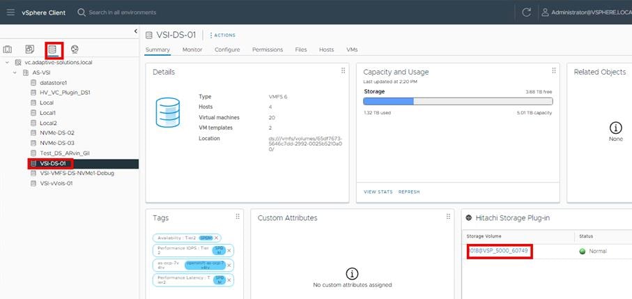
From the Storage Plug-in, detailed information will be displayed providing the volume status, capacity, volume path, and pool information.
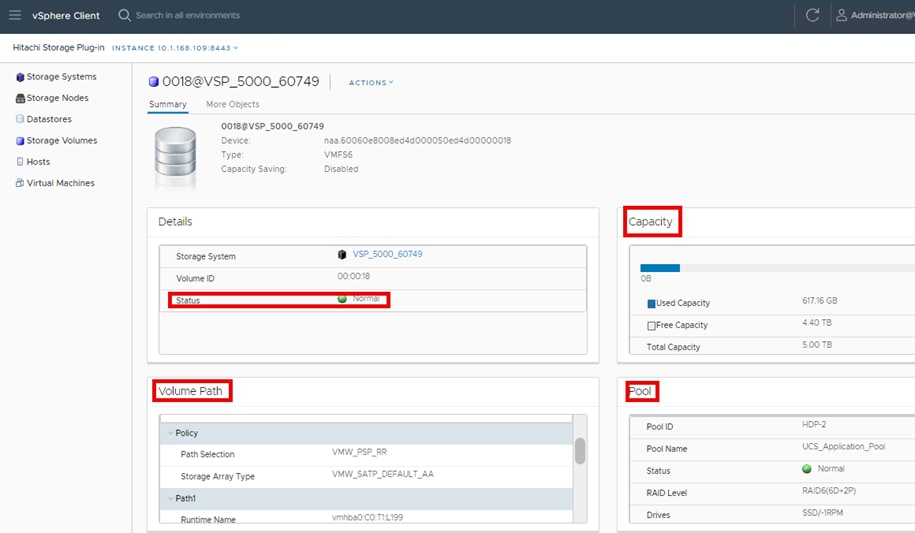
OCP Persistent Storage and Networking Verification
Using Helm, the Wordpress database application was deployed in a stateful container provisioned with a PVC and was used to demonstrate OCP container network functionality along with persistent data storage. Helm allows you to install complex container-based applications easily with the ability to customize the deployment to your needs.
Procedure 1. Install and configure Helm utilities
Step 1. Log into the Linux VM hosting the OCP CLI client.
Step 2. Install the Helm binary by following the Helm documentation for your distribution. For the Helm documentation, go to: https://helm.sh/docs/intro/install/
Step 3. Add the Bitnami repository to your Helm configuration by running the following command:
helm repo add bitnami https://charts.bitnami.com/bitnami
Step 4. Search for the MySQL Helm chart by running the following command:
helm search repo wordpress
Step 5. Verify that the Helm binary is installed properly and the bitnami repository has been added with a MySQL Helm chart available for use by running the following command:
helm search repo wordpress
[as-control@as-control ~]$ helm search repo wordpress
WARNING: Kubernetes configuration file is group-readable. This is insecure. Location: /home/as-control/auth/kubeconfig
NAME CHART VERSION APP VERSION DESCRIPTION
bitnami/wordpress 23.1.14 6.6.2 WordPress is the world's most popular blogging ...
bitnami/wordpress-intel 2.1.31 6.1.1 DEPRECATED WordPress for Intel is the most popu...
[as-control@as-control ~]$
Procedure 2. Customize and deploy Wordpress Helm chart with Persistent Storage
You can customize a Helm chart deployment by downloading the chart values to a YAML file and using that file during Helm chart installation. You can also specify the custom values for a deployment on the command line or in a script.
Step 1. Create a project with the following command:
oc new-project demoapps1
[as-control@as-control ~]$ oc new-project demoapps1
Now using project "demoapps1" on server "https://api.as-ocp.adaptive-solutions.local:6443".
Step 2. Set the appropriate SecurityContext for the project and pods with the following commands:
oc adm policy add-scc-to-user privileged system:serviceaccount:demoapps1:wordpress-mariadb
oc adm policy add-scc-to-user privileged system:serviceaccount:demoapps1:default
[as-control@as-control ~]$ oc adm policy add-scc-to-user privileged system:serviceaccount:demoapps1:wordpress-mariadb
clusterrole.rbac.authorization.k8s.io/system:openshift:scc:privileged added: "wordpress-mariadb"
[as-control@as-control ~]$ oc adm policy add-scc-to-user privileged system:serviceaccount:demoapps1:default
clusterrole.rbac.authorization.k8s.io/system:openshift:scc:privileged added: "default"
Step 3. Deploy Wordpress Helm chart using the following command and press Enter:
helm install -n demoapps1 wordpress \
--set wordpressUsername=admin \
--set wordpressPassword=Hitachi123 \
--set replicaCount=1 \
--set persistence.storageClass=csi-sc \
--set persistence.size=3Gi \
--set mariadb.primary.persistence.storageClass=csi-sc \
--set mariadb.primary.persistence.size=5Gi \
--set podSecurityContext.enabled=false \
--set containerSecurityContext.enabled=false \
--set primary.podSecurityContext.enabled=false \
--set primary.containerSecurityContext.enabled=false \
bitnami/wordpress”
[as-control@as-control ~]$ helm install -n demoapps1 wordpress \
--set wordpressUsername=admin \
--set wordpressPassword=Hitachi123 \
--set replicaCount=1 \
--set persistence.storageClass=csi-sc \
--set persistence.size=3Gi \
--set mariadb.primary.persistence.storageClass=csi-sc \
--set mariadb.primary.persistence.size=5Gi \
--set podSecurityContext.enabled=false \
--set containerSecurityContext.enabled=false \
--set primary.podSecurityContext.enabled=false \
--set primary.containerSecurityContext.enabled=false \
bitnami/wordpress
WARNING: Kubernetes configuration file is group-readable. This is insecure. Location: /home/as-control/auth/kubeconfig
NAME: wordpress
LAST DEPLOYED: Tue Sep 17 14:51:56 2024
NAMESPACE: demoapps1
STATUS: deployed
REVISION: 1
TEST SUITE: None
NOTES:
CHART NAME: wordpress
CHART VERSION: 23.1.14
APP VERSION: 6.6.2
** Please be patient while the chart is being deployed **
Your WordPress site can be accessed through the following DNS name from within your cluster:
wordpress.demoapps1.svc.cluster.local (port 80)
To access your WordPress site from outside the cluster follow the steps below:
1. Get the WordPress URL by running these commands:
NOTE: It may take a few minutes for the LoadBalancer IP to be available.
Watch the status with: 'kubectl get svc --namespace demoapps1 -w wordpress'
export SERVICE_IP=$(kubectl get svc --namespace demoapps1 wordpress --template "{{ range (index .status.loadBalancer.ingress 0) }}{{ . }}{{ end }}")
echo "WordPress URL: http://$SERVICE_IP/"
echo "WordPress Admin URL: http://$SERVICE_IP/admin"
2. Open a browser and access WordPress using the obtained URL.
3. Login with the following credentials below to see your blog:
echo Username: admin
echo Password: $(kubectl get secret --namespace demoapps1 wordpress -o jsonpath="{.data.wordpress-password}" | base64 -d)
WARNING: There are "resources" sections in the chart not set. Using "resourcesPreset" is not recommended for production. For production installations, please set the following values according to your workload needs:
- resources
+info https://kubernetes.io/docs/concepts/configuration/manage-resources-containers/
Step 4. Display the status of the WordPress deployment readiness for the deployment, pods, and replica set using the following command:
oc get all -n demoapps1
[as-control@as-control ~]$ oc get all -n demoapps1
Warning: apps.openshift.io/v1 DeploymentConfig is deprecated in v4.14+, unavailable in v4.10000+
NAME READY STATUS RESTARTS AGE
pod/wordpress-8546d6dbf8-cprcl 1/1 Running 0 78s
pod/wordpress-mariadb-0 1/1 Running 0 78s
NAME TYPE CLUSTER-IP EXTERNAL-IP PORT(S) AGE
service/wordpress LoadBalancer 172.30.91.86 <pending> 80:31728/TCP,443:32739/TCP 78s
service/wordpress-mariadb ClusterIP 172.30.36.208 <none> 3306/TCP 78s
NAME READY UP-TO-DATE AVAILABLE AGE
deployment.apps/wordpress 1/1 1 1 78s
NAME DESIRED CURRENT READY AGE
replicaset.apps/wordpress-8546d6dbf8 1 1 1 78s
NAME READY AGE
statefulset.apps/wordpress-mariadb 1/1 78s
Step 5. Expose the service for WordPress on the OCP cluster with the following command:
oc expose service/wordpress
[as-control@as-control ~]$ oc expose service/wordpress
route/wordpress exposed
Step 6. Identify the host/port of the exposed WordPress service, using the following command:
oc get routes
[as-control@as-control ~]$ oc get routes
NAME HOST/PORT PATH SERVICES PORT TERMINATION WILDCARD
wordpress wordpress-demoapps1.apps.as-ocp.adaptive-solutions.local wordpress http None
Step 7. On a browser within your test environment, enter the URL of the WordPress server (http) and the WordPress home page should display.
http://wordpress-demoapps1.apps.as-ocp.adaptive-solutions.local

Step 8. Using a server, outside of the OCP cluster, verify that you can ping the WordPress server using the following command:
ping wordpress-demoapps1.apps.as-ocp.adaptive-solutions.local
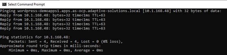
Step 9. Using a server, outside of the OCP cluster, verify that you can trace the route to the WordPress server using the following command:
tracert wordpress-demoapps1.apps.as-ocp.adaptive-solutions.local
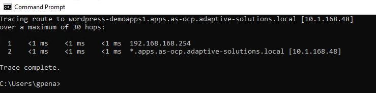
Step 10. On the WordPress home page, browse to the admin interface of WordPress by appending the URL with /admin and log in using the username and password you set during the Helm installation.
http:// http://wordpress-demoapps1.apps.as-ocp.adaptive-solutions.local/admin
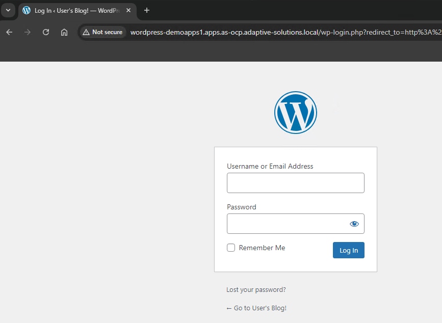
Step 11. Click Add a new page.
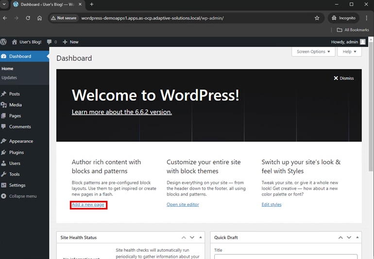
Step 12. Follow the instruction on the web page to create a blog post named “Cisco HV Demo”, and then publish the post.
Step 13. Navigate back to the default URL of the WordPress application to verify that your post was committed to the database.
http:// http://wordpress-demoapps1.apps.as-ocp.adaptive-solutions.local”
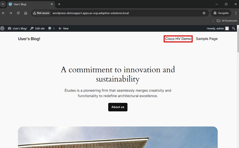
Step 14. Enter the following command on the OCP CLI:
oc get pods
[as-control@as-control ~]$ oc get pods
NAME READY STATUS RESTARTS AGE
wordpress-8546d6dbf8-cprcl 1/1 Running 0 4m44s
wordpress-mariadb-0 1/1 Running 0 4m44s
Step 15. Delete the pod/wordpress with the following command:
oc delete -f pod/wordpress-8546d6dbf8-cprcl
[as-control@as-control ~]$ oc delete pod wordpress-8546d6dbf8-cprcl
pod "wordpress-8546d6dbf8-cprcl" deleted
Step 16. Verify that a new pod is created with the following command:
oc get pods
[as-control@as-control ~]$ oc get pod
NAME READY STATUS RESTARTS AGE
wordpress-8546d6dbf8-thc6g 0/1 Init:0/1 0 11s
wordpress-mariadb-0 1/1 Running 0 5m14s
Step 17. Wait a few minutes for the new pod to complete startup , then using a browser within your test environment, enter the URL of the WordPress server (http) and the WordPress home page should display. Verify that your blog post has remained after the pod restart due to VSP persistent storage being available.
http:// http://wordpress-demoapps1.apps.as-ocp.adaptive-solutions.local
Cisco UCS has long brought the best computing CPU options to the modern data center, and this continues with options for GPUs in both Cisco UCS C-Series and X-Series servers to meet modern application needs. The options include a large set of NVIDIA GPUs for Cisco UCS M7 servers, but also includes a number of Intel GPUs to select from.
The Cisco UCS C240 rack server can support up to eight GPUs directly within the server chassis, and the single width Cisco UCS X-Series X210c can support two GPUs directly within the compute node. The Cisco UCS X210c and X410c compute nodes can be expanded with the Cisco UCS 9416 X-Fabric modules to extend their GPU capacity with the X440p PCIe nodes.
The Cisco UCS X440p PCIe node supports following GPU options:
▪ NVIDIA H100 Tensor Core GPU
▪ NVIDIA L40 GPU
▪ NVIDIA L40S GPU
▪ NVIDIA L4 Tensor Core GPU
▪ NVIDIA A100 Tensor Core GPU
▪ NVIDIA A16 GPU
▪ NVIDIA A40 GPU
▪ NVIDIA T4 Tensor Core GPU*
▪ Intel Data Center GPU Flex 140*
▪ Intel Data Center GPU Flex 170
*Also supported within the X210c front mezzanine slot. The placement of the X440p PCIe nodes must follow an alternating pattern of either being placed on odd slots, or on even slots.
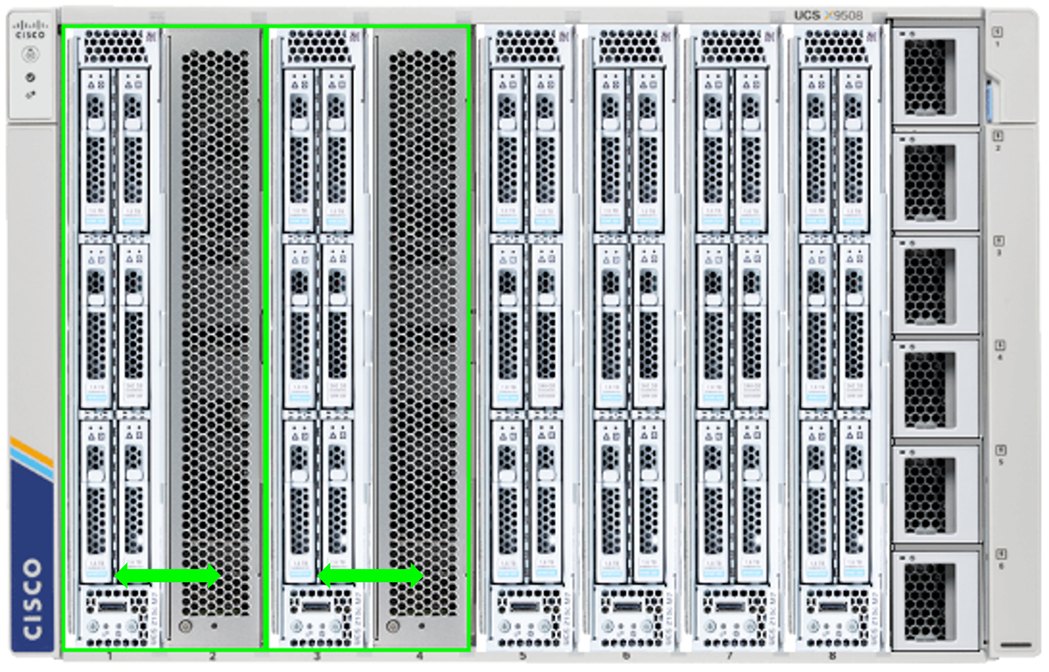
In an even slot orientation, the PCIe node will be extended through the 9416 X-Fabric with the odd compute slot preceding it.
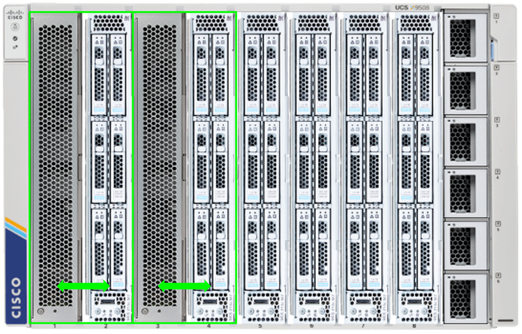
In an odd slot orientation, the PCIe node will be extended through the 9416 X-Fabric with the even compute slot following it.
The X440p PCIe node will connect through the 9416 X-Fabric into the computing node’s rear mezzanine card and will require a Cisco UCSX-V4-PCIME Mezz card for the server. This connectivity is established directly through Mezzanine connectors of both the Cisco UCS X-Series Server and the X440p PCIe node through the X-Fabric Modules as shown in Figure 14.
Figure 14. PCIe connectivity through X-Fabric
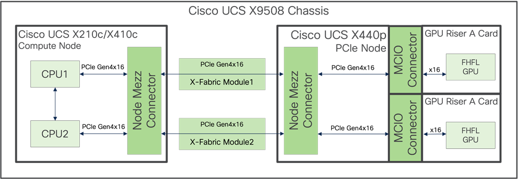
The GPU Riser A Card option for the X440p enables two full height, full length (FHFL) GPUs to be supported. up to four half height, half length (HHHL) options can be supported through swapping in the GPU Riser B Card option but will be at PCIe Gen4x8 for connectivity to the GPU.
With the X440p PCIe Node properly inserted, the GPUs will be seen associated to the server node in Intersight.
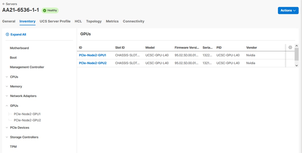
Additionally, these GPUs can now be seen within vCenter for the host.
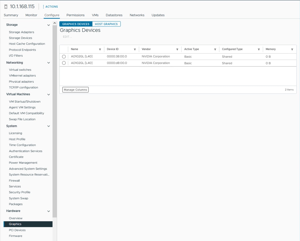
The GPUs will be made available to the worker nodes associated with the underlying ESXi host. The presentation of the mode will be made through VMware PCI PassThrough but can also be associated by installing the NVIDIA AI Enterprise (NVAIE) driver.
Procedure 1. Configure the X440p GPU within vSphere
Step 1. From the vSphere web client, go to Configure > Hardware > PCI Devices.
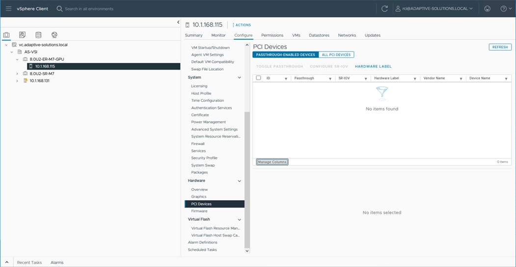
Step 2. Click ALL PCI DEVICES and enter the “L40” within the Device Name filter.
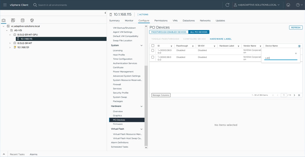
Step 3. Select both GPUs and click TOGGLE PASSTHROUGH.
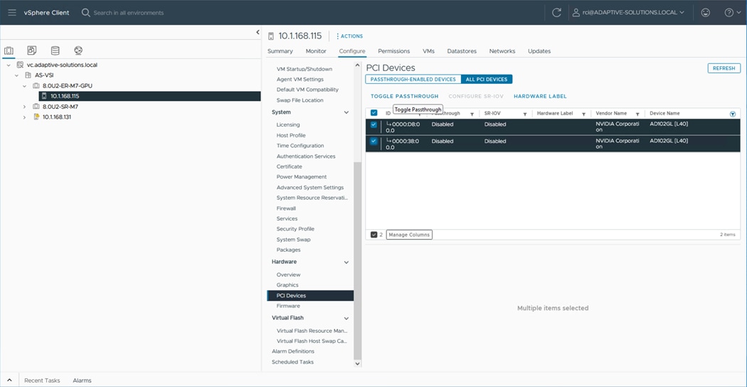
Step 4. Reboot the host.
Step 5. When the host is back up, shut down the worker node and migrate it to the host associated with the GPU.
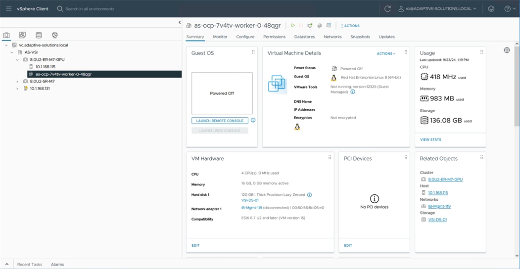
Step 6. Edit the virtual machine of the worker node with ACTIONS > Edit Settings…
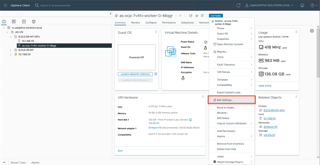
Step 7. With the Edit Settings dialogue window open, click ADD NEW DEVICE.
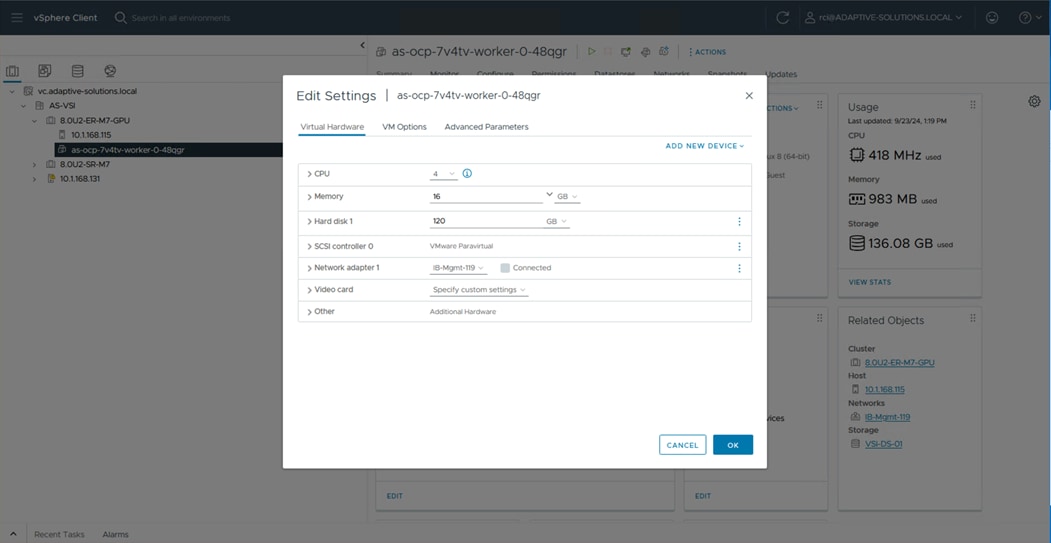
Step 8. Select PCI Device from the list.
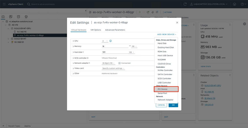
Step 9. Click the first L40 DirectPath IO listing and click SELECT.
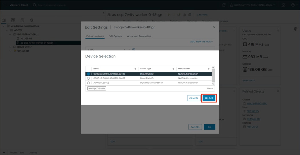
Step 10. Repeat this step for the second L40 Direct Path IO listing, then increase the CPU to 16 and the Memory to 64.
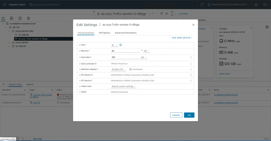
Step 11. Click Advanced Parameters in Edit Settings.
Step 12. Enter pciPassthru.use64bitMMIO as an Attribute, set the Value to True, and click ADD.
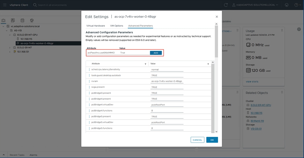
Step 13. Enter pciPassthru.64bitMMIOSizeGB as an Attribute, set the Value to 512, click ADD, then click OK.
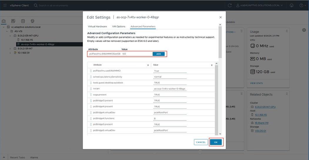
Step 14. Power the worker node VM back up.
Procedure 2. GPU Configuration within OCP
Step 1. Open the Console for the cluster, in our example it is https://console-openshift-console.adaptive-solutions.local.
Step 2. Go to Operators > OperatorHub.
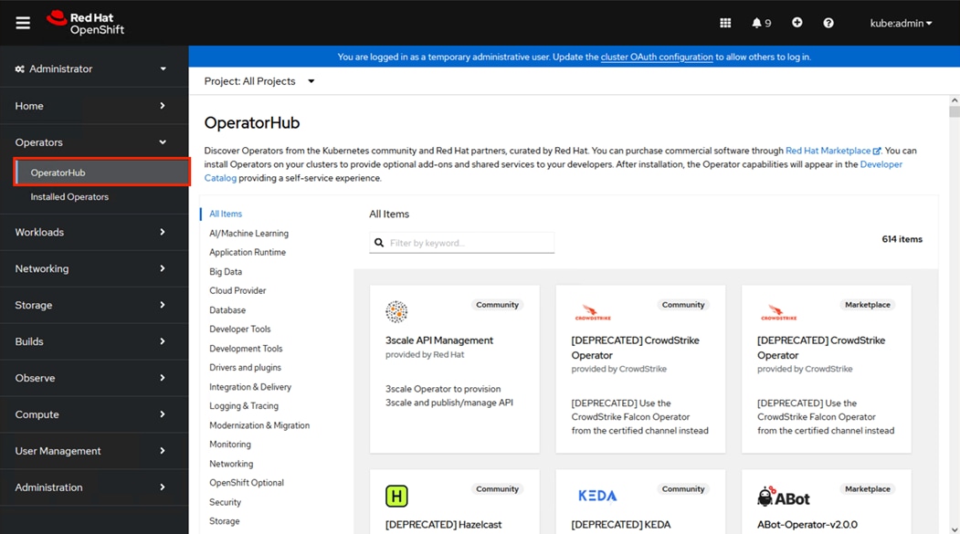
Step 3. Enter nfd in the Items search box to display the Node Feature Discovery Operator.
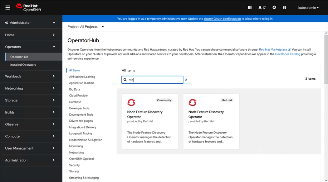
Step 4. Select the Red Hat offering. Click Install.
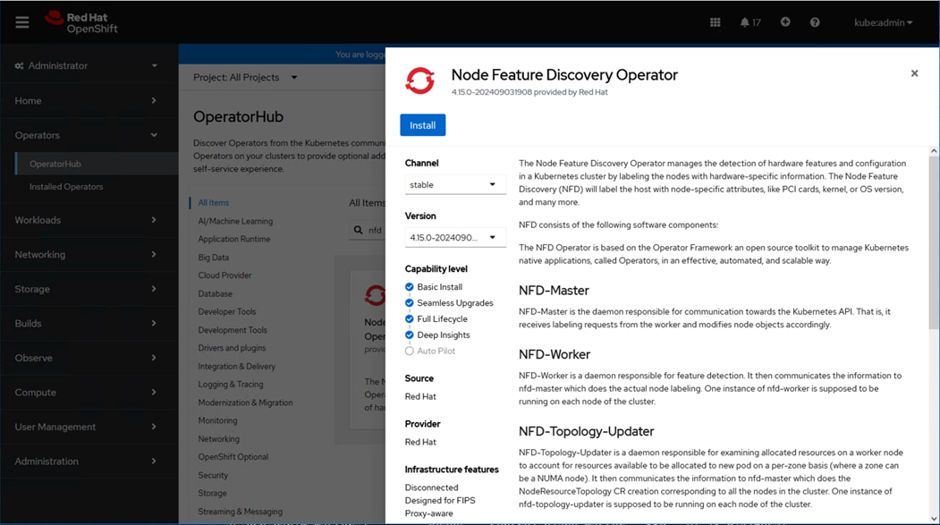
Step 5. Scroll down within the Install Operator dialogue and click Install.
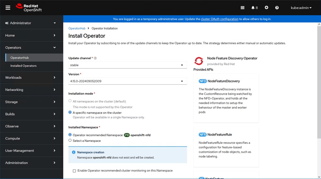
Step 6. Leaving default options selected, scroll down and click Install.
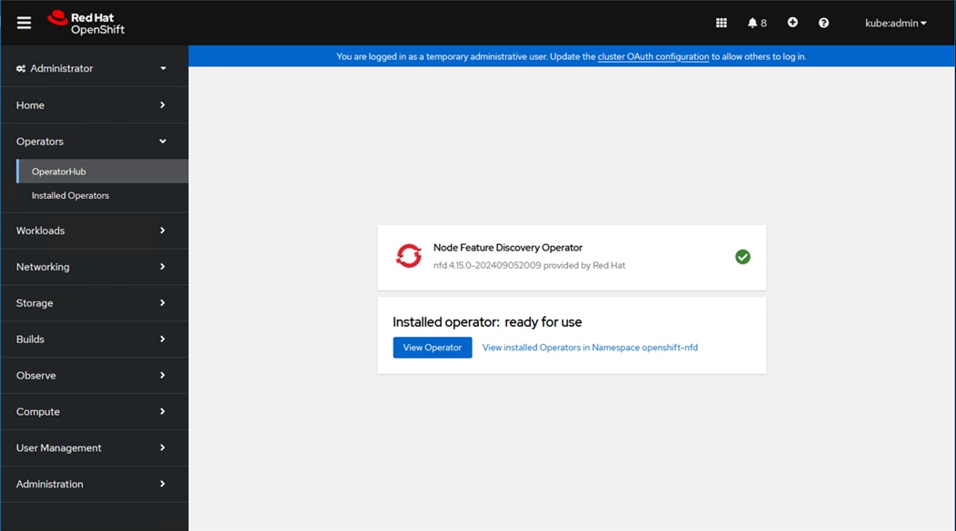
Step 7. After a couple minutes, the Operator will complete installation, click View Operator.
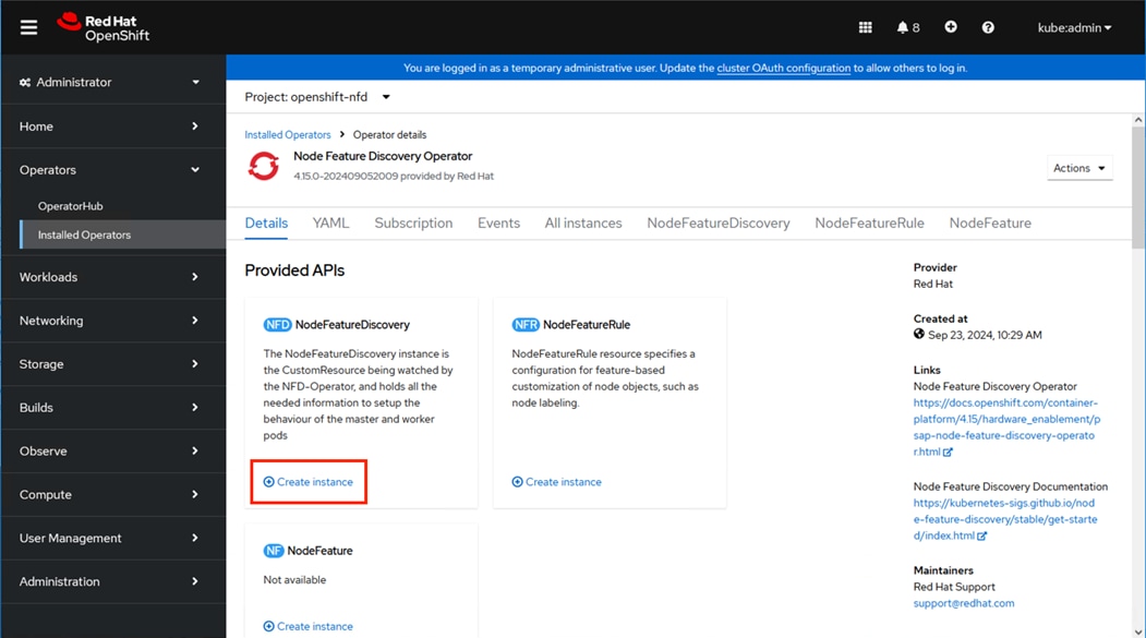
Step 8. Click Create within NodeFeatureDiscovery.
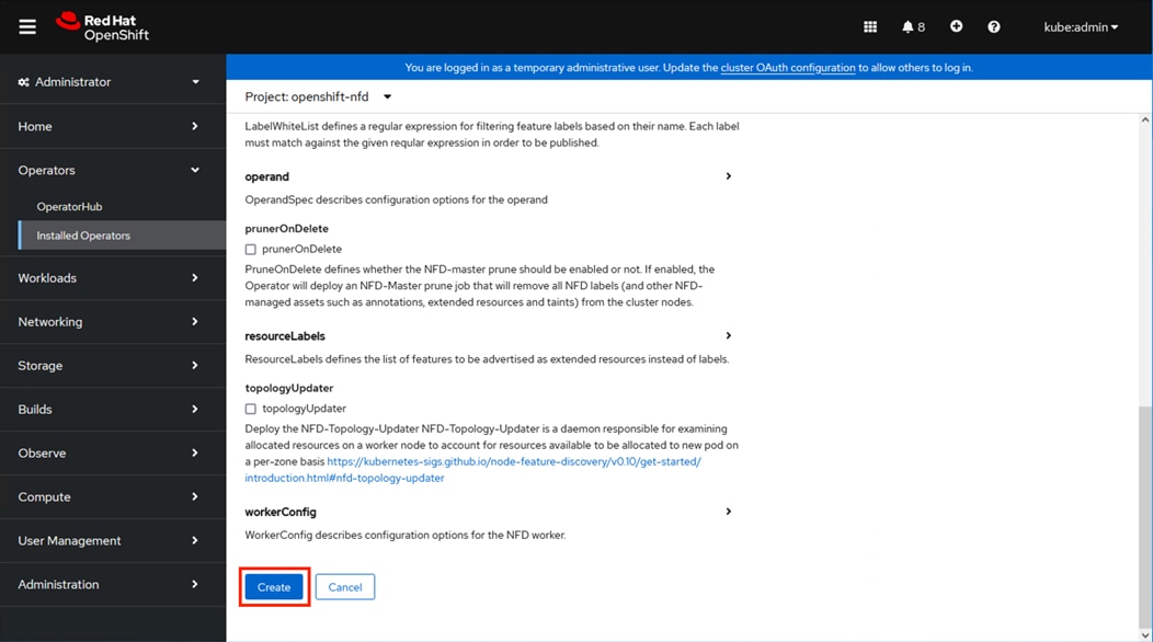
Step 9. Click Create.
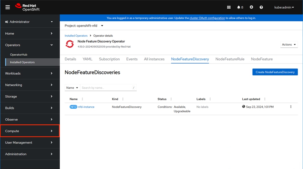
Step 10. Click Operators > OperatorHub.
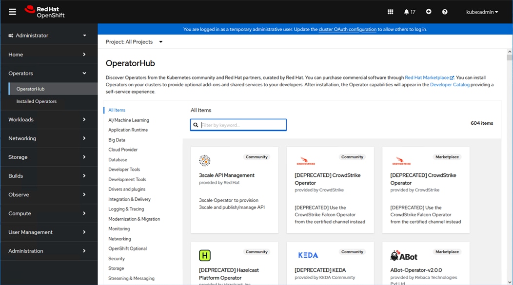
Step 11. Enter NVIDIA in the Items search box.
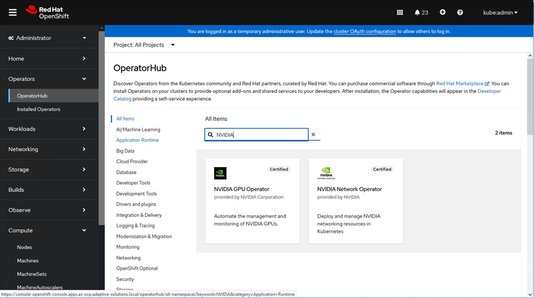
Step 12. Click the NVIDIA GPU Operator result and click Install.
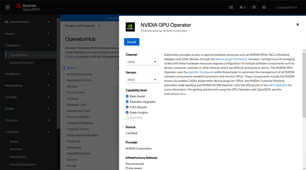
Step 13. Click Install.
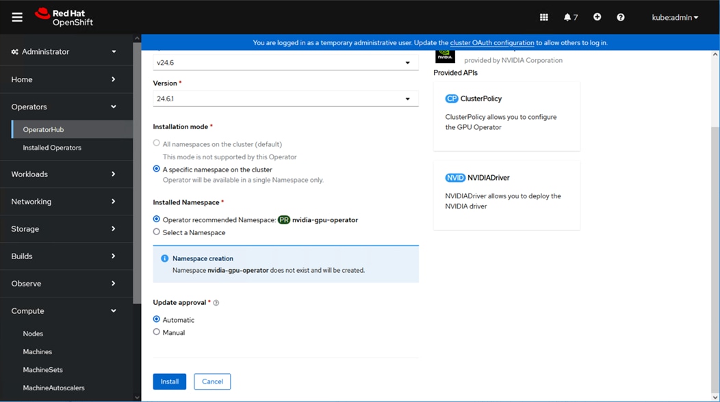
Step 14. Leave the defaults selected and click Install.

Step 15. When installation completes, click View Operator.
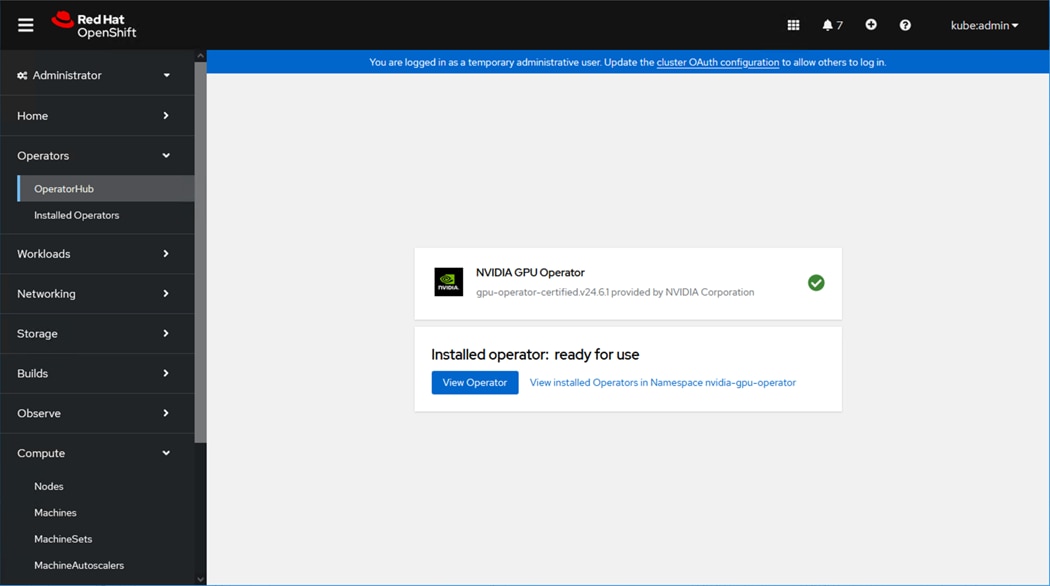
Step 16. Click the ClusterPolicy tab.
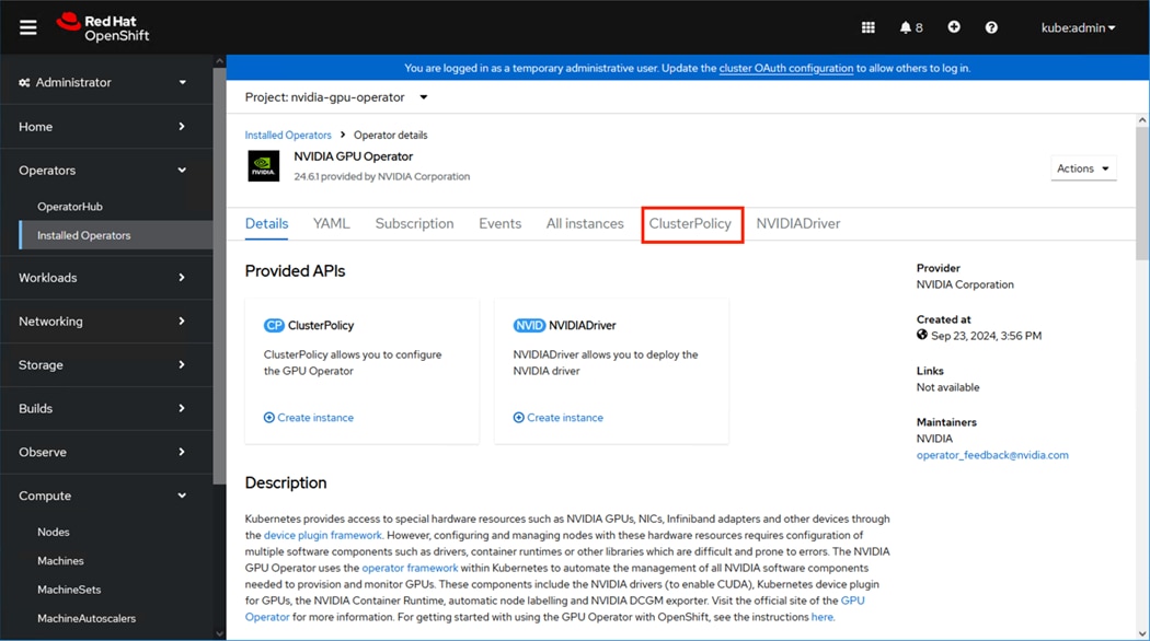
Step 17. Click Create ClusterPolicy.
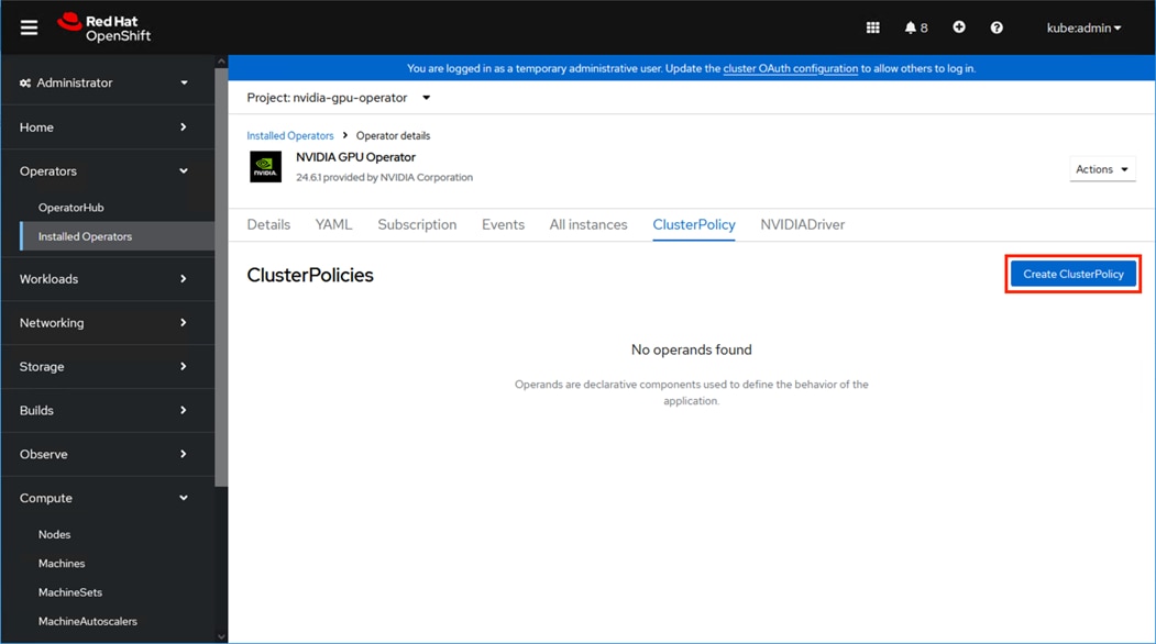
Step 18. Click Create.
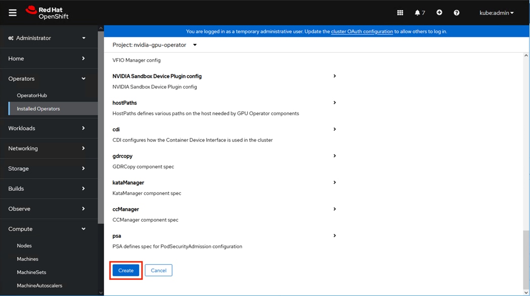
Step 19. Change to the nvidia-gpu-operator name space, and check for the state of the pods from your control host, waiting until all are in a running state.
[as-control@as-control ~]$ oc project nvidia-gpu-operator
Now using project "nvidia-gpu-operator" on server "https://api.as-ocp.adaptive-solutions.local:6443".
[as-control@as-control ~]$ oc get pods
NAME READY STATUS RESTARTS AGE
gpu-feature-discovery-j5mgw 1/1 Running 0 19m
gpu-operator-7799898b49-mvq92 1/1 Running 0 45h
nvidia-container-toolkit-daemonset-55dd8 1/1 Running 0 19m
nvidia-cuda-validator-hnmss 0/1 Completed 0 17m
nvidia-dcgm-exporter-vqvfq 1/1 Running 0 19m
nvidia-dcgm-tz4p7 1/1 Running 0 19m
nvidia-device-plugin-daemonset-6cx4g 1/1 Running 0 19m
nvidia-driver-daemonset-415.92.202405130844-0-54kjh 2/2 Running 2 23h
nvidia-node-status-exporter-j7djw 1/1 Running 2 23h
nvidia-operator-validator-ns4ps 1/1 Running 0 19m
Step 20. Check the SMI state for the listed nvidia-driver-daemonset.
[as-control@as-control ~]$ oc exec -it nvidia-driver-daemonset-415.92.202405130844-0-54kjh -- nvidia-smi
Wed Sep 25 17:32:31 2024
+-----------------------------------------------------------------------------------------+
| NVIDIA-SMI 550.90.07 Driver Version: 550.90.07 CUDA Version: 12.4 |
|-----------------------------------------+------------------------+----------------------+
| GPU Name Persistence-M | Bus-Id Disp.A | Volatile Uncorr. ECC |
| Fan Temp Perf Pwr:Usage/Cap | Memory-Usage | GPU-Util Compute M. |
| | | MIG M. |
|=========================================+========================+======================|
| 0 NVIDIA L40 On | 00000000:13:00.0 Off | 0 |
| N/A 32C P0 57W / 300W | 1MiB / 46068MiB | 0% Default |
| | | N/A |
+-----------------------------------------+------------------------+----------------------+
| 1 NVIDIA L40 On | 00000000:1C:00.0 Off | 0 |
| N/A 31C P0 37W / 300W | 1MiB / 46068MiB | 0% Default |
| | | N/A |
+-----------------------------------------+------------------------+----------------------+
+-----------------------------------------------------------------------------------------+
| Processes: |
| GPU GI CI PID Type Process name GPU Memory |
| ID ID Usage |
|=========================================================================================|
| No running processes found |
+-----------------------------------------------------------------------------------------+
Procedure 3. Deploy NVIDIA NIM Generative AI Container
This procedure provides an example of deploying NVIDIA Inference Microservices (NIM) to show the referencing of the GPUs in the solution. NIM is a is a set of inference microservices that is interfaced through standard APIs and is a part of NVAIE to utilize a large number of AI models including:
▪ large language models (LLM)
▪ image
▪ video
▪ automatic speech recognition (ASR)
▪ text-to-speech (TTS)
▪ vision-language models (VLM)
▪ biology
▪ retrieval
A deployment of NIM comes as a pre-configured container supported within OCP that we will deploy with Helm package manager from Red Hat. To install Helm, perform the following steps:
Step 1. Download helm:
[as-control@as-control ~]$ sudo curl -L https://mirror.openshift.com/pub/openshift-v4/clients/helm/latest/helm-linux-amd64 -o /usr/local/bin/helm
Step 2. Create the nim project:
[as-control@as-control nim-llm]$ oc new-project nim
Step 3. Set helm to be executable:
[as-control@as-control ~]$sudo chmod +x /usr/local/bin/helm
Step 4. Download NIM with password from NVIDIA license server:
helm fetch https://helm.ngc.nvidia.com/nim/charts/nim-llm-1.1.2.tgz --username=\$oauthtoken --password=Zxxxxxxxxxxxxxxxxxxxxxxxxxxxxxxxxxxxxxxxxxxxxxxxxxxxxxxxxxxxxxxxxxxxxxxxxxxxxxxxxxx3
tar xzvf nim-llm-1.1.2.tgz
cd nim-llm/
Step 5. Register the secret from the NVIDIA license server:
[as-control@as-control ~]$ oc create secret docker-registry ngc-secret --docker-server=nvcr.io --docker-username=\$oauthtoken --docker-password=Zxxxxxxxxxxxxxxxxxxxxxxxxxxxxxxxxxxxxxxxxxxxxxxxxxxxxxxxxxxxxxxxxxxxxxxxxxxxxxxxxxx3
secret/ngc-registry created
[as-control@as-control ~]$ oc create secret generic ngc-api --from-literal=NGC_CLI_API_KEY=Zxxxxxxxxxxxxxxxxxxxxxxxxxxxxxxxxxxxxxxxxxxxxxxxxxxxxxxxxxxxxxxxxxxxxxxxxxxxxxxxxxx3
secret/ngc-api created
Step 6. Edit the file values.yaml and change the following entries:
Within “persistence:”
enabled: false
storageClass: ""
size: 50Gi
to
enabled: true
storageClass: "thin-csi"
size: 500Gi
Within “initContainers:”
ngcInit: {} # disabled by default
to
ngcInit: {} # disabled by default
secretName: NGC_API_KEY
Step 7. Establish privileges for the install:
[as-control@as-control nim-llm]$ oc adm policy add-scc-to-user anyuid -z default
[as-control@as-control nim-llm]$ oc adm policy add-scc-to-user privileged -z default
Step 8. Install NIM:
helm install test-nim .
Step 9. Adjust the NIM service to point to the specific node:
oc edit svc test-nim-nim-llm
Step 10. Find within spec: section and change:
type: ClusterIP
to
type: NodePort
Step 11. Save the test-nim-nim-llm changes.
Step 12. Adjust the ngc-api secret:
[as-control@as-control nim-llm]$ oc edit secret ngc-api
Step 13. Change this line:
NGC_CLI_API_KEY: Wxxxxxxxxxxxxxxxxxxxxxxxxxxxxxxxxxxxxxxxxxxxxxxxxxxxxxxxxxxxxxxxxxxxxxxxxxxxxxxxxxxz
to
NGC_API_KEY: Wxxxxxxxxxxxxxxxxxxxxxxxxxxxxxxxxxxxxxxxxxxxxxxxxxxxxxxxxxxxxxxxxxxxxxxxxxxxxxxxxxxz
Step 14. Find the nvidia-driver-daemonset:
[as-control@as-control nim-llm]$ oc project nvidia-gpu-operator
[as-control@as-control nim-llm]$ oc get pods
NAME READY STATUS RESTARTS AGE
gpu-feature-discovery-qpzj4 1/1 Running 0 59m
gpu-operator-8574669bc6-2c5kc 1/1 Running 0 61m
nvidia-container-toolkit-daemonset-vnlpf 1/1 Running 0 59m
nvidia-cuda-validator-4nxft 0/1 Completed 0 59m
nvidia-dcgm-exporter-mbfjc 1/1 Running 0 59m
nvidia-dcgm-xjh6x 1/1 Running 0 59m
nvidia-device-plugin-daemonset-v8r8w 1/1 Running 0 59m
nvidia-driver-daemonset-415.92.202405130844-0-54kjh 2/2 Running 2 25h
nvidia-node-status-exporter-fqnxm 1/1 Running 0 59m
nvidia-operator-validator-fbt2f 1/1 Running 0 59m
Step 15. GPU Prior to NIM install, memory and GPU-Util inactive, no running processes can be found:
[as-control@as-control ~]$ oc exec -it nvidia-driver-daemonset-415.92.202405130844-0-vtb6d -- nvidia-smi
Thu Aug 29 14:35:13 2024
+-----------------------------------------------------------------------------------------+
| NVIDIA-SMI 550.90.07 Driver Version: 550.90.07 CUDA Version: 12.4 |
|-----------------------------------------+------------------------+----------------------+
| GPU Name Persistence-M | Bus-Id Disp.A | Volatile Uncorr. ECC |
| Fan Temp Perf Pwr:Usage/Cap | Memory-Usage | GPU-Util Compute M. |
| | | MIG M. |
|=========================================+========================+======================|
| 0 NVIDIA L40 On | 00000000:13:00.0 Off | 0 |
| N/A 31C P8 37W / 300W | 4MiB / 46068MiB | 0% Default |
| | | N/A |
+-----------------------------------------+------------------------+----------------------+
| 1 NVIDIA L40 On | 00000000:1C:00.0 Off | 0 |
| N/A 31C P8 38W / 300W | 4MiB / 46068MiB | 0% Default |
| | | N/A |
+-----------------------------------------+------------------------+----------------------+
+-----------------------------------------------------------------------------------------+
| Processes: |
| GPU GI CI PID Type Process name GPU Memory |
| ID ID Usage |
|=========================================================================================|
| No running processes found |
+-----------------------------------------------------------------------------------------+
NIM installed, consuming 42795MiB/46068MiB with GPU-Util inactive, python 3 showing up under Processes:
[as-control@as-control ~]$ oc -n nvidia-gpu-operator exec -it nvidia-driver-daemonset-415.92.202405130844-0-vtb6d -- nvidia-smi
Thu Aug 29 15:06:12 2024
+-----------------------------------------------------------------------------------------+
| NVIDIA-SMI 550.90.07 Driver Version: 550.90.07 CUDA Version: 12.4 |
|-----------------------------------------+------------------------+----------------------+
| GPU Name Persistence-M | Bus-Id Disp.A | Volatile Uncorr. ECC |
| Fan Temp Perf Pwr:Usage/Cap | Memory-Usage | GPU-Util Compute M. |
| | | MIG M. |
|=========================================+========================+======================|
| 0 NVIDIA L40 On | 00000000:13:00.0 Off | 0 |
| N/A 44C P0 93W / 300W | 42795MiB / 46068MiB | 0% Default |
| | | N/A |
+-----------------------------------------+------------------------+----------------------+
| 1 NVIDIA L40 On | 00000000:1C:00.0 Off | 0 |
| N/A 32C P8 64W / 300W | 1MiB / 46068MiB | 0% Default |
| | | N/A |
+-----------------------------------------+------------------------+----------------------+
+-----------------------------------------------------------------------------------------+
| Processes: |
| GPU GI CI PID Type Process name GPU Memory |
| ID ID Usage |
|=========================================================================================|
| 0 N/A N/A 51610 C python3 42784MiB |
+-----------------------------------------------------------------------------------------+
Step 16. Find out the service port used for the NIM instance.
[as-control@as-control nim-llm]$ oc get svc
NAME TYPE CLUSTER-IP EXTERNAL-IP PORT(S) AGE
test-nim-nim-llm NodePort 172.30.53.161 <none> 8000:31879/TCP 3m14s
test-nim-nim-llm-sts ClusterIP None <none> 8000/TCP 3m14s
Prompt submitted to NIM, specifying the IP of the worker node with NIM/GPU, asking as an example of vacation ideas in Spain using port 31879:
[as-control@as-control nim-llm]$ curl -X 'POST' \
'http://10.1.168.23:31879/v1/chat/completions' \
-H 'accept: application/json' \
-H 'Content-Type: application/json' \
-d '{
"messages": [
{
"content": "You are a polite and respectful chatbot helping people plan a vacation.",
"role": "system"
},
{
"content": "What should I do for a 4 day vacation in Spain?",
"role": "user"
}
],
"model": "meta/llama3-8b-instruct",
"max_tokens": 160,
"top_p": 1,
"n": 1,
"stream": false,
"frequency_penalty": 0.0
}'
NIM response:
{"id":"cmpl-c2bdd62492e94b4cbe81011eff89f504","object":"chat.completion","created":1724943123,"model":"meta/llama3-8b-instruct","choices":[{"index":0,"message":{"role":"assistant","content":"°hola! Spain is a wonderful destination for a 4-day vacation! With so much history, culture, and beauty to explore, I'd be happy to help you plan your trip.\n\nHere are a few options, depending on your interests:\n\n**Option 1: Discover Madrid and Its Surroundings**\n\n* Day 1: Explore Madrid's historic center, visit the Royal Palace, and stroll through the Retiro Park.\n* Day 2: Visit the nearby city of Segovia, famous for its Roman aqueduct and Gothic cathedral.\n* Day 3: Head to the charming town of Toledo, a UNESCO World Heritage Site, known for its medieval architecture and rich cultural heritage.\n* Day 4: Return to Madrid and visit the Prado Museum, one of the world's greatest"},"logprobs":null,"finish_reason":"length","stop_reason":null}],"usage":{"prompt_tokens":42,"total_tokens":202,"completion_tokens":160}}[as-control@as-control nim-llm]$
Formatted result from response:
hola! Spain is a wonderful destination for a 4-day vacation! With so much history, culture, and beauty to explore, I'd be happy to help you plan your trip.
Here are a few options, depending on your interests:
**Option 1: Discover Madrid and Its Surroundings**
* Day 1: Explore Madrid's historic center, visit the Royal Palace, and stroll through the Retiro Park.
* Day 2: Visit the nearby city of Segovia, famous for its Roman aqueduct and Gothic cathedral.
* Day 3: Head to the charming town of Toledo, a UNESCO World Heritage Site, known for its medieval architecture and rich cultural heritage.
* Day 4: Return to Madrid and visit the Prado Museum, one of the world's greatest
NIM status during prompt running, memory utilization stays the same, but GPU-Util is seen to be at 99%:
[as-control@as-control ~]$ oc -n nvidia-gpu-operator exec -it nvidia-driver-daemonset-415.92.202405130844-0-vtb6d -- nvidia-smi
Thu Aug 29 15:06:30 2024
+-----------------------------------------------------------------------------------------+
| NVIDIA-SMI 550.90.07 Driver Version: 550.90.07 CUDA Version: 12.4 |
|-----------------------------------------+------------------------+----------------------+
| GPU Name Persistence-M | Bus-Id Disp.A | Volatile Uncorr. ECC |
| Fan Temp Perf Pwr:Usage/Cap | Memory-Usage | GPU-Util Compute M. |
| | | MIG M. |
|=========================================+========================+======================|
| 0 NVIDIA L40 On | 00000000:13:00.0 Off | 0 |
| N/A 49C P0 246W / 300W | 42795MiB / 46068MiB | 99% Default |
| | | N/A |
+-----------------------------------------+------------------------+----------------------+
| 1 NVIDIA L40 On | 00000000:1C:00.0 Off | 0 |
| N/A 31C P8 37W / 300W | 1MiB / 46068MiB | 0% Default |
| | | N/A |
+-----------------------------------------+------------------------+----------------------+
+-----------------------------------------------------------------------------------------+
| Processes: |
| GPU GI CI PID Type Process name GPU Memory |
| ID ID Usage |
|=========================================================================================|
| 0 N/A N/A 51610 C python3 42784MiB |
+-----------------------------------------------------------------------------------------+
Cisco Intersight: https://www.intersight.com
Cisco Intersight Managed Mode: https://www.cisco.com/c/en/us/td/docs/unified_computing/Intersight/b_Intersight_Managed_Mode_Configuration_Guide.html
Cisco Unified Computing System: https://www.cisco.com/site/us/en/products/computing/servers-unified-computing-systems/index.html
Cisco UCS 6536 Fabric Interconnects: https://www.cisco.com/c/en/us/products/collateral/servers-unified-computing/ucs6536-fabric-interconnect-ds.html
NVIDIA AI: https://www.nvidia.com/en-us/ai/
Network
Cisco Nexus 9000 Series Switches: http://www.cisco.com/c/en/us/products/switches/nexus-9000-series-switches/index.html
Cisco MDS 9124V Switches: https://www.cisco.com/c/en/us/products/collateral/storage-networking/mds-9100-series-multilayer-fabric-switches/mds-9124v-fibre-channel-switch-ds.html
Cisco Nexus Dashboard Fabric Controller: https://www.cisco.com/c/en/us/products/collateral/cloud-systems-management/prime-data-center-network-manager/nb-06-ndfc-ds-cte-en.html
Hitachi Virtual Storage Platform E Series: https://www.hitachivantara.com/en-us/products/storage-platforms/primary-block-storage/vsp-e-series.html
Hitachi Virtual Storage Platform 5000 Series: https://www.hitachivantara.com/en-us/products/storage-platforms/primary-block-storage/vsp-5000-series.html
Hitachi SVOS: https://www.hitachivantara.com/en-us/products/storage-platforms/primary-block-storage/virtualization-operating-system.html
Hitachi Ops Center: https://www.hitachivantara.com/en-us/products/storage-software/ai-operations-management/ops-center.html
Red Hat OpenShift: https://www.redhat.com/en/technologies/cloud-computing/openshift
OpenShift v4 on vSphere – Common Practices and Recommendations: https://access.redhat.com/articles/7057811
VMware vSphere Container Storage Plug-in: https://docs.vmware.com/en/VMware-vSphere-Container-Storage-Plug-in/index.html
Red Hat Ansible: https://www.ansible.com/
Cisco UCS Hardware Compatibility Matrix: https://ucshcltool.cloudapps.cisco.com/public/
Hitachi Product Compatibility Guide: https://compatibility.hitachivantara.com/
For comments and suggestions about this guide and related guides, join the discussion on Cisco Community at https://cs.co/en-cvds.
CVD Program
ALL DESIGNS, SPECIFICATIONS, STATEMENTS, INFORMATION, AND RECOMMENDATIONS (COLLECTIVELY, "DESIGNS") IN THIS MANUAL ARE PRESENTED "AS IS," WITH ALL FAULTS. CISCO AND ITS SUPPLIERS DISCLAIM ALL WARRANTIES, INCLUDING, WITHOUT LIMITATION, THE WARRANTY OF MERCHANTABILITY, FITNESS FOR A PARTICULAR PURPOSE AND NONINFRINGEMENT OR ARISING FROM A COURSE OF DEALING, USAGE, OR TRADE PRACTICE. IN NO EVENT SHALL CISCO OR ITS SUPPLIERS BE LIABLE FOR ANY INDIRECT, SPECIAL, CONSEQUENTIAL, OR INCIDENTAL DAMAGES, INCLUDING, WITHOUT LIMITATION, LOST PROFITS OR LOSS OR DAMAGE TO DATA ARISING OUT OF THE USE OR INABILITY TO USE THE DESIGNS, EVEN IF CISCO OR ITS SUPPLIERS HAVE BEEN ADVISED OF THE POSSIBILITY OF SUCH DAMAGES.
THE DESIGNS ARE SUBJECT TO CHANGE WITHOUT NOTICE. USERS ARE SOLELY RESPONSIBLE FOR THEIR APPLICATION OF THE DESIGNS. THE DESIGNS DO NOT CONSTITUTE THE TECHNICAL OR OTHER PROFESSIONAL ADVICE OF CISCO, ITS SUPPLIERS OR PARTNERS. USERS SHOULD CONSULT THEIR OWN TECHNICAL ADVISORS BEFORE IMPLEMENTING THE DESIGNS. RESULTS MAY VARY DEPENDING ON FACTORS NOT TESTED BY CISCO.
CCDE, CCENT, Cisco Eos, Cisco Lumin, Cisco Nexus, Cisco StadiumVision, Cisco TelePresence, Cisco WebEx, the Cisco logo, DCE, and Welcome to the Human Network are trademarks; Changing the Way We Work, Live, Play, and Learn and Cisco Store are service marks; and Access Registrar, Aironet, AsyncOS, Bringing the Meeting To You, Catalyst, CCDA, CCDP, CCIE, CCIP, CCNA, CCNP, CCSP, CCVP, Cisco, the Cisco Certified Internetwork Expert logo, Cisco IOS, Cisco Press, Cisco Systems, Cisco Systems Capital, the Cisco Systems logo, Cisco Unified Computing System (Cisco UCS), Cisco UCS B-Series Blade Servers, Cisco UCS C-Series Rack Servers, Cisco UCS S-Series Storage Servers, Cisco UCS X-Series, Cisco UCS Manager, Cisco UCS Management Software, Cisco Unified Fabric, Cisco Application Centric Infrastructure, Cisco Nexus 9000 Series, Cisco Nexus 7000 Series. Cisco Prime Data Center Network Manager, Cisco NX-OS Software, Cisco MDS Series, Cisco Unity, Collaboration Without Limitation, EtherFast, EtherSwitch, Event Center, Fast Step, Follow Me Browsing, FormShare, GigaDrive, HomeLink, Internet Quotient, IOS, iPhone, iQuick Study, LightStream, Linksys, MediaTone, MeetingPlace, MeetingPlace Chime Sound, MGX, Networkers, Networking Academy, Network Registrar, PCNow, PIX, PowerPanels, ProConnect, ScriptShare, SenderBase, SMARTnet, Spectrum Expert, StackWise, The Fastest Way to Increase Your Internet Quotient, TransPath, WebEx, and the WebEx logo are registered trade-marks of Cisco Systems, Inc. and/or its affiliates in the United States and certain other countries. (LDW_E5)
All other trademarks mentioned in this document or website are the property of their respective owners. The use of the word partner does not imply a partnership relationship between Cisco and any other company. (0809R)