Cisco and Hitachi Adaptive Solutions with Cisco UCS X-Series, VMware 8U1, and Hitachi VSP 5600
Available Languages
Bias-Free Language
The documentation set for this product strives to use bias-free language. For the purposes of this documentation set, bias-free is defined as language that does not imply discrimination based on age, disability, gender, racial identity, ethnic identity, sexual orientation, socioeconomic status, and intersectionality. Exceptions may be present in the documentation due to language that is hardcoded in the user interfaces of the product software, language used based on RFP documentation, or language that is used by a referenced third-party product. Learn more about how Cisco is using Inclusive Language.
- US/Canada 800-553-2447
- Worldwide Support Phone Numbers
- All Tools
 Feedback
 Feedback
Published: January 2024
In partnership with:
![]()
About the Cisco Validated Design Program
The Cisco Validated Design (CVD) program consists of systems and solutions designed, tested, and documented to facilitate faster, more reliable, and more predictable customer deployments. For more information, go to: http://www.cisco.com/go/designzone.
Cisco Validated Designs consist of systems and solutions that are designed, tested, and documented to facilitate and improve customer deployments. These designs incorporate a wide range of technologies and products into a portfolio of solutions that have been developed to address the business needs of our customers.
Cisco and Hitachi have joined forces to provide a converged infrastructure solution designed to address the current challenges faced by enterprise businesses and position them for future success. Drawing upon their extensive industry knowledge and innovative technology, this collaborative Cisco CVD presents a robust, flexible, and agile foundation for today's businesses. Moreover, the partnership between Cisco and Hitachi goes beyond a singular solution, allowing businesses to leverage their ambitious roadmap of progressive technologies including advanced analytics, IoT, cloud, and edge capabilities. By partnering with Cisco and Hitachi, organizations can confidently embark on their modernization journey and position themselves to capitalize on emerging business opportunities facilitated by groundbreaking technology.
This document explains the deployment of the Cisco and Hitachi Adaptive Solutions for Converged Infrastructure as a Virtual Server Infrastructure (VSI), as it was described in the Cisco and Hitachi Adaptive Solutions with Cisco UCSX, VMware 8U1, and Hitachi VSP 5600 Design Guide. The recommended solution architecture is built on Cisco Unified Computing System (Cisco UCS) using the unified software release to support the Cisco UCS hardware platforms for Cisco UCS X series servers, Cisco UCS 6500 Fabric Interconnects, Cisco Nexus 9000 Series switches, Cisco MDS Fibre channel switches, and the Hitachi Virtual Storage Platform (VSP) 5600. This architecture is implemented on VMware vSphere 8.0 U1 to support the leading virtual server platform of enterprise customers.
Additional Cisco Validated Designs created in a partnership between Cisco and Hitachi can be found here: https://www.cisco.com/c/en/us/solutions/design-zone/data-center-design-guides/data-center-design-guides-all.html#Hitachi
This chapter contains the following:
● Audience
Modernizing your data center can be overwhelming, and it’s vital to select a trusted technology partner with proven expertise. With Cisco and Hitachi as partners, companies can build for the future by enhancing systems of record, supporting systems of innovation, and growing their business. Organizations need an agile solution, free from operational inefficiencies, to deliver continuous data availability, meet SLAs, and prioritize innovation.
Cisco and Hitachi Adaptive Solutions for Converged Infrastructure as a Virtual Server Infrastructure (VSI) is a best practice datacenter architecture built on the collaboration of Hitachi Vantara and Cisco to meet the needs of enterprise customers utilizing virtual server workloads. This architecture is composed of the Hitachi Virtual Storage Platform (VSP) 5000 series connecting through the Cisco MDS multilayer switches supporting both FC-SCSI and FC-NVMe protocols to Cisco Unified Computing System X-Series Servers managed through Cisco Intersight, and further enabled with the Cisco Nexus family of switches.
These deployment instructions are based on the buildout of the Cisco and Hitachi Adaptive Solutions for Converged Infrastructure validated reference architecture, which describes the specifics of the products utilized within the Cisco validation lab, but the solution is considered relevant for equivalent supported components listed within Cisco and Hitachi Vantara’s published compatibility matrixes. Supported adjustments from the example validated build must be evaluated with care as their implementation instructions may differ.
The intended audience of this document includes but is not limited to IT architects, sales engineers, field consultants, professional services, IT managers, partner engineering, and customers who want to take advantage of an infrastructure built to deliver IT efficiency and enable IT innovation.
This document provides a step by step configuration and implementation guide for the Cisco and Hitachi Adaptive Solutions for the Converged Infrastructure solution. This solution features a validated reference architecture composed of:
● Cisco UCS Compute
● Cisco Nexus Switches
● Cisco Multilayer SAN Switches
● Hitachi Virtual Storage Platform
For the design decisions and technology discussion of the solution, please refer to the Cisco and Hitachi Adaptive Solutions for Converged Infrastructure Design Guide: https://www.cisco.com/c/en/us/td/docs/unified_computing/ucs/UCS_CVDs/hitachi_adaptive_vmware_vsp_design.html
The following design elements distinguish this version of the Adaptive Solutions Virtual Server Infrastructure from previous models:
● Cisco UCS X210c M7 servers with Intel Xeon Scalable Processors with up to 60 cores per processor and up to 8TB of DDR-4800 DIMMs
● 100Gbps Ethernet and 32Gbps Fibre Channel in Adaptive Solutions
● Integration of the 5th Generation Cisco UCS 6536 Fabric Interconnect into Adaptive Solutions
● Integration of the 5th Generation Cisco UCS 15000-series VICs into Adaptive Solutions
● Integration of the Cisco UCS X9108-100G Intelligent Fabric Module into the Cisco UCS X-Series X9508 Chassis
● Deployment of Cisco UCS with Cisco Intersight Managed Mode (IMM)
● Nexus Dashboard Fabric Controller
● VMware vSphere 8.0 Update 1
● FC-NVMe connectivity
● VMware vVols Datastores
● Hitachi Virtual Storage Platform (VSP) 5600
● Hitachi Ops Center release version 10.9.3
● Hitachi Storage Provider for VMware vCenter release version 3.7.3
Deployment Hardware and Software
This chapter contains the following:
The Adaptive Solutions Virtual Server Infrastructure consists of a high-performance Fibre Channel network built using the following hardware components:
● Cisco UCS X9508 Chassis with Cisco UCSX-I-9108-100G Intelligent Fabric Modules (IFMs) and up to eight Cisco UCS X210c M7 Compute Nodes with 4th Generation Intel Xeon Scalable CPUs.
● Fifth-generation Cisco UCS 6536 Fabric Interconnects to support 100GbE, 25GbE, and 32GFC connectivity as needed.
● High-speed Cisco NX-OS-based Nexus 93600CD-GX switching design to support up to 100GE .
● Hitachi 5600 Virtual Storage Platform NVMe storage with 32G Fibre Channel connectivity.
● Cisco MDS 9124V switches to support Fibre Channel storage configuration.
The software components of the solution consist of:
● Cisco Intersight SaaS platform to deploy, maintain and support the Adaptive Solutions infrastructure.
● Cisco Intersight Assist Virtual Appliance to connect the Hitachi VSP 5600, VMware vCenter, and Cisco Nexus and MDS switches with Cisco Intersight.
● Cisco Nexus Dashboard Fabric Controller to give expanded insight and management into the MDS switching.
● Hitachi Ops Center Administrator is an infrastructure management solution that unifies storage provisioning, data protection, and storage management.
● Hitachi Ops Center API Configuration Manager to help connect the Hitachi VSP 5600 to the Intersight platform.
● VMware vCenter to set up and manage the virtual infrastructure as well as Cisco Intersight integration.
Figure 1 shows the validated hardware components and connections used in the Adaptive Solutions Virtual Server Infrastructure design.
Figure 1. Adaptive Solutions Virtual Server Infrastructure Physical Topology
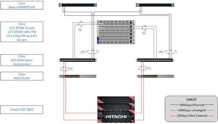
The reference hardware configuration includes:
● Two Cisco Nexus 93600CD-GX Switches in Cisco NX-OS mode provide the switching fabric.
● Two Cisco UCS 6536 Fabric Interconnects (FI) provide the chassis connectivity. One 100 Gigabit Ethernet port from each FI, configured as a Port-Channel, is connected to each 93600CD-GX. Four FC ports are connected to the Cisco MDS 9124V switches via breakout using 32-Gbps Fibre Channel connections configured as a single port channel for SAN connectivity.
● One Cisco UCS X9508 Chassis connects to fabric interconnects using Cisco UCSX 9108-100G Intelligent Fabric Modules (IFMs), where four 100 Gigabit Ethernet ports are used on each IFM to connect to the appropriate FI. If additional bandwidth is required, all eight 100G ports can be utilized.
● The Cisco MDS 9124V sits between the compute and storage delivering 32Gbps Fibre Channel connectivity, as well as interfacing to resources present in an existing data center.
● The Hitachi VSP 5600 controllers connect with two 32Gbps FC ports from each controller to each Cisco MDS 9124V for delivering to the SAN network.
Table 1 lists the software revisions for various components of the solution.
| Layer |
Device |
Image |
Comments |
| Network |
Cisco Nexus 93600CD-GXNX-OS |
10.2(5)M |
|
| Cisco MDS 9124V |
9.3(2) |
Requires SMART Licensing |
|
| Nexus Dashboard |
2.3(2d) |
|
|
| Cisco Nexus Dashboard Fabric Controller |
12.1.2e on Nexus Dashboard 2.3(2d) |
|
|
| Compute |
Cisco UCS Fabric Interconnect 6536 and UCS 9108-100G IFM |
4.3(2b) |
Cisco UCS GA release for infrastructure including FIs and IOM/IFM. |
| Cisco UCS X210c M7 |
5.1(1.230052) |
|
|
| Cisco UCS C220 M7 |
5.1(1.230052) |
Connected but not a focus in the validation. |
|
| Cisco UCS Tools |
1.3.3-1OEM |
|
|
| VMware ESXi nfnic FC Driver |
5.0.0.41 |
Supports FC-NVMe |
|
| VMware ESXi nenic Ethernet Driver |
2.0.11.0 |
|
|
| VMware ESXi |
8.0 Update 1a |
Build 21813344 included in Cisco Custom ISO, updated with patch 8.0 Update 1c |
|
| VMware vCenter Appliance |
8.0 Update 1c |
Build 20395099 |
|
| Cisco Intersight Assist Appliance |
1.0.9-588 |
1.0.9-588 initially installed and then automatically upgraded |
|
| Storage |
Hitachi VSP 5600 |
SVOS 90-09-21-00/01 |
|
| Hitachi Ops Center Administrator/CM Rest |
10.9.3 |
|
|
|
|
Hitachi Storage Provider for VMware vCenter |
3.7.3 |
|
Table 2 lists the VLANs that are configured in the environment and details their usage.
| VLAN ID |
Name |
Usage |
IP Subnet used in this deployment |
| 2 |
Native-VLAN |
Use VLAN 2 as native VLAN instead of default VLAN (1). |
|
| 19 |
OOB-MGMT-VLAN |
Out-of-band management VLAN to connect management ports for various devices |
192.168.168.0/24; GW: 192.168.168.254 |
| 119 |
IB-MGMT-VLAN |
In-band management VLAN utilized for all in-band management connectivity - for example, ESXi hosts, VM management, and so on. |
10.1.168.0/24; GW: 10.1.168.254 |
| 1000 |
vMotion |
VMware vMotion traffic |
10.0.0.0/24 * |
| 1100 |
VM-Traffic |
VM data traffic sourced from FI-A and FI-B |
10.1.100.0/24; GW: 10.1.100.254 |
| 1101 |
VM-Traffic-A |
VM data traffic sourced from FI-A |
10.1.101.0/24; GW: 10.1.101.254 |
| 1101 |
VM-Traffic-B |
VM data traffic sourced from FI-B |
10.1.101.0/24; GW: 10.1.101.254 |
* IP gateway is not needed since no routing is required for these subnets
Table 3 lists the infrastructure VMs necessary for the VSI environment hosted on pre-existing management infrastructure.
| Virtual Machine Description |
VLAN |
IP Address |
| Cisco Intersight Assist |
119 |
10.1.168.99 |
| vCenter Server |
119 |
10.1.168.100 |
| Active Directory |
119 |
10.1.168.101 |
| Hitachi Ops Center |
119 |
10.1.168.105 |
The information in this section is provided as a reference for cabling the physical equipment in the environment. This includes a diagram, as well as tables for each layer of infrastructure detailing the local and remote port locations.
Note: If you modify the validated architecture, see the Cisco Hardware Compatibility Matrix and the Hitachi Product Compatibility Guide for guidance.
This document assumes that out-of-band management ports are plugged into an existing management infrastructure at the deployment site. These interfaces will be used in various configuration steps.
Figure 2 details the cable connections used in the validation lab for the Adaptive Solutions VSI topology based on the Cisco UCS 6536 fabric interconnect and the Hitachi VSP 5600. Four 32Gb uplinks via breakout connect as SAN port-channels from each Cisco UCS Fabric Interconnect to the MDS switches, and a total of eight 32Gb links connect the MDS switches to the VSP controller ports. 100Gb links connect the Cisco UCS Fabric Interconnects as port-channels to the Cisco Nexus 93600CD-GX switch pair’s vPCs, while upstream of the Nexus switches, 400G uplink connections are possible for the model. Additional 1Gb management connections will be needed for an out-of-band network switch that sits apart from the Adaptive Solutions infrastructure. Each Cisco UCS fabric interconnect and Cisco Nexus switch is connected to the out-of-band network switch, and the VSP is front-ended by the SVP, which has a connection to the out-of-band network switch. Layer 3 network connectivity is required between the Out-of-Band (OOB) and In-Band (IB) Management Subnets.
Figure 2. Adaptive Solutions Cabling with Cisco UCS 6536 Fabric Interconnect
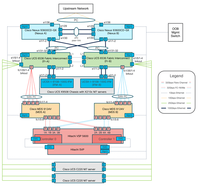
Tables listing the specifics of the connections for each component are provided below.
Table 4. Cisco Nexus 93600CD-GX A Cabling Information
| Local Device |
Local Port |
Connection |
Remote Device |
Remote Port |
| Cisco Nexus 93600CD-GX A |
1/1 |
QSFP-100G-AOC2M |
Cisco UCS 6536 FI A |
1/31 |
| 1/2 |
QSFP-100G-AOC2M |
Cisco UCS 6536 FI B |
1/31 |
|
| 1/29 |
QSFP-100G-AOC1M |
Cisco Nexus 93600CD-GX B |
1/29 |
|
| 1/30 |
QSFP-100G-AOC1M |
Cisco Nexus 93600CD-GX B |
1/30 |
|
| 1/36 |
10Gbase-SR |
Upstream Network |
|
|
| Mgmt |
Cat 5 |
Management Switch |
|
Table 5. Cisco Nexus 93600CD-GX B Cabling Information
| Local Device |
Local Port |
Connection |
Remote Device |
Remote Port |
| Cisco Nexus 93600CD-GX B |
1/1 |
QSFP-100G-AOC2M |
Cisco UCS 6536 FI A |
1/32 |
| 1/2 |
QSFP-100G-AOC2M |
Cisco UCS 6536 FI B |
1/32 |
|
| 1/29 |
QSFP-100G-AOC1M |
Cisco Nexus 93600CD-GX A |
1/29 |
|
| 1/30 |
QSFP-100G-AOC1M |
Cisco Nexus 93600CD-GX A |
1/30 |
|
| 1/36 |
10Gbase-SR |
Upstream Network |
|
|
| Mgmt |
Cat 5 |
Management Switch |
|
Table 6. Cisco UCS 6536 Fabric Interconnect A Cabling Information
| Local Device |
Local Port |
Connection |
Remote Device |
Remote Port |
| Cisco UCS 6536 FI A |
1/1 |
QSFP-40/100-SRBD |
Cisco UCS 9108-100G IFM A |
1/1 |
| 1/2 |
QSFP-40/100-SRBD |
Cisco UCS 9108-100G IFM A |
1/2 |
|
| 1/5/1 |
QSFP-4SFP25G-CU2M |
UCSC-C220-M7S-1 |
1 |
|
| 1/5/2 |
UCSC-C220-M7S-1 |
2 |
||
| 1/5/3 |
UCSC-C220-M7S-2 |
1 |
||
| 1/5/4 |
UCSC-C220-M7S-2 |
2 |
||
| 1/31 |
QSFP-100G-AOC2M |
Cisco Nexus 93600CD-GX A |
1/31 |
|
| 1/32 |
QSFP-100G-AOC2M |
Cisco Nexus 93600CD-GX A |
1/31 |
|
| 1/35/1 |
Cisco 128G FC QSP DS-SFP-4x32G-SW to MPO-LC breakout |
Cisco MDS 9124V A |
1/1 |
|
| 1/35/2 |
Cisco MDS 9124V A |
1/2 |
||
| 1/35/3 |
Cisco MDS 9124V A |
1/3 |
||
| 1/35/4 |
Cisco MDS 9124V A |
1/4 |
||
| L1 |
Cat 5 |
Cisco UCS 6536 FI B |
L1 |
|
| L2 |
Cat 5 |
Cisco UCS 6536 FI B |
L2 |
|
| Mgmt |
Cat 5 |
Management Switch |
|
Table 7. Cisco UCS 6536 Fabric Interconnect B Cabling Information
| Local Device |
Local Port |
Connection |
Remote Device |
Remote Port |
| Cisco UCS 6536 FI B |
1/1 |
QSFP-40/100-SRBD |
Cisco UCS 9108-100G IFM B |
1/1 |
| 1/2 |
QSFP-40/100-SRBD |
Cisco UCS 9108-100G IFM B |
1/2 |
|
| 1/5/1 |
QSFP-4SFP25G-CU2M
|
UCSC-C220-M7S-1 |
3 |
|
| 1/5/2 |
UCSC-C220-M7S-1 |
4 |
||
| 1/5/3 |
UCSC-C220-M7S-2 |
3 |
||
| 1/5/4 |
UCSC-C220-M7S-2 |
4 |
||
| 1/31 |
QSFP-100G-AOC2M |
Cisco Nexus 93600CD-GX B |
1/32 |
|
| 1/32 |
QSFP-100G-AOC2M |
Cisco Nexus 93600CD-GX B |
1/32 |
|
| 1/35/1 |
Cisco 128G FC QSP DS-SFP-4x32G-SW to MPO-LC breakout
|
Cisco MDS 9124V B |
1/1 |
|
| 1/35/2 |
Cisco MDS 9124V B |
1/2 |
||
| 1/35/3 |
Cisco MDS 9124V B |
1/3 |
||
| 1/35/4 |
Cisco MDS 9124V B |
1/4 |
||
| L1 |
Cat 5 |
Cisco UCS 6536 FI A |
L1 |
|
| L2 |
Cat 5 |
Cisco UCS 6536 FI A |
L2 |
|
| Mgmt |
Cat 5 |
Management Switch |
|
Table 8. Cisco UCS 9124V A Cabling Information
| Local Device |
Local Port |
Connection |
Remote Device |
Remote Port |
| Cisco MDS 9124V A |
1/1 |
DS-SFP-FC32G-SW |
Cisco UCS 6536 FI A |
1/35/1 |
| 1/2 |
DS-SFP-FC32G-SW |
Cisco UCS 6536 FI A |
1/35/2 |
|
| 1/3 |
DS-SFP-FC32G-SW |
Cisco UCS 6536 FI A |
1/35/3 |
|
| 1/4 |
DS-SFP-FC32G-SW |
Cisco UCS 6536 FI A |
1/35/4 |
|
| 1/5 |
DS-SFP-FC32G-SW |
Hitachi VS 5600 Controller 1 |
1A |
|
| 1/6 |
DS-SFP-FC32G-SW |
Hitachi VS 5600 Controller 1 |
1B |
|
| 1/7 |
DS-SFP-FC32G-SW |
Hitachi VS 5600 Controller 2 |
2A |
|
| 1/8 |
DS-SFP-FC32G-SW |
Hitachi VS 5600 Controller 2 |
2B |
|
| Mgmt |
Cat 5 |
Management Switch |
|
Table 9. Cisco UCS 9124V B Cabling Information
| Local Device |
Local Port |
Connection |
Remote Device |
Remote Port |
| Cisco MDS 9124V B |
1/1 |
DS-SFP-FC32G-SW |
Cisco UCS 6536 FI B |
1/35/1 |
| 1/2 |
DS-SFP-FC32G-SW |
Cisco UCS 6536 FI B |
1/35/2 |
|
| 1/3 |
DS-SFP-FC32G-SW |
Cisco UCS 6536 FI B |
1/35/3 |
|
| 1/4 |
DS-SFP-FC32G-SW |
Cisco UCS 6536 FI B |
1/35/4 |
|
| 1/5 |
DS-SFP-FC32G-SW |
Hitachi VS 5600 Controller 1 |
3A |
|
| 1/6 |
DS-SFP-FC32G-SW |
Hitachi VS 5600 Controller 1 |
3B |
|
| 1/7 |
DS-SFP-FC32G-SW |
Hitachi VS 5600 Controller 2 |
4A |
|
| 1/8 |
DS-SFP-FC32G-SW |
Hitachi VS 5600 Controller 2 |
4B |
|
| Mgmt |
Cat 5 |
Management Switch |
|
Table 10. Hitachi VSP 5600 Controller 1
| Local Device |
Local Port |
Connection |
Remote Device |
Remote Port |
| Hitachi VSP 5600 Controller 1 |
1A |
DS-SFP-FC32G-SW |
Cisco UCS 9124V A |
1/5 |
| 1B |
DS-SFP-FC32G-SW |
Cisco UCS 9124V A |
1/6 |
|
| 3A |
DS-SFP-FC32G-SW |
Cisco UCS 9124V B |
1/5 |
|
| 3B |
DS-SFP-FC32G-SW |
Cisco UCS 9124V B |
1/6 |
Table 11. Hitachi VSP 5600 Controller 2
| Local Device |
Local Port |
Connection |
Remote Device |
Remote Port |
| Hitachi VSP 5600 Controller 2 |
2A |
DS-SFP-FC32G-SW |
Cisco UCS 9124V A |
1/7 |
| 2B |
DS-SFP-FC32G-SW |
Cisco UCS 9124V A |
1/8 |
|
| 4A |
DS-SFP-FC32G-SW |
Cisco UCS 9124V B |
1/7 |
|
| 4B |
DS-SFP-FC32G-SW |
Cisco UCS 9124V B |
1/8 |
Table 12. VSP Service Processor (SVP)
| Local Device |
Local Port |
Connection |
Remote Device |
Remote Port |
| VSP Service Processor (SVP) |
Public LAN |
Cat 5 |
Management Switch |
User Defined |
The cables and transceivers used in the validated environment are not prescriptive to the solution but are examples of transceivers and cable connections that are valid in the design. Visit the specific product spec sheets and the Cisco Optics-to-Device Compatibility Matrix https://tmgmatrix.cisco.com/ to identify additional supported options.
Cisco Nexus LAN Switch Configuration
This chapter contains the following:
● Cisco Nexus Switch Configuration
This chapter provides a detailed procedure for configuring the Cisco Nexus 93600CD-GX switches for use in the LAN switching of the Adaptive Solutions Virtual Server Infrastructure.
The following procedures describe how to configure the Cisco Nexus switches for use in a base Adaptive Solutions VSI environment. This procedure assumes the use of Cisco Nexus 9000 10.2(5)M.
Follow the physical connectivity guidelines for infrastructure cabling as explained in the Adaptive Solutions Cabling section.
The following procedures describe this basic configuration of the Cisco Nexus switches for use in the Adaptive Solutions VSI. This procedure assumes the use of Cisco Nexus 9000 10.2(5)M, the Cisco suggested Nexus switch release at the time of this validation.
Procedure 1. Set up Initial Configuration
To set up the initial configuration for the Cisco Nexus A switch on <nexus-A-hostname>, follow these steps from a serial console:
Step 1. Configure the switch.
Note: On initial boot, the NX-OS setup should automatically start and attempt to enter Power on Auto Provisioning.
Abort Power On Auto Provisioning [yes - continue with normal setup, skip - bypass password and basic configuration, no - continue with Power On Auto Provisioning] (yes/skip/no)[no]: yes
Disabling POAP.......Disabling POAP
poap: Rolling back, please wait... (This may take 5-15 minutes)
---- System Admin Account Setup ----
Do you want to enforce secure password standard (yes/no) [y]: Enter
Enter the password for "admin": <password>
Confirm the password for "admin": <password>
Would you like to enter the basic configuration dialog (yes/no): yes
Create another login account (yes/no) [n]: Enter
Configure read-only SNMP community string (yes/no) [n]: Enter
Configure read-write SNMP community string (yes/no) [n]: Enter
Enter the switch name: <nexus-A-hostname>
Continue with Out-of-band (mgmt0) management configuration? (yes/no) [y]: Enter
Mgmt0 IPv4 address: <nexus-A-out_of_band_mgmt0-ip>
Mgmt0 IPv4 netmask: <nexus-A-mgmt0-netmask>
Configure the default gateway? (yes/no) [y]: Enter
IPv4 address of the default gateway: <nexus-A-mgmt0-gw>
Configure advanced IP options? (yes/no) [n]: Enter
Enable the telnet service? (yes/no) [n]: Enter
Enable the ssh service? (yes/no) [y]: Enter
Type of ssh key you would like to generate (dsa/rsa) [rsa]: Enter
Number of rsa key bits <1024-2048> [1024]: Enter
Configure the ntp server? (yes/no) [n]: Enter
Configure default interface layer (L3/L2) [L2]: Enter
Configure default switchport interface state (shut/noshut) [noshut]: shut
Enter basic FC configurations (yes/no) [n]: n
Configure CoPP system profile (strict/moderate/lenient/dense) [strict]: Enter
Would you like to edit the configuration? (yes/no) [n]: Enter
Step 2. Review the configuration summary before enabling the configuration.
Use this configuration and save it? (yes/no) [y]: Enter
Step 3. To set up the initial configuration of the Cisco Nexus B switch, repeat steps 1 and 2 with the appropriate host and IP address information.
Cisco Nexus Switch Configuration
To manually configure the Nexus switches, follow these steps:
Procedure 1. Enable Nexus Features
Cisco Nexus A and Cisco Nexus B (steps should be performed on both switches)
Step 1. Log in as admin using ssh.
Step 2. Run the following commands to enable Nexus features:
config t
feature nxapi
feature hsrp
feature udld
feature interface-vlan
feature lacp
feature vpc
feature lldp
Procedure 2. Set Global Configurations
Cisco Nexus A and Cisco Nexus B (steps should be performed on both switches)
Step 1. Run the following commands to set global configurations:
spanning-tree port type network default
spanning-tree port type edge bpduguard default
spanning-tree port type edge bpdufilter default
port-channel load-balance src-dst l4port
ip name-server <dns-server-1> <dns-server-2>
ip domain-name <dns-domain-name>
ip domain-lookup
ntp server <global-ntp-server-ip> use-vrf management
ntp master 3
(For Example: clock timezone EST -5 0)
clock summer-time <timezone> <start-week> <start-day> <start-month> <start-time> <end-week> <end-day> <end-month> <end-time> <offset-minutes>
(For Example: clock summer-time EDT 2 Sunday March 02:00 1 Sunday November 02:00 60)
copy run start
ip route 0.0.0.0/0 <oob-mgmt-vlan-gateway>
Note: For more information on configuring the timezone and daylight savings time or summer time, see Cisco Nexus 9000 Series NX-OS Fundamentals Configuration Guide, Release 10.2(x).
Cisco Nexus A and Cisco Nexus B (steps should be performed on both switches)
Step 1. From the global configuration mode, run the following commands:
vlan <ib-mgmt-vlan-id for example, 19>
name ib-mgmt
vlan <native-vlan-id for example, 2>
name native-vlan
vlan <vmotion-vlan-id for example, 1000>
name vmotion
vlan <vm-traffic-vlan-id for example, 1100>
name vm-traffic
vlan <vm-traffic-a-vlan-id for example, 1101>
name vm-traffic-a
vlan <vm-traffic-b-vlan-id for example, 1102>
name vm-traffic-b
Procedure 4. Add NTP Distribution Interface in IB-MGMT Subnet (Optional)
This procedure will configure each IB-MGMT SVI to be available for redistribution of the NTP service to optionally configured application networks that might not be set up to reach an upstream NTP source.
Cisco Nexus A
Step 1. From the global configuration mode, run the following commands:
interface Vlan<ib-mgmt-vlan-id>
ip address <switch-a-ntp-ip>/<ib-mgmt-vlan-netmask-length>
no shutdown
exit
ntp peer <nexus-B-mgmt0-ip> use-vrf management
Cisco Nexus B
Step 1. From the global configuration mode, run the following commands:
interface Vlan<ib-mgmt-vlan-id>
ip address <switch-b-ntp-ip>/<ib-mgmt-vlan-netmask-length>
no shutdown
exit
ntp peer <nexus-A-mgmt0-ip> use-vrf management
Procedure 5. Create Application Network Interfaces (Optional)
This procedure creates Switched Virtual Interfaces (SVI) and Hot Standby Router Protocol (HSRP) configurations for each of these SVIs. The HSRP relationship allows an active/standby relationship between the two Nexus switches for these interfaces. The IB-Mgmt network is implemented for routing upstream of the Nexus switches, and these application networks could similarly be handled.
Cisco Nexus A
int vlan 1100
no shutdown
ip address <<var_nexus_A_App-1100>>/24
hsrp 100
preempt
ip <<var_nexus_App-1100_vip>>
Note: When HSRP priority is not set, it defaults to 100. Alternating SVIs within a switch are set to a number higher than 105 to set those SVIs to default to be the standby router for that network. Be careful when the VLAN SVI for one switch is set without a priority (defaulting to 100), the partner switch is set to a priority with a value other than 100.
int vlan 1101
no shutdown
ip address <<var_nexus_A_App-1101>>/24
hsrp 101
preempt
priority 105
ip <<var_nexus_App-1101_vip>>
int vlan 1102
no shutdown
ip address <<var_nexus_A_App-1102>>/24
hsrp 102
preempt
ip <<var_nexus_App-1102_vip>>
Cisco Nexus B
int vlan 1100
no shutdown
ip address <<var_nexus_B_App-1100>>/24
hsrp 100
preempt
priority 105
ip <<var_nexus_App-1100_vip>>
int vlan 1101
no shutdown
ip address <<var_nexus_B_App-1101>>/24
hsrp 101
preempt
ip <<var_nexus_App-1101_vip>>
int vlan 1102
no shutdown
ip address <<var_nexus_B_App-1102>>/24
hsrp 102
preempt
priority 105
ip <<var_nexus_App-1102_vip>>
Procedure 6. Create Port Channels
Cisco Nexus A
Note: For fibre optic connections to Cisco UCS systems (AOC or SFP-based), entering udld enable will result in a message stating that this command is not applicable to fiber ports. This message is expected. This command will enable UDLD on twinax connections.
Step 1. From the global configuration mode, run the following commands:
interface Po10
description vPC peer-link
!
interface Eth1/29
description <nexus-b-hostname>:Eth1/29
!
interface Eth1/30
description <nexus-b-hostname>:Eth1/30
!
interface Eth1/29-30
channel-group 10 mode active
no shutdown
!
! UCS Connectivity
!
interface Po11
description <ucs-domainname>-a
!
interface Eth1/1
udld enable
description <ucs-domainname>-a:Eth1/35
channel-group 11 mode active
no shutdown
!
interface Po12
description <ucs-domainname>-b
!
interface Eth1/2
udld enable
description <ucs-domainname>-b:Eth1/35
channel-group 12 mode active
no shutdown
!
! Uplink Switch Connectivity
!
interface Po136
description MGMT-Uplink
!
interface Eth1/36
description <mgmt-uplink-switch-a-hostname>:<port>
channel-group 136 mode active
no shutdown
exit
copy run start
Cisco Nexus B
Note: For fibre optic connections to Cisco UCS systems (AOC or SFP-based), entering udld enable will result in a message stating that this command is not applicable to fiber ports. This message is expected. This command will enable UDLD on twinax copper connections.
Step 1. From the global configuration mode, run the following commands:
interface Po10
description vPC peer-link
!
interface Eth1/29
description <nexus-a-hostname>:Eth1/29
!
interface Eth1/30
description <nexus-a-hostname>:Eth1/30
!
interface Eth1/29-30
channel-group 10 mode active
no shutdown
!
! UCS Connectivity
!
interface Po11
description <ucs-domainname>-a
!
interface Eth1/1
udld enable
description <ucs-domainname>-a:Eth1/36
channel-group 11 mode active
no shutdown
!
interface Po12
description <ucs-domainname>-b
!
interface Eth1/2
udld enable
description <ucs-domainname>-b:Eth1/36
channel-group 12 mode active
no shutdown
!
! Uplink Switch Connectivity
!
interface Po136
description MGMT-Uplink
!
interface Eth1/36
description <mgmt-uplink-switch-a-hostname>:<port>
channel-group 136 mode active
no shutdown
exit
copy run start
Procedure 7. Configure Port Channel Parameters
Cisco Nexus A and Cisco Nexus B (steps should be performed on both switches)
Note: To configure port channel parameters, follow this step on both switches.
Step 1. From the global configuration mode, run the following commands to set up the VPC Peer-Link port-channel:
interface Po10
switchport mode trunk
switchport trunk native vlan <native-vlan-id>
switchport trunk allowed vlan <ib-mgmt-vlan-id>,<vmotion-vlan-id>,<vm-traffic-vlan-id>,<vm-traffic-a-vlan-id>,<vm-traffic-b-vlan-id>
spanning-tree port type network
speed 100000
duplex full
Step 2. From the global configuration mode, run the following commands to set up port-channels for UCS FI 6536 connectivity:
interface Po11
switchport mode trunk
switchport trunk native vlan <native-vlan-id>
switchport trunk allowed vlan <ib-mgmt-vlan-id>,<vmotion-vlan-id>,<vm-traffic-vlan-id>,<vm-traffic-a-vlan-id>,<vm-traffic-b-vlan-id>
spanning-tree port type edge trunk
mtu 9216
!
interface Po12
switchport mode trunk
switchport trunk native vlan <native-vlan-id>
switchport trunk allowed vlan <ib-mgmt-vlan-id>,<vmotion-vlan-id>,<vm-traffic-vlan-id>,<vm-traffic-a-vlan-id>,<vm-traffic-b-vlan-id>
spanning-tree port type edge trunk
mtu 9216
Step 3. From the global configuration mode, run the following commands to setup port-channels for connectivity to existing management switch(es):
interface Po136
switchport mode trunk
switchport trunk native vlan <native-vlan-id>
switchport trunk allowed vlan <ib-mgmt-vlan-id>
spanning-tree port type network
mtu 9216
!
exit
copy run start
Procedure 8. Configure Virtual Port Channels
Cisco Nexus A
Step 1. From the global configuration mode, run the following commands:
vpc domain <nexus-vpc-domain-id for example, 10>
role priority 10
peer-keepalive destination <nexus-B-mgmt0-ip> source <nexus-A-mgmt0-ip> vrf management
peer-switch
peer-gateway
auto-recovery
delay restore 150
ip arp synchronize
!
interface Po10
vpc peer-link
!
interface Po11
vpc 11
!
interface Po12
vpc 12
!
interface Po136
vpc 136
!
exit
copy run start
Cisco Nexus B
Step 1. From the global configuration mode, run the following commands:
vpc domain <nexus-vpc-domain-id for example, 10>
role priority 20
peer-keepalive destination <nexus-A-mgmt0-ip> source <nexus-B-mgmt0-ip> vrf management
peer-switch
peer-gateway
auto-recovery
delay restore 150
ip arp synchronize
!
interface Po10
vpc peer-link
!
interface Po11
vpc 11
!
interface Po12
vpc 12
!
interface Po136
vpc 136
!
exit
copy run start
Hitachi Ops Center Configuration and Initial VSP Settings
This chapter contains the following:
● Configure Hitachi Ops Center
Hitachi Ops Center VM must be deployed on Cisco UCS Management cluster and the Ops Center environment must meet minimum system requirements to support management of various storage systems and servers. For additional details on Hitachi Ops Center, go to: https://knowledge.hitachivantara.com/Documents/Management_Software/Ops_Center/Administrator/10.9.x/Getting_started/02_Hitachi_Ops_Center_Administrator_environment#r_hid_system_req
The software can be obtained from your respective Hitachi representative, alternatively for partner access software can be downloaded here: https://support.hitachivantara.com/en/user/answers/downloads.htm
For additional information, see the Hitachi Ops Center document library: https://knowledge.hitachivantara.com/Documents/Management_Software/Ops_Center/10.9.x/Ops_Center_10.9.x_Documentation_Library
Procedure 1. Initial Configuration of the Hitachi Ops Center
Proceed with the following steps to configure the Hitachi Ops Center after deploying the OVA template:
Step 1. Log in with the following credentials:
Username: root
Password: manager
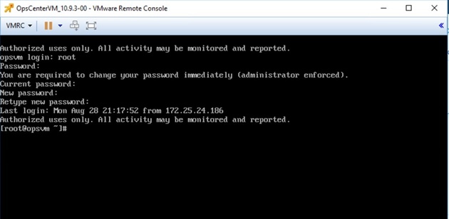
Step 2. Run the opsvmsetup command to start the setup tool.
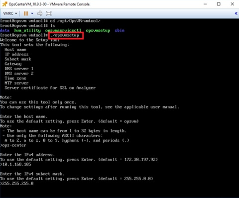
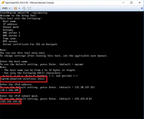
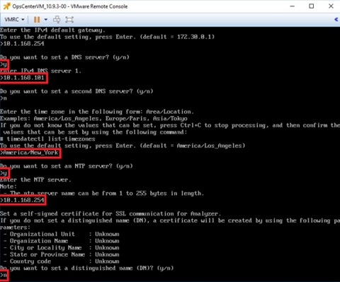
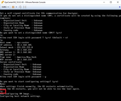
Step 3. Enter the Hostname (FQDN), IP Address, Subnet mask, Gateway, DNS, Time zone, and NTP details, as shown in the following figures.
Step 4. After providing the initial setup information, enter “y” to start the configuration.
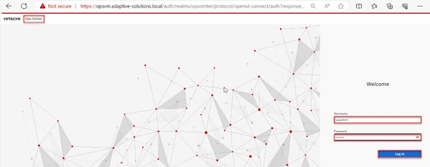
Procedure 2. Access Hitachi Ops Center Administrator
Step 1. Enter the following credentials and click Log in:
Username: sysadmin
Password: sysadmin
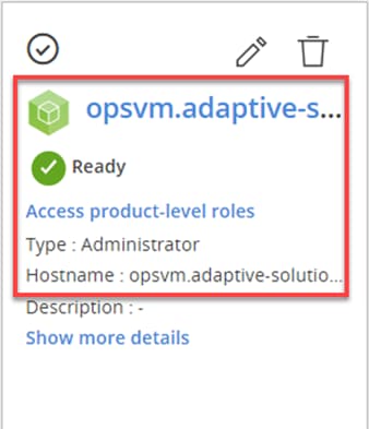
Step 2. After logging into the Hitachi Ops Center UI, you will find different product types such as Administrator, Analyzer, Analyzer detail view, Automator, and Protector.
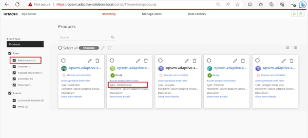
Step 3. Select the highlighted icon to launch Ops Center Administrator.
Procedure 3. Onboarding Hitachi Virtual Storage Platform to Ops Center Administrator
Onboarding a storage system is the process of associating it with Ops Center Administrator. After onboarding the storage system, you can manage it from the Ops Center Administrator dashboard.
Before you begin, verify the following:
● The service processor (SVP) username used to onboard a storage system in Ops Center Administrator has access to all resource groups on the storage system, including custom resource groups and meta resource groups, to ensure workflows function correctly.
● The user is a member of the Administration Users Group.
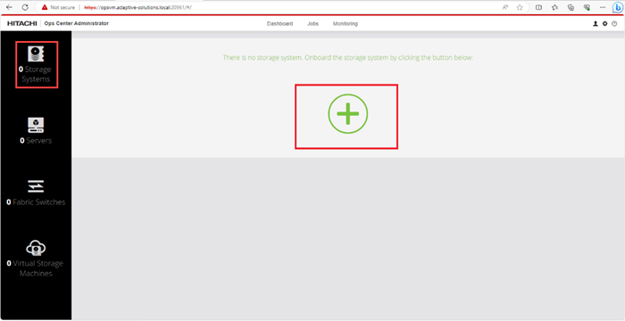
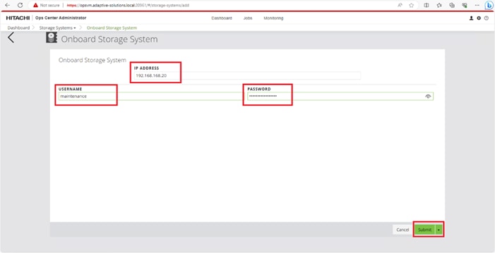
Step 1. On the Ops Center Administrator dashboard, click Storage Systems, and click the plus sign (+) to add a storage system.
Step 2. In the Onboard Storage System window, enter values for the following parameters:
● IP Address:
For a storage system with an SVP, enter the IP address (IPv4) of the SVP for the storage system you want to discover.
Note: For the VSP E1090, if there is no SVP, you can onboard storage using the IP address of the controllers.
● Username and password:
Onboard the VSP system as a user with administrator privileges on the storage system. For example, you can use the following username and password:
◦ Username: maintenance
◦ Password: raid-maintenance
Step 3. Click Submit.
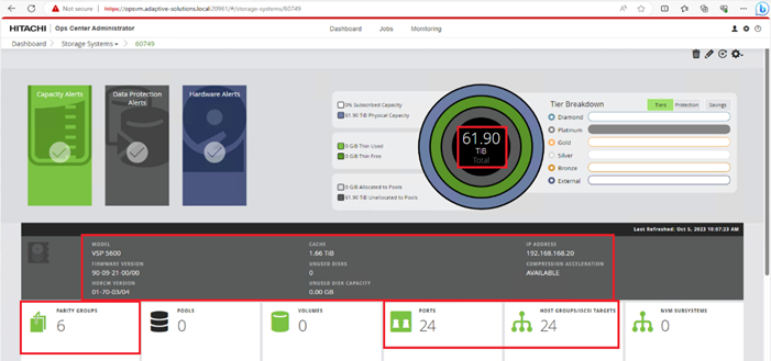
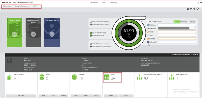
Step 4. The dashboard now shows that the number of storage systems has been increased by one. Additionally, when you click Storage Systems, you are redirected to the storage system inventory window where you can see the newly-added storage system.
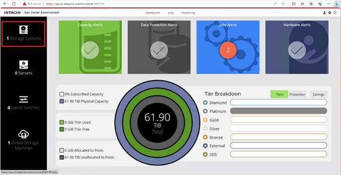
When a storage system is onboarded, the Ops Center Administrator undergoes an initialization process to gather information about the current configuration of the storage system. During this time, you may observe that the ports, volumes, pools, and Parity Groups in the storage system are "Not accessible." After the initialization is completed, you can view information about PARITY GROUPS, POOLS, VOLUMES, PORTS, HOST GROUPS/SCSI TARGETS, and NEW SUBSYSTEMS in the Storage System tab.
Procedure 4. Configure Fibre Channel Ports on the Hitachi Virtual Storage Platform from Ops Center Administrator (FC-SCSI)
Before the Ops Center Administrator can create a host storage domain (HSD) on a port, you must change the port security and port attributes settings.
Port security must be enabled for fibre ports. By default, security is disabled on the VSP storage ports. Additionally, for VSP 5000 series systems, you must verify that the port attribute is set to TARGET.
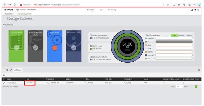
Step 1. Log in to Hitachi Ops Center Administrator. From the navigation pane, click Storage Systems.
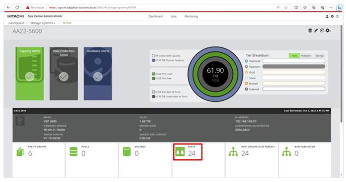
Step 2. Click the S/N listing of the Storage System.

Step 3. Click PORTS to see the configured storage ports for the storage systems.
Step 4. To modify ports, select one or more Fibre Channel ports, and then click the edit pencil icon in the Actions pane.
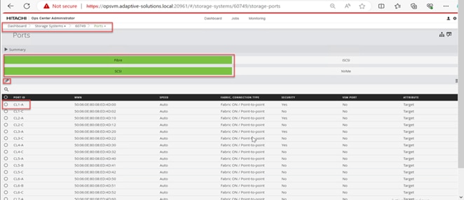
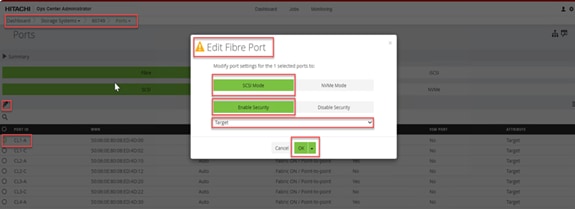
Step 5. In the Edit Fibre Port dialog box, you can change the security settings and port attributes. Verify that port settings for fibre ports used in FC-SCSI connectivity have SCSI Mode, Enable Security, and Target selected as the port attribute. In the context of this document, these settings apply to fibre ports CL1-A, CL2-A, CL3-A, and CL4-A.
Step 6. Click OK.
Cisco Intersight Managed Mode Configuration
This chapter contains the following:
● Cisco UCS Domain Configuration
● Configure Server Profile Template
● Cisco UCS IMM Setup Completion
The Cisco Intersight platform is a management solution delivered as a service with embedded analytics for Cisco and third-party IT infrastructures. The Cisco Intersight managed mode (also referred to as Cisco IMM) is a new architecture that manages Cisco Unified Computing System (Cisco UCS) fabric interconnect–attached systems through a Redfish-based standard model. Cisco Intersight managed mode standardizes both policy and operation management for the Cisco UCS X210c M7 compute nodes used in this deployment guide.
Cisco UCS C-Series M7 servers, connected and managed through Cisco UCS FIs, are also supported by IMM. For a complete list of supported platforms, go to: https://www.cisco.com/c/en/us/td/docs/unified_computing/Intersight/b_Intersight_Managed_Mode_Configuration_Guide/b_intersight_managed_mode_guide_chapter_01010.html
Procedure 1. Set Up Cisco Intersight Account
When setting up a new Cisco Intersight account (as explained in this document), the account must be enabled for Cisco Smart Software Licensing. Skip this step if starting out with a trial, or if a token has already been generated.
Step 1. Log into the Cisco Smart Licensing portal: https://software.cisco.com/software/smart-licensing/alerts.
Step 2. Verify that the correct virtual account is selected.
Step 3. Under Inventory > General, generate a new token for product registration.
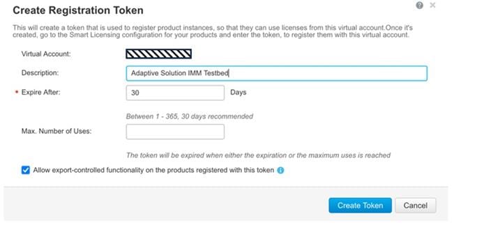
Step 4. Copy this newly created token.
Procedure 2. Set Up Cisco Intersight Licensing
Step 1. Go to https://intersight.com and click Create an account if not using an existing account.
Step 2. Select the appropriate region for the account. Click Next.
Step 3. Read and accept the license agreement. Click Next.
Step 4. Provide an Account Name. Click Create.
Step 5. Select to either Register Smart Licensing if that has been established or Start Trial.
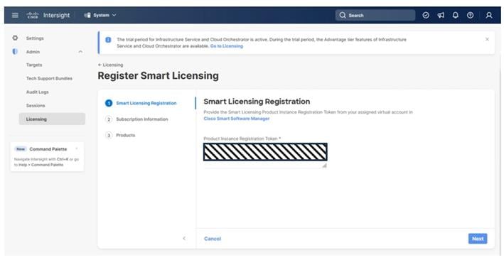
Step 6. If registering, the Register Smart Licensing will take you to System > Admin > Licensing.
Step 7. Provide the copied token from the Cisco Smart Licensing Portal. Click Next.
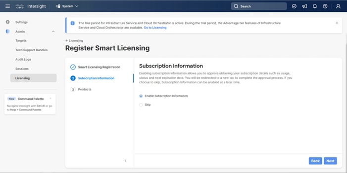
Step 8. Select Enable or Skip subscription information and click Next.
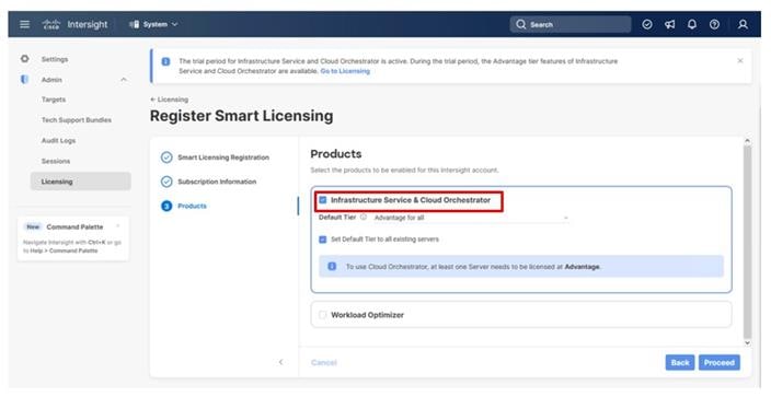
Step 9. Select the Infrastructure Service & Cloud Orchestrator option, adjust the default tier for licensing if needed, and if this should be used for existing servers, click Proceed. Click Confirm when asked to verify options.
On successfully syncing of Smart Licensing, the following page will be displayed:
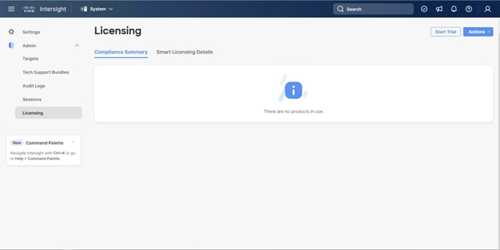
On successful creation of the Intersight account with trial licensing, the following page will be displayed:
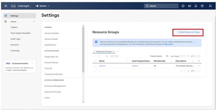
Procedure 3. Configure Cisco Intersight Resource Group
In this procedure, a Cisco Intersight resource group is created where resources such as targets will be logically grouped. In this deployment, a single resource group is created to host all the resources, but you can choose to create multiple resource groups for granular control of the resources.
Step 1. Log in to Cisco Intersight.
Step 2. At the top, select System. On the left, click Settings (the gear icon).
Step 3. Click Resource Groups in the middle panel.
Step 4. Click + Create Resource Group in the top-right corner.
Step 5. Provide a name for the Resource Group (for example, AA21-rg).
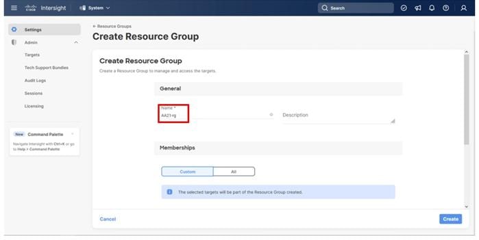
Step 6. Click Create.
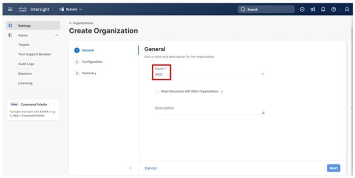
Procedure 4. Configure Cisco Intersight Organization
This procedure creates an Intersight organization where all Cisco Intersight managed mode configurations including policies are defined. To create a new organization, follow these steps:
Step 1. Log in to the Cisco Intersight portal.
Step 2. At the top, select System. On the left, click Settings (the gear icon).
Step 3. Click Organizations in the middle panel.
Step 4. Click + Create Organization in the top-right corner.
Step 5. Provide a name for the organization (for example, AA21) and click Next.
Step 6. Select the Resource Group created in the last step (for example, AA21-rg) and click Next.
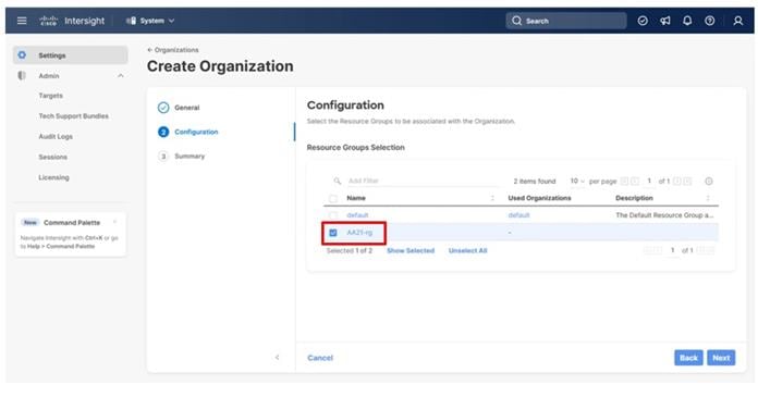
Step 7. Review the Summary and click Create.
The UCS domain contained within the Fabric Interconnects will be added directly to the account as targets. The other infrastructure components will be onboarded as targets through the Intersight Assist Appliance after it has been deployed, covered later in the Management section.
Procedure 1. Set Up Cisco Intersight Managed Mode on Cisco UCS Fabric Interconnects
The Cisco UCS fabric interconnects must be set up to support Cisco Intersight managed mode. When converting an existing pair of Cisco UCS fabric interconnects from Cisco UCS Manager mode to Intersight Managed Mode (IMM), first erase the configuration and reboot your system.
Converting fabric interconnects to Cisco Intersight managed mode is a disruptive process, and configuration information will be lost. You are encouraged to make a backup of you existing configuration. If a software version that supports Intersight Managed Mode (4.1(3) or later) is already installed on Cisco UCS Fabric Interconnects, do not upgrade the software to a recommended recent release using Cisco UCS Manager. The software upgrade will be performed using Cisco Intersight to make sure Cisco UCS X-series firmware is part of the software upgrade.
Step 1. Configure Fabric Interconnect A (FI-A) by connecting to the FI-A console. On the Basic System Configuration Dialog screen, set the management mode to Intersight.
Cisco UCS Fabric Interconnect A
Enter the configuration method. (console/gui) ? console
The Fabric interconnect will be configured in the intersight managed mode. Choose (y/n) to proceed: y
Enforce strong password? (y/n) [y]: Enter
Enter the password for "admin": <password>
Confirm the password for "admin": <password>
Enter the switch fabric (A/B) []: A
Enter the system name: <ucs-cluster-name>
Physical Switch Mgmt0 IP address : <ucsa-mgmt-ip>
Physical Switch Mgmt0 IPv4 netmask : <ucs-mgmt-mask>
IPv4 address of the default gateway : <ucs-mgmt-gateway>
DNS IP address : <dns-server-1-ip>
Configure the default domain name? (yes/no) [n]: n <optional>
Following configurations will be applied:
Management Mode=intersight
Switch Fabric=A
System Name=<ucs-cluster-name>
Enforced Strong Password=yes
Physical Switch Mgmt0 IP Address=<ucsa-mgmt-ip>
Physical Switch Mgmt0 IP Netmask=<ucs-mgmt-mask>
Default Gateway=<ucs-mgmt-gateway>
DNS Server=<dns-server-1-ip>
Apply and save the configuration (select 'no' if you want to re-enter)? (yes/no): yes
Step 2. After applying the settings, make sure you can ping the fabric interconnect management IP address. When Fabric Interconnect A is correctly set up and is available, Fabric Interconnect B will automatically discover Fabric Interconnect A during its setup process as shown in the next step.
Step 3. Configure Fabric Interconnect B (FI-B). For the configuration method, choose console. Fabric Interconnect B will detect the presence of Fabric Interconnect A and will prompt you to enter the admin password for Fabric Interconnect A. Provide the management IP address for Fabric Interconnect B and apply the configuration.
Cisco UCS Fabric Interconnect B
Enter the configuration method. (console/gui) ? console
Installer has detected the presence of a peer Fabric interconnect. This Fabric interconnect will be added to the cluster. Continue (y/n) ? y
Enter the admin password of the peer Fabric interconnect: <password>
Connecting to peer Fabric interconnect... done
Retrieving config from peer Fabric interconnect... done
Peer Fabric interconnect management mode : intersight
Peer Fabric interconnect Mgmt0 IPv4 Address: <ucsa-mgmt-ip>
Peer Fabric interconnect Mgmt0 IPv4 Netmask: <ucs-mgmt-mask>
Peer FI is IPv4 Cluster enabled. Please Provide Local Fabric Interconnect Mgmt0 IPv4 Address
Physical Switch Mgmt0 IP address : <ucsb-mgmt-ip>
Local fabric interconnect model(UCS-FI-6536)
Peer fabric interconnect is compatible with the local fabric interconnect. Continuing with the installer...
Apply and save the configuration (select 'no' if you want to re-enter)? (yes/no): yes
Procedure 2. Claim Cisco UCS Fabric Interconnects in Cisco Intersight
Note: With the initial Basic System Configuration Dialog previously completed for the fabric interconnects, log into the Fabric Interconnect A Device Console using a web browser to capture the Cisco Intersight connectivity information.
Step 1. Use the management IP address of Fabric Interconnect A to access the device from a web browser and the previously configured admin password to log into the device.
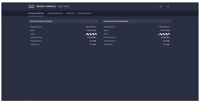
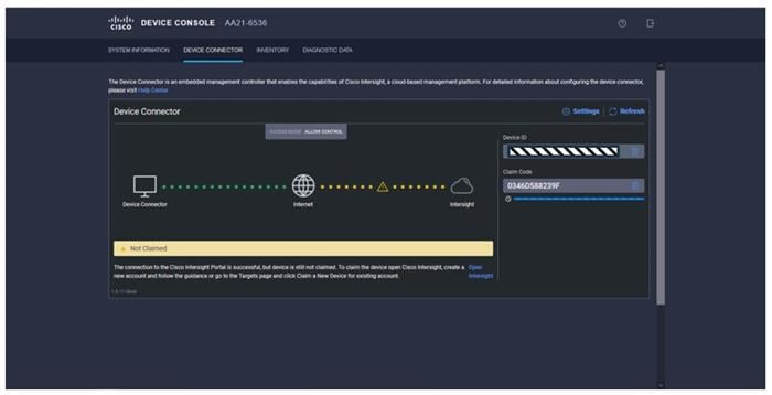
Step 2. Under DEVICE CONNECTOR, the current device status will show “Not claimed.” Note or copy the Device ID and Claim Code information for claiming the device in Cisco Intersight.
Step 3. Log in to Cisco Intersight.
Step 4. At the top, select System. On the left, click Administration > Targets.
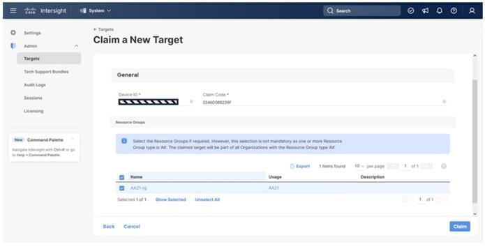
Step 5. Click Claim a New Target.
Step 6. Select Cisco UCS Domain (Intersight Managed) and click Start.
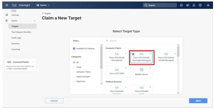
Step 7. Copy and paste the Device ID and Claim Code from the Cisco UCS FI to Intersight.
Step 8. Select the previously created resource group and click Claim.
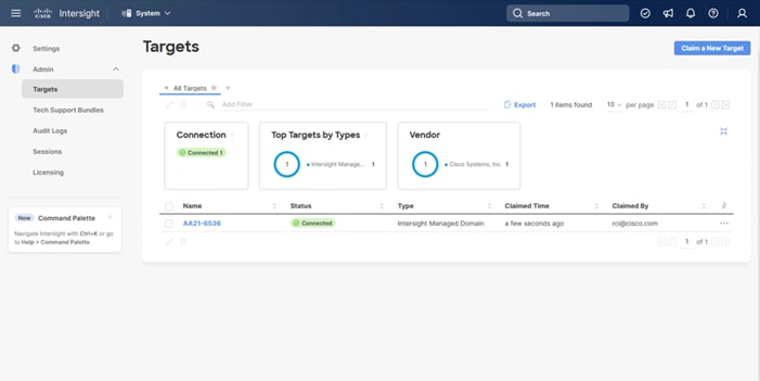
On a successful device claim, Cisco UCS FI appears as a target in Cisco Intersight:
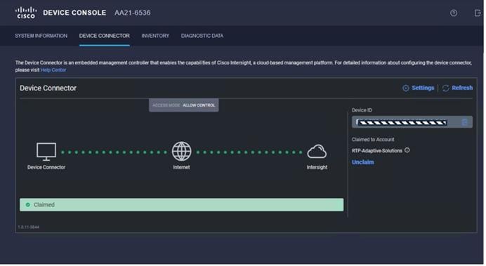
Step 9. Log in to the web GUI of the Cisco UCS fabric interconnect and click the browser refresh button.
The fabric interconnect status is now set to Claimed:
Procedure 3. Upgrade Fabric Interconnect Firmware using Cisco Intersight
Note: If your UCS 6536 Fabric Interconnects are not already running firmware release 4.3(1), upgrade will be required to support M7 servers.
Note: If Cisco UCS Fabric Interconnects were upgraded to the latest recommended software using Cisco UCS Manager, this upgrade process through Intersight will still work and will copy the X-Series firmware to the Fabric Interconnects.
Step 1. Log into the Cisco Intersight portal.
Step 2. At the top, from the drop-down list to select Infrastructure Service and then select Fabric Interconnects under Operate on the left.
Step 3. Click the ellipses “…” at the end of the row for either of the Fabric Interconnects and select Upgrade Firmware.
Step 4. Click Start.
Step 5. Verify the Fabric Interconnect information and click Next.
Step 6. Enable Advanced Mode using the toggle switch and uncheck Fabric Interconnect Traffic Evacuation.
Step 7. Select the 4.3(2) release from the list and click Next.
Step 8. Verify the information and click Upgrade to start the upgrade process.
Step 9. Watch the Request panel of the main Intersight screen as the system will ask prompt for user permission before upgrading each FI. Click on the Circle with Arrow and follow the prompts on the screen to grant permission.
Step 10. Wait for both the FIs to successfully upgrade.
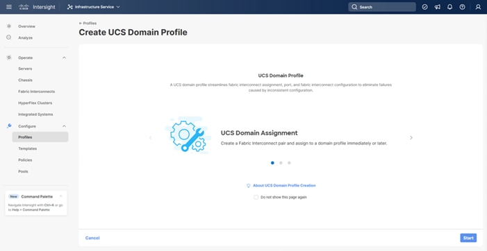
A Cisco UCS domain profile configures a fabric interconnect pair through reusable policies, allows configuration of the ports and port channels, and configures the VLANs and VSANs in the network. It defines the characteristics of and configured ports on fabric interconnects. The domain-related policies can be attached to the profile either at the time of creation or later. One Cisco UCS domain profile can be assigned to one fabric interconnect domain.
Procedure 1. Configure a Cisco UCS Domain Profile
Step 1. Log into the Cisco Intersight portal.
Step 2. At the top, from the drop-down list to select Infrastructure Service. Then, under Configure, select Profiles.
Step 3. In the main window, select UCS Domain Profiles and click Create UCS Domain Profile.
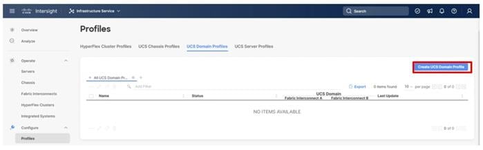
Step 4. On the Create UCS Domain Profile screen, click Start.
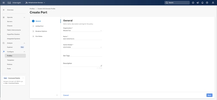
Procedure 2. UCS Domain Profile General Configuration
Step 1. Choose the organization from the drop-down list (for example, AA21).
Step 2. Provide a name for the domain profile (for example, AA21-6536-Domain-Profile).
Step 3. Provide an optional Description.
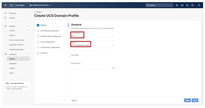
Step 4. Click Next.
Procedure 3. UCS Domain Assignment
Step 1. Assign the Cisco UCS domain to this new domain profile by clicking Assign Now and selecting the previously added Cisco UCS domain (for example, AA21-6536).
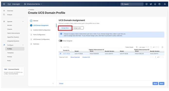
Step 2. Click Next.
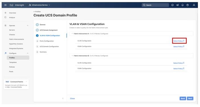
Procedure 4. VLAN and VSAN Configuration
In this procedure, a single VLAN policy is created for both fabric interconnects and two individual VSAN policies are created because the VSAN IDs are unique for each fabric interconnect that will be applied to the UCS Domain.
VLAN Configuration
Step 1. Click Select Policy next to VLAN Configuration under Fabric Interconnect A.
Step 2. In the pane on the right, click Create New.
Step 3. Verify the correct organization is selected from the drop-down list (for example, AA21) and provide a name for the policy (for example, AA21-VLAN).
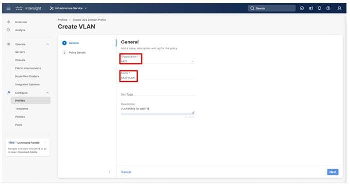
Step 4. Click Next.
Step 5. Click Add VLANs.
Step 6. Provide a name and VLAN ID for the native VLAN.
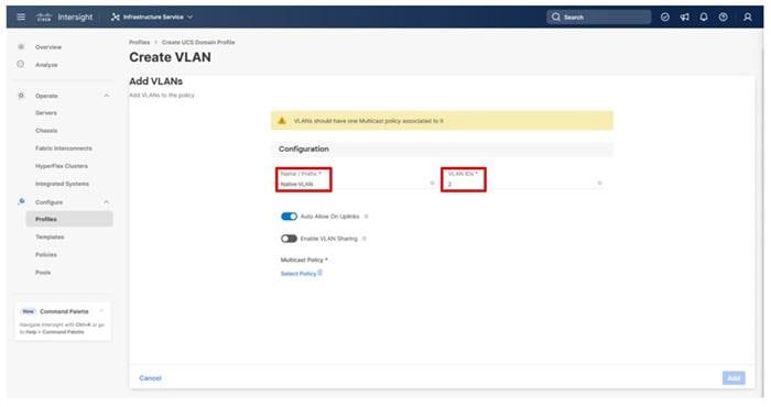
Step 7. Make sure Auto Allow On Uplinks is enabled.
Step 8. To create the required Multicast policy, click Select Policy under Multicast*.
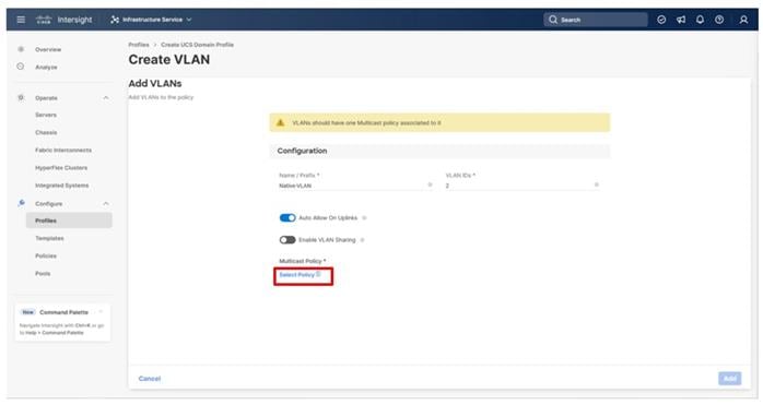
Step 9. In the window on the right, click Create New to create a new Multicast Policy.
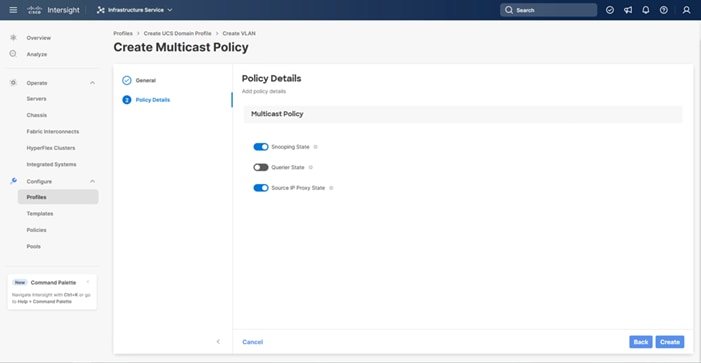
Step 10. Provide a Name for the Multicast Policy (for example, AA21-MCAST).
Step 11. Provide an optional Description and click Next.
Step 12. Leave the default settings selected and click Create.
Step 13. Click Add to add the VLAN.
Step 14. Add the remaining VLANs by clicking Add VLANs and entering the VLANs one by one. Reuse the previously created multicast policy for all the VLANs
Step 15. Select Set Native VLAN ID and enter the VLAN number (for example, 2) under VLAN ID.
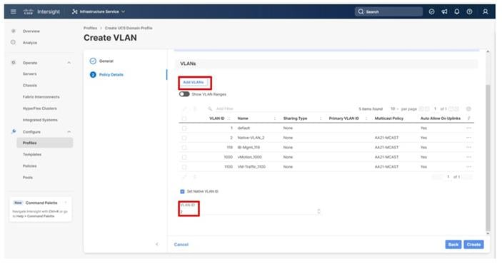
Step 16. Click Create in the bottom right to finish creating the VLAN policy and associated VLANs.
Step 17. Click Select Policy next to VLAN Configuration for Fabric Interconnect B and select the same VLAN policy.
VSAN Configuration
Step 1. Click Select Policy next to VSAN Configuration under Fabric Interconnect A. Then, in the pane on the right, click Create New.
Step 2. Verify the correct organization is selected from the drop-down list (for example, AA21) and provide a name for the policy (for example, AA21-VSAN-A).
Note: As mentioned previously, a separate VSAN-Policy is created for each fabric interconnect.
Step 3. Click Next.
Step 4. Optionally, enable Uplink Trunking.
Step 5. Click Add VSAN and provide a name (for example, VSAN-A), VSAN ID (for example, 101), and associated Fibre Channel over Ethernet (FCoE) VLAN ID (for example, 101) for SAN A.
Step 6. Set VLAN Scope as Uplink.
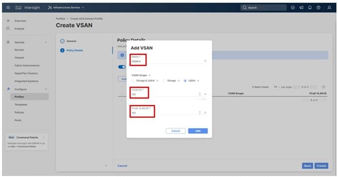
Step 7. Click Add.
Step 8. Click Create to finish creating the VSAN policy for fabric A.
Step 9. Repeat steps 1 – 8 to create a new VSAN policy for SAN-B. Name the policy to identify the SAN-B configuration (for example, AA21-VSAN- B) and use appropriate VSAN and FCoE VLAN IDs (for example, 102).
Step 10. Verify that a common VLAN policy and two unique VSAN policies are associated with the two fabric interconnects.
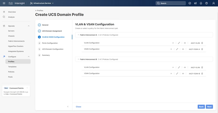
Step 11. Click Next.
Procedure 5. Ports Configuration
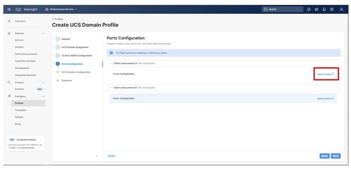
This procedure creates the Ports Configuration policies for Fabric Interconnect A, and these steps will be repeated for Fabric Interconnect B with certain specified differences. Using separate policies provides flexibility when port configuration (port numbers or speed) differs between the two FIs.
Note: Use two separate port policies for the fabric interconnects. When configuring Fibre Channel, two port policies are required because each fabric interconnect uses a unique Fibre Channel VSAN ID.
Step 1. Click Select Policy for Fabric Interconnect A.
Step 2. Click Create New in the pane on the right to define a new port configuration policy.
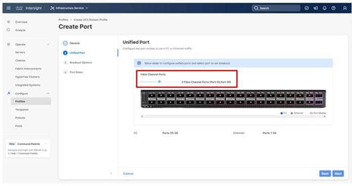
Step 3. Verify that the correct organization is selected from the drop-down list (for example, AA02) and provide a name for the policy (for example, AA21-6536-Port-A). Select the UCS-FI-6536 Switch Model.
Step 4. Click Next.
Step 5. Move the slider to set up unified ports. In this deployment, the last two ports were selected as Fibre Channel ports as 4x32G breakouts. Click Next.
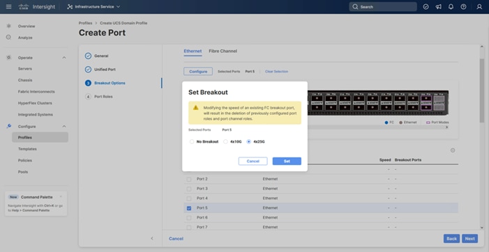
Step 6. If any Ethernet ports need to be configured as breakouts, either 4x25G or 4x10G, for connecting C-Series servers or a UCS 5108 chassis, configure them here. In the list, select the checkbox next to any ports that need to be configured as breakout or select the ports on the graphic. When all ports are selected, click Configure at the top of the window.
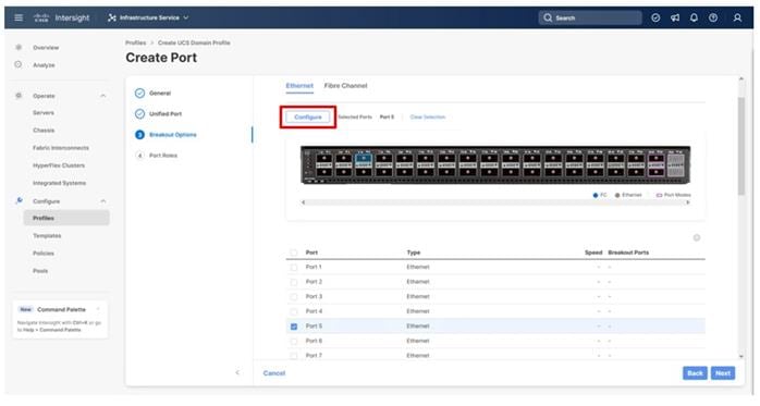
Step 7. In the Set Breakout popup, select either 4x10G or 4x25G and click Set.
Step 8. Under Breakout Options, select Fibre Channel. Select any ports that need the speed changed from 16G to 32G and click Configure.
Step 9. In the Set Breakout popup, select 4x32G and click Set.
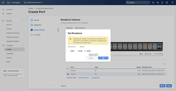
Step 10. Click Next.
Step 11. In the list, select the checkbox next to any ports that need to be configured as server ports, including ports connected to chassis or C-Series servers. Ports can also be selected on the graphic. When all ports are selected, click Configure. Breakout and non-breakout ports cannot be configured together. If you need to configure breakout and non-breakout ports, do this configuration in two steps.
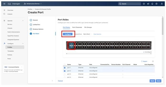
Step 12. Specify the Role of Server for the selected IFM ports.
Step 13. Click Save.
Step 14. Select any breakout ports intended for C-Series and click Configure.
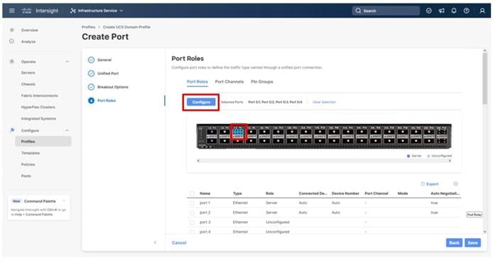
Step 15. Repeat the selection of Server for the Role and click Save.
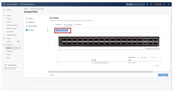
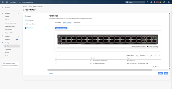
Step 16. Click the Port Channels tab under Port Roles.
Step 17. Click Create Port Channel.
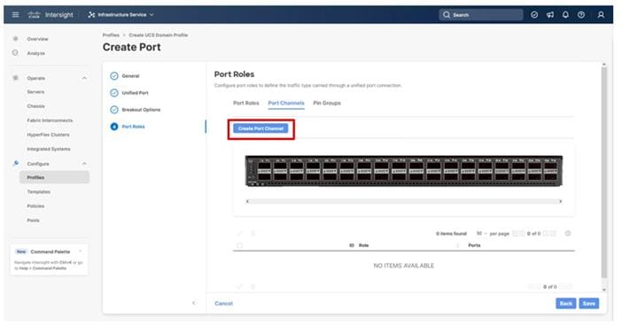
Step 18. To create the network uplinks to the Nexus 93600CD-GX switches, leave the Role as Ethernet Uplink Port selected.
Step 19. Specify a Port Channel ID (example 11). Specify an Admin Speed if the upstream ports require it, otherwise leave it as Auto.
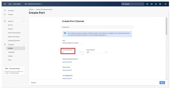
Note: Ethernet Network Group, Flow Control, and Link Aggregation policies for defining a disjoint Layer-2 domain or fine tune port-channel parameters can be configured here, but these policies were not used in this deployment and system default values were utilized.
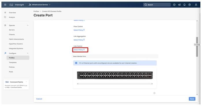
Step 20. Scroll down if Link Control and Select Member Ports is not visible within the Create Port Channel dialogue, click Select Policy under Link Control, and then select Create New in the upper area of the right-side pane.
Step 21. Provide a name for the policy (example, AA21-UDLD-Link-Control), and click Next.
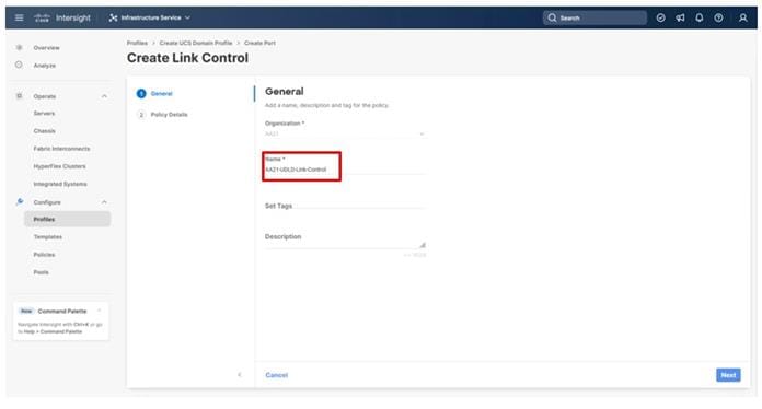
Step 22. Leave the default values selected and click Create.
Step 23. Select the ports connected to the upstream Nexus switches (example, port 31 and 32).
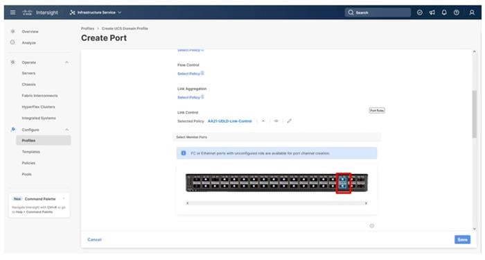
Step 24. Click Save.
Procedure 6. Configure FC Port Channel
This procedure will create the Fibre Channel Port Channel for Fabric Interconnect A, and these steps will later be repeated for Fabric Interconnect B with certain specified differences. A difference is needed for these Fibre Channel Port Channel configurations because of the use of a unique Fibre Channel VSAN ID.
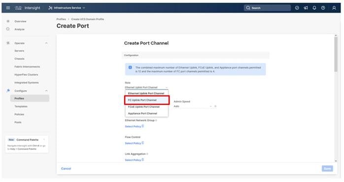
Step 1. Configure a Fibre Channel Port Channel by selecting the Port Channel in the main pane again and clicking Create Port Channel.
Step 2. In the drop-down list under Role, choose FC Uplink Port Channel.
Step 3. Provide a port-channel ID (for example, 101), select a value for Admin Speed (for example, 32Gbps), and provide a VSAN ID (for example, 101).
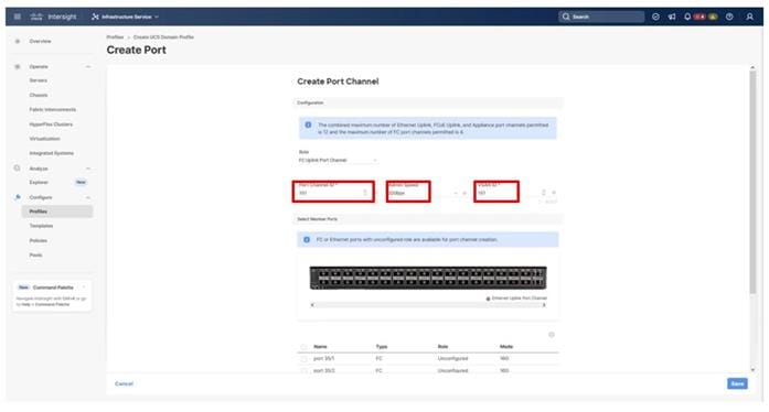
Step 4. Select ports (for example, 35/1,35/2,35/3,35/4).
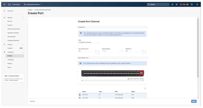
Step 5. Click Save.
Step 6. Verify the port-channel IDs and ports after both the Ethernet uplink port channel and the Fibre Channel uplink port channel have been created.
Step 7. Click Save to create the port policy for Fabric Interconnect A.
Procedure 7. Fabric Interconnect B Ports and Port Channel Configurations
Step 1. Repeat the steps in Ports Configuration and Configure FC Port Channel to create the port policy for Fabric Interconnect B including the Ethernet port-channel and the FC port-channel. Use the following values for various parameters:
◦ Name of the port policy: AA21-6536-Port-B
◦ Ethernet port-Channel ID: 12
◦ FC port-channel ID: 102
◦ FC VSAN ID: 102
Step 2. When the port configuration for both fabric interconnects is complete and looks correct, click Next.
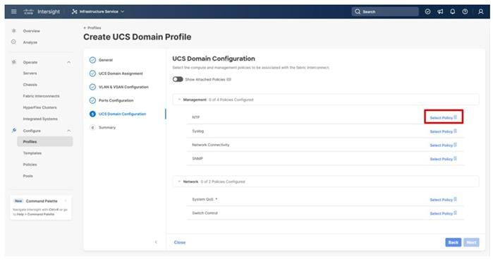
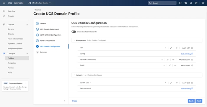
Procedure 8. UCS Domain Configuration
Under UCS domain configuration, additional policies can be configured to set up NTP, Syslog, DNS settings, SNMP, QoS and the UCS operating mode (end host or switch mode). For this deployment, four policies (NTP, Network Connectivity, SNMP, and System QoS) will be configured, as shown below:
Step 1. Click Select Policy next to NTP and in the pane on the right, click Create New.
Step 2. Verify that the correct organization is selected from the drop-down list (for example, AA21) and provide a name for the policy (for example, AA21-NTP).
Step 3. Click Next.
Step 4. Enable NTP, provide the first NTP server IP address, and select the time zone from the drop-down list.
Step 5. (Optional) Add a second NTP server by clicking + next to the first NTP server IP address.
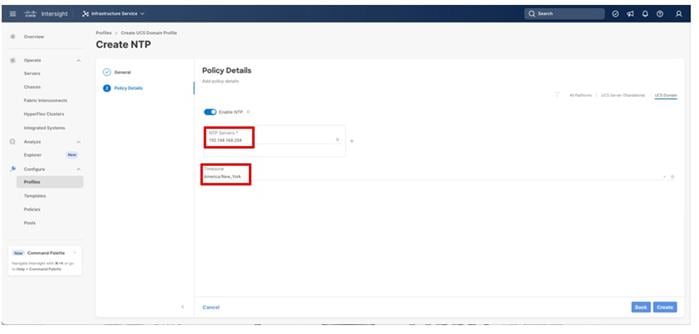
Step 6. Click Create.
Configure Network Connectivity Policy
Step 1. Click Select Policy next to Network Connectivity and in the pane on the right, click Create New.
Step 2. Verify that the correct organization is selected from the drop-down list (for example, AA21) and provide a name for the policy (for example, AA21-NetConn).
Step 3. Click Next.
Step 4. Provide the appropriate DNS server IP addresses for the Cisco UCS domain.
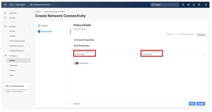
Step 5. Click Create.
Configure SNMP Policy (Optional)
Step 1. Click Select Policy next to SNMP and in the pane on the right, click Create New.
Step 2. Verify that the correct organization is selected from the drop-down list (for example, AA21) and provide a name for the policy (for example, AA21-SNMP).
Step 3. Click Next.
Step 4. Provide a System Contact email address, a System Location, and optional Community Strings.
Step 5. Under SNMP Users, click Add SNMP User.
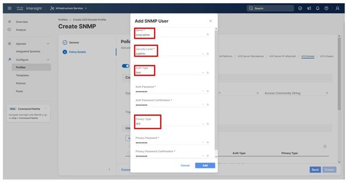
Step 6. Optionally, add an SNMP Trap Destination (for example, the NDFC IP Address). If the SNMP Trap Destination is V2, you must add a Trap Community String.
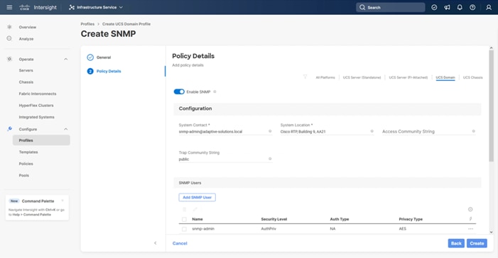
Step 7. Click Create.
Procedure 9. Configure System QoS Policy
The System QoS policy will be adjusted to expand the capacity of the Ethernet uplinks to support jumbo frames. All Ethernet traffic is set within a common class of Best Effort in this design, which will have the MTU adjusted. Different strategies can be implemented for QoS giving weighted priorities, but any such effort would need to take care to match settings implemented upstream of the fabric interconnects.
Step 1. Click Select Policy next to System QoS* and in the pane on the right, click Create New.
Step 2. Verify that the correct organization is selected from the drop-down list (for example, AA21) and provide a name for the policy (for example, AA21-QoS).
Step 3. Click Next.
Step 4. Change the MTU for Best Effort class to 9216.
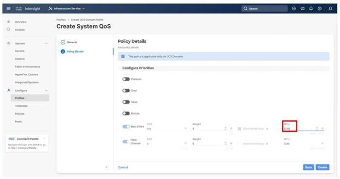
Step 5. Click Create.
Step 6. Click Next.
Procedure 10. Deploy the UCS Domain Profile
Step 1. Verify that all the settings including the fabric interconnect settings, by expanding the settings and making sure that the configuration is correct.
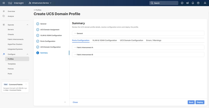
Step 2. Click Deploy.
Step 3. Acknowledge any warnings and click Deploy again.
Note: The system will take some time to validate and configure the settings on the fabric interconnects. Log into the console servers to see when the Cisco UCS fabric interconnects have finished configuration and are successfully rebooted.
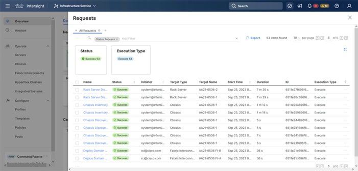
Procedure 11. Verify Cisco UCS Domain Profile Deployment
When the Cisco UCS domain profile has been successfully deployed, the Cisco UCS chassis and the blades should be successfully discovered.
Note: It takes a while to discover the blades for the first time. Watch the number of outstanding requests in Cisco Intersight:
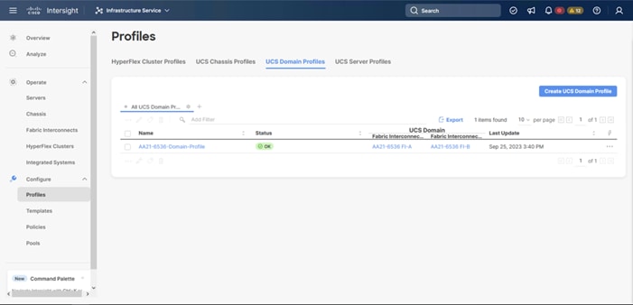
Step 1. Log in to Cisco Intersight. Go to Infrastructure Service > Configure > Profiles > UCS Domain Profiles, verify that the domain profile has been successfully deployed.
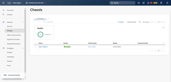
Step 2. Verify that the chassis (either UCSX-9508 or UCS 5108 chassis) has been discovered and is visible under Infrastructure Service > Operate > Chassis.
Step 3. Verify that the servers have been successfully discovered and are visible under Infrastructure Service > Operate > Servers.
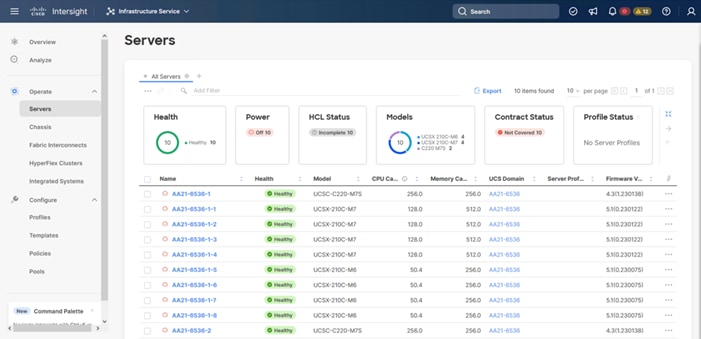
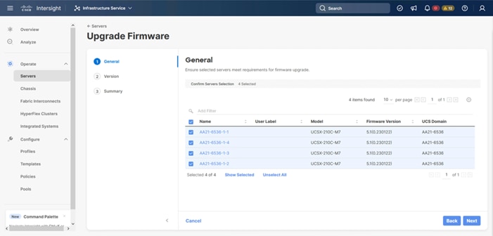
Procedure 12. Update Server Firmware
Step 1. With the servers recognized, the servers can be upgraded from the most recent Servers view in Infrastructure Service > Operate > Servers.
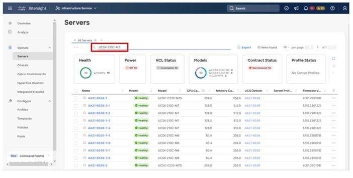
Step 2. Optionally, specify the desired model to work with from the list (example UCSX-210C-M7) and enter it within the filter box near the top.
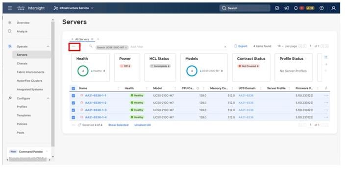
Step 3. Select all servers from the resulting list by clicking the left side box of the column header, or manually select a specific set from the results.
Step 4. Click the ellipsis (…) near the top left for the drop-down list.
Step 5. Select the Upgrade Firmware option.
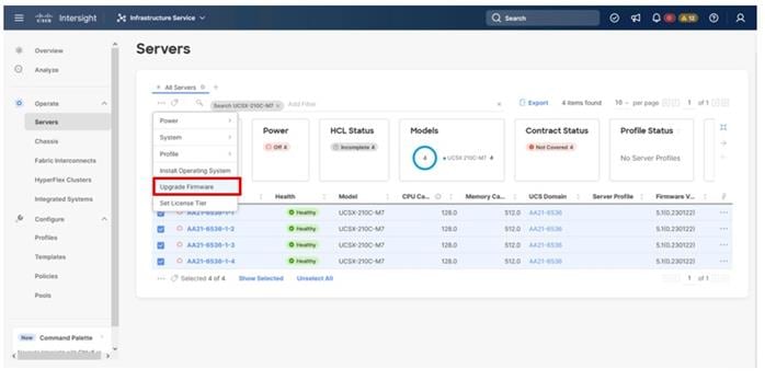
Step 6. Click Start on the resulting page and click Next after confirming that the servers to be upgraded have been selected.
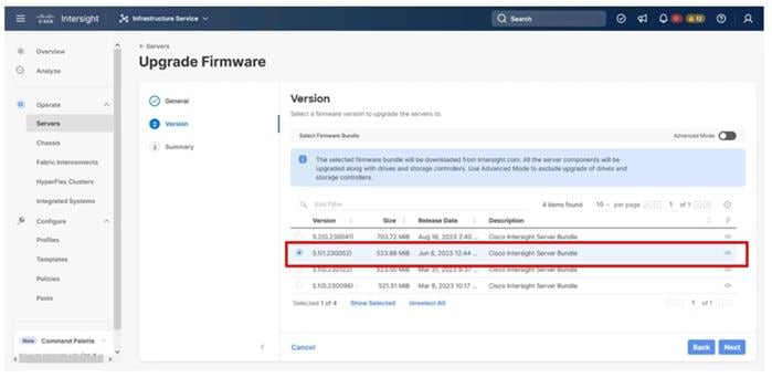
Step 7. Select the version to upgrade the servers to and click Next.
Step 8. Click Upgrade, select the toggle to Reboot Immediately to Begin Upgrade, and click Upgrade again.
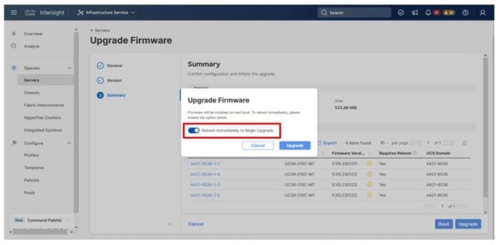
Firmware upgrade times will vary, but 30-45minutes is a safe estimate to completion.
Configure Cisco UCS Chassis Profile (Optional)
The Cisco UCS Chassis profile in Cisco Intersight allows you to configure various parameters for the chassis, including:
● IMC Access Policy: IP configuration for the in-band chassis connectivity. This setting is independent of Server IP connectivity and only applies to communication to and from the chassis.
● SNMP Policy, and SNMP trap settings.
● Power Policy to enable power management and power supply redundancy mode.
● Thermal Policy to control the speed of FANs (only applicable to Cisco UCS 5108)
A chassis policy can be assigned to any number of chassis profiles to provide a configuration baseline for a chassis. In this deployment, no chassis profile was created or attached to the chassis, but you can configure policies to configure SNMP or Power parameters and attach them to the chassis.
Configure Server Profile Template
In the Cisco Intersight platform, a server profile enables resource management by simplifying policy alignment and server configuration. The server profiles are derived from a server profile template. A server profile template and its associated policies can be created using the server profile template wizard. After creating the server profile template, you can derive multiple consistent server profiles from the template.
The server profile templates captured in this deployment guide support Cisco UCS X210c M7 compute nodes with 5th Generation VICs. Cisco UCS C-Series connections were shown during the creation of the port profile policies used for the FIs to illustrate breakout ports but are otherwise not part of this validation. In deployments, Cisco UCS C-Series profile templates can be nearly identical to configurations used for Cisco UCS X-Series or B-Series but might differ in aspects such as power policies.
vNIC and vHBA Placement for Server Profile Template
This section explains the vNIC and vHBA layout used in this deployment.
Four vNICs and four vHBAs are configured to support FC boot from SAN. The vNICs are split up into a pair uplinking to the standard vSwitch supporting the management vmkernel, and the remaining two connecting into a vSphere Distributed Switch (VDS) to carry vMotion and application traffic. Two vHBAs (FC-A and FC-B) are used for boot from SAN connectivity and the remaining two vHBAs (FC-NVMe-A and FC-NVMe-B) are used to support FC-NVMe. These devices are manually placed as listed in Table 13.
Table 13. vHBA and vNIC placement
| vNIC/vHBA Name |
Slot |
Switch ID |
PCI Order |
| 00-vSwitch0-A |
MLOM |
A |
0 |
| 01-vSwitch0-B |
MLOM |
B |
1 |
| 02-VDS0-A |
MLOM |
A |
2 |
| 03-VDS0-B |
MLOM |
B |
3 |
| FC-A |
MLOM |
A |
4 |
| FC-B |
MLOM |
B |
5 |
| FC-NVMe-A |
MLOM |
A |
6 |
| FC-NVMe-B |
MLOM |
B |
7 |
Procedure 1. Server Profile Template Creation
Step 1. Log in to Cisco Intersight.
Step 2. Go to Infrastructure Service > Configure > Templates and in the main window click Create UCS Server Profile Template.
Procedure 2. General Configuration
Step 1. Select the organization from the drop-down list (for example, AA21).
Step 2. Provide a name for the server profile template. (for example, FC-Boot-FC-NVMe-Template)
Step 3. Select UCS Server (FI-Attached).
Step 4. Provide an optional description.
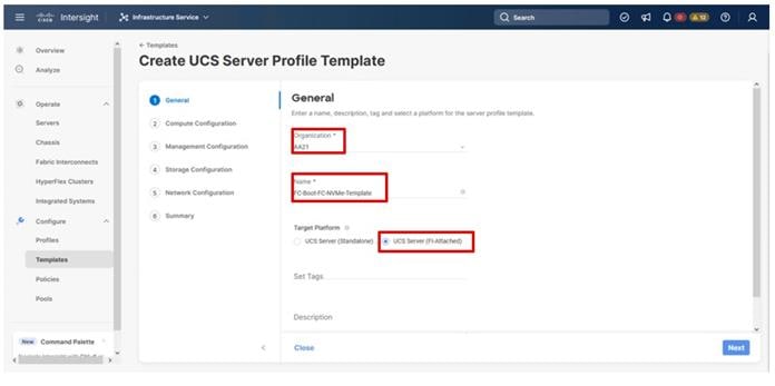
Step 5. Click Next.
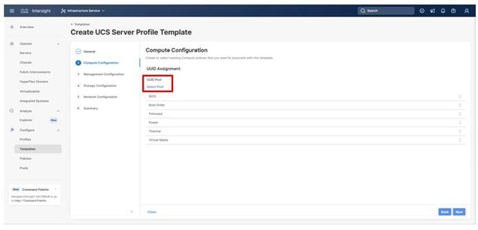
The following subcomponents of pools and policies will be addressed in the Compute Configuration:
● A UUID Pool will be created to be used for the identities of Server Profiles derived from the Server Profile Template
● A BIOS Policy to set the available settings for the underlying hardware of the UCS Compute Nodes
● A Boot Order Policy to set the boot order of the Compute Nodes
● A Virtual Media Policy to enable virtual media accessibility to the KVM
Procedure 1. Configure UUID Pool
Step 1. Click Select Pool under UUID Pool and then in the pane on the right, click Create New.
Step 2. Verify that the correct organization is selected from the drop-down list (for example, AA21) and provide a name for the UUID Pool (for example, AA21-UUID-Pool).
Step 3. Provide an optional Description and click Next.
Step 4. Provide a hexadecimal UUID Prefix (for example, a prefix of AA210000-0000-0001 was used).
Step 5. Add a UUID block specifying a From starting value and a Size.
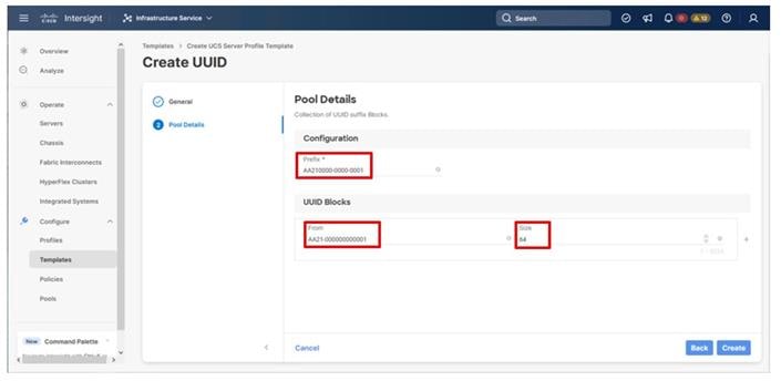
Step 6. Click Create.
Procedure 2. Configure BIOS Policy
Step 1. Click Select Policy next to BIOS and in the pane on the right, click Create New.
Step 2. Verify that the correct organization is selected from the drop-down list (for example, AA21) and provide a name for the policy (for example, AA21-Intel-M7-VSI-BIOS).
Step 3. Click Next.
Step 4. On the Policy Details screen, select the appropriate values for the BIOS settings. In this deployment, the BIOS values were selected based on recommendations in the performance tuning guide for Cisco UCS M7 BIOS: https://www.cisco.com/c/en/us/products/collateral/servers-unified-computing/ucs-b-series-blade-servers/ucs-m7-platforms-wp.html. Set the parameters below and leave all other parameters set to platform-default.
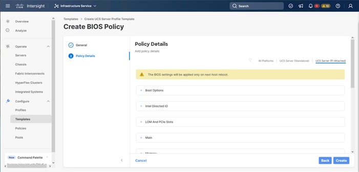
◦ Processor > Processor C6 Report: Enabled
◦ Processor > Workload configuration: Balanced
◦ Server Management > Consistent Device Naming: Enabled
Step 5. Click Create.
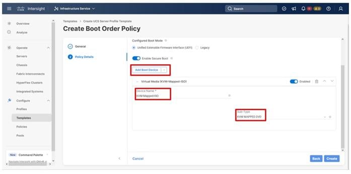
Procedure 3. Configure Boot Order Policy
Note: The FC boot order policy applies to all FC hosts including hosts that support FC-NVMe storage access.
Step 1. Click Select Policy next to Boot Order and in the pane on the right, click Create New.
Step 2. Verify that the correct organization is selected from the drop-down list (for example, AA21) and provide a name for the policy (for example, AA21-FC-Boot-Order).
Step 3. Click Next.
Step 4. For Configured Boot Mode, select Unified Extensible Firmware Interface (UEFI).
Step 5. Turn on Enable Secure Boot.
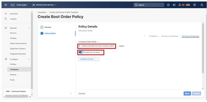
Step 6. From the Add Boot Device drop-down list, select Virtual Media.
Step 7. Provide a Device Name (for example, KVM-Mapped-ISO) and for the Sub-Type, select KVM Mapped DVD.
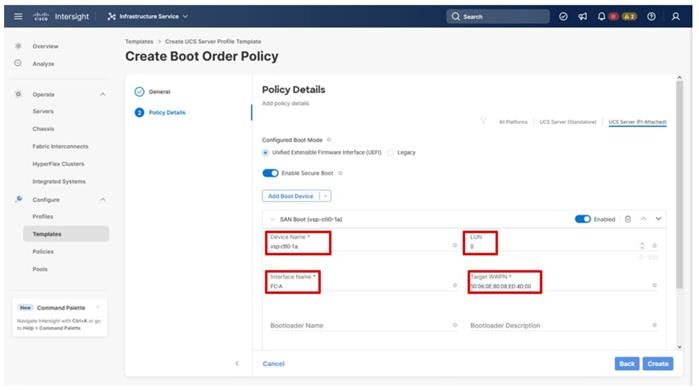
Step 8. From the Add Boot Device drop-down list, select SAN Boot.
Step 9. Provide the Device Name: vsp-ctl0-1a and the Logical Unit Number (LUN) value (for example, 0).
Step 10. Provide an interface name FC-A. This value is important and should match the vHBA name.
Step 11. Add the appropriate World Wide Port Name (WWPN) as the Target WWPN (referenced within Hitachi Ops Center as World Wide Name (WWN)).
Note: To determine these, you need to reference the Port information from within Ops Center. All four Hitachi VSP WWN will be added as boot options.
Step 12. Open Ops Center Administrator Dashboard > Storage Systems > [S/N of VSP listing]
Step 13. From the resulting view, click Ports.
Step 14. Find and add the WWN for each port connected to the MDS.
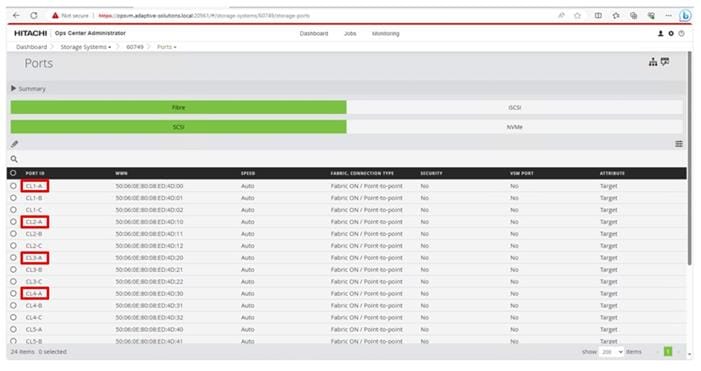
● vsp-ctl0-1a: VSP Controller 0, LIF for Fibre Channel SAN A - 50:06:0E:80:08:ED:4D:00
● vsp-ctl0-3a: VSP Controller 0, LIF for Fibre Channel SAN B - 50:06:0E:80:08:ED:4D:20
● vsp-ctl1-2a: VSP Controller 1, LIF for Fibre Channel SAN A - 50:06:0E:80:08:ED:4D:10
● vsp-ctl0-4a: VSP Controller 1, LIF for Fibre Channel SAN B - 50:06:0E:80:08:ED:4D:30
Step 15. Repeat steps 8-14 for the remaining VSP ports.
Step 16. From the Add Boot Device drop-down list, select Virtual Media.
Step 17. Add the Device Name example (CIMC-Mapped-ISO) and select the subtype CIMC MAPPED DVD.

Step 18. Verify that the order of the boot policies and adjust the boot order as necessary using arrows next to the trashcan button.
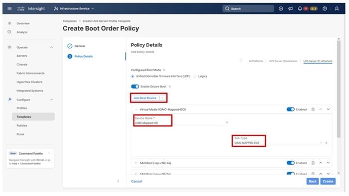
Step 19. Click Create.
Procedure 4. Configure Virtual Media Policy
Step 1. Click Select Policy next to Virtual Media and in the pane on the right, click Create New.
Step 2. Verify that the correct organization is selected from the drop-down list (for example, AA21) and provide a name for the policy (for example, AA21-KVM-Mount-Media).
Step 3. Turn on Enable Virtual Media, Enable Virtual Media Encryption, and Enable Low Power USB.
Step 4. Do not select Add Virtual Media at this time, but the policy can be modified and used to map an ISO for a CIMC Mapped DVD.
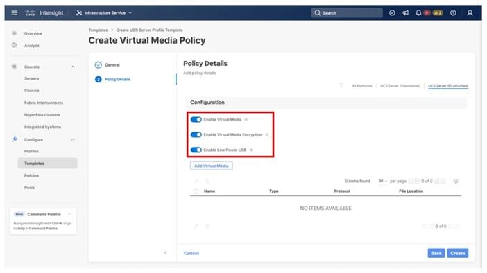
Step 5. Click Create.
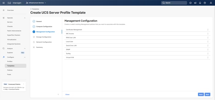
Step 6. Click Next to go to Management Configuration.
The following policies will be added to the management configuration:
● IMC Access to define the pool of IP addresses for compute node KVM access
● IPMI Over LAN to allow Intersight to manage IPMI messages
● Local User to provide local administrator to access KVM
● Virtual KVM to allow the Tunneled KVM
Procedure 5. Configure Cisco IMC Access Policy
Step 1. Click Select Policy next to IMC Access and in the pane on the right, click Create New.
Step 2. Verify that the correct organization is selected from the drop-down list (for example, AA21) and provide a name for the policy (for example, AA21-IMC-Access-Policy).
Step 3. Click Next.
Step 4. Click UCS Server (FI-Attached) if not selected.
Step 5. Select the toggle to enable Out-of-Band Configuration. Click Select IP Pool and in the pane on the right, click Create New.
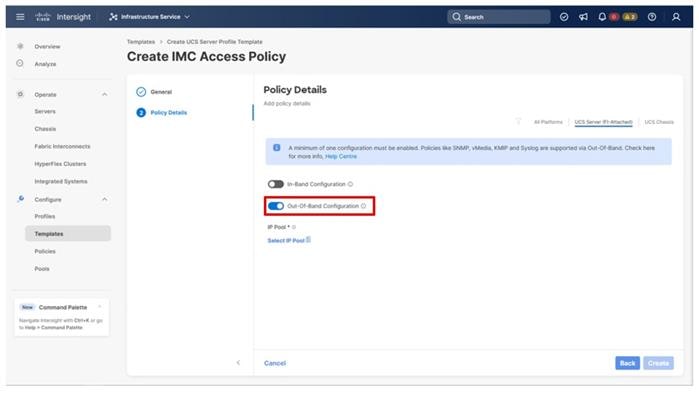
Note: This example will use the Out-Of-Band configuration that will pass through the configured management interfaces of the fabric interconnect. The In-Band configuration option will use the fabric interconnect uplinks for connectivity and must specify the VLAN for the connectivity.
Step 6. Verify that the correct organization is selected from the drop-down list (for example, AA21) and provide a name for the policy (for example, AA21-OOB-Mgmt-Pool). Click Next.
Step 7. Select Configure IPv4 Pool and provide the information to define a pool for KVM IP address assignment including an IP Block.
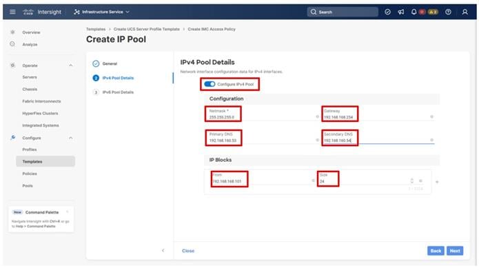
Note: For tunneled KVM to work, the management IP pool subnet should be accessible from the Fabric Interconnect management interfaces.
Step 8. Click Next.
Step 9. Deselect Configure IPv6 Pool.
Step 10. Click Create to finish configuring the IP address pool.
Step 11. Click Create to finish configuring the IMC access policy.
Procedure 6. Configure IPMI Over LAN Policy
Step 1. Click Select Policy next to IPMI Over LAN and in the pane on the right, click Create New.
Step 2. Verify that the correct organization is selected from the drop-down list (for example, AA21) and provide a name for the policy (for example, AA21-Enable-IPMIoLAN-Policy).
Step 3. Leave the default settings in place for this policy.
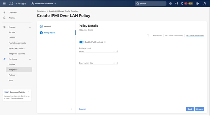
Step 4. Click Create.
Procedure 7. Configure Local User Policy
Step 1. Click Select Policy next to Local User and in the pane on the right, click Create New.
Step 2. Verify that the correct organization is selected from the drop-down list (for example, AA21) and provide a name for the policy (for example, AA21-LocalUser).
Step 3. Verify that UCS Server (FI-Attached) is selected.
Step 4. Verify that Enforce Strong Password is selected.
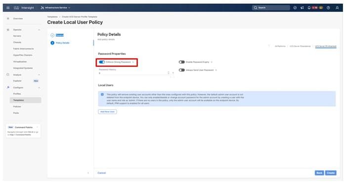
Step 5. Click Add New User and then click + next to the New User.
Step 6. Provide the username (for example, vsiuser), choose a role (for example, admin), and provide a password.
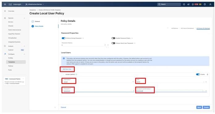
Note: The username and password combination defined here will be used as an alternate to log in to KVMs and can be used for IPMI.
Step 7. Click Create to finish configuring the user.
Step 8. Click Create to finish configuring the Local User Policy.
Procedure 8. Configure Virtual KVM Policy
Step 1. Click Select Policy next to Virtual KVM and in the pane on the right, click Create New.
Step 2. Verify that the correct organization is selected from the drop-down list (for example, AA21) and provide a name for the policy (for example, AA21-KVM-Policy).
Step 3. Verify that UCS Server (FI-Attached) is selected.
Step 4. Turn on Allow Tunneled vKVM.
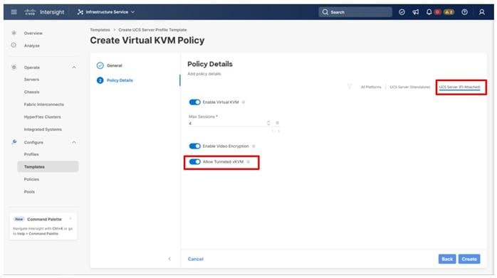
Step 5. Click Create.
Step 6. To fully enable Tunneled KVM, after the Server Profile Template has been created, go to System > Settings > Security and Privacy and click Configure. Turn on Allow Tunneled vKVM Launch and Allow Tunneled vKVM Configuration.
Step 7. Click Next to continue to Storage Configuration.
The Storage Configuration section of the Server Profile Template is not required for internal storage in the UCS servers because all storage for this solution is provided by the VSP. Click Next on the Storage Configuration screen.
Network Configuration
This section details how to create the LAN Connectivity and SAN Connectivity policies used by the derived Server Profiles.
LAN Connectivity
Procedure 1. Create Network Configuration - LAN Connectivity Policy
The LAN connectivity policy defines the connections and network communication resources between the server and the LAN. This policy uses pools to assign MAC addresses to servers and to identify the vNICs that the servers use to communicate with the network.
For consistent vNIC placement, manual vNIC placement is used. The four vNICs configured are listed in Table 14.
Table 14. vNICs defined in LAN Connectivity
| vNIC/vHBA Name |
Slot ID |
Switch ID |
PCI Order |
VLANs |
| 00-vSwitch0-A |
MLOM |
A |
0 |
IB-MGMT |
| 01-vSwitch0-B |
MLOM |
B |
1 |
IB-MGMT |
| 02-vDS0-A |
MLOM |
A |
2 |
VM Traffic, VM Traffic-A, VM Traffic-B, vMotion |
| 03-vDS0-B |
MLOM |
B |
3 |
VM Traffic, VM Traffic-A, VM Traffic-B, vMotion |
Step 1. Click Select Policy next to LAN Connectivity and in the pane on the right, click Create New from the column that appears to the right.
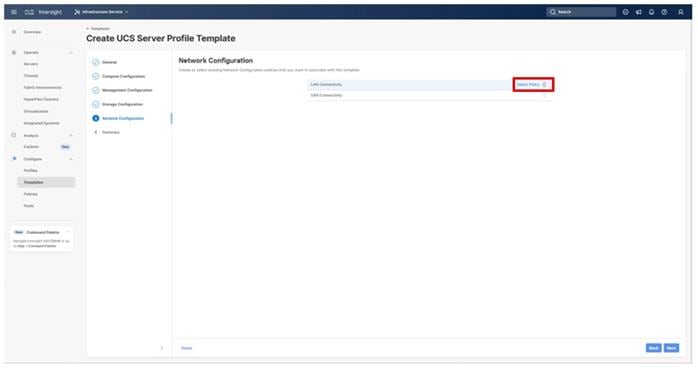
Step 2. Verify that the correct organization is selected from the drop-down list (for example, AA21) and provide a name for the policy (for example, AA21-FC-Boot-LanCon-Pol). Click Next.
Step 3. Click Add vNIC under the vNIC Configuration section.
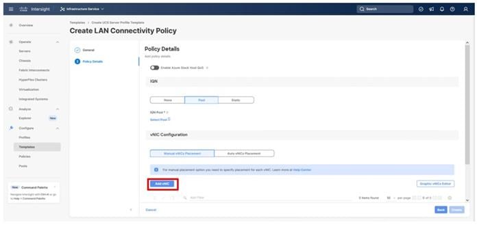
Step 4. Referencing values from Table 14, specify the Name for the vNIC, and under MAC Pool, click Select Pool.
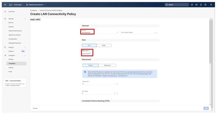
Note: When creating the first vNIC, the MAC address pool has not been defined yet therefore a new MAC address pool will need to be created. Two separate MAC address pools are configured for each fabric. MAC-Pool-A will be reused for all Fabric-A vNICs, and MAC-Pool-B will be reused for all Fabric-B vNICs.
| Pool Name |
Starting MAC Address |
Size |
vNICs |
| MAC-Pool-A |
00:25:B5:21:0A:00 |
256 |
00-vSwitch0-A, 02-VDS0-A |
| MAC-Pool-B |
00:25:B5:21:0B:00 |
256 |
01-vSwitch0-B, 03-VDS0-B |
Note: Each server requires 3 MAC addresses from the pool. Adjust the size of the pool according to your requirements.
Step 5. Select the MAC Pool appropriate fabric or click Create New if one has not been created yet.
Step 6. If creating a new pool, verify that the correct organization is selected from the drop-down list (for example, AA21) and provide a Name for the pool from Table 15 depending on the vNIC being created (for example, MAC-Pool-A for Fabric A).
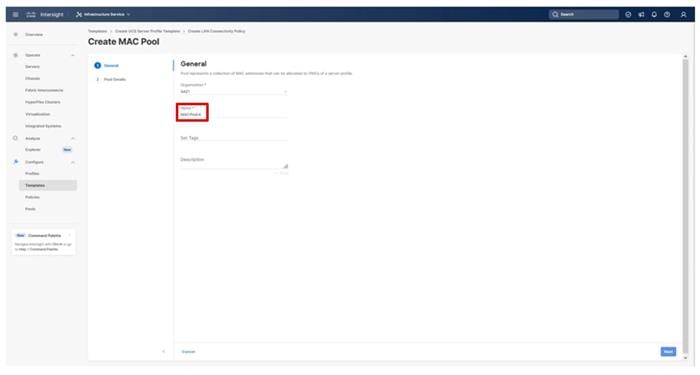
Step 7. Click Next.
Step 8. Provide the starting MAC address from Table 14 (for example, 00:25:B5:21:0A:00)
Step 9. Provide the size of the MAC address pool from Table 15 (for example, 256).
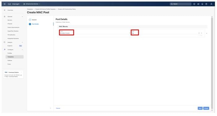
Step 10. Click Create to finish creating the MAC address pool.
Step 11. Confirm the Switch ID and PCI Order values are correct for the vNIC being configured per Table 14.
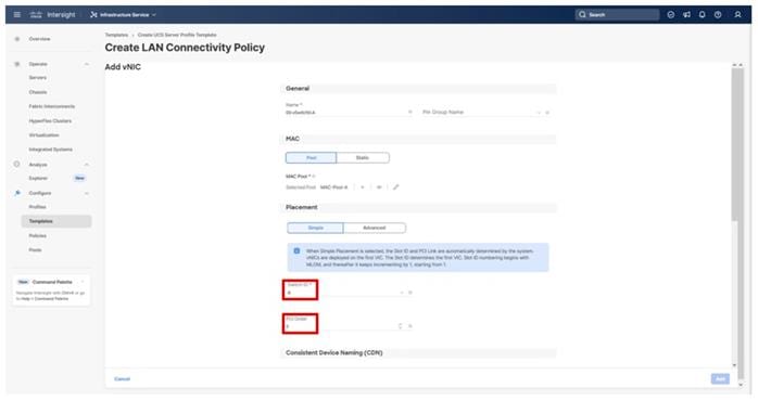
Step 12. Click Select Policy for Ethernet Group Policy.
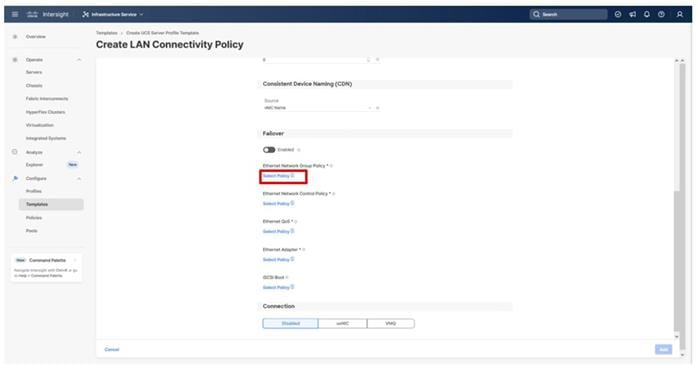
Note: Two Ethernet Network Group Policies will be created, one for vSwitch0 and one for vDS0 to detail the Native VLAN and VLANs that will be carried within the vNICs.
Step 13. When creating the vSwitch0 vNICs and the vSwitch0 Ethernet Network Group Policy is not created, select the Create New option. Select the appropriate policy if it is created and skip the next two steps.
Step 14. Provide a Name for the policy and click Next.
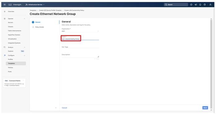
Step 15. Specify the Native VLAN to be used and any VLANs allowed and click Create.
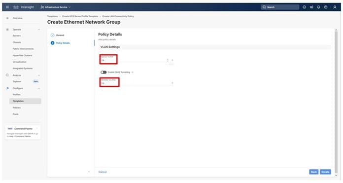
Step 16. When creating the vDS0 vNICs and the vDS0 Ethernet Network Group Policy is not created, select the Create New option. Select the appropriate policy if it is created and skip the next two steps.
Step 17. Provide a Name for the policy and click Next.

Step 18. Specify the Native VLAN to be used and any VLANs allowed and click Create.
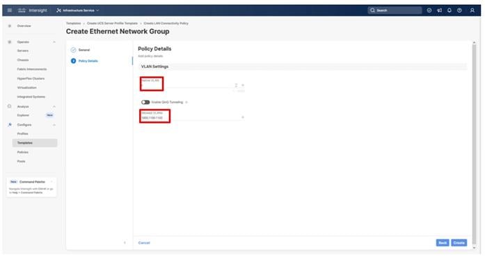
Step 19. For either type of vNIC, click Select Policy under Ethernet Network Control Policy.
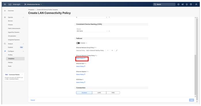
Step 20. Click Create New from the right-hand column that appears or select the Ethernet Network Control Policy if it has already been created and skip the next two steps.
Step 21. Provide a Name for the policy and click Next.
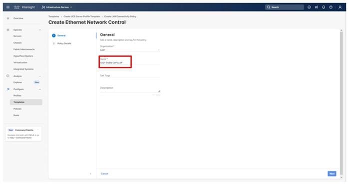
Step 22. Select the Enable CDP toggle and the Enable Transmit and Enable Receive toggles under LLDP, and then click Create.
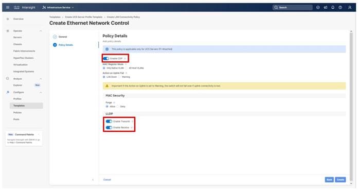
Step 23. For either type of vNIC, click Select Policy under Ethernet QoS.
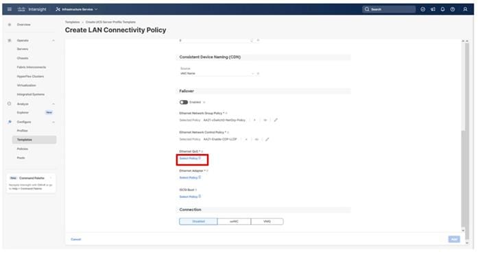
Step 24. Click Create New from the right-hand column that appears or select the Ethernet QoS Policy if it has already been created and skip the next two steps.
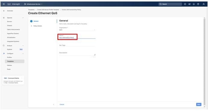
Step 25. Change the MTU Bytes settings to 9000 and click Create.
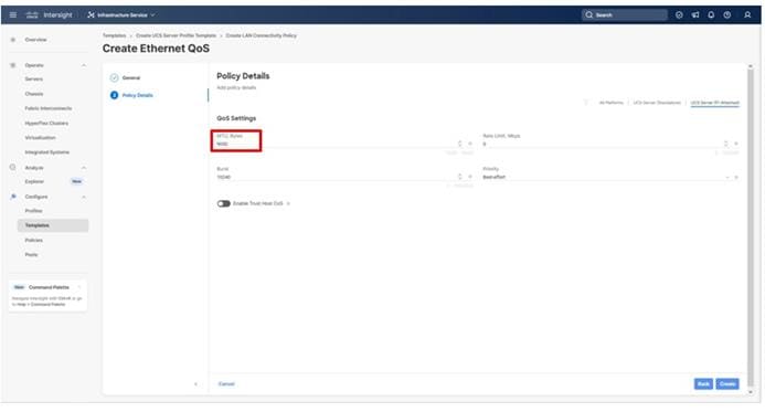
Step 26. For either type of vNIC, click Select Policy under Ethernet Adapter.
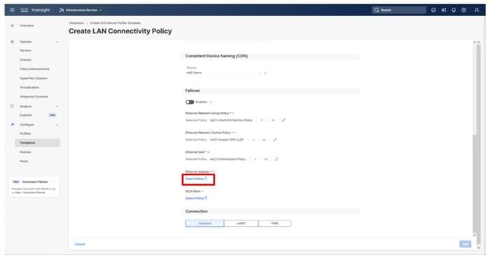
Step 27. Click Create New from the right-hand column that appears or select the Ethernet Adapter Policy if it has already been created and skip the next two steps. One policy will be created for the vSwitch0 vNICs, and a different policy will be created for the vDS0 vNICs.
Step 28. To create the vSwitch0 policy, specify a Name for the policy, and click Select Default Configuration.
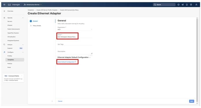
Step 29. Select the VMWare option from the column that appears to the right and click Next.
Step 30. Leave all options set to their default settings in the resulting screen and click Create.
Step 31. To create the vDS0 policy, specify a Name for the higher traffic settings used in the policy, and click Select Default Configuration.
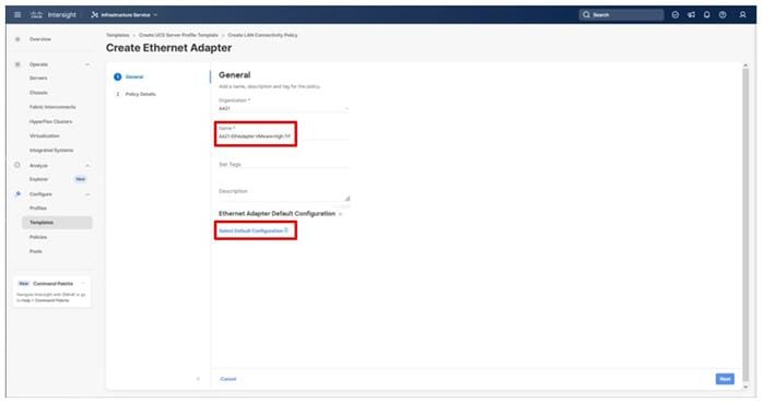
Step 32. Select the VMWare option from the column that appears to the right and click Next.
Step 33. Change the Interrupts to 11, the Receive Queue Count to 8, the Receive Ring Size to 4096, the Transmit Ring Size to 4096, and the Completion Queue Count to 9. Click Create.
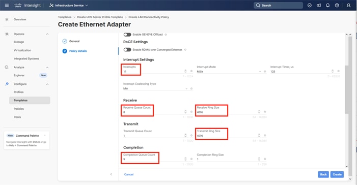
Step 34. Click Add.
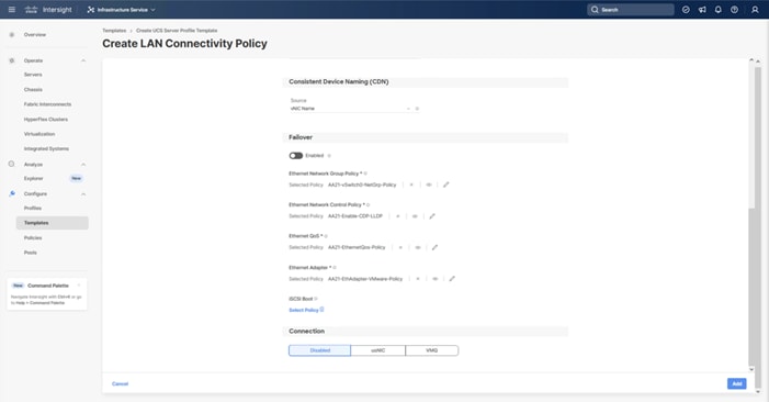
Step 35. Repeat steps 3-34 for each additional vNIC, creating the appropriate pools and policies as required.
Step 36. Click Create to finish the LAN Connectivity Policy.
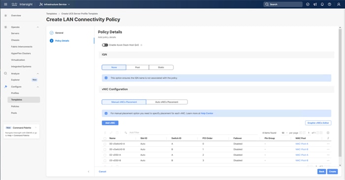
SAN Connectivity
Procedure 1. Create Network Connectivity - SAN Connectivity
A SAN connectivity policy determines the network storage resources and the connections between the server and the storage device on the network. This policy enables you to configure the vHBAs that the servers use to communicate with the SAN.
Table 16 lists the details of four vHBAs that are used to provide FC connectivity, FC boot from SAN functionality, and FC-NVMe connectivity.
Table 16. SAN Connectivity vHBAs
| vNIC/vHBA Name |
Slot |
Switch ID |
PCI Order |
| FC-A |
MLOM |
A |
4 |
| FC -B |
MLOM |
B |
5 |
| FC-NVMe-A |
MLOM |
A |
6 |
| FC-NVMe-B |
MLOM |
B |
7 |
Step 1. Click Select Policy next to SAN Connectivity and in the pane on the right, click Create New.
Step 2. Verify that the correct organization is selected from the drop-down list (for example, AA21) and provide a Name for the policy (for example, AA21-FC-NVMe-FC-SAN). Click Next.
Step 3. Select Manual vHBAs Placement.
Step 4. Click Select Pool under WWNN Address.
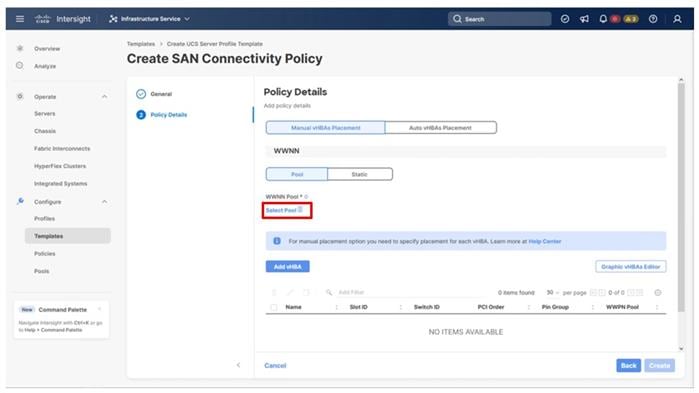
Procedure 2. Create the WWNN Address Pool
The WWNN address pools have not been defined yet therefore a new WWNN Address Pool has to be defined. To create the WWNN address pool, follow these steps:
Step 1. Click Select Pool under WWNN Address Pool and in the pane on the right, click Create New.
Step 2. Verify that the correct organization is selected from the drop-down list (for example, AA21) and provide a name for the policy (for example, AA21-WWNN-Pool).
Step 3. Click Next.
Step 4. Provide the starting WWNN block address and the size of the pool.
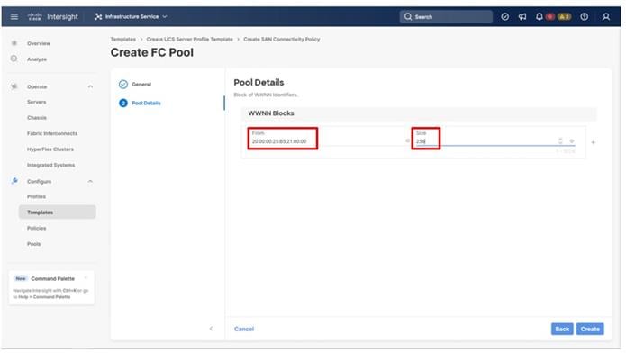
Note: As a best practice, some additional information can be coded into the WWNN address pool for ease of troubleshooting. For example, the address 20:00:00:25:B5:21:00:00 contains a reference to the AA21 rack ID.
Step 5. Click Create to finish creating the WWNN address pool.
Procedure 3. Create the vHBA-A for SAN A
Step 1. Click Add vHBA.
Step 2. Provide the Name (for example, FC-A) and vHBA Type and choose fc-initiator from the drop-down list.
Procedure 4. Create the WWPN Pool for SAN A
The WWPN address pool has not been defined yet therefore a WWPN address pool for Fabric A will be defined. This pool will also be used for the FC-NVMe vHBAs if the vHBAs are defined.
Step 1. Click Select Pool under WWPN Address Pool an in the pane on the right, click Create New.
Step 2. Verify that the correct organization is selected from the drop-down list (for example, AA21) and provide a name for the policy (for example, AA21-WWPN-Pool-A).
Step 3. Provide the starting WWPN block address for SAN A and the size.
Note: As with the WWNN, some additional information can be coded into the WWPN address pool for ease of troubleshooting. For example, the address 20:00:00:25:B5:21:0A:00, 21 references Rack ID 21 and 0A signifies SAN A.
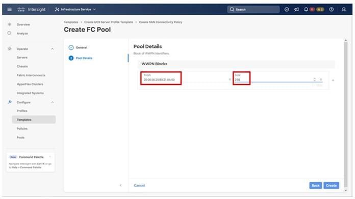
Step 4. Click Create to finish creating the WWPN pool.
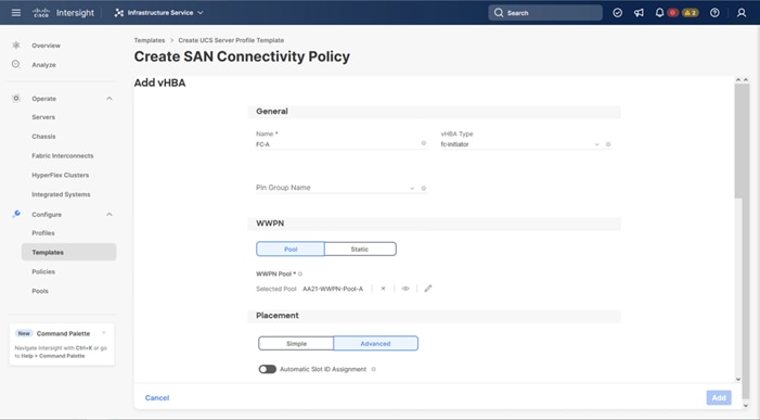
Step 5. Back in the Create vHBA window, using Advanced Placement, specify the Slot ID, Switch ID (for example, A) and PCI Order from Table 16.
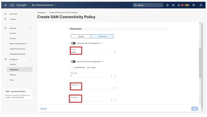
Procedure 5. Create Fibre Channel Network Policy for SAN A
A Fibre Channel network policy governs the VSAN configuration for the virtual interfaces. In this deployment, VSAN 101 will be used for vHBA-A.
Step 1. Scroll down within the Create SAN Connectivity Policy dialogue and click Select Policy under Fibre Channel Network and in the pane on the right, click Create New.
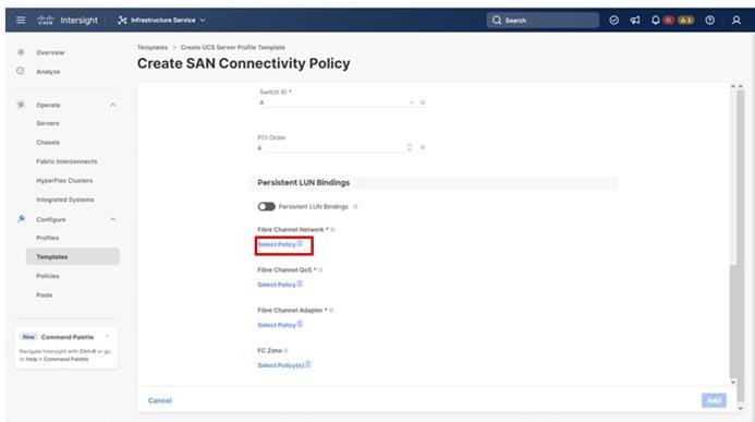
Step 2. Verify that the correct organization is selected from the drop-down list (for example, AA21) and provide a name for the policy (for example, AA21-FC-Network-SAN-A).
Step 3. Specify the VSAN ID for Fabric A, (for example, 101).
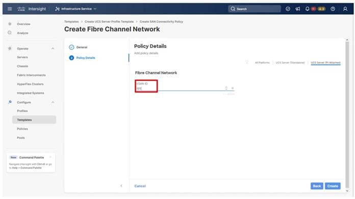
Step 4. Click Create to finish creating the Fibre Channel network policy.
Procedure 6. Create Fibre Channel QoS Policy
The Fibre Channel QoS policy assigns a system class to the outgoing traffic for a vHBA. This system class determines the quality of service for the outgoing traffic. The Fibre Channel QoS policy used in this deployment uses default values and will be shared by all vHBAs.
Step 1. Click Select Policy under Fibre Channel QoS and in the pane on the right, click Create New.
Step 2. Verify that the correct organization is selected from the drop-down list (for example, AA21) and provide a name for the policy (for example, AA21-FC-QoS-Policy).
Step 3. Do not change the default values on the Policy Details screen.
Step 4. Click Create to finish creating the Fibre Channel QoS policy.
Procedure 7. Create Fibre Channel Adapter Policy
A Fibre Channel adapter policy governs the host-side behavior of the adapter, including the way that the adapter handles traffic. This validation uses the default values for the adapter policy, and the policy will be shared by all the vHBAs.
Step 1. Click Select Policy under Fibre Channel Adapter and in the pane on the right, click Create New.
Step 2. Verify that the correct organization is selected from the drop-down list (for example, AA21) and provide a name for the policy (for example, AA21-FC-Adapter).
Step 3. Under Fibre Channel Adapter Default Configuration, click Select Default Configuration.
Step 4. Select VMWare and click Next.
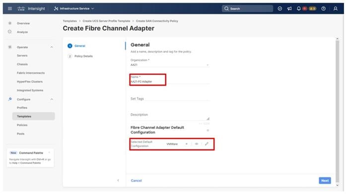
Step 5. Do not change the default values on the Policy Details screen.
Step 6. Click Create to finish creating the Fibre Channel adapter policy.
Step 7. Click Add to create vHBA FC-A.
Procedure 8. Create the vHBA for SAN B
Step 1. Click Add vHBA.
Step 2. For vHBA Type, choose fc-initiator from the drop-down list.
Procedure 9. Create the WWPN Pool for SAN B
The WWPN address pool has not been defined yet therefore a WWPN address pool for Fabric B will be defined. This pool will also be used for the FC-NVMe vHBAs as well.
Step 1. Click Select Pool under WWPN Address Pool and in the pane on the right, click Create New.
Step 2. Verify that the correct organization is selected from the drop-down list (for example, AA21) and provide a name for the policy (for example, AA21-WWPN-Pool-B).
Step 3. Provide the starting WWPN block address for SAN B and the size.
Note: As a best practice, some additional information is once again coded into the WWPN address pool for ease of troubleshooting. For example, the address 20:00:00:25:B5:21:0B:00, 21 contains the rack ID and 0B signifies SAN B.
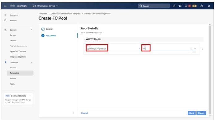
Step 4. Click Create to finish creating the WWPN pool.
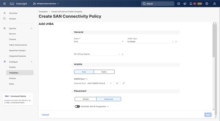
Step 5. Scroll down if needed to add the Slot ID, Switch ID (for example, A) and PCI Order from Table 15.

Procedure 10. Create Fibre Channel Network Policy for SAN B
Note: In this deployment, VSAN 102 is used for vHBA FC-B.
Step 1. Scroll down within the Create SAN Connectivity Policy dialogue and click Select Policy under Fibre Channel Network and in the pane on the right, click Create New.
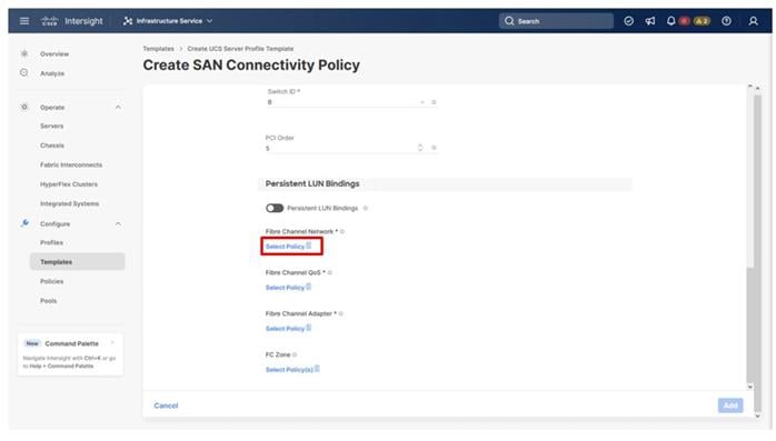
Step 2. Verify that the correct organization is selected from the drop-down list (for example, AA21) and provide a name for the policy (for example, AA21-FC-Network-SAN-B).
Step 3. Specify the VSAN ID for Fabric B (for example, 102).
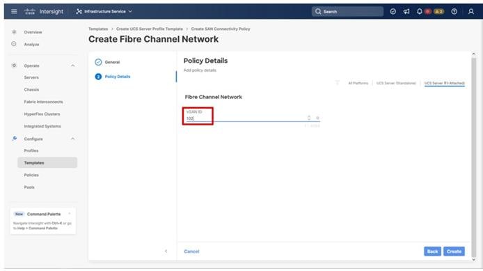
Step 4. Click Create.
Step 5. Select the Fibre Channel QoS Policy for SAN B. Click Select Policy under Fibre Channel QoS and in the pane on the right, select the previously created QoS policy AA21-FC-QoS-Policy.
Step 6. Select the Fibre Channel Adapter Policy for SAN B. Click Select Policy under Fibre Channel Adapter and in the pane on the right, select the previously created Adapter policy AA21-FC-Adapter-Policy.
Step 7. Click Add to add the vHBA FC-B.
Procedure 11. Create the FC-NVMe vHBAs
Note: To configure the FC-NVMe, two vHBAs, one for each fabric, must be added to the server profile template. These vHBAs are in addition to the FC boot from SAN vHBAs, FC-A and FC-B.
Table 17. vHBA placement for NVMe-o-FC
| vNIC/vHBA Name |
Slot |
Switch ID |
PCI Order |
| FC-NVMe-A |
MLOM |
A |
6 |
| FC-NVMe-B |
MLOM |
B |
7 |
Procedure 12. Configure vHBA FC-NVMe-A
Step 1. Click Add vHBA.
Step 2. Name the vHBA FC-NVMe-Fabric-A. For vHBA Type and choose fc-nvme-initiator from the drop-down list.
Step 3. Click Select Pool under WWPN Address Pool and in the pane on the right, select the previously created pool AA21-WWPN-Pool-A.

Step 4. With the Advanced option of Placement selected, scroll down if required to add the Slot ID, Switch ID (for example, A), and PCI Order from Table 16.
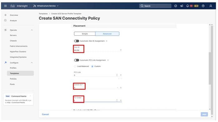
Step 5. Scroll down within the Create SAN Connectivity Policy dialogue and click Select Policy under Fibre Channel Network and in the pane on the right, select the previously created policy for SAN A, AA21-FC-Network-SAN-A.
Step 6. Click Select Policy under Fibre Channel QoS and in the pane on the right, select the previously created QoS policy AA21-FC-QoS-Policy.
Procedure 13. Create FC-NVMe-Initiator Fibre Channel Adapter Policy
A Fibre Channel adapter policy governs the host-side behavior of the adapter, including the way that the adapter handles traffic. The FC-NVMe-Initiator Fibre Channel Adapter Policy is optimized for FC-NVMe.
Step 1. Click Select Policy under Fibre Channel Adapter and in the pane on the right, click Create New.
Step 2. Verify that the correct organization is selected from the drop-down list (for example, AA21) and provide a name for the policy (for example, AA21-FC-NVMe-Initiator-Adapter-Policy).
Step 3. Under Fibre Channel Adapter Default Configuration, click Select Default Configuration.
Step 4. Select FCNVMeInitiator and click Next.
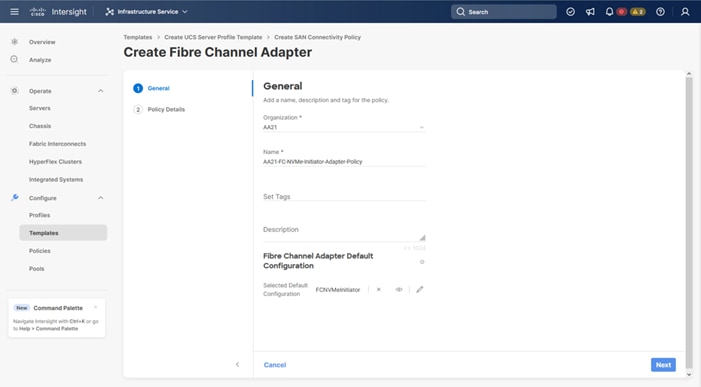
Step 5. Do not change the default values on the Policy Details screen.
Step 6. Click Create to finish creating the Fibre Channel adapter policy.
Step 7. Click Add to create vHBA FC-NVMe-A.
Procedure 14. Configure vHBA FC-NVMe-Fabric-B
Step 1. Click Add vHBA.
Step 2. Name the vHBA FC-NVMe-B. For vHBA Type, select fc-nvme-initiator from the drop-down list.
Step 3. Click Select Pool under WWPN Address Pool and in the pane on the right, select the previously created pool AA21-WWPN-Pool-B.
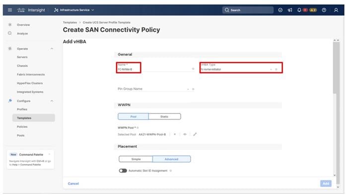
Step 4. Under Advanced Placement, provide the slot ID, Switch ID (for example, B) and PCI Order from Table 16.
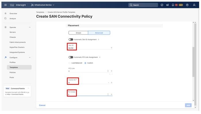
Step 5. Scroll down within the Create SAN Connectivity Policy dialogue and click Select Policy under Fibre Channel Network and in the pane on the right, select the previously created policy for SAN B, AA21-FC-Network-SAN-B.
Step 6. Click Select Policy under Fibre Channel Network and in the pane on the right, select the previously created policy for SAN B, AA21-FC-Network-SAN-B.
Step 7. Click Select Policy under Fibre Channel QoS and in the pane on the right, select the previously created QoS policy AA21-FC-QoS-Policy.
Step 8. Click Select Policy under Fibre Channel Adapter and in the pane on the right, select the previously created Adapter policy AA21-FC-NVMe-Initiator-Adapter-Policy.
Step 9. Click Add to add the FC-NVMe vHBA.
Procedure 15. Verify and create all vHBAs
Step 1. Verify that all four vHBAs are added to the SAN connectivity policy.
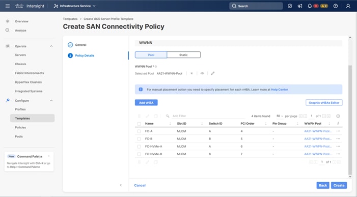
Step 2. Click Create to create the SAN connectivity policy with FC-NVMe support.
Step 1. After the LAN connectivity policy and SAN connectivity policy have been created, click Next to continue to the Summary screen.
Step 2. On the Summary screen, verify that the intended policies are mapped to the appropriate settings.
Figure 3. Compute Configuration
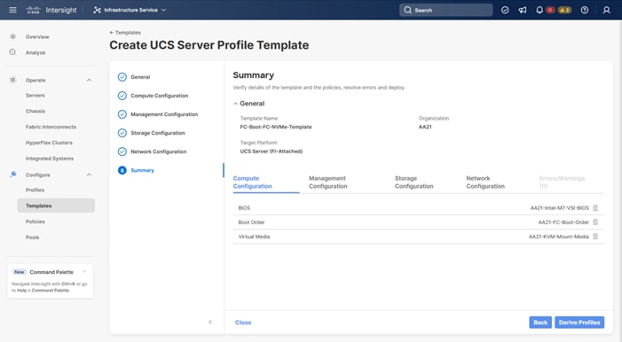
Figure 4. Management Configuration
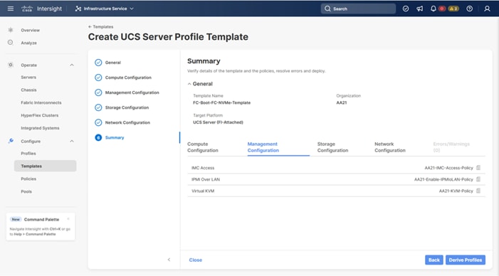
Figure 5. Network Configuration
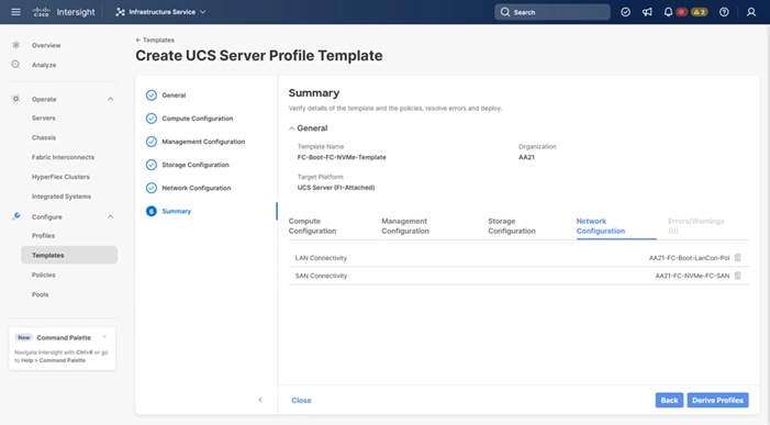
Cisco UCS IMM Setup Completion
Procedure 1. Derive Server Profiles
Step 1. From the Server profile template Summary screen, click Derive Profiles.
Note: This action can also be performed later by navigating to Templates, clicking “…” next to the template name and selecting Derive Profiles.
Step 2. Under Server Assignment, select Assign Now and select Cisco UCS X210c M7 server(s). You can select one or more servers depending on the number of profiles to be deployed. Optionally, provide a Model filter in this screen to exclude additional connected servers as required.
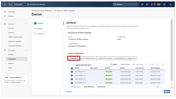
Step 3. Click Next.
Note: Cisco Intersight will fill in the default information for the number of servers selected (4 in this case).
Step 4. Adjust the fields as needed. It is recommended to use the server hostname for the Server Profile name.
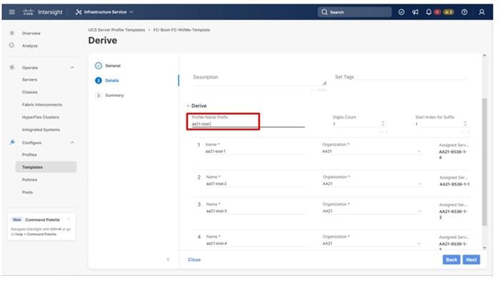
Step 5. Click Next.
Step 6. Verify the information and click Derive to create the Server Profile(s).
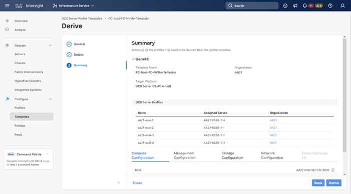
Step 7. In the Infrastructure Service > Configure > Profiles > UCS Server Profiles list, select the profile(s) just created and click the … at the top of the column and select Deploy. Click Deploy to confirm.
Step 8. Cisco Intersight will start deploying the server profile(s) and will take some time to apply all the policies. Use the Requests tab at the top right-hand corner of the window to see the progress.
When the Server Profile(s) are deployed successfully, they will appear under the Server Profiles with the status of OK.
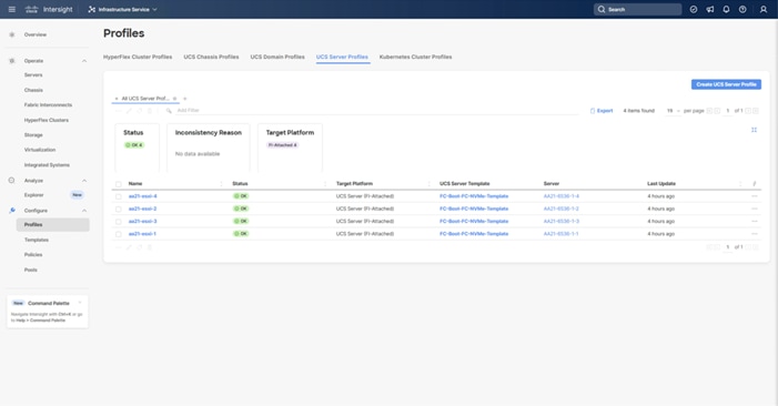
Tunneled KVM Setting within System
Additional settings within the System section of Intersight were mentioned during the Server Profile Template creation process to fully enable Tunneled KVM.
If this is still needed, complete the following procedure.
Procedure 1. Tunneled KVM Setting
Step 1. Go to System > Settings > Security and Privacy and click Configure.
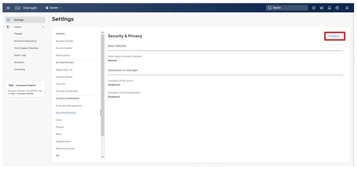
Step 2. Turn on Allow Tunneled vKVM Launch and Allow Tunneled vKVM Configuration.
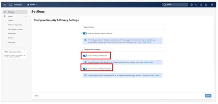
Step 3. Click Save to apply the changes.
Cisco MDS SAN Switch Configuration
This chapter contains the following:
● Global Configuration on Both Switches
● Port and Port-Channel Configuration
● Configure Device Aliases and SAN Zoning
This section explains how to configure the Cisco MDS 9000s for use in the environment. The configuration detailed in this section covers configuring Fibre Channel and FC-NVMe storage access.
Follow the physical connectivity guidelines explained in the Physical Topology section.
The following procedures describe how to configure the Cisco MDS switches for use in the Adaptive Solutions VSI environment. This procedure assumes you are using the Cisco MDS 9124V with NX-OS 9.3(2).
Procedure 1. Set up Cisco MDS 9124V A and 9124V B
Note: On initial boot and connection to the serial or console port of the switch, the NX-OS setup should automatically start and attempt to enter Power on Auto Provisioning. Enter y to get to the System Admin Account Setup.
Step 1. Configure the switch using the command line:
---- System Admin Account Setup ----
Do you want to enforce secure password standard (yes/no) [y]: Enter
Enter the password for "admin": <password>
Confirm the password for "admin": <password>
Would you like to enter the basic configuration dialog (yes/no): yes
Create another login account (yes/no) [n]: Enter
Configure read-only SNMP community string (yes/no) [n]: Enter
Configure read-write SNMP community string (yes/no) [n]: Enter
Enter the switch name : <mds-A-hostname>
Continue with Out-of-band (mgmt0) management configuration? (yes/no) [y]: Enter
Mgmt0 IPv4 address : <mds-A-mgmt0-ip>
Mgmt0 IPv4 netmask : <mds-A-mgmt0-netmask>
Configure the default gateway? (yes/no) [y]: Enter
IPv4 address of the default gateway : <mds-A-mgmt0-gw>
Configure advanced IP options? (yes/no) [n]: Enter
Enable the ssh service? (yes/no) [y]: Enter
Type of ssh key you would like to generate (dsa/rsa) [rsa]: Enter
Number of rsa key bits <1024-2048> [1024]: Enter
Enable the telnet service? (yes/no) [n]: Enter
Configure congestion/no_credit drop for fc interfaces? (yes/no) [y]: Enter
Enter the type of drop to configure congestion/no_credit drop? (con/no) [c]: Enter
Enter milliseconds in multiples of 10 for congestion-drop for logical-type edge
in range (<200-500>/default), where default is 500. [d]: Enter
Enable the http-server? (yes/no) [y]: Enter
Configure clock? (yes/no) [n]: Enter
Configure timezone? (yes/no) [n]: Enter
Configure summertime? (yes/no) [n]: Enter
Configure the ntp server? (yes/no) [n]: Enter
Configure default switchport interface state (shut/noshut) [shut]: Enter
Configure default switchport trunk mode (on/off/auto) [on]: auto
Configure default switchport port mode F (yes/no) [n]: y
Configure default zone policy (permit/deny) [deny]: Enter
Enable full zoneset distribution? (yes/no) [n]: y
Configure default zone mode (basic/enhanced) [basic]: Enter
Step 4. Review the configuration.
Would you like to edit the configuration? (yes/no) [n]: Enter
Use this configuration and save it? (yes/no) [y]: Enter
Step 5. To set up the initial configuration of the Cisco MDS B switch, repeat steps 1 and 2 with appropriate host and IP address information.
Global Configuration on Both Switches
Procedure 1. Enable Features
Note: Run on both Cisco MDS 9124V A and Cisco MDS 9124V B Switches.
Step 1. Log in as admin.
Step 2. Run the following commands:
configure terminal
feature npiv
feature fport-channel-trunk
Procedure 2. Add NTP Servers and Local Time Configuration
Note: Run on both Cisco MDS 9124V A and Cisco MDS 9124V B.
Step 1. From the global configuration mode, run the following command:
ntp server <ntp-server-ip>
clock timezone <timezone> <hour-offset> <minute-offset>
clock summer-time <timezone> <start-week> <start-day> <start-month> <start-time> <end-week> <end-day> <end-month> <end-time> <offset-minutes>
Note: It is important to configure the network time so that logging time alignment, any backup schedules, and SAN Analytics forwarding are correct. For more information on configuring the timezone and daylight savings time or summer time, see Cisco MDS 9000 Series Fundamentals Configuration Guide, Release 9.x. Sample clock commands for the United States Eastern timezone are:
clock timezone EST -5 0
clock summer-time EDT 2 Sunday March 02:00 1 Sunday November 02:00 60
Port and Port-Channel Configuration
Procedure 1. Configure Individual Ports on Cisco MDS 9124V A
Step 1. From the global configuration mode, run the following commands:
channel mode active
switchport trunk allowed vsan <vsan-a-id for example, 101>
switchport description <ucs-domainname>-A
switchport speed 32000
no shutdown
!
interface fc1/1
switchport description <ucs-domainname>-A:1/35/1
channel-group 101 force
port-license acquire
no shutdown
!
interface fc1/2
switchport description <ucs-clustername>-A:1/35/2
channel-group 101 force
port-license acquire
no shutdown
!
interface fc1/3
switchport description <ucs-domainname>-A:1/35/3
channel-group 101 force
port-license acquire
no shutdown
!
interface fc1/4
switchport description <ucs-clustername>-A:1/35/4
channel-group 101 force
port-license acquire
no shutdown
!
interface fc1/5
switchport description <vsp-name>-0:1a
switchport speed 32000
switchport trunk mode off
port-license acquire
no shutdown
!
interface fc1/6
switchport description <vsp-name>-0:1b
switchport speed 32000
switchport trunk mode off
port-license acquire
no shutdown
!
interface fc1/7
switchport description <vsp-name>-1:2a
switchport speed 32000
switchport trunk mode off
port-license acquire
no shutdown
!
interface fc1/8
switchport description <vsp-name>-1:2b
switchport speed 32000
switchport trunk mode off
port-license acquire
no shutdown
Procedure 2. Configure Individual Ports on Cisco MDS 9124V B
Step 1. From the global configuration mode, run the following commands:
interface port-channel102
channel mode active
switchport trunk allowed vsan <vsan-b-id for example, 102>
switchport description <ucs-domainname>-B
switchport speed 32000
no shutdown
!
interface fc1/1
switchport description <ucs-domainname>-B:1/35/1
channel-group 102 force
port-license acquire
no shutdown
!
interface fc1/2
switchport description <ucs-clustername>-B:1/35/2
channel-group 102 force
port-license acquire
no shutdown
!
interface fc1/3
switchport description <ucs-domainname>-B:1/35/3
channel-group 102 force
port-license acquire
no shutdown
!
interface fc1/4
switchport description <ucs-clustername>-B:1/35/4
channel-group 102 force
port-license acquire
no shutdown
!
interface fc1/5
switchport description <vsp-name>-0:3a
switchport speed 32000
switchport trunk mode off
port-license acquire
no shutdown
!
interface fc1/6
switchport description <vsp-name>-0:3b
switchport speed 32000
switchport trunk mode off
port-license acquire
no shutdown
!
interface fc1/7
switchport description <vsp-name>-1:4a
switchport speed 32000
switchport trunk mode off
port-license acquire
no shutdown
!
interface fc1/8
switchport description <vsp-name>-1:4b
switchport speed 32000
switchport trunk mode off
port-license acquire
no shutdown
Note: If the VSAN trunk was not being configured for the port-channel connecting the Cisco UCS Fabric Interconnects to the Cisco MDS switches, do not enter “switchport trunk allowed vsan <vsan-b-id>” for interface port-channel102.
Procedure 3. Create VSANs on Cisco MDS 9124V A
Step 1. From the global configuration mode, run the following commands:
vsan database
vsan <vsan-a-id>
vsan <vsan-a-id> name Fabric-A
exit
zone smart-zoning enable vsan <vsan-a-id>
vsan database
vsan <vsan-a-id> interface fc1/5
Traffic on fc1/5 may be impacted. Do you want to continue? (y/n) [n] y
vsan <vsan-a-id> interface fc1/6
Traffic on fc1/6 may be impacted. Do you want to continue? (y/n) [n] y
vsan <vsan-a-id> interface fc1/7
Traffic on fc1/7 may be impacted. Do you want to continue? (y/n) [n] y
vsan <vsan-a-id> interface fc1/8
Traffic on fc1/8 may be impacted. Do you want to continue? (y/n) [n] y
vsan <vsan-a-id> interface port-channel101
exit
Procedure 4. Create VSANs on Cisco MDS 9124V B
Step 1. From the global configuration mode, run the following commands:
vsan database
vsan <vsan-b-id>
vsan <vsan-b-id> name Fabric-B
exit
zone smart-zoning enable vsan <vsan-b-id>
vsan database
vsan <vsan-b-id> interface fc1/5
Traffic on fc1/5 may be impacted. Do you want to continue? (y/n) [n] y
vsan <vsan-b-id> interface fc1/6
Traffic on fc1/6 may be impacted. Do you want to continue? (y/n) [n] y
vsan <vsan-b-id> interface fc1/7
Traffic on fc1/7 may be impacted. Do you want to continue? (y/n) [n] y
vsan <vsan-b-id> interface fc1/8
Traffic on fc1/8 may be impacted. Do you want to continue? (y/n) [n] y
vsan <vsan-b-id> interface port-channel102
exit
Configure Device Aliases and SAN Zoning
Procedure 1. Gather Target and Initiator WWPNs
These procedures will gather the target and initiator WWPN information from the Hitachi VSP controllers and the Server Profiles associated with the UCS X-Series servers.
Step 1. Go to Ops Center Administrator Dashboard > Storage Systems > [S/N of VSP listing]
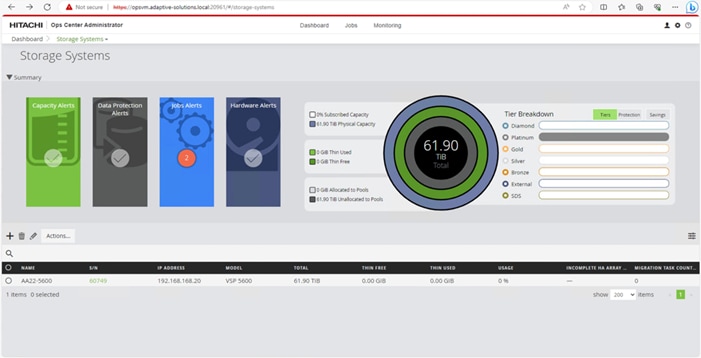
Step 2. From the resulting view, click Ports.
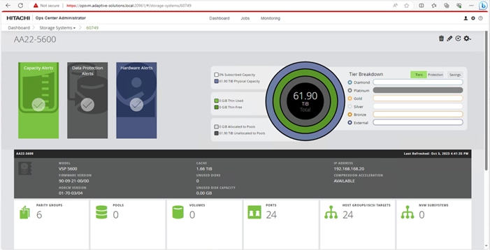
Step 3. Find and gather the WWN for each port connected to the MDS used for FC-SCSI or FC-NVMe traffic.
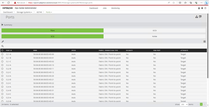
Step 4. Connect to Cisco Intersight to gather the initiator WWPN information for the servers.
Step 5. Find the Server Profiles for each host by going to Infrastructure Service > Configure > Profiles > UCS Server Profiles > <Desired Server Profile> > General > Configuration > Connectivity. The required WWPNs can be found under HBA Interfaces.
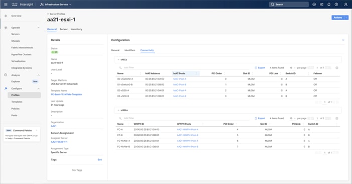
Procedure 2. Create Device Aliases for Fabric A used to Create Zones
Step 1. From the global configuration mode of the Cisco MDS 9124V-A, run the following commands:
device-alias mode enhanced
device-alias database
device-alias name <vsp-name>-0-1a pwwn <vsp-0:1a-wwpn>
device-alias name <vsp-name>-1-2a pwwn <vsp-1:2a-wwpn>
device-alias name <server1-hostname> pwwn <server1-wwpna>
device-alias name <server2-hostname> pwwn <server2-wwpna>
device-alias name <server3-hostname> pwwn <server3-wwpna>
device-alias name <server4-hostname> pwwn <server4-wwpna>
device-alias name <vsp-name>-0-1b-fc-nvme pwwn <vsp-0:1b-wwpn>
device-alias name <vsp-name>-1-2b-fc-nvme pwwn <vsp-0:2b-wwpn>
device-alias name <server1>-fc-nvme pwwn <fc-nvme-server1-wwpna>
device-alias name <server2>-fc-nvme pwwn <fc-nvme-server2-wwpna>
device-alias name <server3>-fc-nvme pwwn <fc-nvme-server3-wwpna>
device-alias name <server4>-fc-nvme pwwn <fc-nvme-server4-wwpna>
Step 2. Commit the device alias database changes:
device-alias commit
Procedure 3. Create Device Aliases for Fabric B used to Create Zones
Step 1. From the global configuration mode of the Cisco MDS 9124V-B, run the following commands:
device-alias mode enhanced
device-alias database
device-alias name <vsp-name>-0-3a pwwn <vsp-0:1a-wwpn>
device-alias name <vsp-name>-1-4a pwwn <vsp-1:2a-wwpn>
device-alias name <server1-hostname> pwwn <server1-wwpnb>
device-alias name <server2-hostname> pwwn <server2-wwpnb>
device-alias name <server3-hostname> pwwn <server3-wwpnb>
device-alias name <server4-hostname> pwwn <server4-wwpnb>
device-alias name <vsp-name>-0-3b-fc-nvme pwwn <vsp-0:1b-wwpn>
device-alias name <vsp-name>-1-4b-fc-nvme pwwn <vsp-0:2b-wwpn>
device-alias name <server1>-fc-nvme pwwn <fc-nvme-server1-wwpnb>
device-alias name <server2>-fc-nvme pwwn <fc-nvme-server2-wwpnb>
device-alias name <server3>-fc-nvme pwwn <fc-nvme-server3-wwpnb>
device-alias name <server4>-fc-nvme pwwn <fc-nvme-server4-wwpnb>
Step 2. Commit the device alias database changes:
device-alias commit
Procedure 4. Create Zones and Zonesets on Cisco MDS 9124V-A
Step 1. To create the required zones for FC on Fabric A, run the following commands:
configure terminal
zone name FC-<vsp-name> vsan <vsan-a-id>
member device-alias <server1-hostname> init
member device-alias <server2-hostname> init
member device-alias <server3-hostname> init
member device-alias <server4-hostname> init
member device-alias <vsp-name>-0-1a target
member device-alias <vsp-name>-1-2a target
exit
Step 2. To create the required zones for FC-NVMe on Fabric A, run the following commands:
zone name FC-NVMe-<vsp-name> vsan <vsan-a-id>
member device-alias <server1>-fc-nvme init
member device-alias <server2>-fc-nvme init
member device-alias <server3>-fc-nvme init
member device-alias <server4>-fc-nvme init
member device-alias <vsp-name>-0-1b-fc-nvme target
member device-alias <vsp-name>-0-2b-fc-nvme target
exit
Step 3. To create the zoneset for the zone(s) defined earlier, run the following command:
zoneset name Fabric-A vsan <vsan-a-id>
member FCP-<vsp-name>
member FC-NVMe-<vsp-name>
exit
Step 4. Activate the zoneset:
zoneset activate name Fabric-A vsan <vsan-a-id>
Step 5. Save the configuration:
copy run start
Note: Because Smart Zoning is enabled, a single zone for each storage protocol (FCP and FC-NVMe) is created with all host initiators and targets for the VSP ports instead of creating separate zones for each host. If a new host is added, its initiator can simply be added to appropriate zone in each MDS switch and the zoneset is reactivated.
Procedure 5. Create Zones and Zonesets on Cisco MDS 9124V-B
Step 1. To create the required zones and zoneset on Fabric B, run the following commands:
configure terminal
zone name FC-<vsp-name> vsan <vsan-b-id>
member device-alias <server1-hostname> init
member device-alias <server2-hostname> init
member device-alias <server3-hostname> init
member device-alias <server4-hostname> init
member device-alias <vsp-name>-0-3a target
member device-alias <vsp-name>-1-4a target
exit
Step 2. To create the required zones for FC-NVMe on Fabric B, run the following commands:
zone name FC-NVMe-<vsp-name> vsan <vsan-b-id>
member device-alias <server1>-fc-nvme init
member device-alias <server2>-fc-nvme init
member device-alias <server3>-fc-nvme init
member device-alias <server4>-fc-nvme init
member device-alias <vsp-name>-0-3b-fc-nvme target
member device-alias <vsp-name>-0-4b-fc-nvme target
exit
Step 3. To create the zoneset for the zone(s) defined above, issue the following command:
zoneset name Fabric-B vsan <vsan-b-id>
member FC-<vsp-name>-B
member FC-NVMe-<vsp-name>-B
exit
Step 4. Activate the zoneset:
zoneset activate name Fabric-B vsan <vsan-b-id>
Step 5. Save the configuration:
copy run start
Hitachi VSP Storage Configuration
This chapter contains the following:
● Hitachi Virtual Storage Platform Configuration for FC-SCSI
● Hitachi Storage Configuration for FC-NVMe
The following procedure explains the initial configuration for the Hitachi Virtual Storage Platform (VSP) storage.
Hitachi Virtual Storage Platform Configuration for FC-SCSI
Procedure 1. Initialize Parity Groups with Hitachi Ops Center Administrator
The configuration steps in this procedure assume that Parity Groups have already been created by Hitachi professional services or from Hitachi Device Manager-Storage Navigator. To initialize Parity Groups from Hitachi Ops Center Administrator, proceed with the following steps:
Step 1. Log in to Hitachi Ops Center Administrator and from the navigation pane, select Storage Systems.

Step 2. Select the respective Virtual Storage Platform S/N from the Storage Systems list.
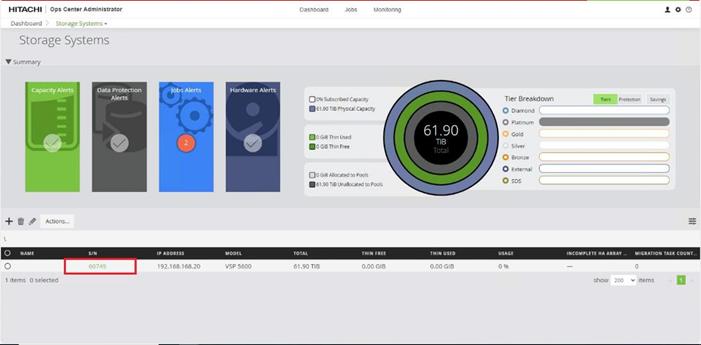
Step 3. Click the PARITY GROUPS icon under the selected storage system to view the Parity Groups.
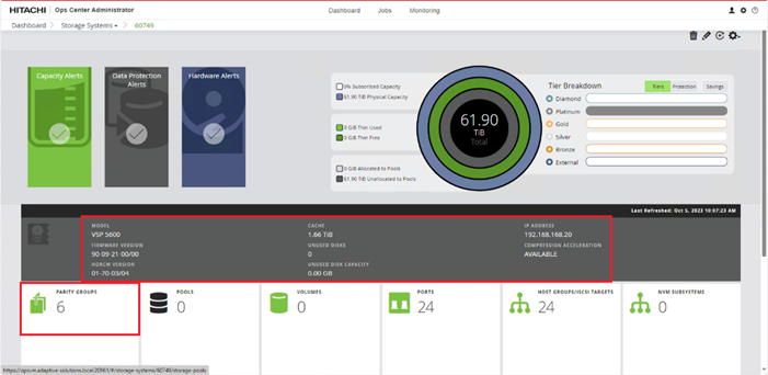

Step 5. Click OK.
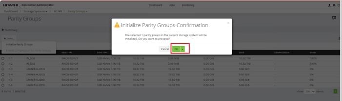
Note: Created Parity Groups initially have a status of UNINITIALIZED. Upon complete initialization, the status should change into IN_USE.
Procedure 2. Create a Hitachi Dynamic Provisioning Pool for UCS Server Boot LDEVs from Hitachi Ops Center Administrator
When creating a pool, select the basic option to leverage tiers of storage available on the VSP, following best practices. By default, the basic option creates a Hitachi Dynamic Provisioning Pool.
For increased flexibility and if best practices are not essential, choose the advanced option. This enables you to specify Parity Groups and define your pool types as either Tiered, Thin, or Snap.
Step 1. Log in to Hitachi Ops Center Administrator, and from the navigation pane, click Storage Systems to access the inventory of registered storage systems.

Step 2. Click the S/N listing of the Storage System.

Step 3. From the selected Storage Systems, click POOLS.

Step 4. Click the plus sign (+), to open the Create Pool window.
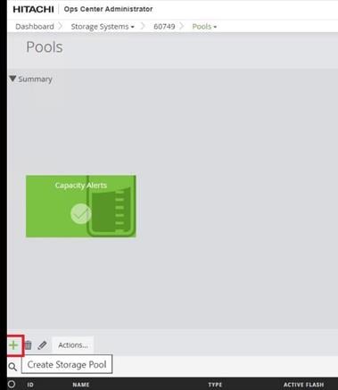
Step 5. Enter the following details:
b. Click an available Tier to view the storage capacity and select the required capacity.
c. Review the high and low pool utilization thresholds. By default, the low utilization threshold is set to 70%, and the high threshold is set to 80%. You can customize these thresholds to receive notifications based on their specific environment requirements.
d. To specify over allocation, you can set the limit to Unlimited.
e. Click Submit.

Procedure 3. Create FC-SCSI Servers from Hitachi Ops Center Administrator
Hitachi Ops Center Administrator supports provisioning storage from logical containers known as servers. These servers that host Cisco UCS server WWNs and the server IP. After Cisco UCS servers are onboarded in Ops Center Administrator, BOOT LDEVs can be provisioned using servers. Proceed with the following steps to create servers from Ops Center Administrator.
Step 1. Log in to Hitachi Ops Center Administrator and from the navigation pane, click Servers.
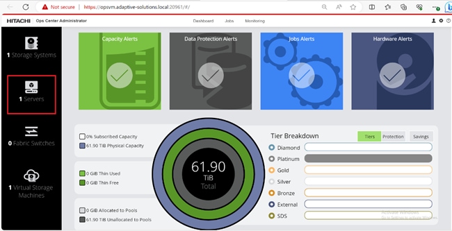
Step 2. Click the plus sign (+) to open the Add Server window.
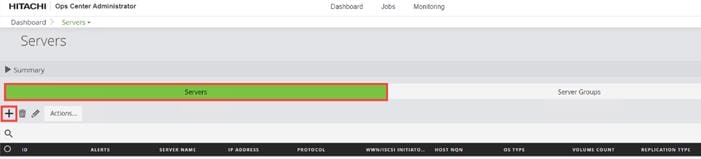
Step 3. Click the plus sign (+) under the Fibre Servers and enter the following server information.
a. SERVER NAME
b. DESCRIPTION
c. IP ADDRESS
d. WWN LIST: Fabric A and Fabric B WWNs of the Cisco UCS Servers
e. OS TYPE: Select the OS TYPE as VMWARE EX.
Step 4. Click Submit to add the server.
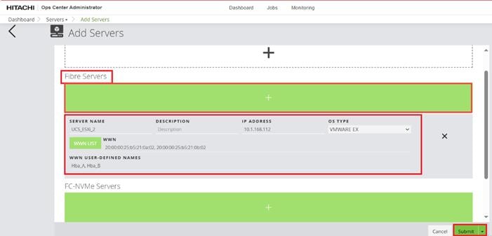
Step 5. Repeat Step 1 through Step 4 for any additional Cisco UCS servers. Upon completion, you can expect the following representation of Cisco UCS servers.
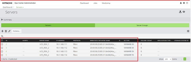
Procedure 4. Create FC-SCSI Server Groups from Ops Center Administrator
The Server Groups are created to manage multiple servers and attach volumes using a single workflow.
Step 1. Log in to Hitachi Ops Center Administrator and from the navigation pane, click Servers.
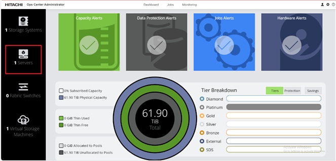
Step 2. Select Server Groups. Click the plus sign (+) icon to open the Add Server Group wizard.

Step 3. In the Add Server Group wizard, enter the SERVER GROUP NAME (for example,VSI_UCS_Cluster_1) and select the Cisco UCS servers that are going to be added to the server group. Click Add to move the selected servers from AVAILABLE SERVERS to ASSIGNED SERVERS.
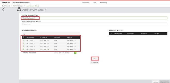
Step 4. Click Submit.
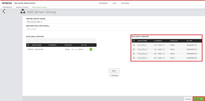
The Server Group (VSI_UCS_Cluster_1) was created and you can find it along with the Server Group ID.
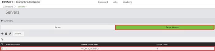
After your server group is created, you can expect the following representation:
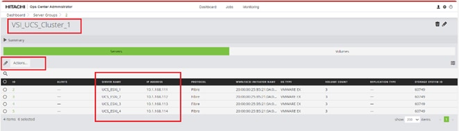
Procedure 5. Allocate Boot LUNs to UCS Servers from Hitachi Ops Center Administrator with Multiple LDEV paths
When allocating Boot LUNs to the Cisco UCS servers, the allocation will be executed on a per-server basis using the Servers logical container.
Step 1. Log in to Hitachi Ops Center Administrator and from the navigation pane, click Servers.
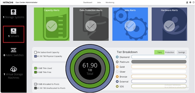
Step 2. Select the Server ID.
Step 3. From the Actions tab, click Attach Volumes and select Create, Attach, and Protect Volumes with Local Replication.
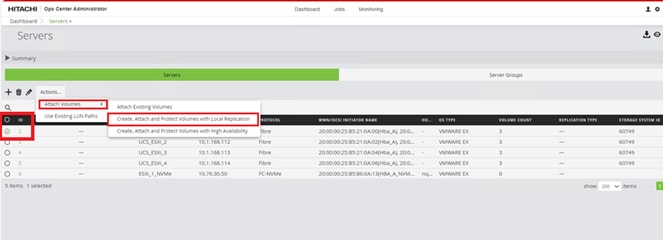
Step 4. Configure volumes for the specified Storage System. To add the volumes to UCS ESXi servers complete the following steps:
a. Verify that the required STORAGE SYSTEM is selected.
b. Select the NUMBER OF VOLUMES as 1.
c. Enter the VOLUME LABEL (for example, ESXi1_Boot_Vol).
d. Enter the volume SIZE (for example, 32 GiB).
e. Select the volume unit as GiB.
f. Select the POOL TYPE as Thin.
Step 5. Click Next to continue.
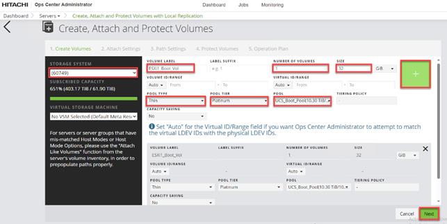
Step 6. Select the following parameters:
a. Set the HOST MODE to VMWARE EX.
b. Select HOST MODE OPTION 63 (VAAI) Support option for vStorage APIs based on T10 standards.
c. Specify the HOST GROUP NAME; for VSI deployments in the context of this document, the nomenclature VSI_x210_M7_xx is used, where xx is the ESXi server ID.
d. Set MANDATE LUN ALIGNMENT as Yes; this option determines whether to assign the same LUN number to multiple servers for a volume. If Yes is specified, the same LUN number is always assigned.
e. Set AUTO CREATE ZONE as No.
f. Click Next.
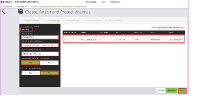
Step 7. In the Path Settings step, you can view servers and their WWNs, along with ports on the storage system and map based on initial zoning configurations. To create a path, click the Cisco UCS server WWNs and click the respective VSP Ports to which it is zoned.
Step 8. You can expect the following representation of the mapping after Path Settings are completed for a single ESXi host. Upon confirming the paths, click Next to view options for protecting volumes.
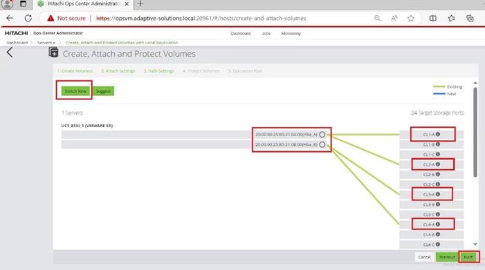
Step 9. Select None and click Next.
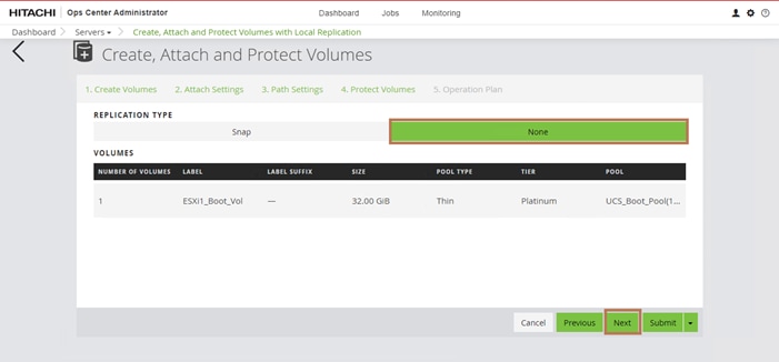

Step 11. From the LUN settings window, using the FROM the drop-down list, select 0, and click OK.
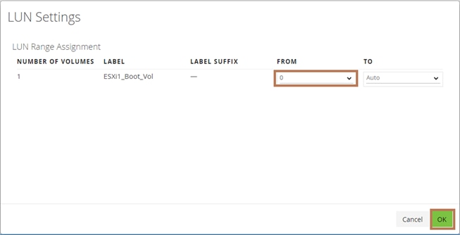
Step 12. Review the Operation plan. Click Submit.
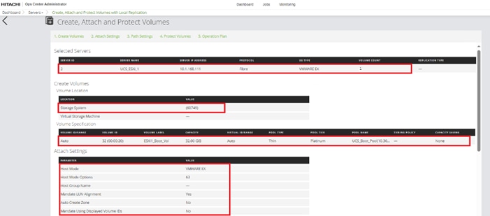
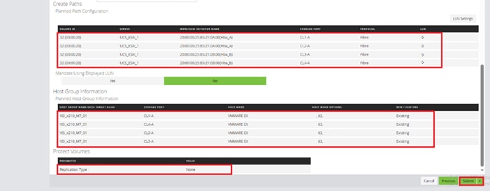
Step 13. Repeat Steps 1 through 12 for any additional Cisco UCS servers.
Procedure 6. Edit Host Groups from Ops Center Administrator for Fabric A and Fabric B Representation
Step 1. Log in to Hitachi Ops Center Administrator and from the navigation pane select Servers.

Step 2. Click the Server ID for UCS_ESXi_1 as shown in the following figure:
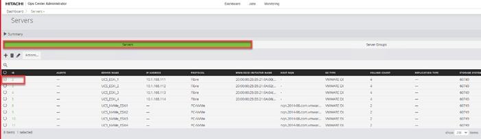
Step 3. Expand the Volume ID of the Boot volume created. Click the Edit pencil icon to edit CL1-A.
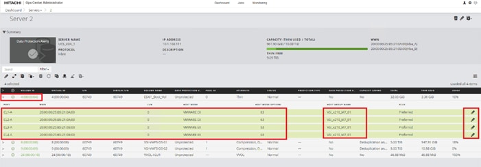
Step 4. In the HOST GROUP NAME text box, update the host group name to include Fabric A. In the specific context outlined in this document, CL1-A for UCS_ESXi_1 is assigned VSI_x210_M7_01_Fab_A as the host group name. Click Submit.
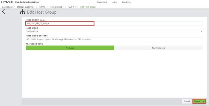
Step 5. Repeat Step 2 through Step 4 for the remaining ports where CL2-A is Fabric A, CL3-A is Fabric B, and CL4- A is Fabric B. When completed, you can expect to see the following:
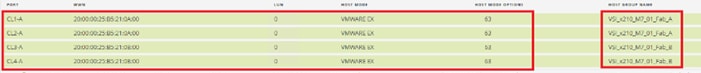
Procedure 7. Create a Hitachi Dynamic Provisioning Pool for FC-SCSI VMFS LDEVs for UCS Servers
When creating a pool, use the basic option to leverage tiers of storage available on the VSP, following best practices. By default, the basic option creates a Hitachi Dynamic Provisioning Pool.
For increased flexibility and if best practices are not essential, choose advanced option. This enables you to select specific Parity Groups and define your pool types as either Tiered, Thin, or Snap.
Step 1. Log in to Hitachi Ops Center Administrator. In the Dashboard, click Storage Systems to access the inventory of registered storage systems.
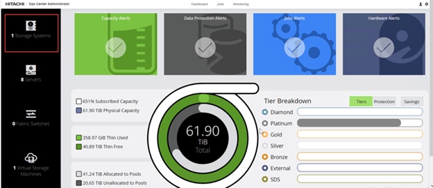
Step 2. Click the S/N listing of the Storage System.
Step 3. From the Storage Systems, click Pools.
Step 4. Click the plus sign (+) to open the Create Pool window.
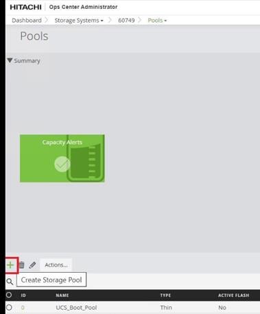
Step 5. Enter the following details:
a. For the POOL NAME enter UCS_Application_Pool (Pool names can be any combination of alphanumeric characters, hyphens, and underscores only. Initial hyphens are not allowed).
b. Click an available Tier to view the storage capacity and select the required capacity.
c. Review the high and low pool utilization thresholds. By default, the low utilization capacity is set to 70%, and high threshold is set to 80%. You can customize thresholds to receive notifications based on their specific environment requirements.
d. To specify over allocation, you can set the limit to Unlimited.
e. Click Submit.
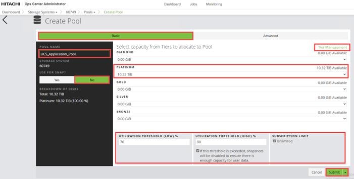
Procedure 8. Allocate FC-SCSI Shared VMFS LDEV and Adding LDEV Paths from Server Groups
Step 1. Log in to Hitachi Ops Center Administrator and from the navigation pane, select Servers.
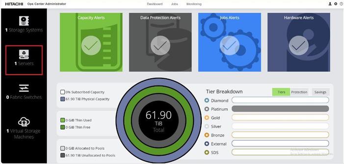
Step 2. From the Servers tab, select Server Groups, and then select a SERVER GROUP ID. Under the Actions, pane select, Attach Volumes, and then click Create, Attach and Protect Volumes with Local Replication.
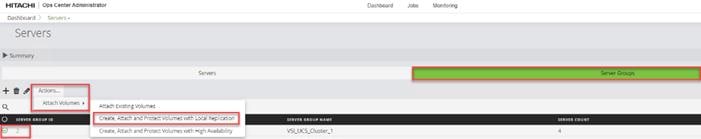
Step 3. Configure volumes for the specified Storage System. You can switch to another Storage System using the Storage System drop-down list. To allocate LDEVs for use as VMFS datastores:
a. For the VOLUME LABEL enter VSI-VMFS-DS.
b. Select the NUMBER OF VOLUMES.
c. Enter the Volume SIZE and select the volume unit: GiB, TiB, or Blocks.
d. Select the POOL TYPE as Thin.
e. For a Thin pool, select the POOL TIER: Diamond, Platinum, Gold, Silver, or Bronze.
f. By default, the POOL is auto selected. Verify that the chosen POOL is the ‘’UCS_Application_Pool’’ for provisioning VMFS datastores.
g. Click the plus sign (+) to verify volume settings.
h. Click Next.
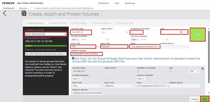
Step 4. The HOST MODE and HOST MODE OPTIONS should be selected as follows:
a. HOST MODE: VMWARE EX.
b. HOST MODE OPTIONS: 63 (VAAI) Support option for vStorage APIs based on T10 standards.
c. Select MANDATE LUN ALIGNMENT as Yes; this option determines whether to assign the same LUN number to multiple servers for a volume. If Yes is specified, the same LUN number is always assigned.
d. Set AUTO CREATE ZONE as No.
Step 5. Click Next to explore options for creating and editing LUN paths.
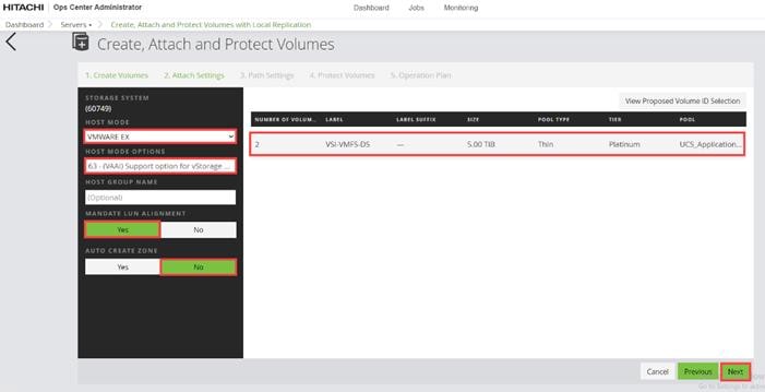
Step 6. On the Path Settings pane, you need to click the respective server WWNs and map them to the VSP storage ports as based on MDS zoning. When completed, you can expect to see the following:
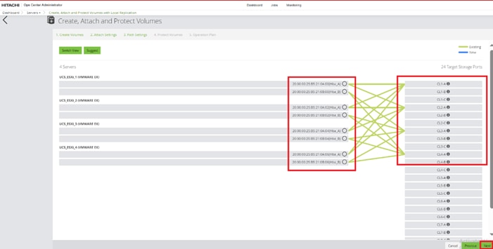
Step 7. For the REPLICATION TYPE select None and click Next.
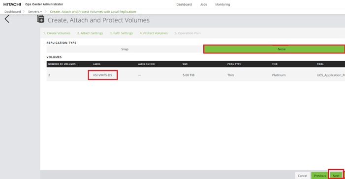
Step 8. If required to modify the LUN ID, click LUN settings. If LUN ID is correct skip to Step 10.
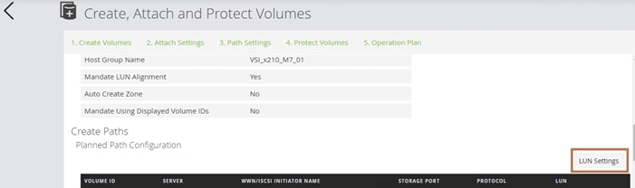
Step 9. From the LUN settings window, choose the appropriate LUN ID using the FROM drop-down list, click OK.
Step 10. Verify the operation plan and click Submit.
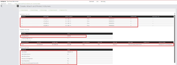
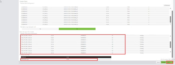
Hitachi Storage Configuration for FC-NVMe
Procedure 1. Configure Fibre Channel Ports on Hitachi Virtual Storage Platform from Ops Center Administrator for FC-NVMe
Note: This procedure must be completed before provisioning the FC-NVMe VMFS datastore.
Step 1. Log in to Hitachi Ops Center Administrator and from the navigation pane, select Storage Systems.

Step 2. Click the S/N listing for the Storage System.

Step 3. Select Fibre Channel Port (for example, CL1-B). Click the Edit sign icon.
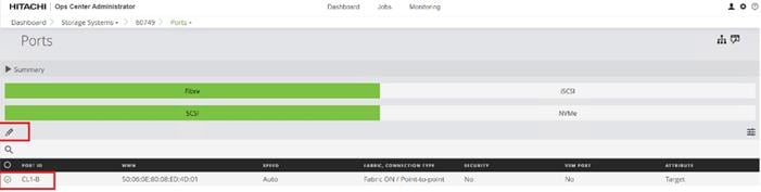
Step 4. Select NVMe Mode and Disable Security and verify that the port attribute is Target. Click OK.
Note: For the VSP E1090 systems, you are not required to modify port attributes.
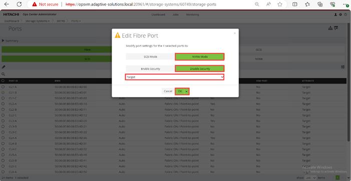
Step 5. Repeat Step 1 through Step 4 for the remaining Fibre ports CL2-B, CL3-B, and CL4-B.
After all the ports are configured, you can expect the following representation:
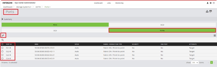
Procedure 2. Initialize Parity Groups from Ops Center Administrator for FC-NVMe
Step 1. Log in to Hitachi Ops Center Administrator and from the navigation pane, select Storage Systems.
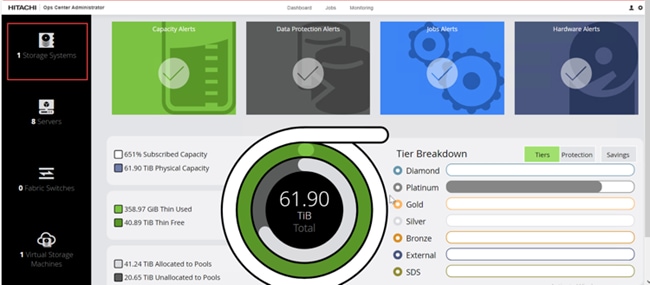
Step 2. Click the S/N listing of the Storage System.

Step 3. Click the PARITY GROUPS icon, under the selected storage system, to view parity groups.

Step 4. Select any Parity Group ID you want to initialize as parity for creating the FC-NVMe pool. From the Actions pane, click Initialize Parity Groups.

Step 5. Click OK.

Note: Created Parity Groups initially have a status of UNINITIALIZED. Upon complete initialization, the status should change into IN_USE.
Procedure 3. Create FC-NVMe Servers from Ops Center Administrator
Step 1. Log in to Hitachi Ops Center Administrator and from the navigation pane, click Servers.

Step 2. Click the plus sign (+) under FC-NVMe Servers section.
Step 3. Enter the SERVER NAME, IP ADDRESS, OS TYPE as VMWARE EX and HOST NQN, and click Submit.
Step 4. Repeat Step 1 through Step 3 to add the remaining Cisco UCS servers that use the FC-NVMe protocol.
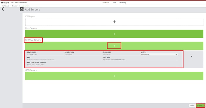
Procedure 4. Create FC-NVMe Server Groups from Ops Center Administrator
Step 1. In the Ops Center Administrator Dashboard, from the navigation pane, click Servers.

Step 2. Select the Server Groups tab. Click the plus sign (+).
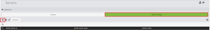
Step 3. In the add Server Group wizard, enter the SERVER GROUP NAME.
Step 4. Select the FC-NVMe Servers from AVAILABLE SERVERS and click Add.
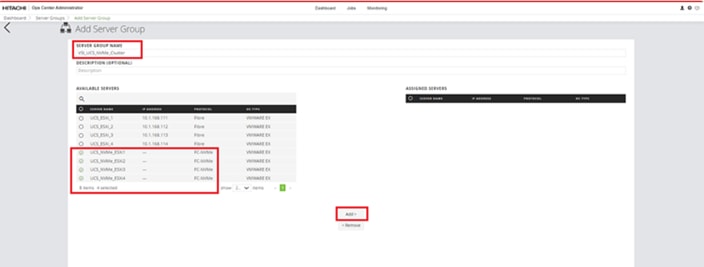
Step 5. The FC-NVMe Servers are moved from the AVAILABLE SERVERS to the ASSIGNED SERVERS list. Click Submit.
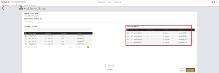
Procedure 5. Create a Hitachi Dynamic Provisioning Pool for UCS Servers for FC-NVMe VMFS Volume LDEVs
When creating a pool, use the basic option to take advantage of tiers of storage available on the VSP, following best practices. By default, the basic option will create a Hitachi Dynamic Provisioning Pool. For increased flexibility and if best practices are not essential, choose the advanced option. This enables you to specify Parity Groups and define your pool types as either Tiered, Thin, or Snap.
Step 1. Log in to Hitachi Ops Center Administrator and from the navigation pane, click Storage Systems to access the inventory of registered storage systems.

Step 2. Click the S/N listing of the Storage System.
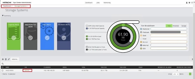
Step 3. From the Storage System, click Pools.

Step 4. Click the plus sign (+) to open the Create Pool window.
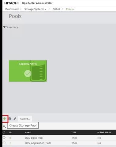
Step 5. Enter the following details:
a. For the POOL NAME enter UCS_Application_NVMe_pool (Pool names can be any combination of alphanumeric characters, hyphens, and underscores only. Initial hyphens are not allowed.)
b. Click an available Tier to view the available storage capacity and select the available capacity.
c. Review the high and low pool utilization thresholds. By default, the low utilization threshold set to 70% and the high threshold is set to 80%. You can customize thresholds to receive notifications based on their specific environment requirements.
d. To specify over allocation, you can set the limit to Unlimited.
e. Click Submit.

Procedure 6. Allocate FC-NVMe Shared VMFS LDEV and Adding LDEV Paths from Server Groups
Step 1. Log in to Hitachi Ops Center Administrator console and click the Servers tab.

Step 2. Select the Server Groups under the Servers tab, and then select Server Group ID.
Step 3. Under Actions, click Attach Volumes, select Create, Attach and Protect Volumes with Local Replication.
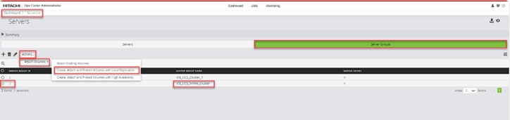
Step 4. Configure volumes for the specified storage System. Proceed with the following steps to add the volumes to UCS ESXi servers that use the FC-NVMe protocol.
a. For the VOLUME LABEL enter VSI-VMFS-DS-NVMe.
b. Select the NUMBER OF VOLUMES.
c. Enter the Volume SIZE. And select the volume unit: GiB, TiB, or Blocks.
d. For the POOL TYPE select Thin.
e. For a Thin pool, select the POOL TIER: Diamond, Platinum, Gold, Silver, or Bronze
f. By default, the POOL is auto selected. Verify that the chosen POOL is the ‘’UCS_Application_NVMe_Pool’’ for provisioning VMFS datastores.
g. Click the plus sign (+) to verify the volume settings.
h. Click Next.
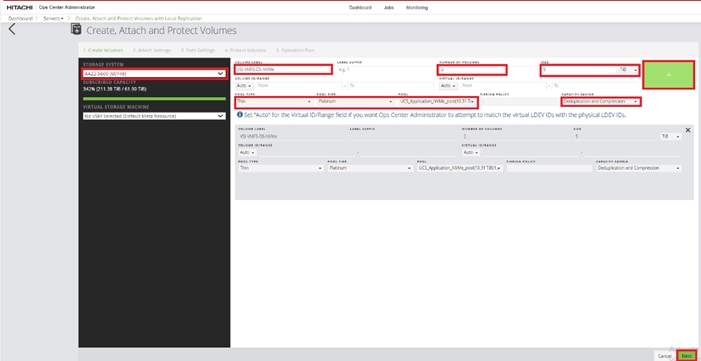
Step 5. For the HOST MODE select VMWARE EX.
Step 6. Validate the Volume values and click Next.
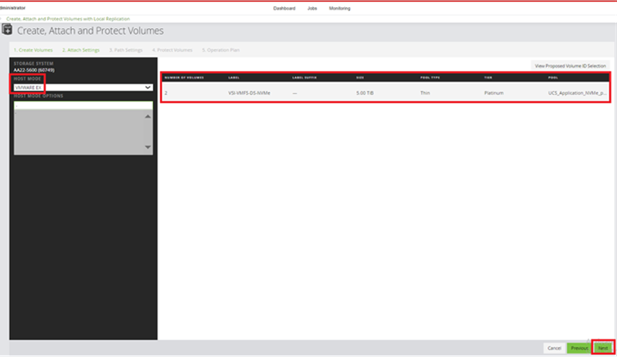
Step 7. Under Path Settings, select the VSP ports that are in NVMe mode, and click Next.
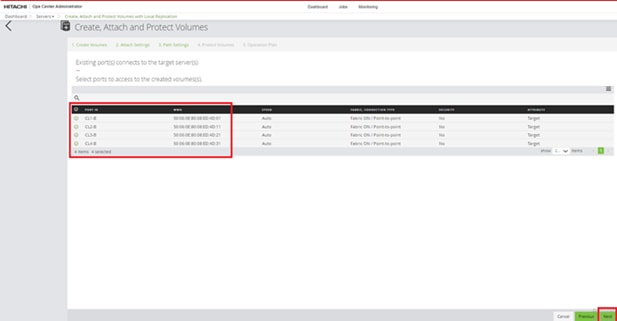
Step 8. Select None for Replication Type and click Next.
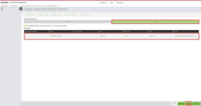
Step 9. Validate Selected Servers, Volume Specification, and Create Paths. Click Submit.
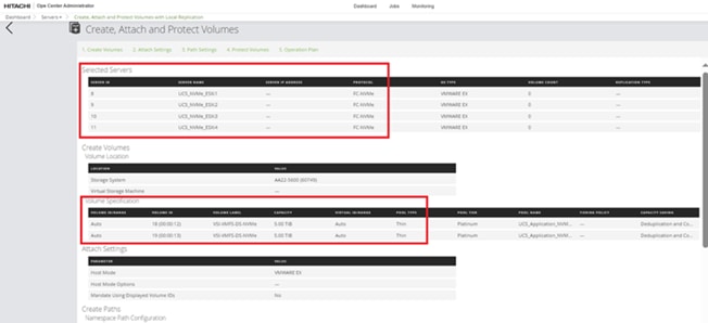
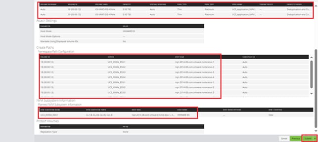
This chapter contains the following:
● Cisco Intersight Hardware Compatibility List (HCL) Status
● Deploy Cisco Intersight Assist Appliance
● Claim VMware vCenter using Cisco Intersight Assist Appliance
● Claim Cisco Nexus Switches using Cisco Intersight Assist Appliance
● Claim Cisco MDS Switches using Cisco Intersight Assist Appliance
● Claim Hitachi VSP using Cisco Intersight Assist Appliance
● Cisco Nexus Dashboard Fabric Controller
Cisco Intersight Hardware Compatibility List (HCL) Status
Cisco Intersight evaluates the compatibility your UCS system to check if the hardware and software have been tested and validated by Cisco or Cisco partners. Cisco Intersight reports validation issues after checking the compatibility of the server model, processor, firmware, adapters, operating system, and drivers, and displays the compliance status with the Hardware Compatibility List (HCL).
To determine HCL compatibility for VMware ESXi, Cisco Intersight uses Cisco UCS Tools as an installed VIB (vSphere Installation Bundle). The Cisco UCS Tools is part of VMware ESXi Cisco custom ISO, but the version for will be updated later during the vSphere Cluster image update.
For more information about Cisco UCS Tools manual deployment and troubleshooting, go to: https://intersight.com/help/saas/resources/cisco_ucs_tools
Procedure 1. View Compute Node Hardware Compatibility
Step 1. To find detailed information about the hardware compatibility of a compute node, in Cisco Intersight go to Infrastructure Service > Operate > Servers in the left menu bar, click a server and select HCL.

Deploy Cisco Intersight Assist Appliance
Cisco Intersight works with Hitachi VSP and VMware vCenter using third-party device connectors and Cisco Nexus and MDS switches using Cisco device connectors. Since third-party infrastructure and Cisco switches do not contain any usable built-in Intersight device connector, Cisco Intersight Assist virtual appliance enables Cisco Intersight to communicate with these devices.
Note: A single Cisco Intersight Assist virtual appliance can support both the Hitachi VSP storage, VMware vCenter, and Cisco Nexus and MDS switches.
To install Cisco Intersight Assist from an Open Virtual Appliance (OVA), download the latest release of the Cisco Intersight Virtual Appliance for vSphere from https://software.cisco.com/download/home/286319499/type/286323047/release/1.0.9-588?catid=268439477
Procedure 1. Set up Intersight Assist DNS entries
Setting up Cisco Intersight Virtual Appliance requires an IP address and 2 hostnames for that IP address. The hostnames must be in the following formats:
● myhost.mydomain.com: A hostname in this format is used to access the GUI. This must be defined as an A record and PTR record in DNS. The PTR record is required for reverse lookup of the IP address. If an IP address resolves to multiple hostnames, the first one in the list is used.
● dc-myhost.mydomain.com: The “dc-“ must be prepended to your hostname. This hostname must be defined as the CNAME of myhost.mydomain.com. Hostnames in this format are used internally by the appliance to manage device connections.
In this lab deployment the following example information was used to deploy a Cisco Intersight Assist VM:
● Hostname: as-assist.adaptive-solutions.local
● IP address: 10.1.168.99
● DNS Entries (Windows AD/DNS):
◦ A Record: as-assist.adaptive-solutions.local
◦ CNAME: dc-as-assist.adaptive-solutions.local
For more details, go to https://www.cisco.com/c/en/us/td/docs/unified_computing/Intersight/b_Cisco_Intersight_Appliance_Getting_Started_Guide/b_Cisco_Intersight_Appliance_Install_and_Upgrade_Guide_chapter_00.html.
Procedure 2. Deploy Cisco Intersight OVA
Note: Ensure that the appropriate entries of type A, CNAME, and PTR records exist in the DNS, as explained in the previous section. Log into the vSphere Client and select Hosts and Clusters.
Step 1. From Hosts and Clusters, right-click the cluster and click Deploy OVF Template.
Step 2. Select Local file and click UPLOAD FILES. Browse to and select the intersight-appliance-installer-vsphere-1.0.9-588.ova or the latest release file and click Open. Click NEXT.
Step 3. Name the Intersight Assist VM and select the location. Click NEXT.
Step 4. Select the cluster and click NEXT.
Step 5. Review details, click Ignore, and click NEXT.
Step 6. Select a deployment configuration. If only the Intersight Assist functionality is needed, the default configuration of 16 CPU and 32GB of RAM can be used. Click NEXT.
Step 7. Select the appropriate datastore (for example, VSI-DS-01) for storage and select the Thin Provision virtual disk format. Click NEXT.
Step 8. Select the appropriate management network (for example, IB-MGMT Network) for the OVA. Click NEXT.
Note: The Cisco Intersight Assist VM must be able to access both the IB-MGMT network if holding the vCenter, OOB for connecting to the switches and the SVP of the 5600, and intersight.com. Select and configure the management network appropriately. If selecting IB-MGMT network on, make sure the routing and firewall is set up correctly to access the Internet and OOB as needed.
Step 9. Fill in all values to customize the template. Click NEXT.
Step 10. Review the deployment information and click FINISH to deploy the appliance.
Step 11. When the OVA deployment is complete, right-click the Intersight Assist VM and click Edit Settings.
Step 12. Expand CPU and verify the socket configuration. For example, in the following deployment, on a 2-socket system, the VM was configured for 16 sockets:
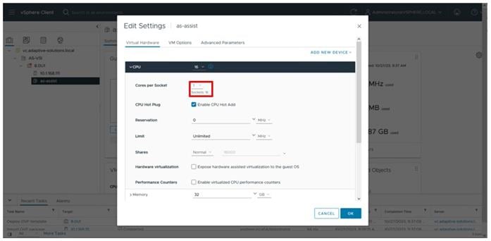
Step 13. Adjust the Cores per Socket so that the number of Sockets matches the server CPU configuration (2 sockets in this deployment):
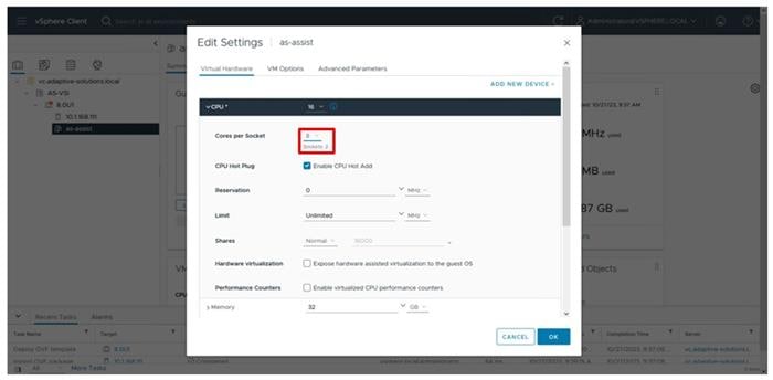
Step 14. Click OK.
Step 15. Right-click the Intersight Assist VM and select Power > Power On.
Step 16. When the VM powers on and the login prompt is visible (use remote console), connect to https://intersight-assist-fqdn.
Note: It may take a few minutes for https://intersight-assist-fqdn to respond.
Step 17. Navigate the security prompts and select Intersight Assist. Click Start.
Note: If a screen appears prior to the certificate security prompt, the assist may not be ready, and a page refresh may be needed.
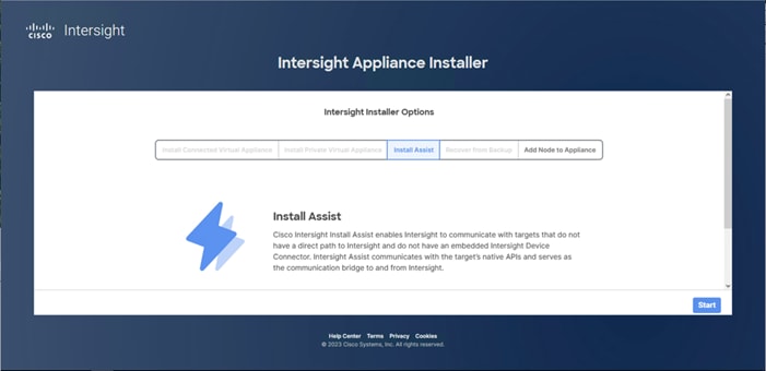
Step 18. Cisco Intersight Assist VM needs to be claimed in Cisco Intersight using the Device ID and Claim Code information visible in the GUI.
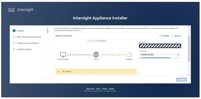
Step 19. Log into Cisco Intersight and connect to the appropriate account.
Step 20. From Cisco Intersight, at the top select System, then click Administration > Targets.
Step 21. Click Claim a New Target. Select Cisco Intersight Assist and click Start.
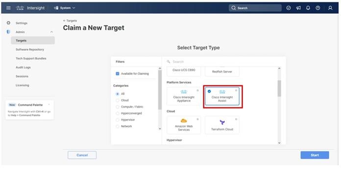
Step 22. Copy and paste the Device ID and Claim Code shown in the Intersight Assist web interface to the Cisco Intersight Device Claim window.
Step 23. Select the Resource Group and click Claim.
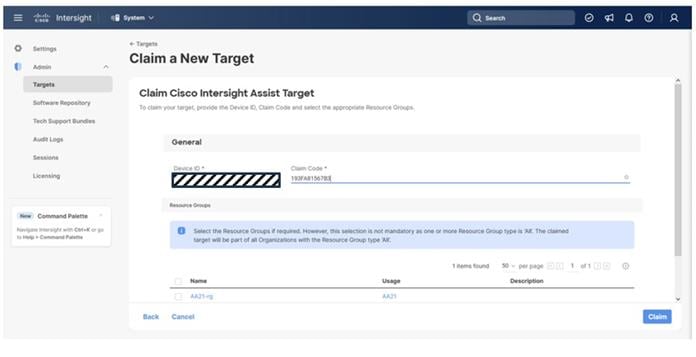
Intersight Assist now appears as a claimed device.
Step 24. In the Intersight Assist web interface, verify that Intersight Assist is Connected Successfully, and click Continue.
Step 25. Step through the additional network requirement checks and internal network configuration before starting the installation update.
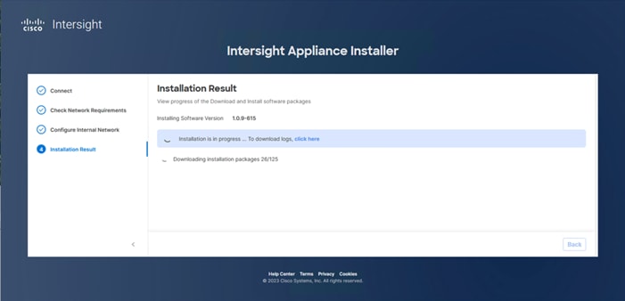
Note: The Cisco Intersight Assist software will now be downloaded and installed into the Intersight Assist VM. This can take up to an hour to complete and the Assist VM will be rebooted during this process. It may be necessary to refresh the web browser after the Assist VM has rebooted.
When the software download is complete, an Intersight Assist login screen appears.
Claim VMware vCenter using Cisco Intersight Assist Appliance
Procedure 1. Claim the vCenter from Cisco Intersight
Step 1. Log into Cisco Intersight and connect to the account registered to the Intersight Assist.
Step 2. Go to System > Administration > Targets and click Claim a New Target.
Step 3. Under Select Target Type, select VMware vCenter under Hypervisor and click Start.
Step 4. In the VMware vCenter window, verify the correct Intersight Assist is selected.
Step 5. Fill in the vCenter information. Enable Hardware Support Manager (HSM) to be able to upgrade the IMM server firmware from VMware Lifecycle Manager. If Intersight Workflow Optimizer (IWO) will be used, turn on Datastore Browsing Enabled and Guest Metrics Enabled. Click Claim.
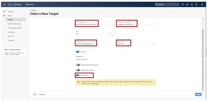
Step 6. After a few minutes, the VMware vCenter will show Connected in the Targets list and will also appear under Infrastructure Service > Operate > Virtualization.
Step 7. Detailed information obtained from the vCenter can now be viewed by clicking Infrastructure Service > Operate > Virtualization and selecting the Datacenters tab. Other VMware vCenter information can be obtained by navigating through the Virtualization tabs.
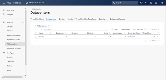
Procedure 2. Interact with Virtual Machines
VMware vCenter integration with Cisco Intersight allows you to directly interact with the virtual machines (VMs) from the Cisco Intersight dashboard. In addition to obtaining in-depth information about a VM, including the operating system, CPU, memory, host name, and IP addresses assigned to the virtual machines, you can use Cisco Intersight to perform the following actions on the virtual machines:
● Start/Resume
● Stop
● Soft Stop
● Suspend
● Reset
● Launch VM Console
Step 1. Log into Cisco Intersight.
Step 2. Go to Infrastructure Service > Operate > Virtualization.
Step 3. Click the Virtual Machines tab.
Step 4. Click “…” to the right of a VM and interact with various VM options.
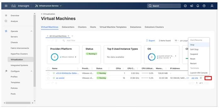
Step 5. To gather more information about a VM, click a VM name.
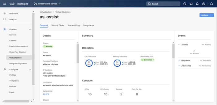
Claim Cisco Nexus Switches using Cisco Intersight Assist Appliance
Procedure 1. Claim Cisco Nexus Switches (Optional)
Cisco Intersight can give direct visibility to Nexus switches independent of Cisco Nexus Dashboard Fabric Controller.
Step 1. Log into Cisco Intersight.
Step 2. Go to System > Administration > Targets.
Step 3. Click Claim a New Target. In the Select Target Type window, select Cisco Nexus Switch under Network and click Start.
Step 4. In the Claim Cisco Nexus Switch Target window, verify the correct Intersight Assist is selected.
Step 5. Fill in the Cisco Nexus Switch information and click Claim.
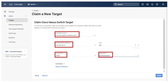
Step 6. Repeat Step 1 through Step 5 to add the second Cisco Nexus Switch.
Step 7. After a few minutes, the two switches will appear under Infrastructure Service > Operate > Networking > Ethernet Switches.
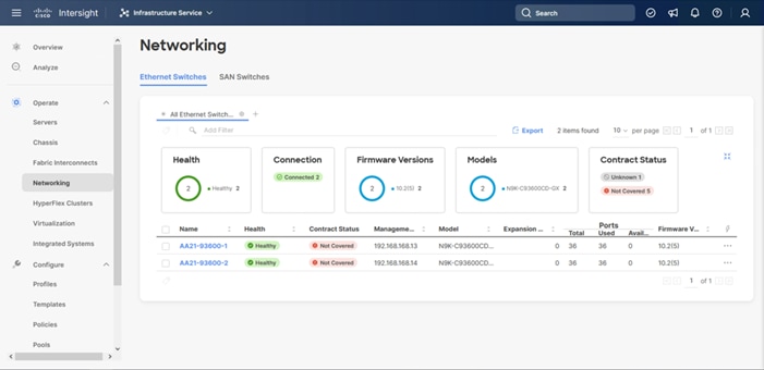
Step 8. Click one of the switch names to get detailed General and Inventory information on the switch.
Claim Cisco MDS Switches using Cisco Intersight Assist Appliance
Procedure 1. Claim Cisco MDS Switches (Optional)
Cisco Intersight can also give direct visibility to the MDS switches independent of Cisco Nexus Dashboard Fabric Controller. At the time of the writing of this document, adding the MDS as targets was still in Tech Preview, so care should be used in relying on received data for this feature in a production setting. To add the MDS switches, follow this procedure:
Step 1. Log in to Cisco Intersight.
Step 2. Go to System > Administration > Targets.
Step 3. Click Claim a New Target. In the Select Target Type window, select Cisco MDS Switch under Network and click Start.
Step 4. In the Claim Cisco MDS Switch Target window, verify the correct Intersight Assist is selected.
Step 5. Fill in the Cisco MDS Switch information, including use of Port 8443 and click Claim.
Note: You can use the admin user login account on the switch.
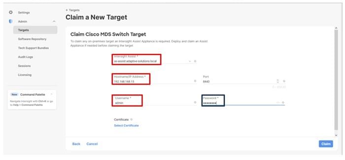
Step 6. Repeat Step 1 through Step 5 to add the second Cisco MDS Switch.
Step 7. After a few minutes, the two switches will appear under Infrastructure Service > Operate > Networking > SAN Switches.
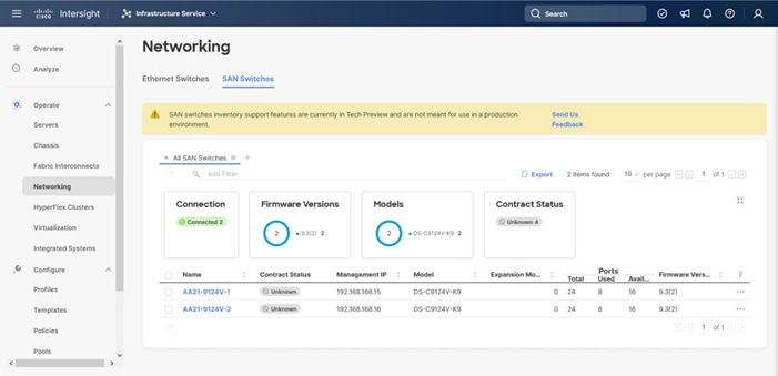
Step 8. Click one of the switch names to get detailed General and Inventory information on the switch.
Claim Hitachi VSP with Cisco Intersight Appliance
Before onboarding the Hitachi VSP to Cisco Intersight, the prerequisites outlined in the following document need to be completed. Refer to the Integrating Hitachi Virtual Storage Platform with Cisco Intersight Quick Start Guide.
Begin State
● Hitachi virtual storage platform should be online and operational, but not claimed by Cisco Intersight.
● Intersight assist VM should be deployed using the Cisco provided OVA template.
● Hitachi Ops Center API Configuration Manager Rest should also be deployed as a VM or server, from a template or with manual installation, so that we can communicate between Cisco Intersight and Hitachi VSP storage. Hitachi Ops Center API Configuration Manager provides the Web API for getting information or changing the configuration of storage systems. Hitachi Ops Center API Configuration Manager is required to use Hitachi Virtual Storage Platform storage systems with Cisco Intersight.
● Communication between Hitachi Ops Center API Configuration Manager and the REST API client.
End State
● Cisco Intersight is communicating with Intersight assist.
● Hitachi VSP is onboarded via Hitachi Ops Center API configuration manager Rest.
● Hitachi VSP is claimed as a device with Cisco Intersight.
Procedure 1. Register Hitachi Virtual Storage Platform to Ops Center Configuration Manager Server
Step 1. Open your respective API client.
Step 2. Enter the base URL for the deployed Hitachi Ops Center API Configuration Manager IP address. For example, https://[Ops_Center_IP]:23450/ConfigurationManager/v1/objects/storages.
Step 3. Click the Authorization tab.
a. Select Basic from the Select authorization drop-down list.
b. Enter the Username and Password for the VSP storage system.
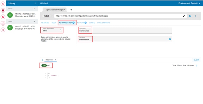
Step 4. Click the Body tab. Enter the VSP storage SVP IP, Serial Number, and Model as indicated in the following examples in JSON format.
Note: If a midrange VSP storage, it will be CTL1 and CTL2 IP instead of SVP IP.
The following example uses a VSP 5600:
{
“svpIp”: “192.168.1.10”,
“serialNumber”: 60749,
“model”: “VSP 5600”
}
The following example uses a VSP E1090:
{ “ctl1Ip”: “192.168.1.10”,
“ctl2Ip”: “192.168.1.11”,
“model”: “VSP E1090”,
“serialNumber”: 451139 }
Step 5. Under the HEADERS tab verify the following:
a. Accept: application/json
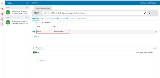
Step 6. Verify that the REST call is set to POST. Click Submit.
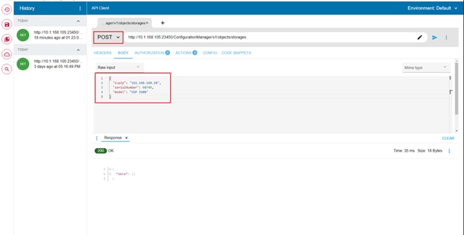
Step 7. After successful registration, a response header is displayed as 200 OK.
Step 8. To confirm onboarding, the API parameter can be updated to the GET method to retrieve storage system information and can be verified with 200 OK status.
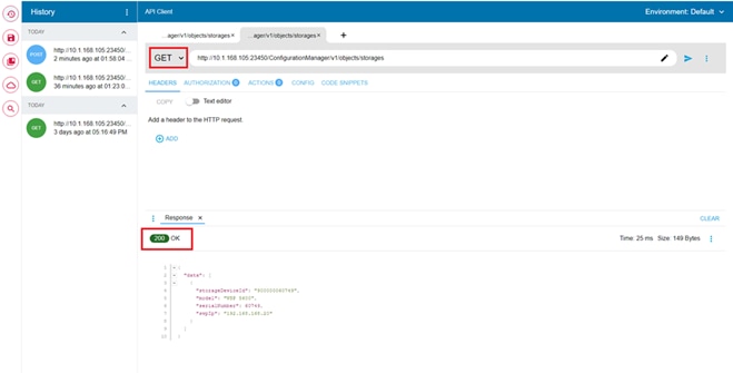
Procedure 2. Onboarding VSP storage to Cisco Intersight via Hitachi Ops Center API Configuration Manager
Step 1. Log in to Cisco Intersight.
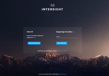
Step 2. From the Navigation tree, select the Targets and click to Claim a new Target.
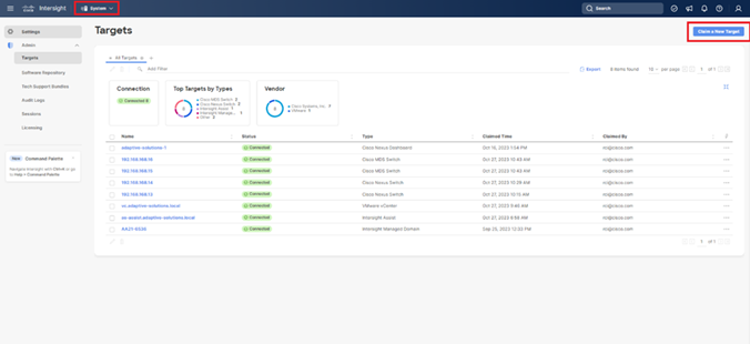
Step 3. Select categories list, select Storage as Target Type, and select Hitachi Virtual Storage Platform.
Step 4. Click Start.
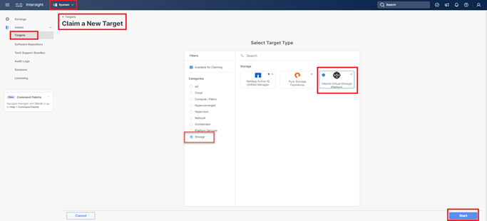
Step 5. To claim Hitachi Virtual Storage Platform Target, Enter the following:
a. From the Intersight Assist list, select the deployed Intersight Assist Virtual Appliance hostname/IP address.
b. In the Port field, enter 23451.
c. In the Username field enter the VSP storage system username.
d. In the Password field enter the VSP storage system password.
e. Enable the Secure option.
f. In the Hitachi Ops Center API Configuration Manager Address field, enter the API Configuration Manager IP address that has the registered VSP storage system.
Step 6. Click Claim.
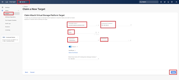
Step 7. Under Systems click Targets and All Targets to view newly connected Hitachi VSP storage with device type as Hitachi Virtual Storage Platform.
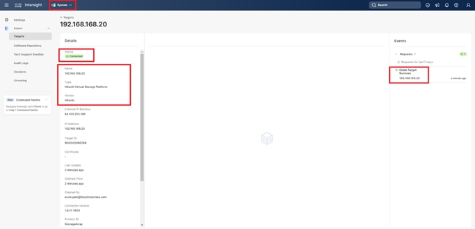
Step 8. The properties of added VSP storage systems can be found under Infrastructure Service > Storage.
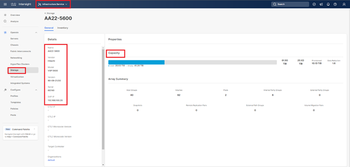
Cisco Nexus Dashboard Fabric Controller
Cisco Nexus Dashboard Fabric Controller, (NDFC formerly DCNM-SAN) can be used to monitor, configure, and analyze Cisco Fibre Channel fabrics using NDFC SAN. Cisco NDFC is deployed as an application from within the Cisco Nexus Dashboard that is installed as a virtual appliance from an OVA and is managed through a web browser. Nexus Dashboard Insights can be added to provide extended visibility into your fabric by allowing you to monitor, analyze, identify, and troubleshoot performance issues.
The installation and configuration of Nexus Dashboard can be accomplished by following the instructions within this deployment guide: https://www.cisco.com/c/en/us/td/docs/dcn/nd/2x/deployment/cisco-nexus-dashboard-deployment-guide-231.html
A single node is sufficient for NDFC, but a multi-node placement of Nexus Dashboard will be required to use Nexus Dashboard Insights. With the Nexus Dashboard installed, fabric connectivity for managed switches will need to be established as covered in this guide: https://www.cisco.com/c/en/us/td/docs/dcn/nd/2x/user-guide-23/cisco-nexus-dashboard-user-guide-231.html
Prerequisites
The following prerequisites need to be configured:
1. Licensing. Cisco NDFC includes a 60-day server-based trial license that can be used to monitor and configure Cisco MDS Fibre Channel switches and monitor Cisco Nexus switches. NDFC and Nexus Dashboard Insights can be enabled with any tier level of switch based licensing of DCN as covered in this document: https://www.cisco.com/c/en/us/products/collateral/data-center-analytics/nexus-dashboard/guide-c07-744361.html?ccid=cc001903&oid=giddnc023703
2. If SAN Analytics will be implemented, the deployment of the Nexus Dashboard should select the Data option as opposed the App option during the OVF deployment.
3. Passwords. Cisco NDFC passwords should adhere to the following password requirements:
● It must be at least eight characters long and contain at least one alphabet and one numeral.
● It can contain a combination of alphabets, numerals, and special characters.
● Do not use any of these special characters in the NDFC password for all platforms: <SPACE> " & $ % ' ^ = < > ; : ` \ | / , .*
4. NDFC SNMPv3 user on switches. Each switch (both Cisco MDS and Nexus) needs an SNMPv3 user added for NDFC to use to query and configure the switch. On each switch, enter the following command in configure terminal mode (in the example, the userid is snmpadmin):
snmp-server user snmpadmin network-admin auth sha <password> priv aes-128 <privacy-password>
5. On Cisco MDS switches, type show run. If snmpadmin passphrase lifetime 0 is present, enter username snmpadmin passphrase lifetime 99999 warntime 14 gracetime 3.
Note: Nexus Dashboard is not supported within vSphere 8 at this time and was deployed for the validation as part of the independent supporting infrastructure hosted within a vSphere 7.0U3 cluster.
Procedure 1. Install Nexus Dashboard Fabric Controller
With the Nexus Dashboard installed, the initial login screen will present the option to Configure the Basics, this can be skipped for now.
Step 1. Click Done.
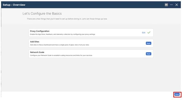
Step 2. Service IPs will need to be added to the Nexus Dashboard before an App Service can be installed, click through the starting screen, and click Go To Dashboard.
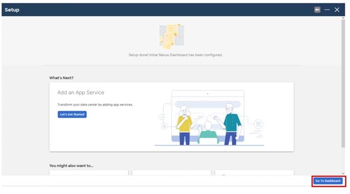
Step 3. From the drop-down list to the left of the Nexus Dashboard, choose Admin Console.
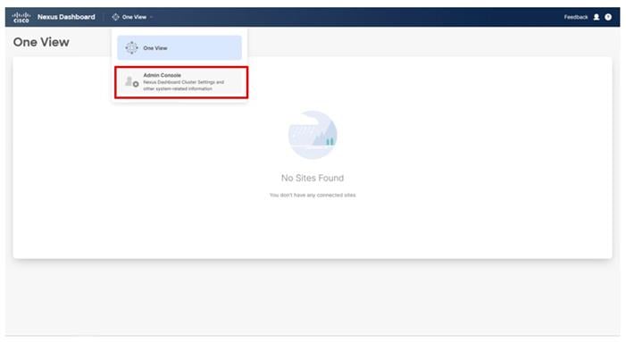
Step 4. From the System Overview go to Infrastructure > Cluster Configuration.
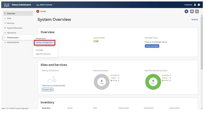
Step 5. Scroll down in the Cluster Configuration to the External Service Pools section and click the edit icon.
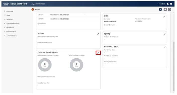
Step 6. Click Add IP Address under the Management Service IP’s.
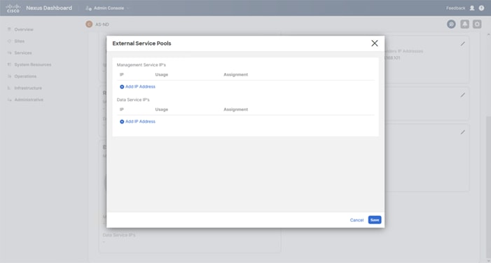
Step 7. Add IP addresses in the IB-Mgmt network on which the Nexus Dashboard was deployed. Click Save.
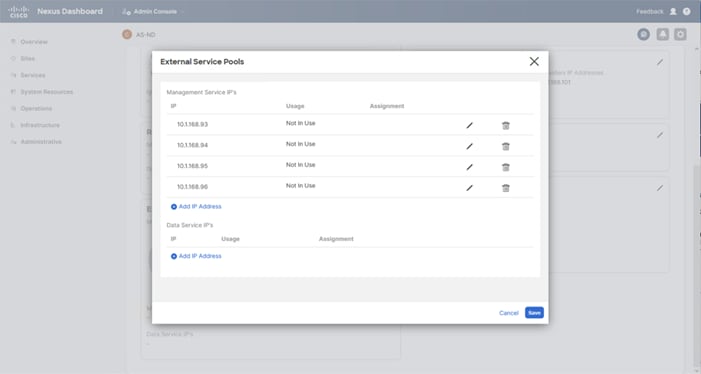
Step 8. Repeat these additions for the Data Service IP’s associated with the OOB network that the mgmt interfaces of the MDS and potentially the Nexus switches. Click Save.
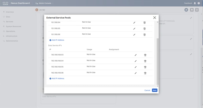
Note: The allocation of IPs in our example is four IPs for each service pool but will vary depending on the needs of services being deployed.
Step 9. Click the edit icon in the Routes section.
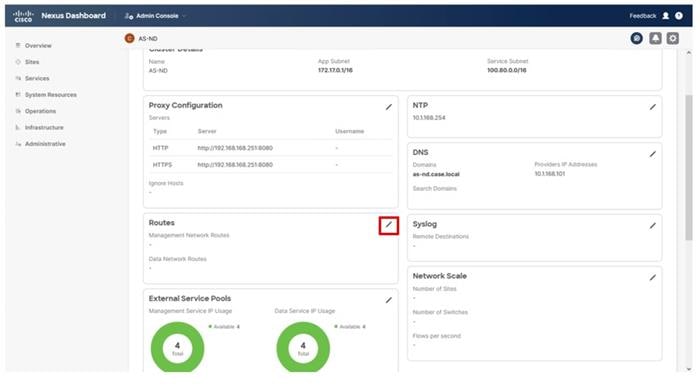
Step 10. Click Add Management Network Routes.
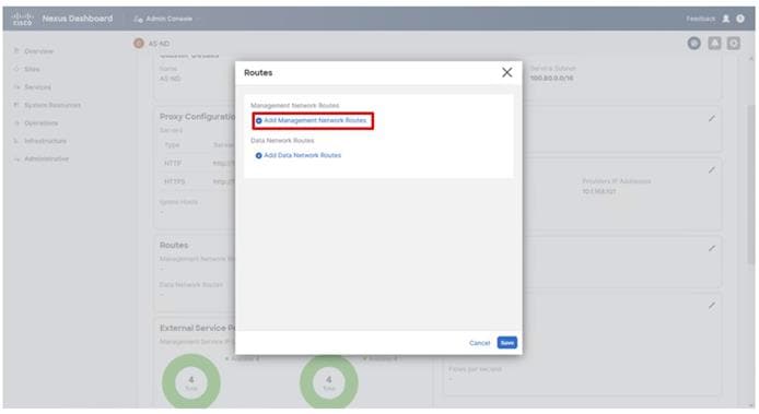
Step 11. Repeat the addition for the appropriate Data Network gateway and click Save.
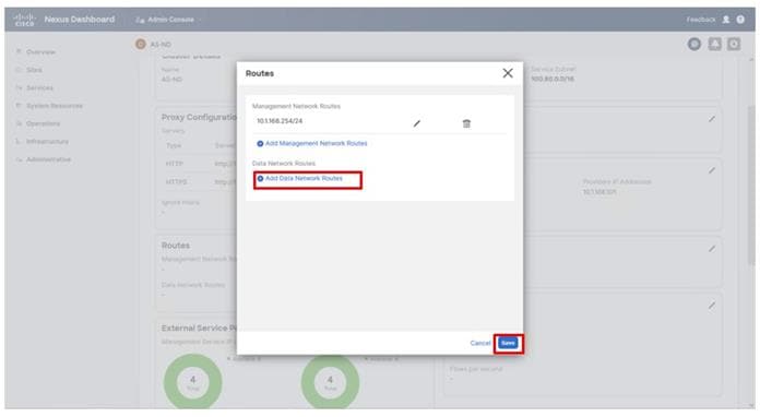
Step 12. Click Services, then click Install Services.
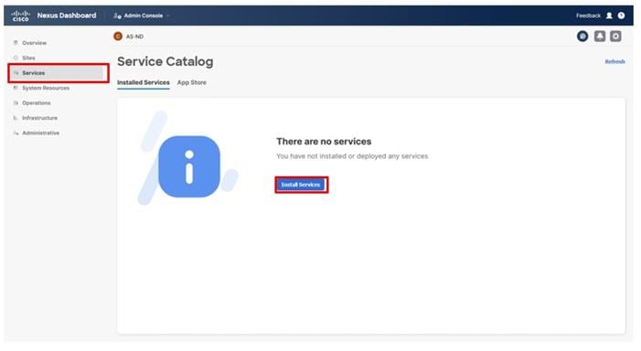
Step 13. Click CISCO DC App Center to access available apps.
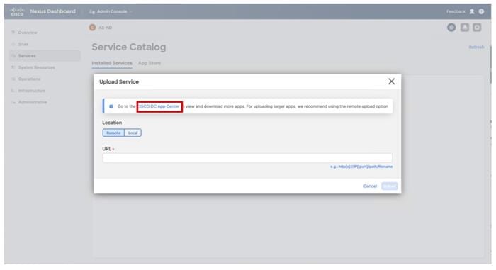
Step 14. Within the window that is open for the App Center, choose the ND option from the All Platforms drop-down list.
Step 15. Choose the 2.3.2 option From the All Platform Versions drop-down list.
Step 16. Click the Download icon within the Nexus Dashboard Fabric Controller box.
Step 17. Log in to id.cisco.com with CCO credentials and click Agree and Download within the License Agreement pop-up window.
Step 18. Return to the Nexus Dashboard window, click Local in the Upload Service dialogue window, and click Browse… to select the downloaded .nap application file for NDFC.
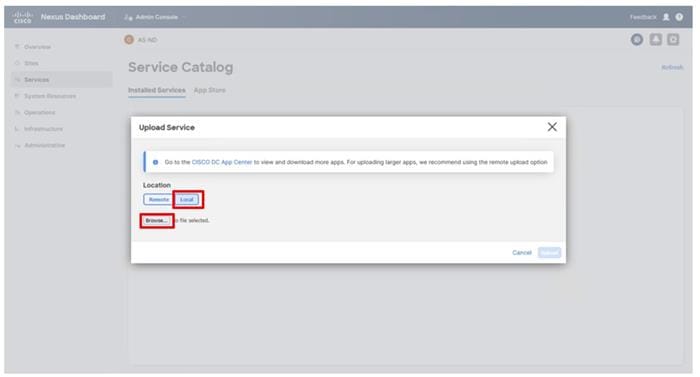
Step 19. Click Upload.
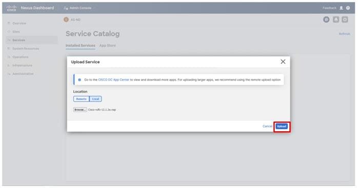
Step 20. After the upload and installation has completed, click Enable.
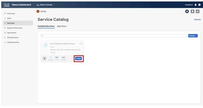
Procedure 2. Configure Nexus Dashboard Fabric Controller
Step 1. Click Open or choose the option Fabric Controller.
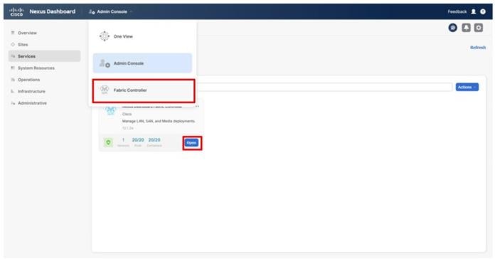
Step 2. Click the SAN Controller option.
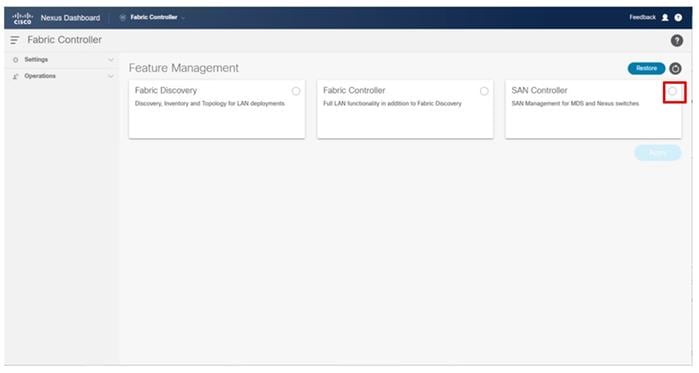
Step 3. Confirm Cisco as the OEM vendor.
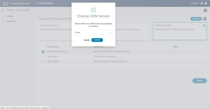
Step 4. Select the Performance Monitoring and VMM Visualizer features and click Apply.
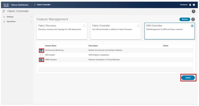
Step 5. The status will display Started when complete and the page will need to be reloaded to continue.
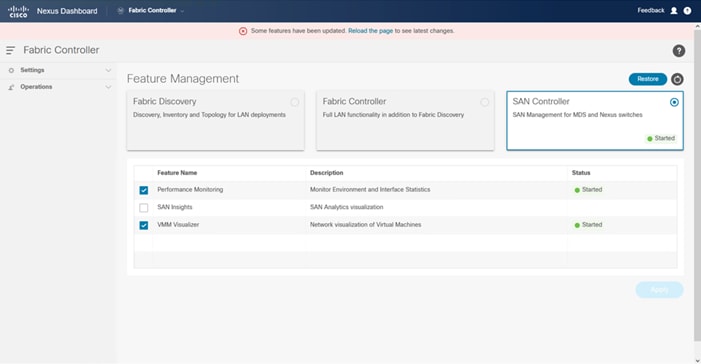
Step 6. Expand Virtual Management and click Virtual Infrastructure Manager.
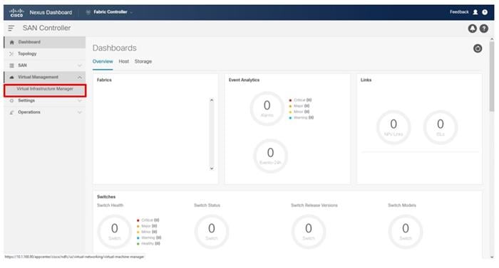
Step 7. Select Actions > Add Instance.
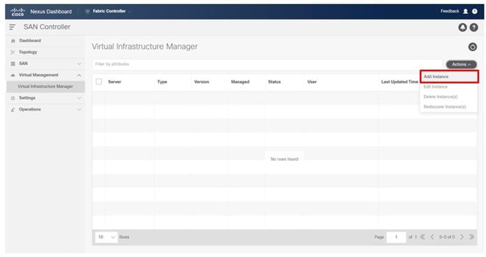
Step 8. From the Add Instance pop-up window, choose vCenter
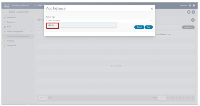
Step 9. Provide the vCenter IP address or FQDN, and the appropriate Username and Password for access. Click Add.

Step 10. Select SAN and click the Fabrics option from the expanded menu.
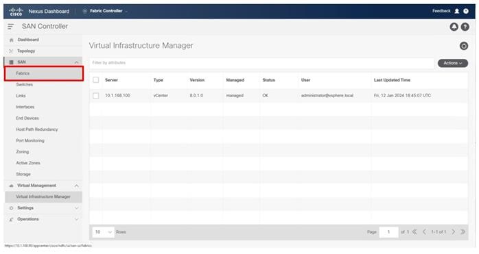
Step 11. Click Actions and choose Add Fabric from the drop-down list.
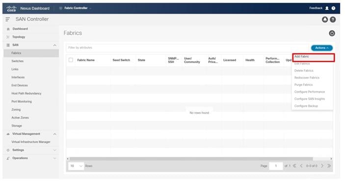
Step 12. Specify the Fabric Name for the A side Fabric, enter the IP address of the A side MDS, set the Authentication/Privacy to SHA_AES, provide the snmp user created on the switches, and click Add.
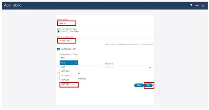
Step 13. Click OK upon completion and repeat steps 31-32 for Fabric-B.
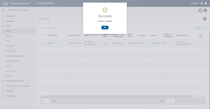
With NDFC SAN in place, the SAN resources can be seen from the Dashboard view:
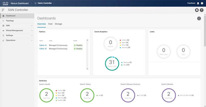
The management and operation functions available include SAN zoning, image management of the MDS switches, Device Manager, and Backup/Restore functions.
This chapter contains the following:
● vSphere Cluster Image Update
● Add Remaining Hosts to vCenter
● Hitachi Storage Provider for VMware vCenter Initial Configuration
● Storage Policy Based Management (SPBM) for VMFS LDEVs
● Host Image and vSphere Configuration Profiles
● vSphere Additional Finishing Steps
This chapter provides detailed instructions for installing VMware ESXi 8.0U1 within Adaptive Solutions. On successful completion of these steps, multiple ESXi hosts will be provisioned and ready to be added to VMware vCenter.
Several methods exist for installing ESXi in a VMware environment. These procedures focus on how to use the built-in keyboard, video, mouse (KVM) console and virtual media features in Cisco Intersight to map remote installation media to individual servers.
Procedure 1. Download VMware ESXi ISO
Step 1. Click the following link: Cisco Custom Image for ESXi 8.0 U1 Install CD.
Note: You will need a VMware user id and password on vmware.com to download this software.
Step 2. Download the .iso file.
Procedure 2. Log into Cisco Intersight and Access KVM
The Cisco Intersight KVM enables the administrators to begin the installation of the operating system (OS) through remote media. It is necessary to log into the Cisco Intersight to access the UCS Server KVM connections.
Step 1. Log into Cisco Intersight.
Step 2. From the main menu, go to Infrastructure Service > Servers.
Step 3. Find the Server with the desired Server Profile assigned and click “…” to see more options
Step 4. Click Launch vKVM.
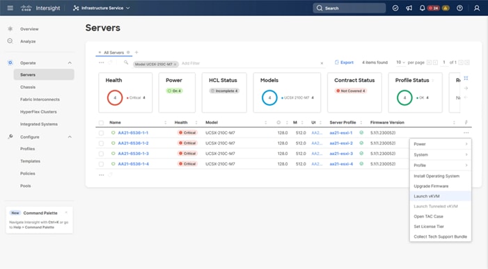
Step 5. Follow the prompts and ignore certificate workings (if any) and launch the HTML5 KVM console.
Step 6. Repeat steps 1 - 5 to launch the vKVM console for all the ESXi servers.
Procedure 3. Prepare the Server for the OS Installation
Note: Follow these steps on each ESXi host.
Step 1. In the KVM window, click Virtual Media > vKVM-Mapped vDVD.
Step 2. Browse and select the ESXi installer ISO image file downloaded in Procedure 1 Download VMware ESXi ISO (VMware-ESXi-8.0.U1a-21813344-Custom-Cisco-4.3.1-a).
Step 3. Click Map Drive.
Step 4. Go to Power > Reset System and Confirm to reboot the server if the server is showing a shell prompt. If the server is shut down, click Power > Power On System.
Step 5. Monitor the server boot process in the KVM. The server should find the boot LUNs and begin to load the ESXi installer.
Note: If the ESXi installer fails to load because the software certificates cannot be validated, reset the server, and when prompted, press F2 to go into BIOS and set the system time and date to current. The ESXi installer should load properly.
Procedure 4. Install VMware ESXi onto the bootable LUN of the UCS Servers
Note: Follow these steps on each host.
Step 1. After the ESXi installer is finished loading (from the last step), press Enter to continue with the installation.
Step 2. Read and accept the end-user license agreement (EULA). Press F11 to accept and continue.
Note: It may be necessary to map function keys as User Defined Macros under the Macros menu in the KVM console.
Step 3. Select the Hitachi VSP boot LUN that was previously set up as the installation disk for ESXi and press Enter to continue with the installation.
Step 4. Select the appropriate keyboard layout and press Enter.
Step 5. Enter and confirm the root password and press Enter.
Step 6. The installer issues a warning that the selected disk will be repartitioned. Press F11 to continue with the installation.
Step 7. After the installation is complete, press Enter to reboot the server. The ISO will be unmapped automatically.
Procedure 5. Add the Management Network for each VMware Host
Note: This is required for managing the host. To configure the ESXi host with access to the management network, follow these steps on each ESXi host.
Step 1. After the server has finished rebooting, in the UCS KVM console, press F2 to customize VMware ESXi.
Step 2. Log in as root, enter the password set during installation, and press Enter to log in.
Step 3. Use the down arrow key to choose Troubleshooting Options and press Enter.
Step 4. Select Enable ESXi Shell and press Enter.
Step 5. Select Enable SSH and press Enter.
Step 6. Press Esc to exit the Troubleshooting Options menu.
Step 7. Select the Configure Management Network option and press Enter.
Step 8. Select Network Adapters and press Enter. Ensure the vmnic numbers align with the numbers under the Hardware Label (for example, vmnic0 and 00-vSwitch0-A). If these numbers do not align, note which vmnics are assigned to which vNICs (indicated under Hardware Label).
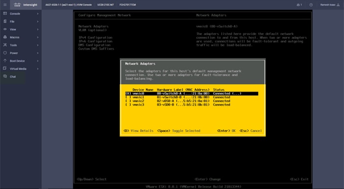
Step 9. Arrow down to select vmnic1 and press the spacebar to select it.
Step 10. Press Enter.
Note: In the UCS Configuration portion of this document, the IB-MGMT VLAN was set as the native VLAN on the 00-vSwitch0-A and 01-vSwitch0-B vNICs. Because of this, the IB-MGMT VLAN should not be set here and should remain Not set.
Step 11. Select IPv4 Configuration and press Enter.
Note: When using DHCP to set the ESXi host networking configuration, setting up a manual IP address is not required.
Step 12. Select the Set static IPv4 address and network configuration option by using the arrow keys and space bar.
Step 13. Under IPv4 Address, enter the IP address for managing the ESXi host.
Step 14. Under Subnet Mask, enter the subnet mask.
Step 15. Under Default Gateway, enter the default gateway.
Step 16. Press Enter to accept the changes to the IP configuration.
Step 17. Select the IPv6 Configuration option and press Enter.
Step 18. Using the spacebar, choose Disable IPv6 (restart required) and press Enter.
Step 19. Select the DNS Configuration option and press Enter.
Note: If the IP address is configured manually, the DNS information must be provided.
Step 20. Using the spacebar, select the following DNS server addresses and hostname:
● Under Primary DNS Server, enter the IP address of the primary DNS server.
● Optional: Under Alternate DNS Server, enter the IP address of the secondary DNS server.
● Under Hostname, enter the fully qualified domain name (FQDN) for the ESXi host.
● Press Enter to accept the changes to the DNS configuration.
● Press Esc to exit the Configure Management Network submenu.
● Press Y to confirm the changes and reboot the ESXi host.
Procedure 6. (Optional) Reset VMware ESXi Host VMkernel Port MAC Address
Note: By default, the MAC address of the management VMkernel port vmk0 is the same as the MAC address of the Ethernet port it is placed on. If the ESXi host’s boot LUN is remapped to a different server with different MAC addresses, a MAC address conflict will exist because vmk0 will retain the assigned MAC address unless the ESXi System Configuration is reset.
Step 1. From the ESXi console menu main screen, select Macros > Static Macros > Ctrl + Alt + F’s > Ctrl + Alt + F1 to access the VMware console command line interface.
Step 2. Log in as root.
Step 3. Type “esxcfg-vmknic –l” to get a detailed listing of interface vmk0. vmk0 should be a part of the “Management Network” port group. Note the IP address and netmask of vmk0.
Step 4. To remove vmk0, type esxcfg-vmknic –d “Management Network”.
Step 5. To re-add vmk0 with a random MAC address, type esxcfg-vmknic –a –i <vmk0-ip> -n <vmk0-netmask> “Management Network”.
Step 6. Verify vmk0 has been re-added with a random MAC address by typing esxcfg-vmknic –l.
Step 7. Tag vmk0 as the management interface by typing esxcli network ip interface tag add -i vmk0 -t Management.
Step 8. When vmk0 was re-added, if a message pops up saying vmk1 was marked as the management interface, type esxcli network ip interface tag remove -i vmk1 -t Management.
Step 9. Press Ctrl-D to log out of the ESXi console.
Step 10. Select Macros > Static Macros > Ctrl + Alt + F’s > Ctrl + Alt + F2 to return to the VMware ESXi menu.
VMware ESXi Configuration
With the UCS servers finished with their ESXi installation and basic configuration, they can now be added to the vCenter.
Note: In the validated environment, the vCenter is deployed within an existing management cluster independent of the Adaptive Solutions VSI environment. The vCenter Appliance could be deployed within the VSI itself with a first host that is configured through the vSphere web client and had the VSP VMFS datastores associated to it, but that is not covered in our deployment example.
Procedure 1. Add deployed ESXi instance to the vCenter
Step 1. Open a web browser and navigate to the vCenter server.
Step 2. Select the top left tribar symbol to open the menu options and select the Inventory option.
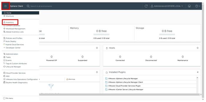
Step 3. If there is not an established Datacenter object within the vCenter, right-click the vCenter on the left and select New Datacenter… provide the Datacenter with an appropriate name.
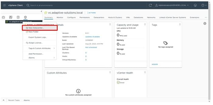
Step 4. Right-click the Datacenter object and select the New Cluster… option.
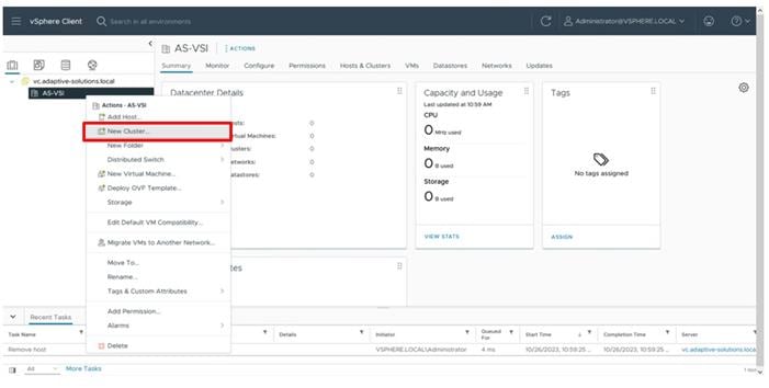
Step 5. Provide a name for the Cluster, enable vSphere DRS and vSphere HA, select Import image from a new host, check the box for Manage configuration at a cluster level, and click NEXT.
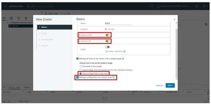
Step 6. Enter the IP or FQDN of the first host, enter root for the username, and provide the password specified during initial setup. Click FIND HOST.
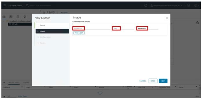
Step 7. Click Yes past the Security Alert if prompted.
Step 8. Confirm the host is found correctly. Leave Also move select host to cluster selected and click Next.
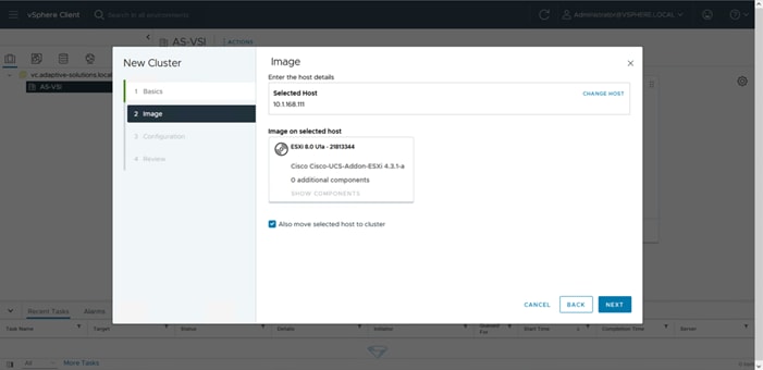
Step 9. Click NEXT past the Configuration screen dialogue summary. Confirm the cluster options and image setup within Review and click FINISH.
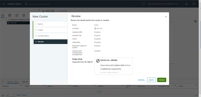
Note: The added ESXi host will have Warnings that the ESXi Shell and SSH have been enabled. These warnings can be suppressed. The host will also have a TPM Encryption Key Recovery alert that can be acknowledged and reset to green.
VMware ESXi Configuration for the first ESXi Host
Procedure 1. Set Up VMkernel Ports and Virtual Switch
Step 1. Select the added host from within the new cluster, go to Configure > Networking > Virtual Switches.
Step 2. Click EDIT.
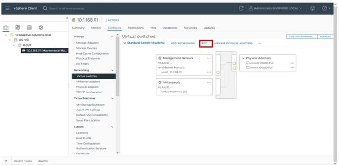
Step 3. Set the MTU to 9000.
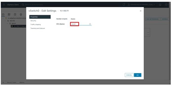
Step 4. Select Teaming and failover and confirm that both vmnic0 and vmnic1 are shown as Active adapters for vSwitch0, adjust adapters with MOVE UP and MOVE DOWN options if needed. Click OK.
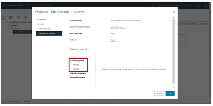
Step 5. Click the … next to the VM Network port group and select Edit Settings.
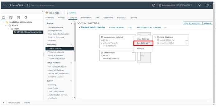
Step 6. Change the name of VM Network to IB-Mgmt Network and click Teaming and failover.
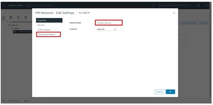
Step 7. Select the Override checkbox, select the vmnic1 adapter and click the MOVE DOWN option. Click OK.
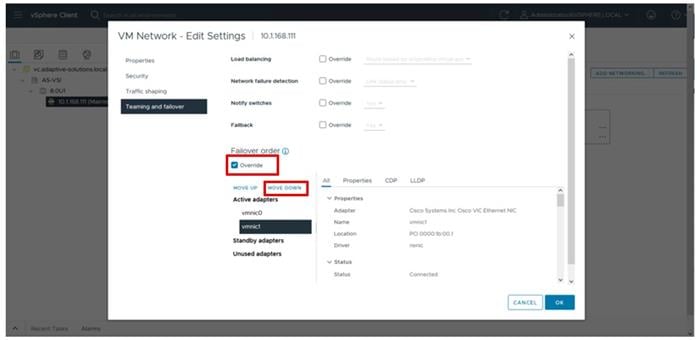
Step 8. Click the … next to the Management Network port group and select Edit Settings.
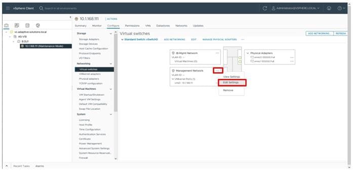
Step 9. Click Teaming and failover.
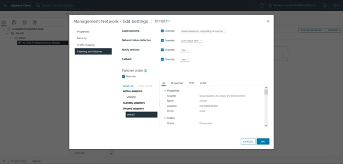
Step 10. Select vmnic1 and move it to the Standby adapters category within Failover order and click OK.
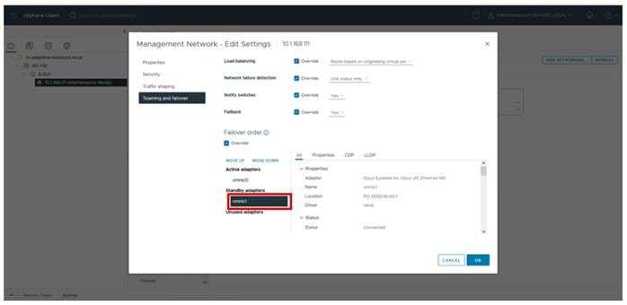
The properties for vSwitch0 appear as shown below:
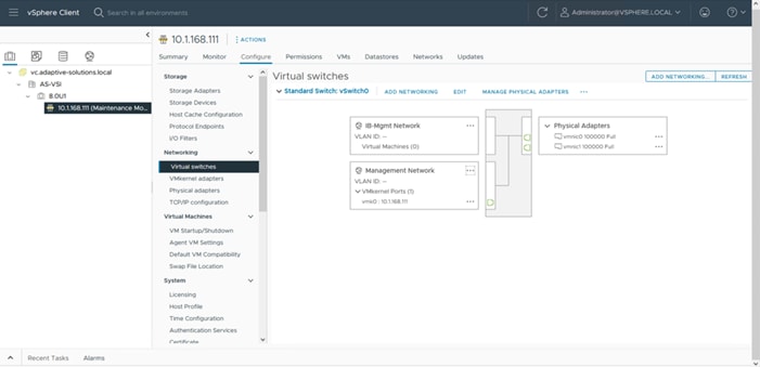
Procedure 2. Create VMware vDS for vMotion and Application Traffic
The VMware vDS setup will create a single vDS for vMotion and Application traffic.
To configure the first VMware vDS, follow these steps:
Step 1. Right-click the AS-VSI datacenter and select Distributed Switch > New Distributed Switch…
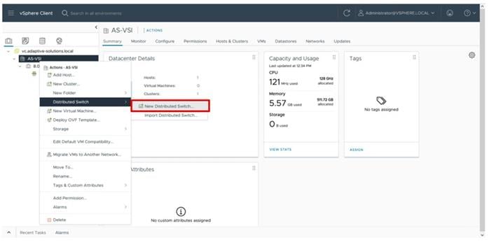
Step 2. Provide a name for the distributed switch and click NEXT.
Step 3. Leave 8.0.0 selected for the distributed switch version and click NEXT.
Step 4. Lower the Number of uplinks from 4 to 2 and provide Port group name for the default port group to align with the Application traffic. Click NEXT.
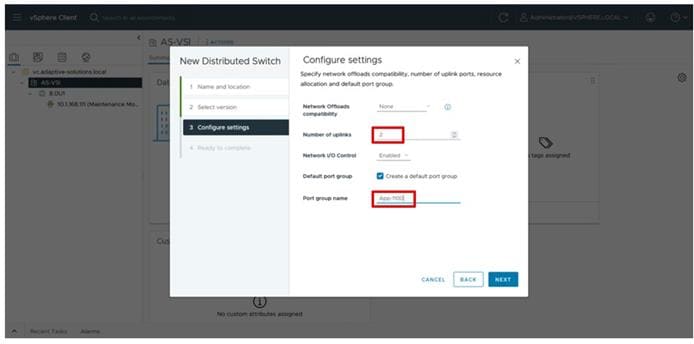
Step 5. Review the settings for the distributed switch and click FINISH.
Step 6. Click the Networking icon of the left-side menu and right-click the newly created distributed switch. Under Actions select Settings > Edit Settings… .
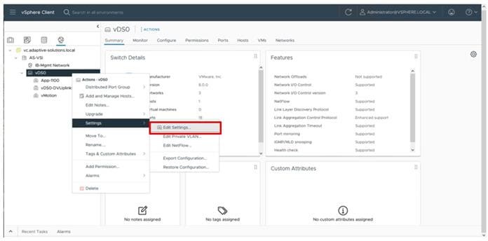
Step 7. Select the Advanced tab and change the MTU from 1500 to 9000. Click OK.
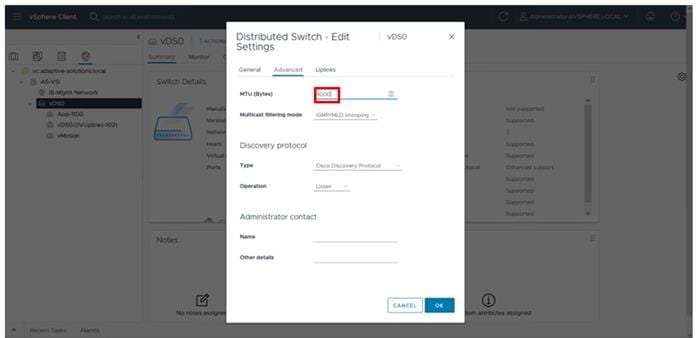
Procedure 3. Create vMotion distributed port group
Step 1. Right-click the newly created distributed switch. Within Actions, select Distributed Port Group > New Distributed Port Group… .
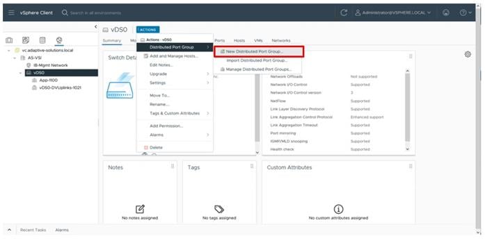
Step 2. Provide a name for the vMotion distributed port group and click NEXT.
Step 3. Choose VLAN from the VLAN type drop-down list and specify the appropriate VLAN for vMotion. Select the Customize default policies configuration checkbox and click NEXT.
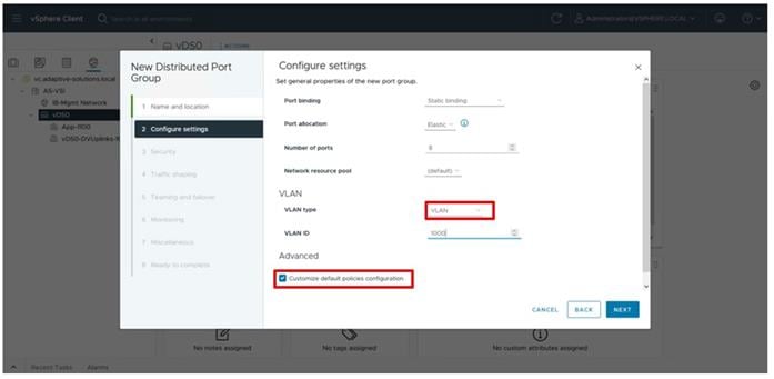
Step 4. Click NEXT through the Security and Traffic shaping dialogue screens.
Step 5. Within Teaming and failover, select Uplink 1 and click MOVE DOWN twice to have it set as a standby link. Click NEXT.
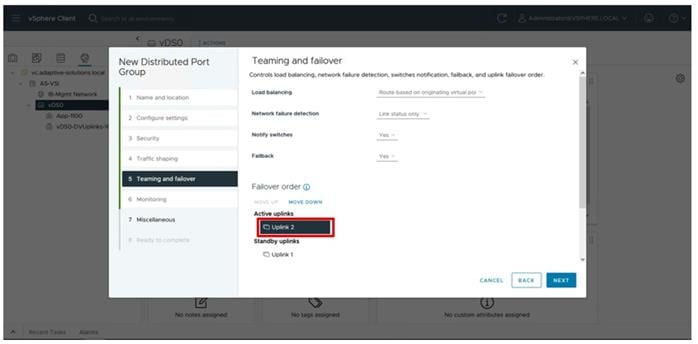
Step 6. Click NEXT through the Monitoring and Miscellaneous dialogue screens, review the settings presented within Ready to complete, and click FINISH to create the distributed port group.
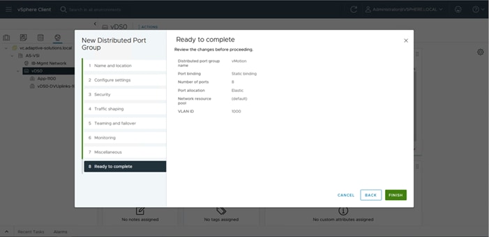
Step 7. Repeat steps 1-6 for each VM application network taking note of desired teaming and failover, making both uplinks active if there is no path priority.
Procedure 4. Add ESXi host to the vDS
Step 1. Select the distributed switch, right-click it and select the Add and Manage Hosts… option.
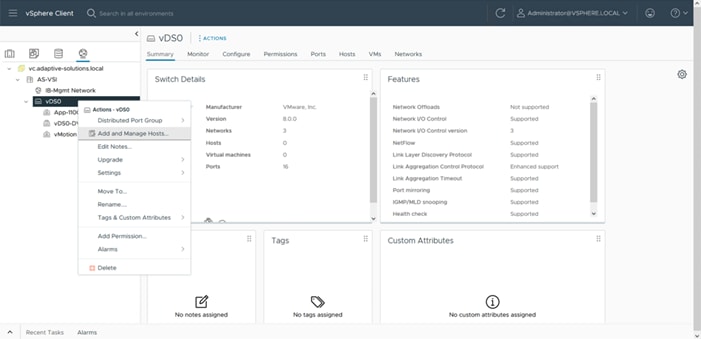
Step 2. Leave Add hosts selected and click NEXT.
Step 3. Select the first ESXi host that was previously added to vCenter and click NEXT.
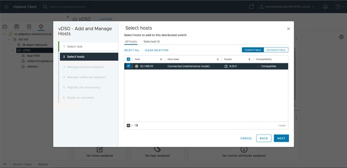
Step 4. Specify vmnic2 to be Uplink 1 and vmnic3 to be Uplink 2, and then click NEXT.
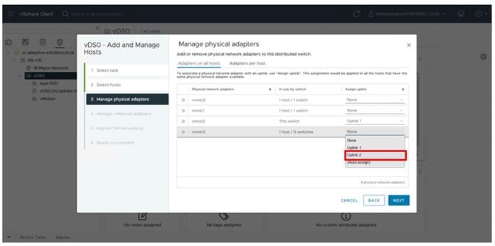
Step 5. Click NEXT past the Manage VMkernel adapters and Migrate VM networking dialogue screens. Review the summary within the Ready to compete screen and then click FINISH.
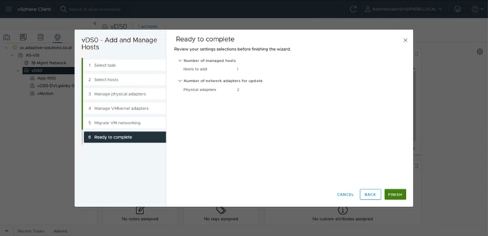
Procedure 5. Add vMotion vmkernel to the first ESXi host
Step 1. Select the vMotion distributed port group, right-click it and select the Add VMkernel Adapters… option.
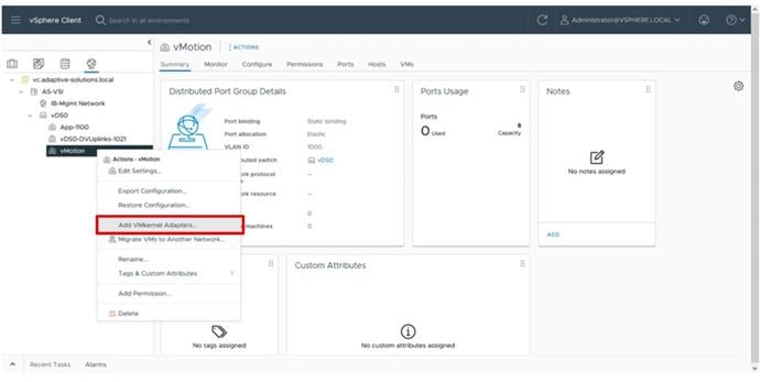
Step 2. Select the first ESXi host and click NEXT.
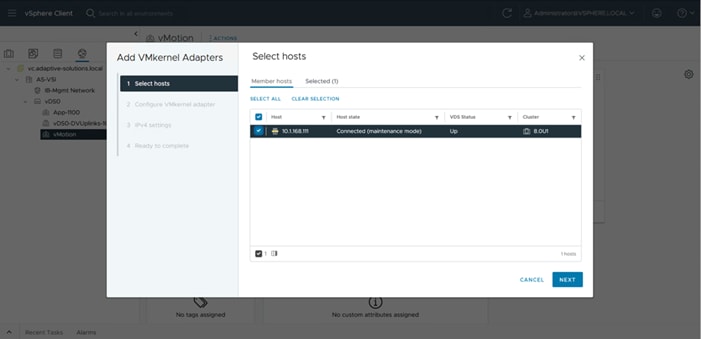
Step 3. Select vMotion from the TCP/IP stack drop-down list. Click NEXT.
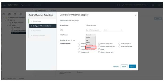
Step 4. Select Use static IPV4 settings and provide an IP and netmask for the VMkernel. Click NEXT.
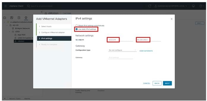
Step 5. Review the summary within Ready to complete and click FINISH.
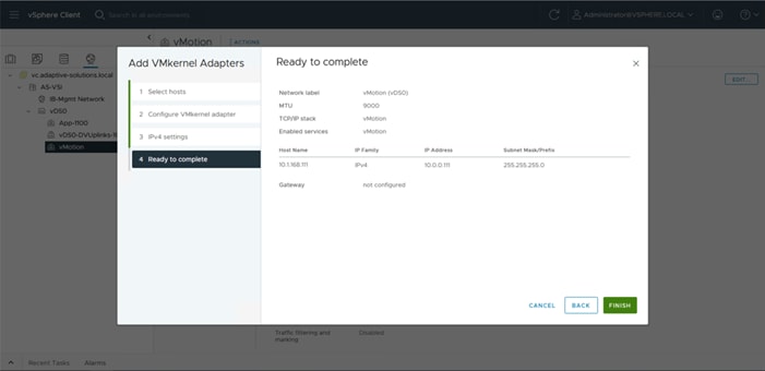
Procedure 6. Configure settings on the ESXi host
Step 1. Select the Hosts and Clusters icon, expand the datacenter and cluster to find the first ESXi host. Select Configure > System > Time Configuration.
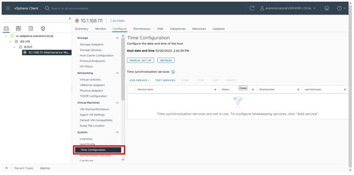
Step 2. Select MANUAL SET-UP if the time is not correct and adjust it. From the ADD SERVICE drop-down list and select the Network Time Protocol option.
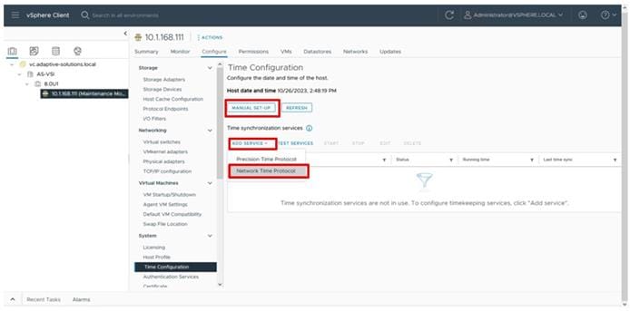
Step 3. Specify the appropriate IP/FQDN(s) for NTP server(s). Click OK.
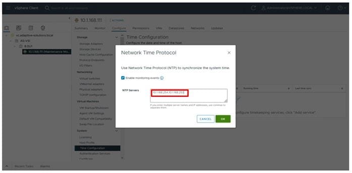
Procedure 7. Configure Host Power Policy
Note: Implementing this policy is recommended in the Performance Tuning Guide for Cisco UCS M7 Servers: https://www.cisco.com/c/en/us/products/collateral/servers-unified-computing/ucs-b-series-blade-servers/ucs-m7-platforms-wp.html#AdditionalBIOSrecommendationsforenterpriseworkloads for maximum VMware ESXi performance. This policy can be adjusted based on your requirements.
Step 1. Within the first ESXi host, select Configure > Hardware > Overview and find Power Management at the bottom of the Overview section. Click EDIT POWER POLICY.
Step 2. Select Balanced from the options and click OK.
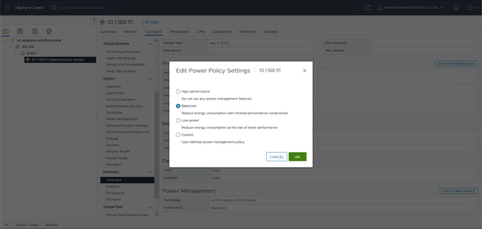
Procedure 1. UCS Tools Update
The UCS Tools VIB for ESXi allows IPMI communication over the CISCO IMC of the underlying Cisco UCS server to communicate vSphere relevant host information to Intersight and UCSM managed placements.
Step 1. Download the UCS Tools VIB for ESXi 8.0 from https://software.cisco.com/download/home/286305108/type/286323573/release/1.3.3
Step 2. Go to Lifecycle Manager from the main vCenter left-hand menu, click ACTIONS and choose the Import Updates option.
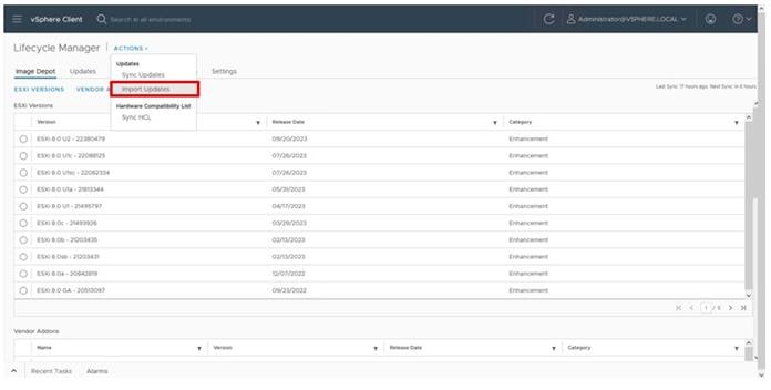
Step 3. Click Browse within the pop-up window and navigate to the downloaded location of the UCS Tools VIB package.
The uploaded VIB is now available from Edit Image for the cluster within the ADD COMPONENTS within the Independent components and Vendor Addon Components selection.
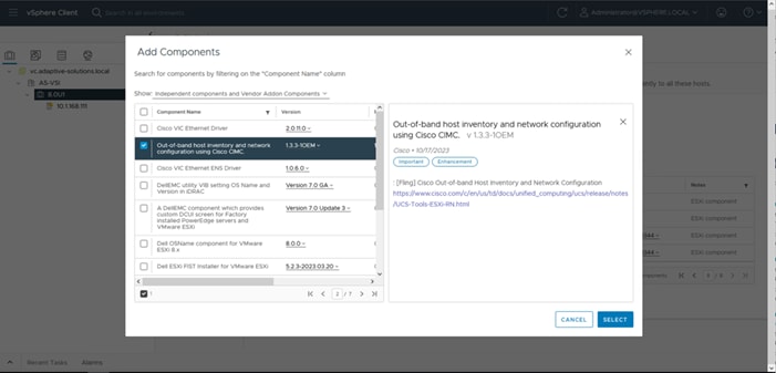
Procedure 2. Hardware Support Manager Configuration
Step 1. Select the cluster for the VSI servers and click the Updates tab, then click EDIT within the Image section.
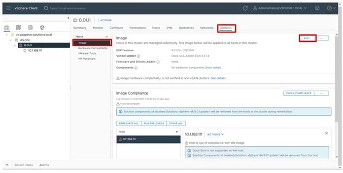
Step 2. Select the ESXi Version from the drop-down list and select the 8.0 U1c version that will reflect the addition of the vSphere 8.0U1c patch.
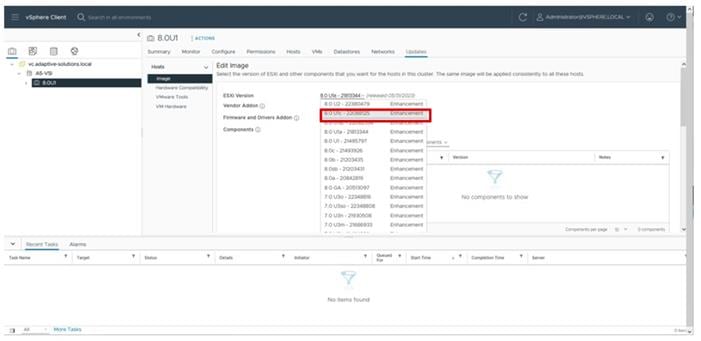
Step 3. Click SELECT from Firmware and Drivers Addon. From the Select the hardware support manager drop-down list, select the Cisco Intersight HSM @[the deployed Intersight Assist name].
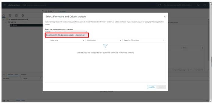
Step 4. Find the desired firmware to set for the servers and click SELECT.
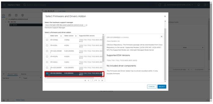
Step 5. Click Show Details from Components.
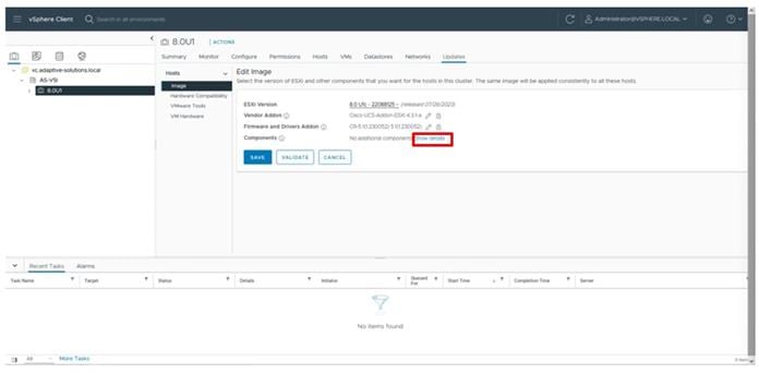
Step 6. From the Show drop-down list, select All components.
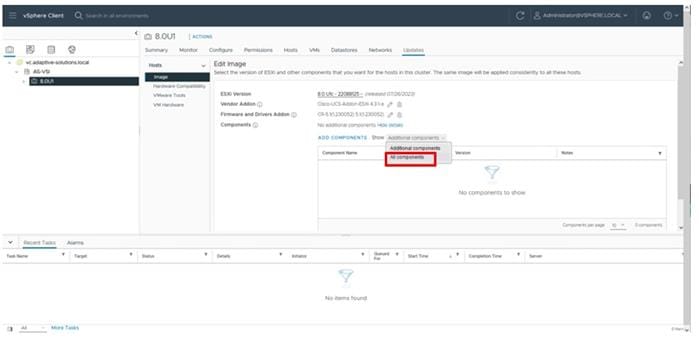
Step 7. Find the Cisco Native Ethernet Driver, the Cisco UCS VIC Native fNIC Driver, and the Out-of-band host inventory and network configuration using Cisco CIMC (UCS Tools for ESXi) selections and from the drop-down list for each to select the recommended drivers (nenic 2.0.11.0, nfnic 5.0.0.41, 1.3.3-1OEM).
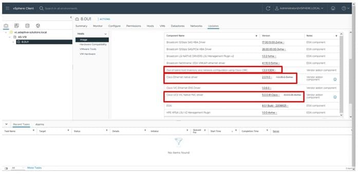
Step 8. With the appropriate drivers selected, click VALIDATE and then click SAVE.
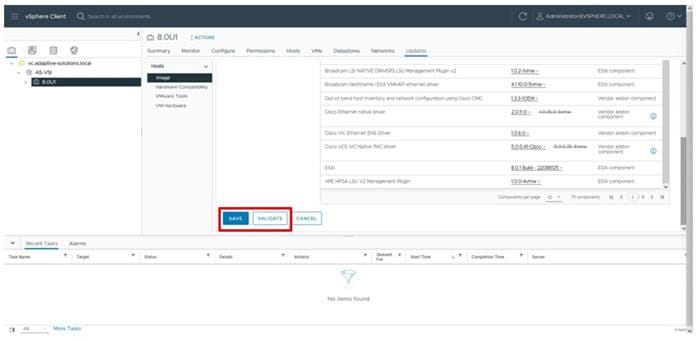
Step 9. Select the added host and go to Updates > Hosts > Image and then click View Image.
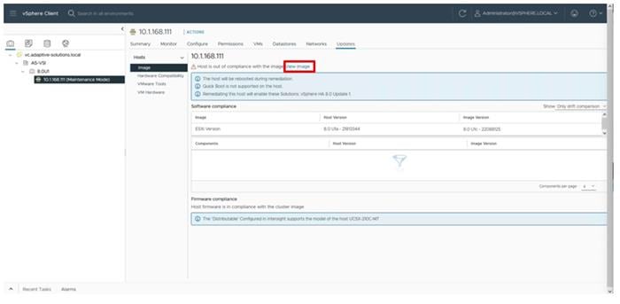
Step 10. With the host selected in the Image Compliance section, click RUN PRE-CHECK.
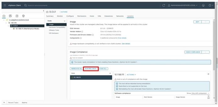
Step 11. With the RUN PRE-CHECK, cleared, click REMEDIATE ALL.
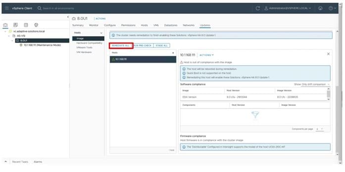
Step 12. Review the Impact summary and click START REMEDIATION.
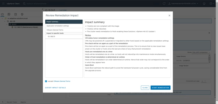
The host will be patched to 8.0 U1c and the VIBs will be installed, after which the host will automatically reboot after remediation.
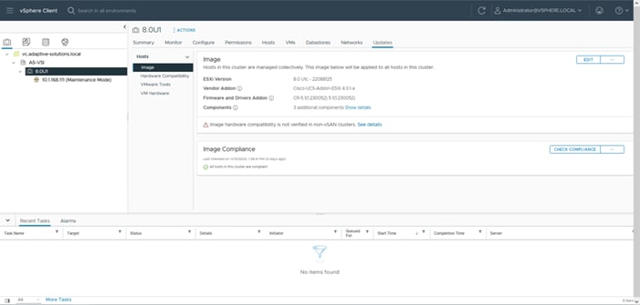
Add Remaining Hosts to vCenter
This procedure details the steps to add and configure an ESXi host in vCenter.
Procedure 1. Add the ESXi Hosts to vCenter
Step 1. From the Home screen in the VMware vCenter HTML5 Interface, select Hosts and Clusters.
Step 2. Right-click the cluster and click Add Hosts.
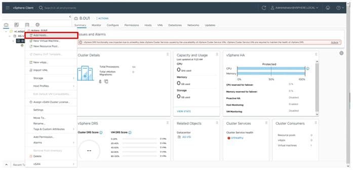
Step 3. In the IP address or FQDN field, enter either the IP address or the FQDN name of the configured VMware ESXi host. Enter the user id (root) and associated password. If more than one host is being added, add the corresponding host information, optionally selecting “Use the same credentials for all hosts.” Click NEXT.
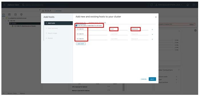
Step 4. Select all hosts being added and click OK to accept the thumbprint(s) when prompted with the Security Alert pop-up.
Step 5. Review the host details and click NEXT to continue.
Step 6. Leave Don’t import an image selected and click NEXT.
Step 7. Review the configuration parameters and click FINISH to add the host(s).
Note: The added ESXi host(s) will be placed in Maintenance Mode and will have Warnings that the ESXi Shell and SSH have been enabled. These warnings can be suppressed. The TPM Encryption Recovery Key Backup Alarm can also be Reset to Green.
Procedure 2. Add additional hosts to vDS
The additional host will need to join the vDS for vMotion and application traffic.
Step 1. Select the Network icon from the left side menu, right-click the created vDS and select the Add and Manage Hosts… option.
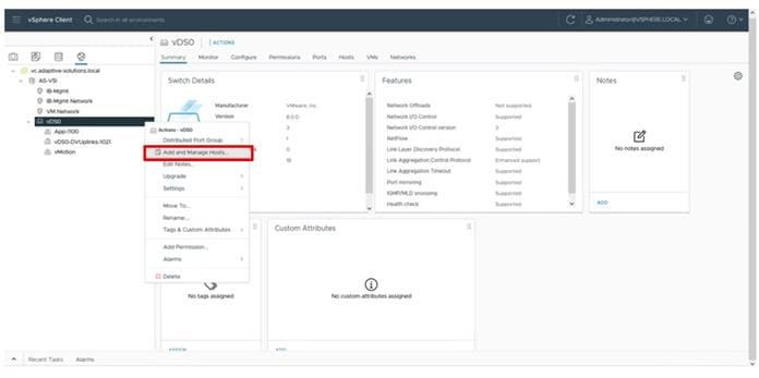
Step 2. With Add hosts selected click NEXT.
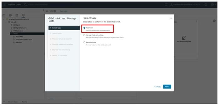
Step 3. Select all additional hosts and click NEXT.
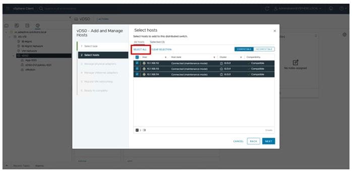
Step 4. Assign Uplink 1 to vmnic2 and Uplink 2 to vmnic3 and then click NEXT.
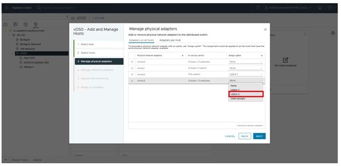
Step 5. Click NEXT through Manage VMkernel adapters and Migrate VM networking.
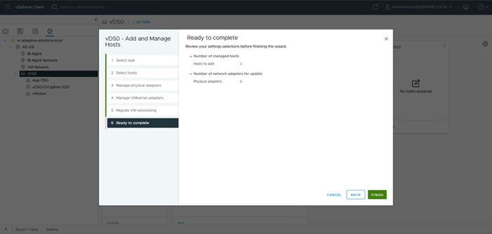
Step 6. Confirm the host addition numbers match and click FINISH.
Step 7. Right-click the vMotion vDS port group and click the Add VMkernel Adapters… option.
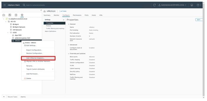
Step 8. Select the added hosts and click NEXT.
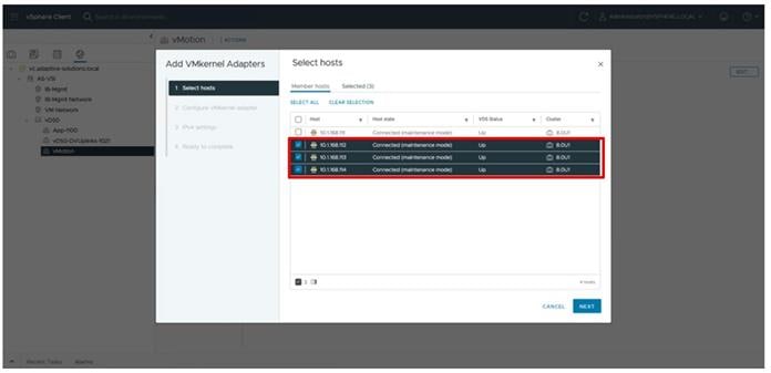
Step 9. From the drop-down list for TCP/IP stack, choose vMotion and click NEXT.
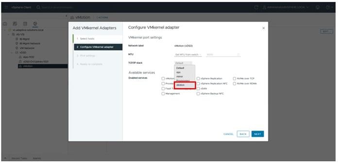
Step 10. Select the Use static IPv4 settings option and provide vMotion IP and netmask information for each host. Click NEXT.
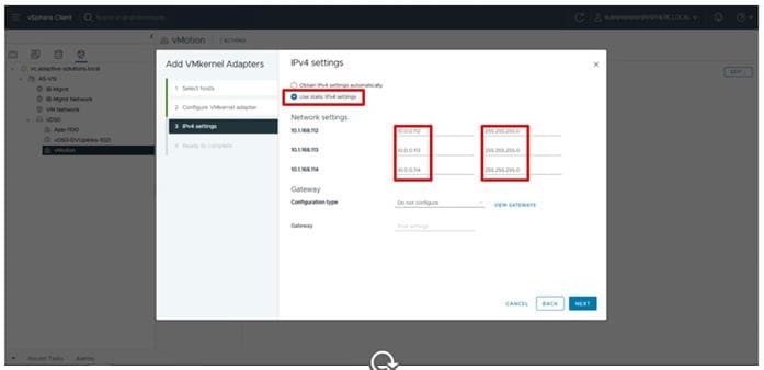
Step 11. Click FINISH.
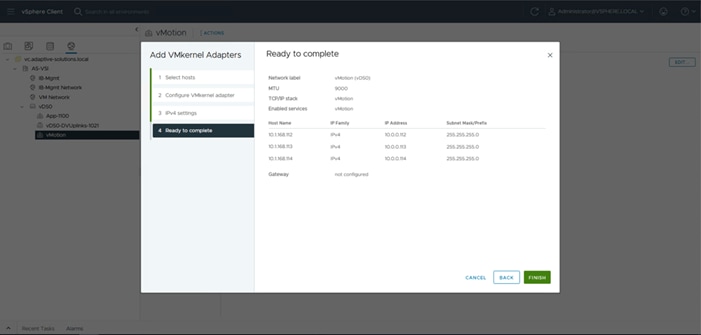
Procedure 3. Image Reconciliation
Step 1. Click Updates > Hosts > Image for the VSI cluster and select RUN PRE-CHECK.
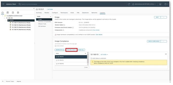
Step 2. After the pre-check resolves, click REMEDIATE ALL.
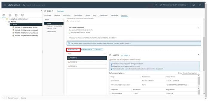
Step 3. Click START REMEDIATION.
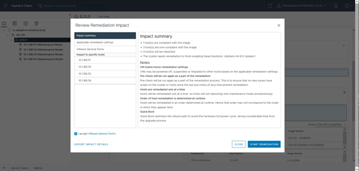
Step 4. Confirm the remediation has completed successfully.
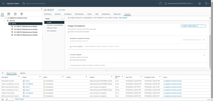
Procedure 1. Add FC-SCSI Datastores
Step 1. Select the first ESXi host, right-click and select Storage > New Datastore… .
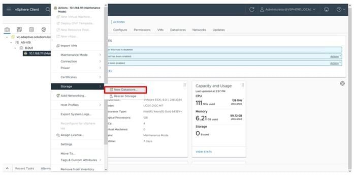
Step 2. Leave VMFS selected for the type and click NEXT.
Step 3. Select the allocated LUN and provide an appropriate name and click NEXT.
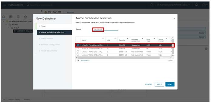
Step 4. Leave VMFS 6 selected and click NEXT.
Step 5. Leave the default options to use all storage within the Partition configuration screen and click NEXT.
Step 6. Review the summary within the Ready to complete dialogue and click FINISH.
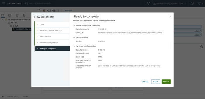
Step 7. Repeat steps 1-6 for any additional datastores.
Procedure 2. Configure FC-NVMe Datastores
Step 1. Select the first host added within the cluster and click Configure > Storage > Storage Devices.
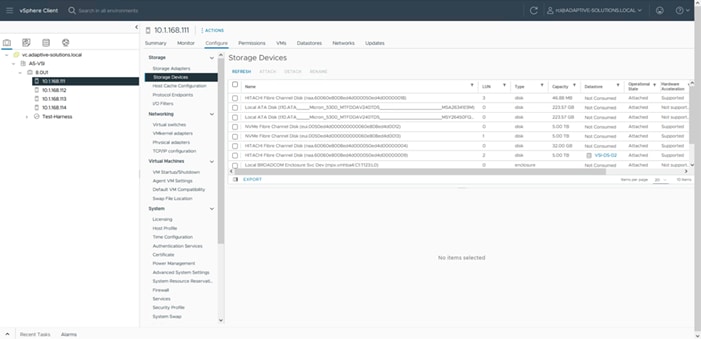
Step 2. Confirm that the NVMe Fibre Channel Disk devices are listed.
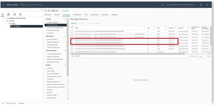
Step 3. Select the first NVMe Fibre Channel Disk, then select Paths. Verify that all paths have a status of Active (I/O).
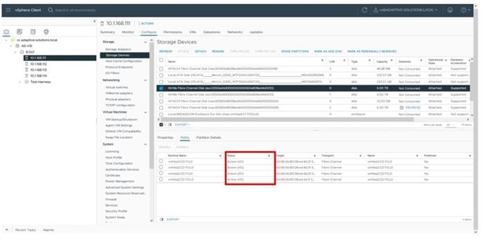
Step 4. Repeat Step 3 for any additional NVMe Fibre Channel Disks that have been provisioned.
Step 5. Click ACTIONS for the host and choose Storage > New Datastore… from the drop-down list.
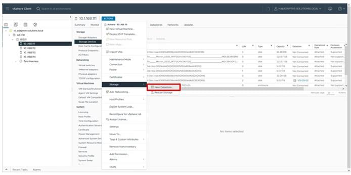
Step 6. Leave VMFS selected and click NEXT.
Step 7. Provide a name for the new datastore and select the LUN to use and click NEXT.
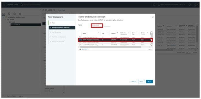
Step 8. Leave VMFS 6 selected and click NEXT.
Step 9. Leave the Partition configuration with the default values and click NEXT.
Step 10. Review the summary from Ready to complete and click FINISH.
Step 11. Repeat steps 5-10 for any additional LUNs provisioned.
Hitachi Storage Provider for VMware vCenter Initial Configuration
To prepare the VSP storage system for vVols, the storage administrator must configure a custom resource group. Within the resource group, admins must map the appropriate LDEVs that support the vVol pool, as well as a range of LDEVs IDs which are reserved for vVols creation. Additionally, you must map a single protocol endpoint (PE) to each ESXi server within the cluster.
Procedure 1. Access Hitachi Storage Navigator
You can access the storage system using the Hitachi Storage Navigator web user interface, which runs on the SVP. To connect to the SVP, ensure that Adobe AIR from HARMAN needs to be installed and configured on your machine, For more information, see the section Installing Storage Device Launcher on the management client here: https://knowledge.hitachivantara.com/Documents/Storage/VSP_5000_Series/90-07-0x/System_Configuration/01_Accessing_the_storage_system
After Adobe AIR from HARMAN is installed, you can proceed with the following steps to access Hitachi Storage Navigator.
Note: VSP E1090 will require an SVP to access Storage Navigator.
Step 1. Using a web browser, navigate to https://[SVP-IP-ADDRESS]/sanproject/emergency.do.
Step 2. Use the following credentials for the first-time login.
a. Username: maintenance
b. Password: raid-maintenance

Procedure 2. Create vVols user from Hitachi Storage Navigator
Step 1. From the Hitachi Storage Navigator web user interface, select Administration.
Step 2. Expand Administrator User Group under the Users tab, and then click Create User under the Users tab.
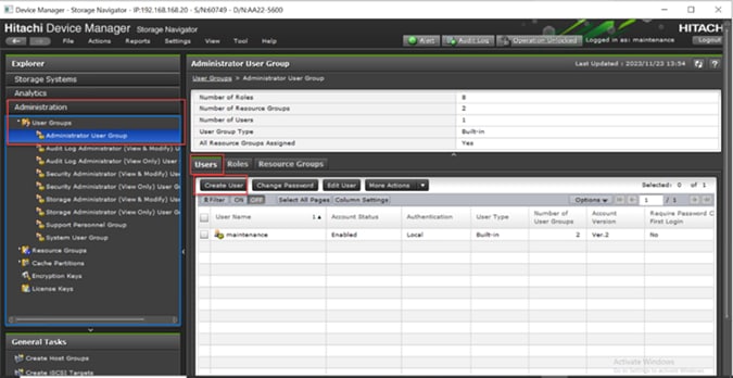
Step 3. Provide the following information:
a. Enter the Username.
b. Select the Enable option to activate the Account Status.
c. Select Authentication as the Local option.
d. Enter the Password and Re-enter Password.
Step 4. Click Finish.
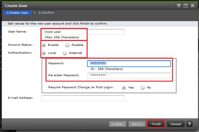
Step 5. Click Apply to create the Administrator User Account.
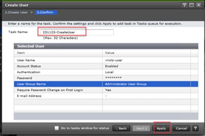
Note: If multiple Storage Providers for VMware vCenters are connecting to the storage, create a separate user account for each instance.
Procedure 3. Configure a Protocol Endpoint (PE) from Hitachi Device Manager - Storage Navigator
Step 1. Log in to Hitachi Storage Navigator.
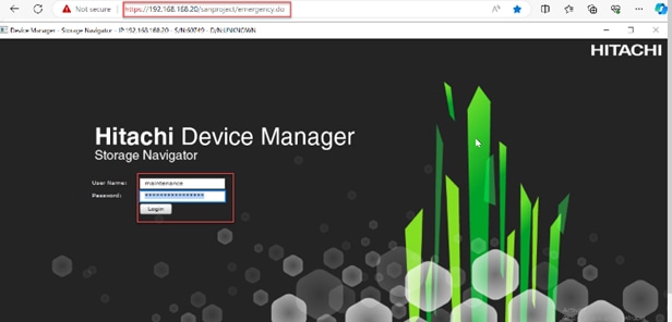
Step 2. From the Navigation pane, select the General Tasks panel. Click Create LDEVs.
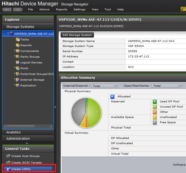
Step 3. Provide the following details:
a. Select ALU from the Provisioning Type drop-down list.
b. Enter the value 1 in the Number of LDEVs field.
Note: You only need one ALU.
c. Enter the LDEV name in the LDEV Name Prefix field.
d. Click Add.
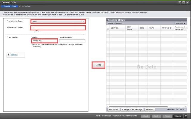
Step 4. The Selected LDEVs pane shows the PE created. Click Next to continue.

Step 5. Select the checkboxes for the available VSI Host Groups created from the Ops Center Administrator for the cluster.
Step 6. Click Add to move host groups to Selected Host Groups.
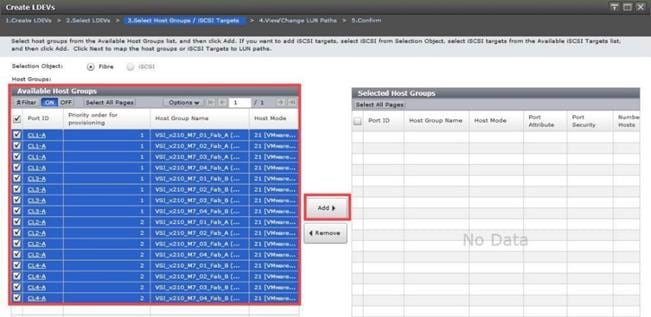
Step 7. Click Next.
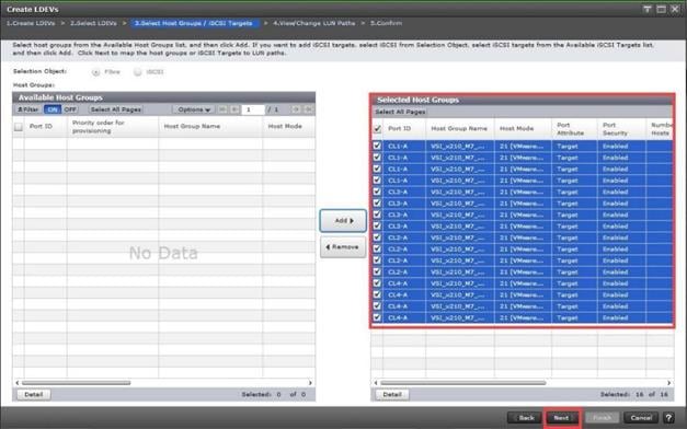
Step 8. (Optional) Ensure you use the scrollbar at the bottom of the dialog to double-check that all Host LUN IDs are set consistently across all paths. To do this, select the checkbox for all ports/paths listed, select the checkbox for the LDEV ID, and then click Change LUN IDs to make changes.
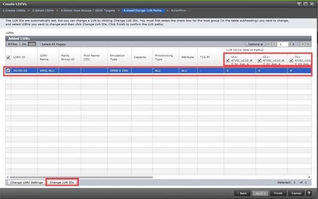
Step 9. Click OK.
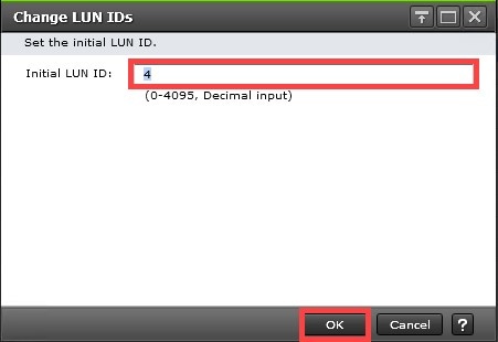
Step 10. Click Finish.
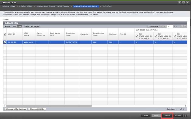
Step 11. Click Apply to create the LDEV and add paths to the UCS servers.
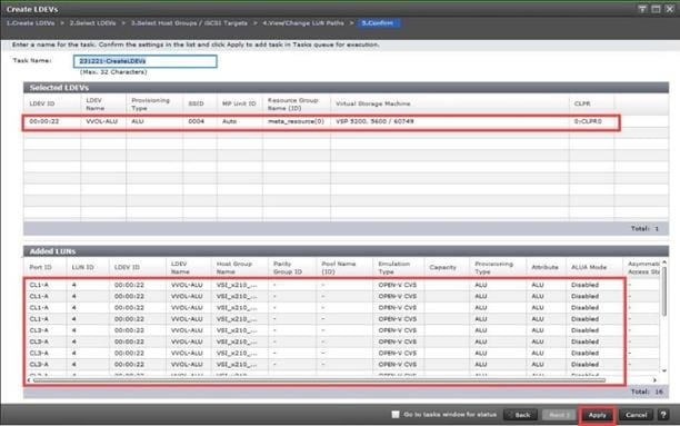
Procedure 4. Verify that the PE is Available and Visible
Verify that the protocol endpoint (PE) is visible in vSphere. On the storage system, the PE is the administrative logical unit (ALU) that the storage administrator presented to vSphere Cluster/ESXi hosts in the prior procedure.
Step 1. Log in to the vSphere Client, select Inventory from Home tab, and then select an ESXi host.
Step 2. Select Protocol Endpoints under the Configure tab.
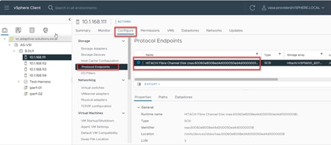
Step 3. (Optional), Using the ESXi host root console, you can view the protocol endpoints (PEs) by running the following command from the esxcli command line.
#esxcli storage core device list –p
This will display the devices that are recognized as PEs. Note the Is VVOL PE=True value.
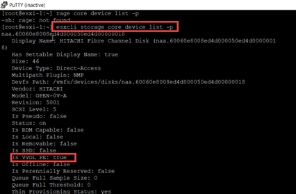
Procedure 5. Initialize Parity Groups with Hitachi Ops Center Administrator
Configuration steps in this section assume that Parity Groups have already been created by Hitachi professional services or using Hitachi Storage Navigator. For initializing Parity Groups from Hitachi Ops Center Administrator, proceed with the following steps:
Step 1. Log in to Hitachi Ops Center Administrator and select Storage Systems from the navigation pane.

Step 2. Select the S/N of the Virtual Storage Platform from the Storage Systems list.
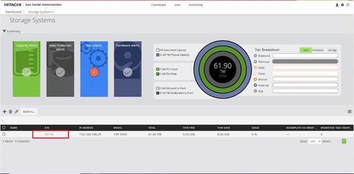
Step 3. Click the PARITY GROUPS icon under the selected storage system to view parity groups.

Step 4. Click any Parity Group ID to initialize it as parity for creating the vVol volume pool. From the Actions pane click Initialize Parity Groups.
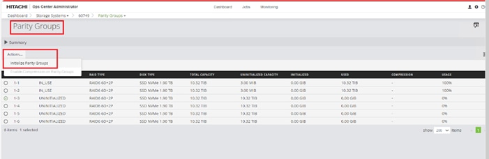
Step 5. Click OK.

Note: Created Parity Groups have status as UNINITIALIZED and after it gets initialized completely, the status should change to IN_USE.
Procedure 6. Create a Dynamic Provisioning Pool for vVols
When creating a pool, use the Basic option to take advantage of tiers of storage available on the VSP that are based on best practices. By default, the basic option will create a Hitachi Dynamic Provisioning Pool.
If you want more flexibility and do not need to take advantage of best practices, you can use the advanced option to select specific Parity Groups and define your pool types as either Tiered, Thin, or Snap.
Step 1. On the Ops Center Administrator dashboard, click Storage Systems to see the inventory of registered storage systems.

Step 2. Click the S/N listing of the Storage System.
Step 3. From the storage system, click Pools.
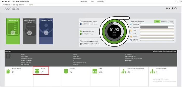
Step 4. Click the plus sign (+) to open the Create Storage Pool window.

Step 5. Enter the following details and click Submit.
a. Enter POOL NAME as vVOL_Dynamic_Pool (Pool names can contain alphanumeric characters, hyphens, and underscores only. Initial hyphens are not allowed.)
b. Click an available Tier to view the available storage capacity and select the available capacity.
c. Review the high and low pool utilization thresholds. By default, the utilization threshold low is set to 70% and high respectively at 80%. If required, you can modify thresholds to receive notifications for the thresholds that meet your environment needs.
d. To specify over allocation, you can set the limit to Unlimited.
e. Click Submit.
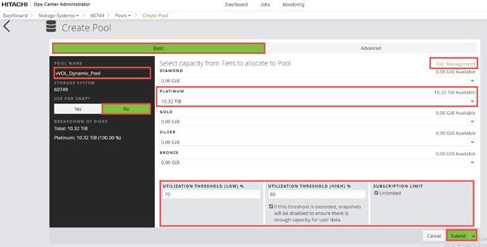
Procedure 7. Create vVols Resource Group from Hitachi Storage Navigator
Step 1. Log in to Hitachi Device Manager- Storage Navigator.

Step 2. Expand Administration, select Resource Groups, and click Create Resource Groups.
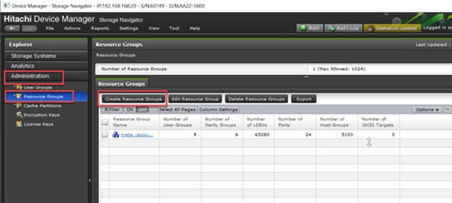
Step 3. Enter the Resource Group Name and click Select LDEVs.
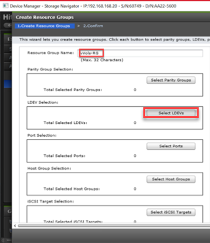
Step 4. Select an available range of LDEV IDs for reservation from the Available LDEVs tab, including the LDEVs created in the prior vVol pool step. Click Add.
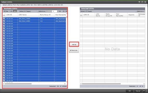
Step 5. Click OK to reserve the selected LDEVs to the Resource Group.
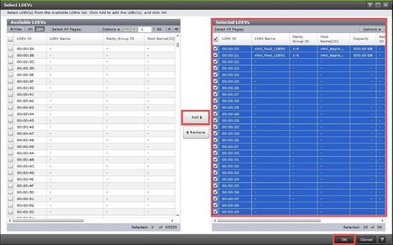
Step 6. After the LDEVs selection is completed, click Add.
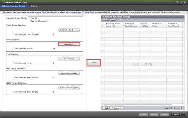
Step 7. The created Resource Group is visible under the Selected Resource Groups pane, and the Number of LDEVs are presented as selected. Click Finish.
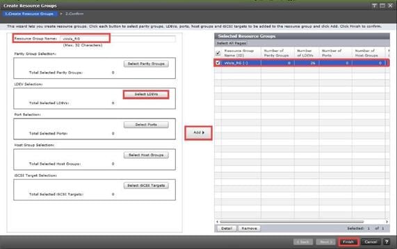
Step 8. Click Apply.
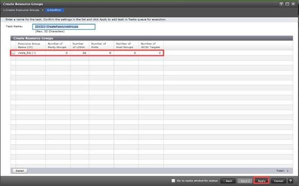
Procedure 8. Deploy Storage Provider for VMware vCenter
Storage Provider for VMware vCenter is deployed using an OVF template. You can obtain the binaries from your Hitachi representative or download the latest OVF file from - Support | Hitachi Vantara.
This virtual machine is typically deployed into the vSphere management cluster where the vCenter Appliance (VCSA) is deployed. You can also deploy this virtual machine to any vSphere environment if it has network access to the VSP storage.
Step 1. Log in to VMware vSphere web client.
Step 2. From the vCenter Dashboard, right-click Management Cluster and select Deploy OVF Template.
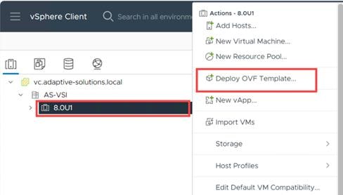
Step 3. Select the Local File, click UPLOAD FILES, and then select the respective OVA. Click Next.
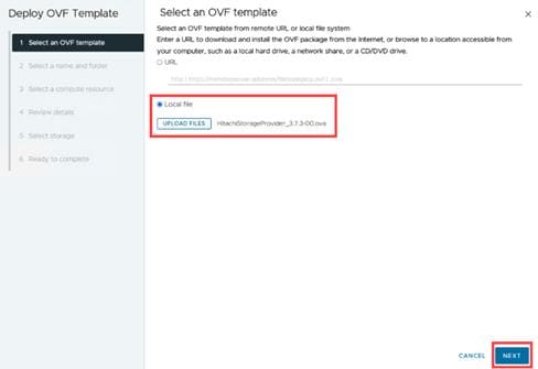
Step 4. Provide the name of the virtual machine and select the management cluster. Click NEXT.
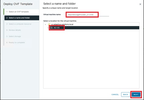
Step 5. Select the Compute Resource and click Next.
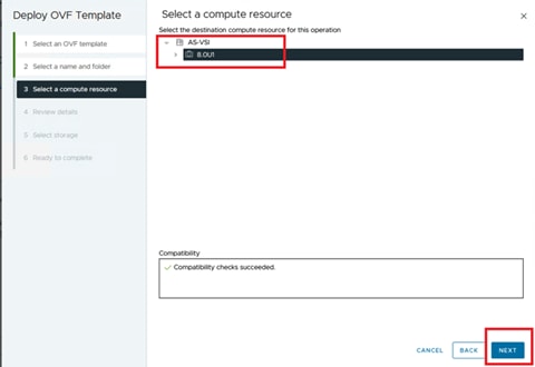
Step 6. Verify the template details and click Next.
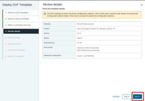
Step 7. Select the compatible Datastore and click Next.
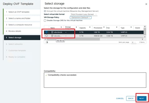
Step 8. Select the In-band Management Network and click Next.
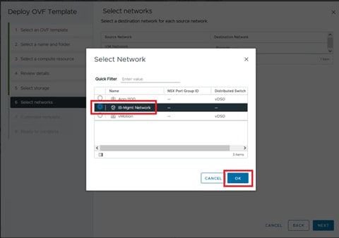
Step 9. Provide the following details:
● Network Configuration
◦ IP Address
◦ FQDN
◦ DNS
◦ Gateway
◦ Netmask
● SSO Server Configuration
◦ FQDN or IP Address: Enter the FQDN or IP address for the vCenter Single Sign-On Server.
◦ HTTPS Port: Enter the HTTPS Port Number 443 for vCenter SSO Server.
◦ Single Sign-On domain name: Enter the domain name for the vCenter SSO Server as vSphere.local
● System Configuration
◦ Domain Name
◦ Host Name
◦ NTP
Step 10. Click Next.
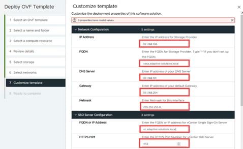
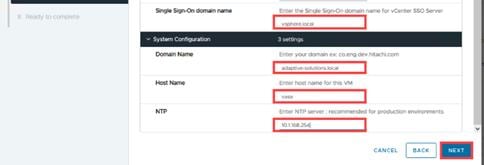
Step 11. Validate the details and click Finish.
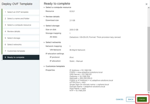
Step 12. Once the Storage Provider OVA has been deployed, Power On the virtual machine.
Step 13. In the browser, enter the IP Address or FQDN of Storage Provider for VMware vCenter with the following port number 50001. https://[Storage-Provider-IP-Address or FQDN]:50001/
Step 14. Enter the administrator SSO credentials for logging in to the VMware vCenter. Click Login.

Procedure 9. Onboard Hitachi VSP to Storage Provider for VMware vCenter
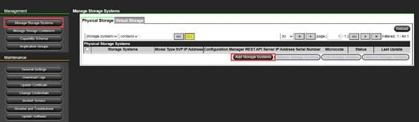
Step 2. Select a Storage System Type and enter the SVP IP address. Enter the vVols User ID and Password that you created earlier. Click OK.
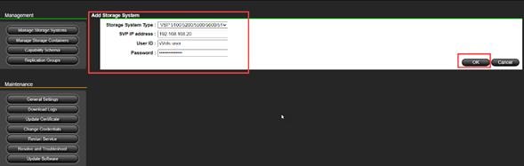
Note: Click Reload to update the progress until the storage system is added successfully.
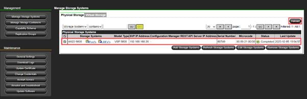
Procedure 10. Register Storage Provider for VMware vCenter in VMware vSphere
Step 1. Log in to the vSphere Client.
Step 2. Select vCenter. Click the Configure tab and select Storage Providers, and then click ADD.
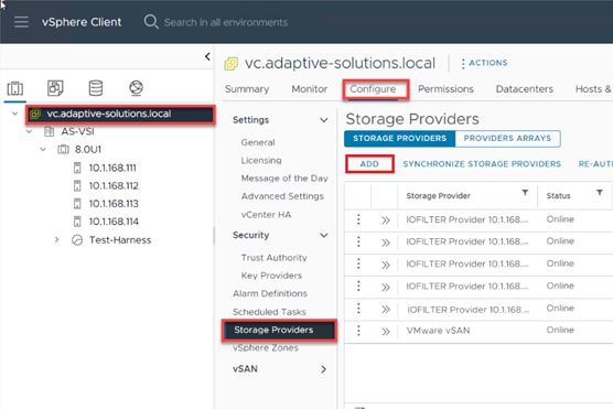
Step 3. Enter the following information:
a. Enter the Name for the New Storage Provider.
b. In the URL field, enter https://[Storage-Provider-FQDN]:50001/version.xml
c. In the Username field, enter the vCenter username in the format shown in the following figure.
d. In the Password field, enter the vCenter password.
e. Click OK.
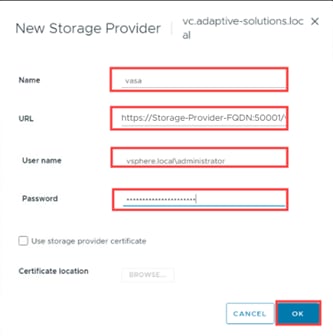
Step 4. In the Security Alert prompt, click YES.
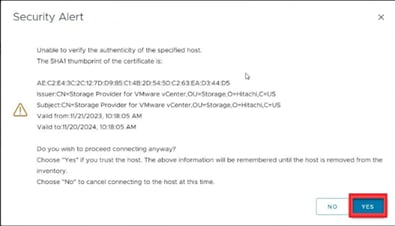
Step 5. After successful onboarding, the Storage Provider for VMware vCenter displays an Online status.
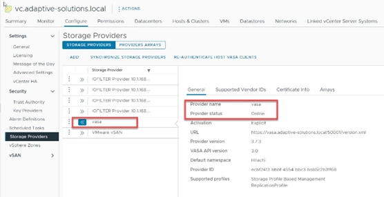
Procedure 11. Create a Storage Container for vVols and Define a Capability Profile from Storage Provider for VMware vCenter
Step 1. Log in to Storage Provider for VMware vCenter, from the Management pane select Manage Storage Containers, and then click Create Storage Container.
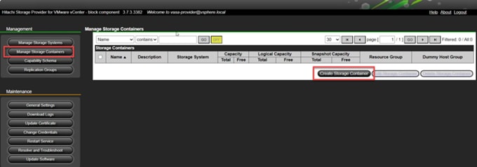
Step 2. Enter the following details:
a. Provide a Name for vVols Storage Container.
b. Select a Storage System.
c. Select the vVols Resource Group.
Step 3. Select the undefined Capability Profiles and click Define Profile.
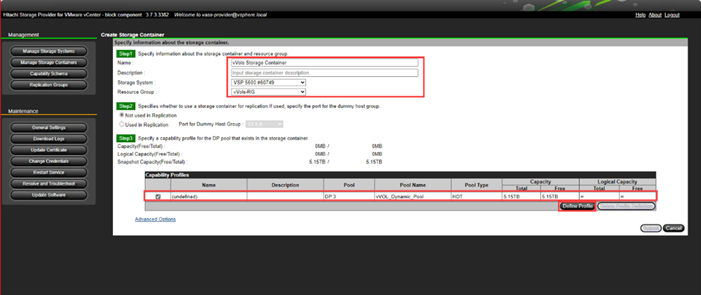
Step 4. Select the parameters for Managed Capabilities based on your environment and click OK. In the context of this guide, the following capabilities were selected.
a. Performance IOPS - class - Tier1_IOPS
b. Performance Latency - class - Tier1_Latency
c. Availability - class - Tier1
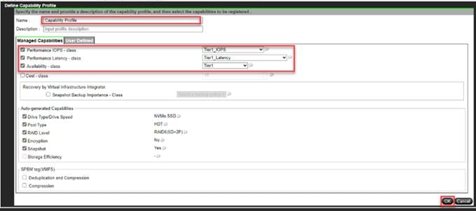
Step 5. Click Submit.
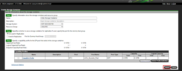
Procedure 1. Deploy vVols Datastore
Step 1. Log in to VMware vSphere client.
Step 2. Right-click the Cluster, select Storage, and then click New Datastore.
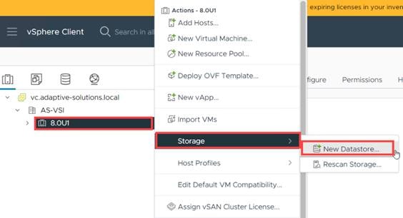
Step 3. In the New Datastore window, select vVol and click Next.
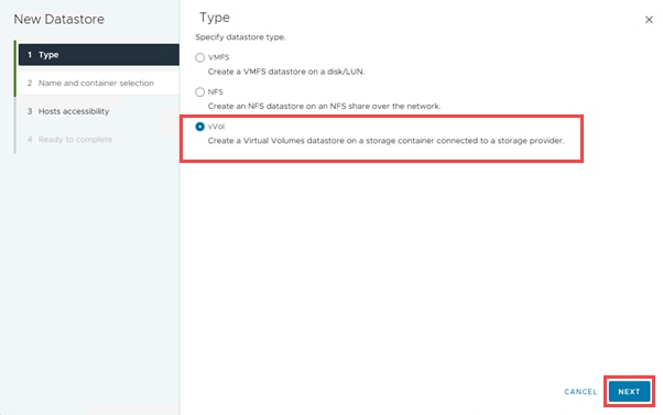
Step 4. Enter the Name for the datastore and select the Storage Container. Click Next.
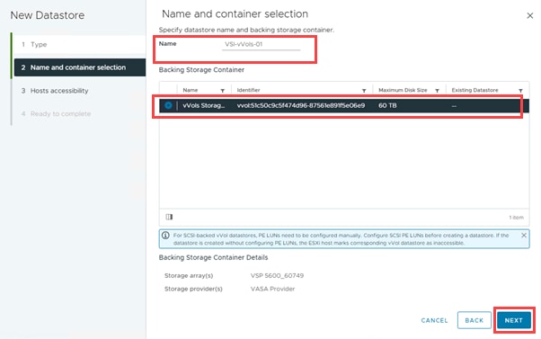
Step 5. Select all the Hosts that will be included in the vVols Datastore. Click Next.
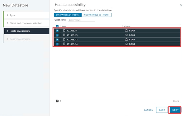
Step 6. Click Finish to create a vVols Datastore.
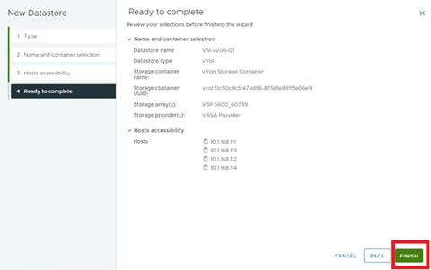
Procedure 2. Define a Virtual Machine Storage Profile
Step 1. Log in to VMware vSphere Client.

Step 2. Navigate to Policies and Profiles under vSphere Client Home tab.
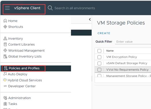
Step 3. Select the VM storage Policies and click Create.
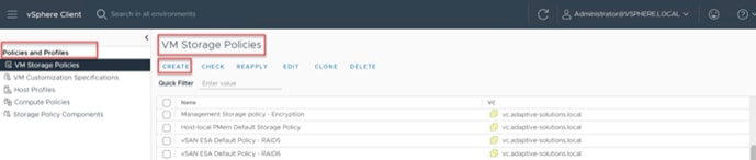
Step 4. Enter the Name and click Next.
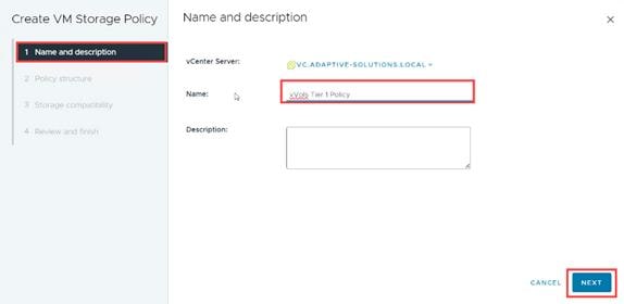
Step 5. Select the Datastore specific rules for Hitachi Storage provider and click Next.
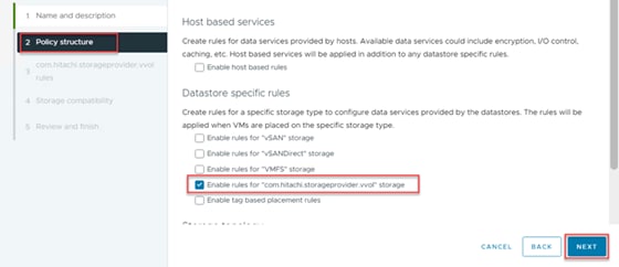
Step 6. Click ADD RULE for com.hitachi.storageprovider.vvol.
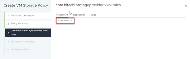
Step 7. Add the capabilities profiles as shown below:
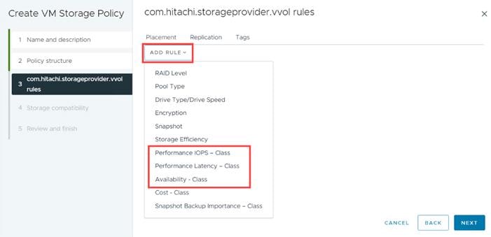
Step 8. Select the capabilities based on environment requirements. In the context of this document Tier1_IOPS, Tier1_Latency, and Tier1 Availability are selected. Click Next.
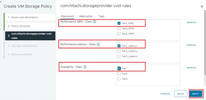
Step 9. Select the compatible datastore. Click Next.
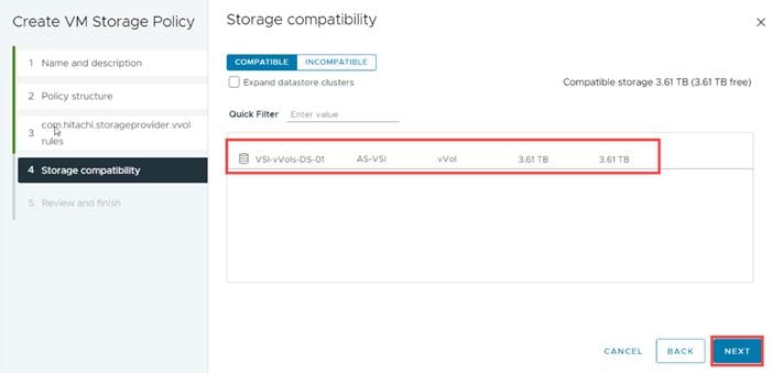
Step 10. Click Finish.
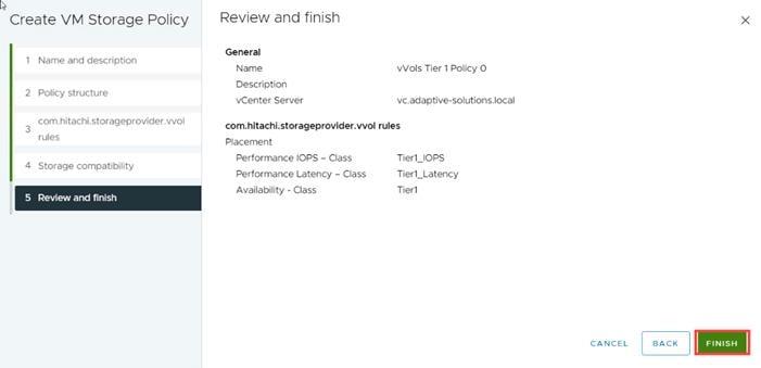
Storage Policy Based Management (SPBM) for VMFS LDEVs
Procedure 1. Storage Policy Based Management (SPBM) for VMFS LDEVs from Storage Provider for VMware vCenter
SPBM provides capabilities of applicable storage resources to VMware vCenter.
From the Hitachi Storage Provider for VMware vCenter, you define an LDEV profile to pass storage characteristics to VMware vCenter, such as IOPS, Latency, Availability, Drive RPM, and even storage location. To create an LDEV profile from Hitachi Storage Provider, follow these steps:
Step 1. Log in to Hitachi Storage Provider.
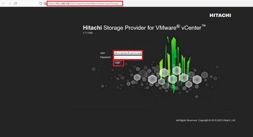
Step 2. Select Manage Storage Systems. Click LDEVs.
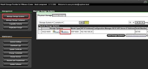
Step 3. Select the VMFS LDEV to provide capabilities for and click Define Profile.
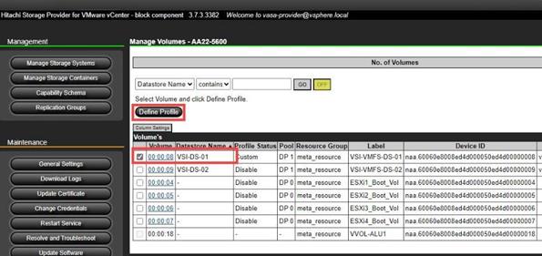
Step 4. Select the parameters for Managed Capabilities based on your environment and click OK. In the context of this guide the following capabilities were selected.
a. Performance IOPS - Class – Tier2_IOPS
b. Performance Latency - Class – Tier2_Latency
c. Availability - Class – Tier2
Step 5. Click Submit.
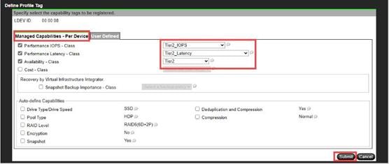
Procedure 2. Show VMFS Datastore with SPBM tags
Step 1. Log in to VMware vSphere Client.

Step 2. From vCenter, navigate to Inventory.
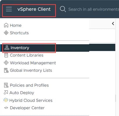
Step 3. Navigate to the Datastore section and select the VMFS Datastore.
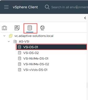
Step 4. After you have selected the Datastore, click Summary and view Storage Capabilities in the Tags pane.
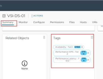
Host Image and vSphere Configuration Profiles
Procedure 1. Image Remediation
Step 1. From the Cluster view, select Updates > Hosts > Image, and select the first added host, and from ACTIONS, select Run pre-check.
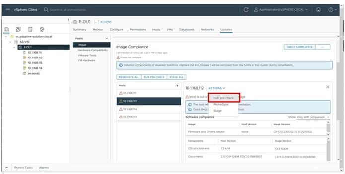
Step 2. With the pre-check run, re-select the added host and select Remediate from the ACTIONS menu.
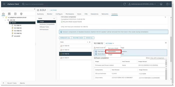
Step 3. Within the pop-up, click START REMEDIATION.
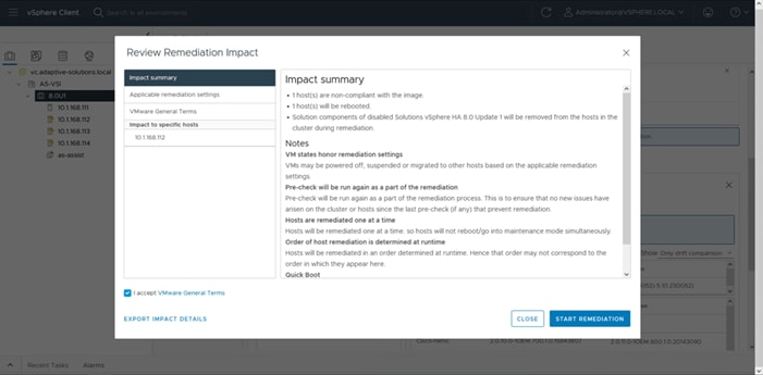
Step 4. Repeat steps 1 – 3 for each of the remaining hosts.
Procedure 2. Create Reference Configuration
Step 1. From the VSI cluster, click Configure > Desired State > Configuration.
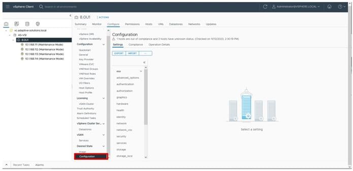
Step 2. Click the … box and select Extract from reference host.
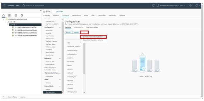
Step 3. Select the first ESXi host that has been manually configured and click NEXT.
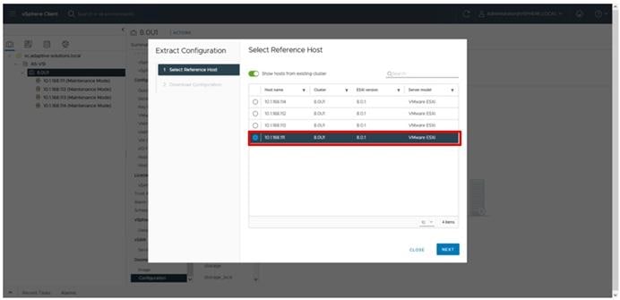
Step 4. Click DOWNLOAD.
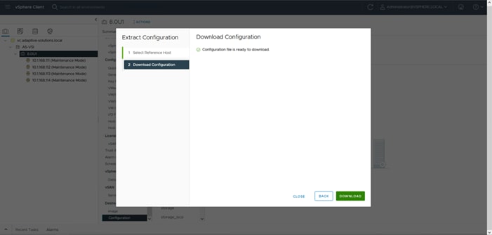
Procedure 3. Add Additional Hosts
Step 1. Open the downloaded JSON file in an editor. Notepad++ is used in our example.
Step 2. Find the host-specific section within the JSON file, highlight the UUID bracket section and copy it.
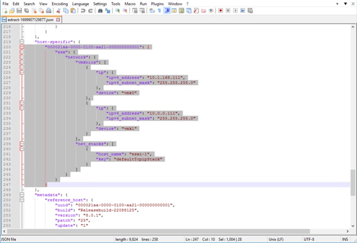
Step 3. Create additional tabs or files for each host to be configured and copy the host-specific JSON text.
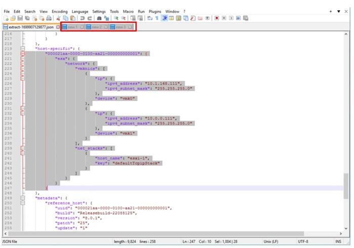
Step 4. Paste this copied host-specific JSON section into each tab.
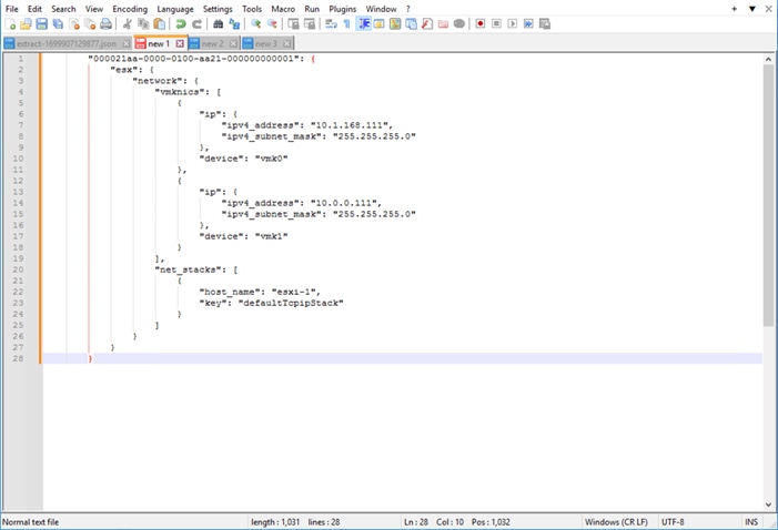
Step 5. Adjust the UUID (top alpha-numeric sequence above the “esx”: line) with the UUID values for each additional host, along with adjustments for their respective VMkernel IPs and host names.
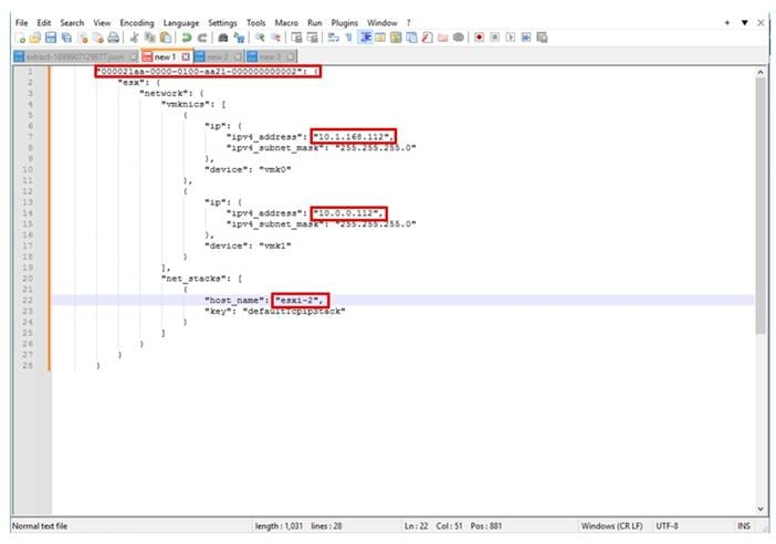
Step 6. Add a comma after the first UUID block in the original JSON file.
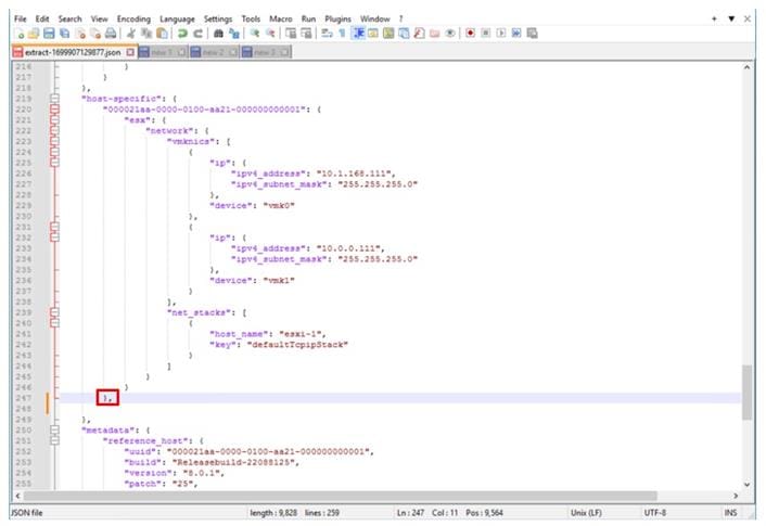
Step 7. Insert each additional host UUID block segments into the file after the comma, with commas separating each additional host, and then save the file.
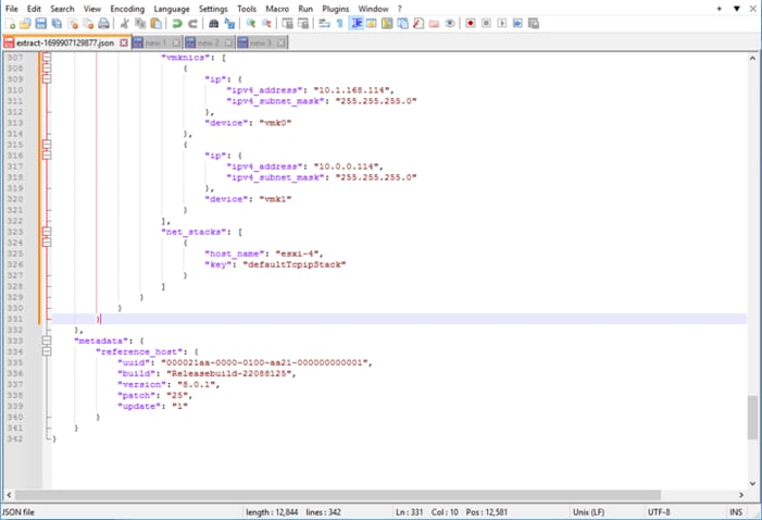
Note: The last host block inserted will not have a comma added to it.
Step 8. From vCenter, return to the cluster Configure > Configuration, and click IMPORT.
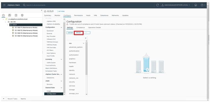
Step 9. Browse for the adjusted JSON file and click IMPORT.
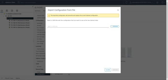
Step 10. Click CLOSE after the import completes.
Procedure 4. Remediate Hosts
Step 1. Click the Compliance tab of Configure > Desired State > Configuration of the VSI cluster, select a non-compliant host, and click RUN PRE-CHECK.
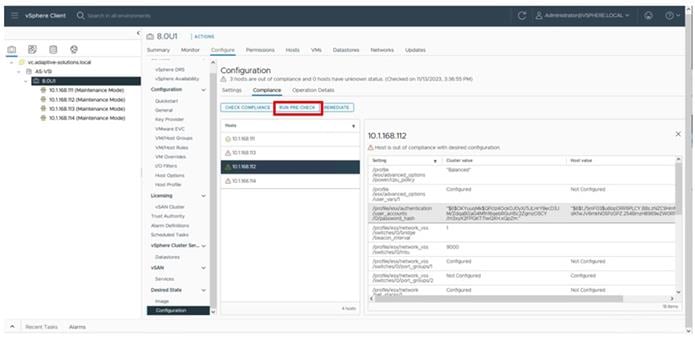
Step 2. With the pre-check completed, click REMEDIATE.
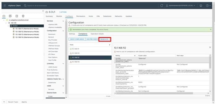
Step 3. Click NEXT after the PRE-CHECK and then click REMEDIATE on the Review Impact screen.
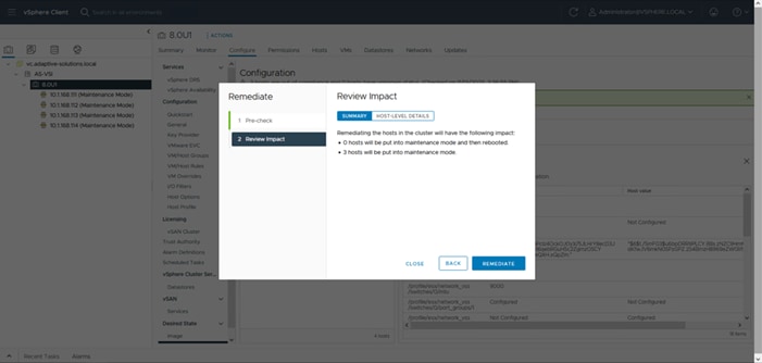
Step 4. With remediation complete, remove all hosts from Maintenance Mode.
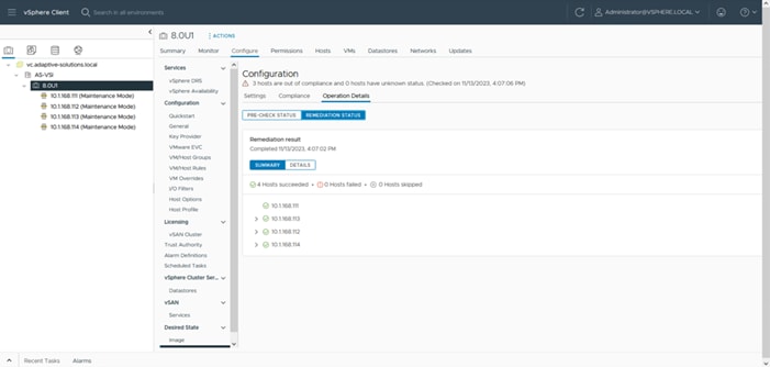
vSphere Additional Finishing Steps
Procedure 5. VMware ESXi 8.0 U1 TPM Attestation
Note: If your Cisco UCS servers have Trusted Platform Module (TPM) 2.0 modules installed, the TPM can provide assurance that ESXi has booted with UEFI Secure Boot enabled and using only digitally signed code. In the Cisco UCS Configuration section of this document, UEFI secure boot was enabled in the boot order policy. A server can boot with UEFI Secure Boot with or without a TPM 2.0 module. If it has a TPM, VMware vCenter can attest that the server booted with UEFI Secure Boot. To verify the VMware ESXi 8.0 U1 TPM Attestation, follow these steps:
Step 1. For Cisco UCS servers that have TPM 2.0 modules installed, TPM Attestation can be verified within vCenter.
Step 2. In the vCenter under Hosts and Clusters select the cluster.
Step 3. In the center pane, choose the Monitor tab.
Step 4. Click Monitor > Security. The Attestation status will show the status of the TPM:
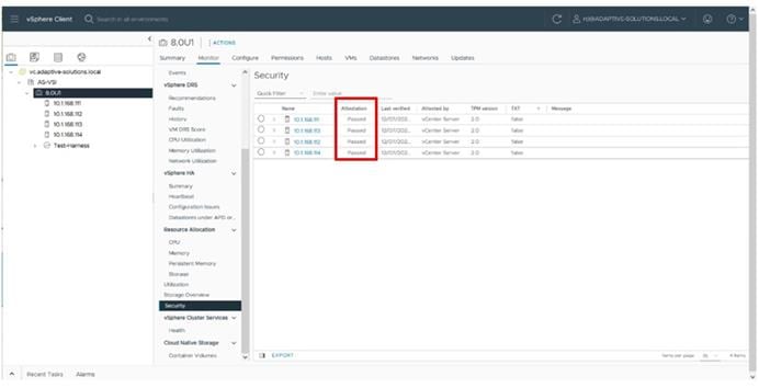
Note: It may be necessary to disconnect and reconnect or reboot a host from vCenter to get it to pass attestation the first time.
Procedure 6. (Optional) Configure Distributed Power Management (DPM)
This procedure configures the host to be able to be shut down during low cluster utilization times to reduce power.
The CIMC Management interface associated with the DPM BMC MAC address will need to be gathered from the Fabric Interconnect Device Console CLI, either from direct console connection, or via ssh.
To gather the CIMC Management interface MAC addresses, perform the following steps:
Step 1. Connect to either Fabric Interconnect Device Console as admin.
% ssh admin@192.168.168.11
Cisco UCS 6500 Series Fabric Interconnect
admin@192.168.168.12's password:
UCS Intersight Management
AA21-6536-A#
Step 2. Connect to the CIMC Debug Firmware Utility Shell of the first server (connect cimc <chassis>/<blade slot>) from which to collect information.
AA21-6536-B# connect cimc 1/1
Entering character mode
Escape character is '^]'.
CIMC Debug Firmware Utility Shell [ ]
[ help ]#
Step 3. Run the network command and identify the first server MAC (HWaddr) address for the eth0 value from the top of the output that returns.
[ help ]# network
eth0 Link encap:Ethernet HWaddr 56:51:DE:D5:87:E9
inet6 addr: fe80::5451:deff:fed5:87e9/64 Scope:Link
UP BROADCAST RUNNING MULTICAST MTU:1500 Metric:1
RX packets:48387344 errors:0 dropped:0 overruns:0 frame:0
TX packets:37023312 errors:0 dropped:0 overruns:0 carrier:0
collisions:0 txqueuelen:1000
RX bytes:18446744071908661842 (16777215.9 TiB) TX bytes:1097208517 (1.0 GiB)
Interrupt:50
Step 4. Type exit and repeat steps 2 and 3 for each server.
Note: With the information gathered for each server to configure, continue with the following steps:
Step 5. From the first host that has been added, go to Configure > System > Power Management and click EDIT… .
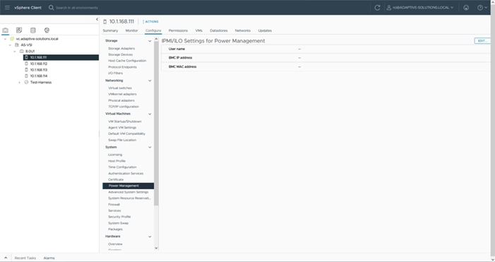
Step 6. Provide the credentials for a local user with admin privileges within the UCS domain, the assigned KVM mgmt IP from Intersight, and the CIMC MAC address previously collected from the Fabric Interconnect Device Console.
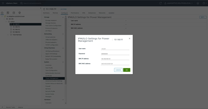
Step 7. Repeat Step 2 for each additional host in the cluster.
Note: The MAC addresses used in this configuration are associated with the physical hardware of the server and will need to be re-entered if the server profiles associated with these hosts are deployed to different servers.
Step 8. Go to Configure > Services > vSphere DRS for the cluster and click EDIT….
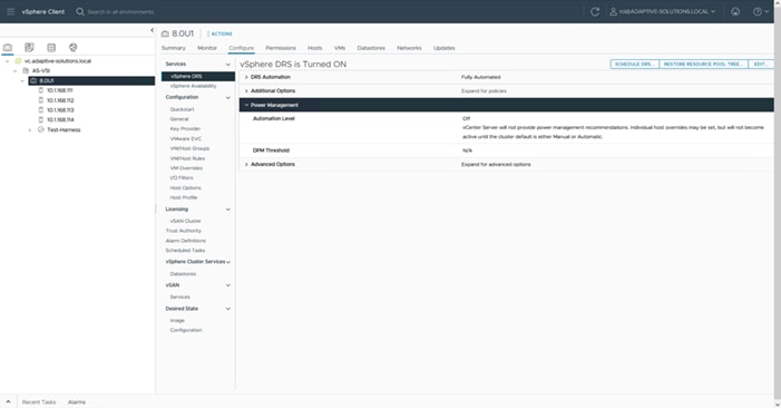
Step 9. Select the Power Management tab within the Edit Cluster Settings window, click the Enable checkbox for DPM, and select the Automatic option from the Automation Level drop-down list.
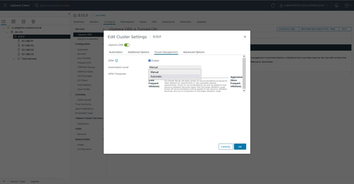
Step 10. Click OK to apply the changes.
Step 11. Click OK past any warnings about the standby functionality of certain hosts, or alternately test each host for standby now that it has been configured and repeat Step 5.
Ramesh Isaac, Technical Marketing Engineer, Cisco Systems, Inc.
Ramesh Isaac is a Technical Marketing Engineer in the Cisco UCS Data Center Solutions Group. Ramesh has worked in the data center and mixed-use lab settings for over 25 years. He started in information technology supporting UNIX environments and focused on designing and implementing multi-tenant virtualization solutions in Cisco labs before entering Technical Marketing where he has supported converged infrastructure and virtual services as part of solution offerings as Cisco. Ramesh has held certifications from Cisco, VMware, and Red Hat.
Ramakrishna Manupuri, Senior Software Development Engineer, Hitachi Vantara
Ramakrishna Manupuri is a Senior Software Development Engineer, in the Solutions Engineering team of Converged UCP group. He has worked as a Solution engineer with mainly experience in UCP products, Cloud services, SAN Storage solutions and Virtualization technologies with expertise in VMware products such as VMware Cloud Foundation (Hyperconverged infrastructure solution), vCloud Director, vSphere, vSAN, VMware Site Recovery Manager (SRM). Ramakrishna has held certifications from VMware (VCP), AWS Solutions Architect - Associate and Fortinet (NSE4).
Sandeep Rakshe, Senior Software Development Engineer, Hitachi Vantara
Sandeep Rakshe is a Senior Software Development Engineer in the Hitachi Engineering Converged UCP group. Sandeep has worked as QA and Solutions group with mainly experience in disaster recovery solutions. He started in information technology with different FC and NAS Storages with expertise in products such as Symantec NetBackup, Veritas Storage foundation, Hitachi Ops Center Protector and Unified compute advisor (Hyperconverged infrastructure solutions), IBM IP flash system IP replication, VMware vSAN. Sandeep has held certifications from Cisco and Red Hat
Acknowledgements
For their support and contribution to the design, validation, and creation of this Cisco Validated Design, the authors would like to thank:
● John George, Technical Marketing Engineer, Cisco Systems, Inc.
● Archana Sharma, Engineering Technical Leader, Cisco Systems, Inc.
● Arvin Jami, Solutions Architect, Hitachi Vantara
This appendix contains the following:
● Allocate a VMFS Datastore with Cisco Intersight Cloud Orchestrator using Hitachi VSP
● MDS Configurations used in this validation
● Nexus Configurations used in this validation
Allocate a VMFS Datastore with Cisco Intersight Cloud Orchestrator using Hitachi VSP
Intersight Cloud Orchestrator (ICO) enables administrators to allocate a VMFS datastore from system-defined workflow New VMFS Datastore, this single workflow is a combination of tasks that carves the virtual volume from an existing pool, adds LUN paths to a single host in a cluster with an associated LUN ID, and then onboards the datastore within VMware vCenter to the selected host. After the initial datastore has been mounted, administrators can use the ICO workflow output logs to identify the volume backing the datastore, after identified administrators must use ICO task New Storage LUN ID to allocate to other hosts within the desired cluster and any other multipaths required. A storage rescan from the ESXi host will be required.
Procedure 1. Use the New VMFS Datastore from the system-defined workflow
Step 1. Select Cloud Orchestrator from the system drop-down list, click Workflows, and click Sample Workflows tab.
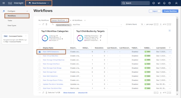
Step 2. From the predefined list, select New VMFS Datastore. Click Execute.
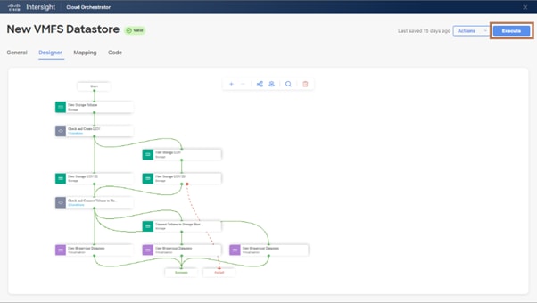
Step 3. From the Workflow Input wizard, select the Storage Device, LUN ID, Volume Label, Data Reduction Mode, Volume Size and Unit, Storage Host (Host Group), Port ID, Host Group Number, Hypervisor Manager, Data Center, Cluster, Host, Datastore Name, and Datastore Type. Click Execute.
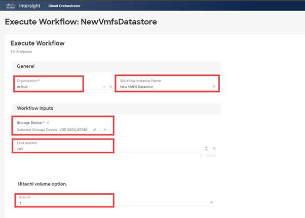
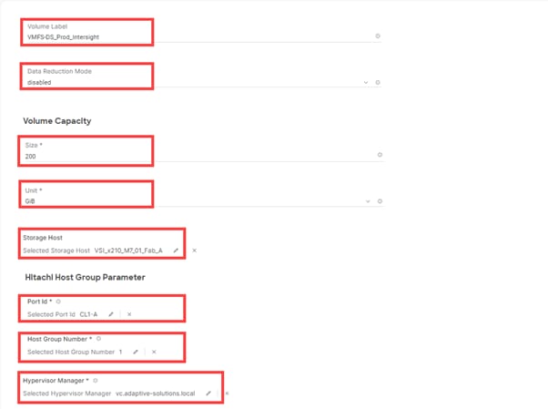
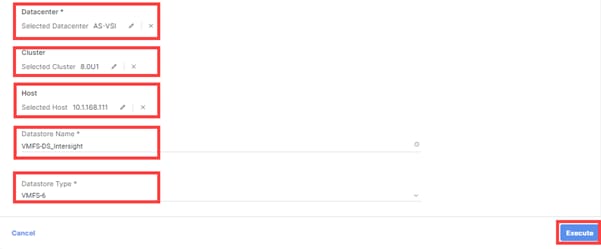
If input parameters are correct, ICO displays Success after the task is complete:
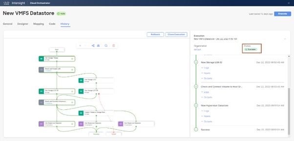
Step 4. After the task is complete, expand New Storage Volume Task > Outputs to view the created LDEV ID in decimal:
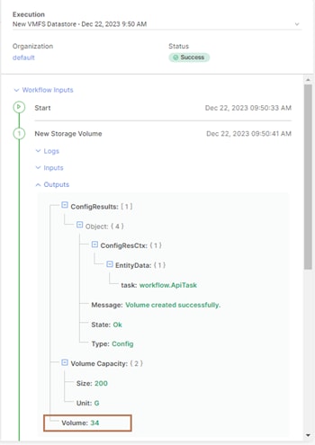
If multipathing or any other pathing to additional hosts is required, administrators are required to use New Storage LUN ID as explained in the VSP with Cisco Intersight Cloud Orchestrator best practices guide: https://www.hitachivantara.com/en-us/pdfd/architecture-guide/vsp-with-cisco-intersight-cloud-orchestrator.pdf to allocate the volume to other hosts. A manual HBA rescan from the host is required to discover VMFS datastore after allocation is complete.
MDS Configurations used in this validation
MDS A Configuration
version 9.3(2)
power redundancy-mode redundant
license smart transport smart
system default switchport mode F
feature fport-channel-trunk
feature nxapi
role name default-role
description This is a system defined role and applies to all users.
rule 5 permit show feature environment
rule 4 permit show feature hardware
rule 3 permit show feature module
rule 2 permit show feature snmp
rule 1 permit show feature system
username admin password 5 $5$Wor/sHUt$qlWc3XEUwEufzrMpHVwPdQdWeOgOmlBQ0aoP0sAPE61 role network-admin
username svc-nxcloud password 5 ! role network-admin
username svc-nxcloud passphrase lifetime 99999 warntime 14 gracetime 3
username snmpadmin password 5 $5$I87vpH8F$Nxo6Ss6qcqiq2Yt5nwjsdydxgV3KBdrKYI2et7wTro. role network-admin
username snmpadmin passphrase lifetime 99999 warntime 14 gracetime 3
ip domain-lookup
ip domain-name adaptive-solutions.local
ip name-server 192.168.160.53
ip host AA21-9124V-1 192.168.168.15
aaa group server radius radius
snmp-server contact vsiuser@adaptive-solutions.local
snmp-server user admin network-admin auth md5 0xe4c3b09168f2dc77ecb2ee99b1425233 priv aes-128 0xe4c3b09168
f2dc77ecb2ee99b1425233 localizedkey
snmp-server user snmpadmin network-admin auth sha 0x257e997f8e55f3c21deab856dc2bdc7bf6a7fa36 priv aes-128
0x257e997f8e55f3c21deab856dc2bdc7bf6a7fa36 localizedkey
snmp-server host 192.168.168.92 traps version 2c public udp-port 2162
snmp-server host 192.168.168.94 traps version 2c public udp-port 2162
rmon event 1 log trap public description FATAL(1) owner PMON@FATAL
rmon event 2 log trap public description CRITICAL(2) owner PMON@CRITICAL
rmon event 3 log trap public description ERROR(3) owner PMON@ERROR
rmon event 4 log trap public description WARNING(4) owner PMON@WARNING
rmon event 5 log trap public description INFORMATION(5) owner PMON@INFO
port-monitor name fabricmon_edge_policy
logical-type edge
counter link-loss poll-interval 30 delta rising-threshold 5 event 4 falling-threshold 1 event 4 alerts s
yslog rmon portguard FPIN
counter sync-loss poll-interval 30 delta rising-threshold 5 event 4 falling-threshold 1 event 4 alerts s
yslog rmon portguard FPIN
counter signal-loss poll-interval 30 delta rising-threshold 5 event 4 falling-threshold 1 event 4 alerts
syslog rmon portguard FPIN
counter invalid-words poll-interval 30 delta rising-threshold 1 event 4 falling-threshold 0 event 4 aler
ts syslog rmon portguard FPIN
counter invalid-crc poll-interval 30 delta rising-threshold 5 event 4 falling-threshold 1 event 4 alerts
syslog rmon portguard FPIN
counter state-change poll-interval 60 delta rising-threshold 5 event 4 falling-threshold 0 event 4 alert
s syslog rmon
counter tx-discards poll-interval 60 delta rising-threshold 200 event 4 falling-threshold 10 event 4 ale
rts syslog rmon
counter lr-rx poll-interval 60 delta rising-threshold 5 event 4 falling-threshold 1 event 4 alerts syslo
g rmon
counter lr-tx poll-interval 60 delta rising-threshold 5 event 4 falling-threshold 1 event 4 alerts syslo
g rmon
counter timeout-discards poll-interval 60 delta rising-threshold 200 event 4 falling-threshold 10 event
4 alerts syslog rmon
counter credit-loss-reco poll-interval 1 delta rising-threshold 1 event 4 falling-threshold 0 event 4 al
erts syslog rmon
counter tx-credit-not-available poll-interval 1 delta rising-threshold 10 event 4 falling-threshold 0 ev
ent 4 alerts syslog rmon
counter rx-datarate poll-interval 10 delta rising-threshold 80 event 4 falling-threshold 70 event 4 aler
ts syslog rmon obfl
counter tx-datarate poll-interval 10 delta rising-threshold 80 event 4 falling-threshold 70 event 4 aler
ts syslog rmon obfl
no monitor counter err-pkt-from-port
no monitor counter err-pkt-to-xbar
no monitor counter err-pkt-from-xbar
counter tx-slowport-oper-delay poll-interval 1 absolute rising-threshold 50 event 4 falling-threshold 0
event 4 alerts syslog rmon
counter txwait poll-interval 1 delta rising-threshold 30 event 4 falling-threshold 10 event 4 alerts sys
log rmon portguard FPIN
counter txwait warning-signal-threshold 40 alarm-signal-threshold 60 portguard congestion-signals
no monitor counter sfp-tx-power-low-warn
no monitor counter sfp-rx-power-low-warn
counter rx-datarate-burst poll-interval 10 delta rising-threshold 5 event 4 falling-threshold 1 event 4
alerts syslog rmon obfl datarate 90
counter tx-datarate-burst poll-interval 10 delta rising-threshold 5 event 4 falling-threshold 1 event 4
alerts syslog rmon obfl datarate 90
counter input-errors poll-interval 60 delta rising-threshold 5 event 4 falling-threshold 1 event 4 alert
s syslog rmon
callhome
email-contact rci@cisco.com
destination-profile xml transport-method http
destination-profile xml email-addr sl-sch-test@cisco.com
destination-profile xml email-addr rci@cisco.com
destination-profile xml http https://tools.cisco.com/its/service/oddce/services/DDCEService
enable
ntp server 192.168.168.254
vsan database
vsan 101 name "Fabric-A"
device-alias database
device-alias name AA21-esxi-1 pwwn 20:00:00:25:b5:21:0a:00
device-alias name AA21-esxi-2 pwwn 20:00:00:25:b5:21:0a:02
device-alias name AA21-esxi-3 pwwn 20:00:00:25:b5:21:0a:04
device-alias name AA21-esxi-4 pwwn 20:00:00:25:b5:21:0a:06
device-alias name AA21-esxi-5 pwwn 20:00:00:25:b5:21:0a:08
device-alias name AA21-esxi-6 pwwn 20:00:00:25:b5:21:0a:0a
device-alias name AA22-5600-0-1a pwwn 50:06:0e:80:08:ed:4d:00
device-alias name AA22-5600-1-2a pwwn 50:06:0e:80:08:ed:4d:10
device-alias name AA21-esxi-1-fc-nvme pwwn 20:00:00:25:b5:21:0a:01
device-alias name AA21-esxi-2-fc-nvme pwwn 20:00:00:25:b5:21:0a:03
device-alias name AA21-esxi-3-fc-nvme pwwn 20:00:00:25:b5:21:0a:05
device-alias name AA21-esxi-4-fc-nvme pwwn 20:00:00:25:b5:21:0a:07
device-alias name AA21-esxi-5-fc-nvme pwwn 20:00:00:25:b5:21:0a:09
device-alias name AA21-esxi-6-fc-nvme pwwn 20:00:00:25:b5:21:0a:0b
device-alias name AA22-5600-0-1b-fc-nvme pwwn 50:06:0e:80:08:ed:4d:01
device-alias name AA22-5600-1-2b-fc-nvme pwwn 50:06:0e:80:08:ed:4d:11
device-alias commit
fcdomain fcid database
vsan 1 wwn 50:06:0e:80:08:ed:4d:10 fcid 0x0e0000 dynamic
! [AA22-5600-1-2a]
vsan 1 wwn 50:06:0e:80:08:ed:4d:11 fcid 0x0e0020 dynamic
! [AA22-5600-1-2b-fc-nvme]
vsan 1 wwn 50:06:0e:80:08:ed:4d:00 fcid 0x0e0040 dynamic
! [AA22-5600-0-1a]
vsan 1 wwn 50:06:0e:80:08:ed:4d:01 fcid 0x0e0060 dynamic
! [AA22-5600-0-1b-fc-nvme]
vsan 101 wwn 50:06:0e:80:08:ed:4d:10 fcid 0xcc0000 dynamic
! [AA22-5600-1-2a]
vsan 101 wwn 50:06:0e:80:08:ed:4d:11 fcid 0xcc0020 dynamic
! [AA22-5600-1-2b-fc-nvme]
vsan 101 wwn 50:06:0e:80:08:ed:4d:00 fcid 0xcc0040 dynamic
! [AA22-5600-0-1a]
vsan 101 wwn 50:06:0e:80:08:ed:4d:01 fcid 0xcc0060 dynamic
! [AA22-5600-0-1b-fc-nvme]
vsan 101 wwn 24:01:00:08:31:33:76:7c fcid 0xcc0080 dynamic
vsan 101 wwn 20:00:00:25:b5:21:0a:00 fcid 0xcc0081 dynamic
! [AA21-esxi-1]
vsan 101 wwn 20:00:00:25:b5:21:0a:02 fcid 0xcc0082 dynamic
! [AA21-esxi-2]
vsan 101 wwn 20:00:00:25:b5:21:0a:04 fcid 0xcc0083 dynamic
! [AA21-esxi-3]
vsan 101 wwn 20:00:00:25:b5:21:0a:06 fcid 0xcc0084 dynamic
! [AA21-esxi-4]
vsan 101 wwn 24:65:00:08:31:33:76:7c fcid 0xcc0085 dynamic
vsan 101 wwn 20:00:00:25:b5:21:0a:01 fcid 0xcc0086 dynamic
! [AA21-esxi-1-fc-nvme]
vsan 101 wwn 20:00:00:25:b5:21:0a:03 fcid 0xcc0087 dynamic
! [AA21-esxi-2-fc-nvme]
vsan 101 wwn 20:00:00:25:b5:21:0a:05 fcid 0xcc0088 dynamic
! [AA21-esxi-3-fc-nvme]
vsan 101 wwn 20:00:00:25:b5:21:0a:07 fcid 0xcc0089 dynamic
! [AA21-esxi-4-fc-nvme]
vsan 101 wwn 20:00:00:25:b5:21:0a:0a fcid 0xcc008a dynamic
! [AA21-esxi-6]
vsan 101 wwn 20:00:00:25:b5:21:0a:08 fcid 0xcc008b dynamic
! [AA21-esxi-5]
vsan 101 wwn 20:00:00:25:b5:21:0a:09 fcid 0xcc008c dynamic
! [AA21-esxi-5-fc-nvme]
vsan 101 wwn 20:00:00:25:b5:21:0a:0b fcid 0xcc008d dynamic
! [AA21-esxi-6-fc-nvme]
system default zone distribute full
zone smart-zoning enable vsan 101
zoneset distribute full vsan 101
!Active Zone Database Section for vsan 101
zone name FC-AA22-5600 vsan 101
member device-alias AA21-esxi-1 init
member device-alias AA21-esxi-2 init
member device-alias AA21-esxi-3 init
member device-alias AA21-esxi-4 init
member device-alias AA22-5600-0-1a target
member device-alias AA22-5600-1-2a target
member device-alias AA21-esxi-5 init
member device-alias AA21-esxi-6 init
zone name FC-NVMe-AA22-5600 vsan 101
member device-alias AA21-esxi-1-fc-nvme init
member device-alias AA21-esxi-2-fc-nvme init
member device-alias AA21-esxi-3-fc-nvme init
member device-alias AA21-esxi-4-fc-nvme init
member device-alias AA22-5600-0-1b-fc-nvme target
member device-alias AA22-5600-1-2b-fc-nvme target
member device-alias AA21-esxi-5-fc-nvme init
member device-alias AA21-esxi-6-fc-nvme init
zoneset name Fabric-A vsan 101
member FC-AA22-5600
member FC-NVMe-AA22-5600
zoneset activate name Fabric-A vsan 101
do clear zone database vsan 101
!Full Zone Database Section for vsan 101
zone name FC-AA22-5600 vsan 101
member device-alias AA21-esxi-1 init
member device-alias AA21-esxi-2 init
member device-alias AA21-esxi-3 init
member device-alias AA21-esxi-4 init
member device-alias AA22-5600-0-1a target
member device-alias AA22-5600-1-2a target
member device-alias AA21-esxi-5 init
member device-alias AA21-esxi-6 init
zone name FC-NVMe-AA22-5600 vsan 101
member device-alias AA21-esxi-1-fc-nvme init
member device-alias AA21-esxi-2-fc-nvme init
member device-alias AA21-esxi-3-fc-nvme init
member device-alias AA21-esxi-4-fc-nvme init
member device-alias AA22-5600-0-1b-fc-nvme target
member device-alias AA22-5600-1-2b-fc-nvme target
member device-alias AA21-esxi-5-fc-nvme init
member device-alias AA21-esxi-6-fc-nvme init
zoneset name Fabric-A vsan 101
member FC-AA22-5600
member FC-NVMe-AA22-5600
interface mgmt0
ip address 192.168.168.15 255.255.255.0
interface port-channel101
switchport trunk allowed vsan 101
switchport description AA21-6536-A
switchport speed 32000
switchport rate-mode dedicated
vsan database
vsan 101 interface port-channel101
vsan 101 interface fc1/5
vsan 101 interface fc1/6
vsan 101 interface fc1/7
vsan 101 interface fc1/8
clock timezone EST -5 0
clock summer-time EDT 2 Sunday March 02:00 1 Sunday November 02:00 60
switchname AA21-9124V-1
no terminal log-all
line console
line vty
boot kickstart bootflash:/m9124v-s8ek9-kickstart-mz-npe.9.3.2.bin
boot system bootflash:/m9124v-s8ek9-mz-npe.9.3.2.bin
interface fc1/5
switchport speed 32000
interface fc1/6
switchport speed 32000
interface fc1/7
switchport speed 32000
interface fc1/8
switchport speed 32000
interface fc1/1
switchport speed 32000
interface fc1/2
switchport speed 32000
interface fc1/3
switchport speed 32000
interface fc1/4
switchport speed 32000
interface fc1/9
interface fc1/10
interface fc1/11
interface fc1/12
interface fc1/13
interface fc1/14
interface fc1/15
interface fc1/16
interface fc1/17
interface fc1/18
interface fc1/19
interface fc1/20
interface fc1/21
interface fc1/22
interface fc1/23
interface fc1/24
interface fc1/5
interface fc1/6
interface fc1/7
interface fc1/8
interface fc1/1
switchport mode auto
interface fc1/2
switchport mode auto
interface fc1/3
switchport mode auto
interface fc1/4
switchport mode auto
interface fc1/1
switchport description AA21-6536-A:1/35/1
port-license acquire
channel-group 101 force
no shutdown
interface fc1/2
switchport description AA21-6536-A:1/35/2
port-license acquire
channel-group 101 force
no shutdown
interface fc1/3
switchport description AA21-6536-A:1/35/3
port-license acquire
channel-group 101 force
no shutdown
interface fc1/4
switchport description AA21-6536-A:1/35/4
port-license acquire
channel-group 101 force
no shutdown
interface fc1/5
switchport description AA22-5600-0:1a
switchport trunk mode off
port-license acquire
no shutdown
interface fc1/6
switchport description AA22-5600-0:1b
switchport trunk mode off
port-license acquire
no shutdown
interface fc1/7
switchport description AA22-5600-1:2a
switchport trunk mode off
port-license acquire
no shutdown
interface fc1/8
switchport description AA22-5600-1:2b
switchport trunk mode off
port-license acquire
no shutdown
interface fc1/9
interface fc1/10
interface fc1/11
interface fc1/12
interface fc1/13
interface fc1/14
interface fc1/15
interface fc1/16
interface fc1/17
interface fc1/18
interface fc1/19
interface fc1/20
interface fc1/21
interface fc1/22
interface fc1/23
interface fc1/24
ip default-gateway 192.168.168.254
MDS B Configuration
version 9.3(2)
power redundancy-mode redundant
license smart transport smart
system default switchport mode F
feature fport-channel-trunk
feature nxapi
role name default-role
description This is a system defined role and applies to all users.
rule 5 permit show feature environment
rule 4 permit show feature hardware
rule 3 permit show feature module
rule 2 permit show feature snmp
rule 1 permit show feature system
username admin password 5 $5$xpHyz.ti$lUhjNr3J4er5pJ4jxl6B2hfmMV/LMGNByCUqPfu76I7 role network-admin
username svc-nxcloud password 5 ! role network-admin
username svc-nxcloud passphrase lifetime 99999 warntime 14 gracetime 3
username snmpadmin password 5 $5$eEEDJ3ip$JCExf.xkI1G0.BN.KiM12kaRnFFpNeOeyHVUop7clC/ role network-admin
username snmpadmin passphrase lifetime 99999 warntime 14 gracetime 3
ip domain-lookup
ip domain-name adaptive-solutions.local
ip name-server 192.168.160.53
ip host AA21-9124V-2 192.168.168.16
aaa group server radius radius
snmp-server contact vsiuser@adaptive-solutions.local
snmp-server user admin network-admin auth md5 0x7232ee5c6e9db49adebf4c33a8afd5f6 priv aes-128 0x7232ee5c6e
9db49adebf4c33a8afd5f6 localizedkey
snmp-server user snmpadmin network-admin auth sha 0x45459c8d1d3ff0ec5c89cfd138e792b8ff48967a priv aes-128
0x45459c8d1d3ff0ec5c89cfd138e792b8ff48967a localizedkey
snmp-server host 192.168.168.92 traps version 2c public udp-port 2162
snmp-server host 192.168.168.94 traps version 2c public udp-port 2162
rmon event 1 log trap public description FATAL(1) owner PMON@FATAL
rmon event 2 log trap public description CRITICAL(2) owner PMON@CRITICAL
rmon event 3 log trap public description ERROR(3) owner PMON@ERROR
rmon event 4 log trap public description WARNING(4) owner PMON@WARNING
rmon event 5 log trap public description INFORMATION(5) owner PMON@INFO
port-monitor name fabricmon_edge_policy
logical-type edge
counter link-loss poll-interval 30 delta rising-threshold 5 event 4 falling-threshold 1 event 4 alerts s
yslog rmon portguard FPIN
counter sync-loss poll-interval 30 delta rising-threshold 5 event 4 falling-threshold 1 event 4 alerts s
yslog rmon portguard FPIN
counter signal-loss poll-interval 30 delta rising-threshold 5 event 4 falling-threshold 1 event 4 alerts
syslog rmon portguard FPIN
counter invalid-words poll-interval 30 delta rising-threshold 1 event 4 falling-threshold 0 event 4 aler
ts syslog rmon portguard FPIN
counter invalid-crc poll-interval 30 delta rising-threshold 5 event 4 falling-threshold 1 event 4 alerts
syslog rmon portguard FPIN
counter state-change poll-interval 60 delta rising-threshold 5 event 4 falling-threshold 0 event 4 alert
s syslog rmon
counter tx-discards poll-interval 60 delta rising-threshold 200 event 4 falling-threshold 10 event 4 ale
rts syslog rmon
counter lr-rx poll-interval 60 delta rising-threshold 5 event 4 falling-threshold 1 event 4 alerts syslo
g rmon
counter lr-tx poll-interval 60 delta rising-threshold 5 event 4 falling-threshold 1 event 4 alerts syslo
g rmon
counter timeout-discards poll-interval 60 delta rising-threshold 200 event 4 falling-threshold 10 event
4 alerts syslog rmon
counter credit-loss-reco poll-interval 1 delta rising-threshold 1 event 4 falling-threshold 0 event 4 al
erts syslog rmon
counter tx-credit-not-available poll-interval 1 delta rising-threshold 10 event 4 falling-threshold 0 ev
ent 4 alerts syslog rmon
counter rx-datarate poll-interval 10 delta rising-threshold 80 event 4 falling-threshold 70 event 4 aler
ts syslog rmon obfl
counter tx-datarate poll-interval 10 delta rising-threshold 80 event 4 falling-threshold 70 event 4 aler
ts syslog rmon obfl
no monitor counter err-pkt-from-port
no monitor counter err-pkt-to-xbar
no monitor counter err-pkt-from-xbar
counter tx-slowport-oper-delay poll-interval 1 absolute rising-threshold 50 event 4 falling-threshold 0
event 4 alerts syslog rmon
counter txwait poll-interval 1 delta rising-threshold 30 event 4 falling-threshold 10 event 4 alerts sys
log rmon portguard FPIN
counter txwait warning-signal-threshold 40 alarm-signal-threshold 60 portguard congestion-signals
no monitor counter sfp-tx-power-low-warn
no monitor counter sfp-rx-power-low-warn
counter rx-datarate-burst poll-interval 10 delta rising-threshold 5 event 4 falling-threshold 1 event 4
alerts syslog rmon obfl datarate 90
counter tx-datarate-burst poll-interval 10 delta rising-threshold 5 event 4 falling-threshold 1 event 4
alerts syslog rmon obfl datarate 90
counter input-errors poll-interval 60 delta rising-threshold 5 event 4 falling-threshold 1 event 4 alert
s syslog rmon
callhome
email-contact rci@cisco.com
destination-profile xml transport-method http
destination-profile xml email-addr sl-sch-test@cisco.com
destination-profile xml email-addr rci@cisco.com
destination-profile xml http https://tools.cisco.com/its/service/oddce/services/DDCEService
enable
ntp server 192.168.168.254
vsan database
vsan 102 name "Fabric-B"
cfs ipv4 distribute
device-alias database
device-alias name AA21-esxi-1 pwwn 20:00:00:25:b5:21:0b:00
device-alias name AA21-esxi-2 pwwn 20:00:00:25:b5:21:0b:02
device-alias name AA21-esxi-3 pwwn 20:00:00:25:b5:21:0b:04
device-alias name AA21-esxi-4 pwwn 20:00:00:25:b5:21:0b:06
device-alias name AA21-esxi-5 pwwn 20:00:00:25:b5:21:0b:08
device-alias name AA21-esxi-6 pwwn 20:00:00:25:b5:21:0b:0a
device-alias name AA22-5600-0-3a pwwn 50:06:0e:80:08:ed:4d:20
device-alias name AA22-5600-1-4a pwwn 50:06:0e:80:08:ed:4d:30
device-alias name AA21-esxi-1-fc-nvme pwwn 20:00:00:25:b5:21:0b:01
device-alias name AA21-esxi-2-fc-nvme pwwn 20:00:00:25:b5:21:0b:03
device-alias name AA21-esxi-3-fc-nvme pwwn 20:00:00:25:b5:21:0b:05
device-alias name AA21-esxi-4-fc-nvme pwwn 20:00:00:25:b5:21:0b:07
device-alias name AA21-esxi-5-fc-nvme pwwn 20:00:00:25:b5:21:0b:09
device-alias name AA21-esxi-6-fc-nvme pwwn 20:00:00:25:b5:21:0b:0b
device-alias name AA22-5600-0-3b-fc-nvme pwwn 50:06:0e:80:08:ed:4d:21
device-alias name AA22-5600-1-4b-fc-nvme pwwn 50:06:0e:80:08:ed:4d:31
device-alias commit
fcdomain fcid database
vsan 1 wwn 50:06:0e:80:08:ed:4d:20 fcid 0x340000 dynamic
! [AA22-5600-0-3a]
vsan 1 wwn 50:06:0e:80:08:ed:4d:31 fcid 0x340020 dynamic
! [AA22-5600-1-4b-fc-nvme]
vsan 1 wwn 50:06:0e:80:08:ed:4d:30 fcid 0x340040 dynamic
! [AA22-5600-1-4a]
vsan 1 wwn 50:06:0e:80:08:ed:4d:21 fcid 0x340060 dynamic
! [AA22-5600-0-3b-fc-nvme]
vsan 102 wwn 50:06:0e:80:08:ed:4d:30 fcid 0xdd0000 dynamic
! [AA22-5600-1-4a]
vsan 102 wwn 50:06:0e:80:08:ed:4d:31 fcid 0xdd0020 dynamic
! [AA22-5600-1-4b-fc-nvme]
vsan 102 wwn 50:06:0e:80:08:ed:4d:20 fcid 0xdd0040 dynamic
! [AA22-5600-0-3a]
vsan 102 wwn 50:06:0e:80:08:ed:4d:21 fcid 0xdd0060 dynamic
! [AA22-5600-0-3b-fc-nvme]
vsan 102 wwn 24:02:00:08:31:33:75:24 fcid 0xdd0080 dynamic
vsan 102 wwn 20:00:00:25:b5:21:0b:00 fcid 0xdd0081 dynamic
! [AA21-esxi-1]
vsan 102 wwn 20:00:00:25:b5:21:0b:02 fcid 0xdd0082 dynamic
! [AA21-esxi-2]
vsan 102 wwn 20:00:00:25:b5:21:0b:04 fcid 0xdd0083 dynamic
! [AA21-esxi-3]
vsan 102 wwn 20:00:00:25:b5:21:0b:06 fcid 0xdd0084 dynamic
! [AA21-esxi-4]
vsan 102 wwn 24:66:00:08:31:33:75:24 fcid 0xdd0085 dynamic
vsan 102 wwn 20:00:00:25:b5:21:0b:01 fcid 0xdd0086 dynamic
! [AA21-esxi-1-fc-nvme]
vsan 102 wwn 20:00:00:25:b5:21:0b:03 fcid 0xdd0087 dynamic
! [AA21-esxi-2-fc-nvme]
vsan 102 wwn 20:00:00:25:b5:21:0b:05 fcid 0xdd0088 dynamic
! [AA21-esxi-3-fc-nvme]
vsan 102 wwn 20:00:00:25:b5:21:0b:07 fcid 0xdd0089 dynamic
! [AA21-esxi-4-fc-nvme]
vsan 102 wwn 20:00:00:25:b5:21:0b:0a fcid 0xdd008a dynamic
! [AA21-esxi-6]
vsan 102 wwn 20:00:00:25:b5:21:0b:08 fcid 0xdd008b dynamic
! [AA21-esxi-5]
vsan 102 wwn 20:00:00:25:b5:21:0b:09 fcid 0xdd008c dynamic
! [AA21-esxi-5-fc-nvme]
vsan 102 wwn 20:00:00:25:b5:21:0b:0b fcid 0xdd008d dynamic
! [AA21-esxi-6-fc-nvme]
system default zone distribute full
zone smart-zoning enable vsan 102
zoneset distribute full vsan 102
!Active Zone Database Section for vsan 102
zone name FC-AA22-5600 vsan 102
member device-alias AA21-esxi-1 init
member device-alias AA21-esxi-2 init
member device-alias AA21-esxi-3 init
member device-alias AA21-esxi-4 init
member device-alias AA22-5600-0-3a target
member device-alias AA22-5600-1-4a target
member device-alias AA21-esxi-5 init
member device-alias AA21-esxi-6 init
zone name FC-NVMe-AA22-5600 vsan 102
member device-alias AA21-esxi-1-fc-nvme init
member device-alias AA21-esxi-2-fc-nvme init
member device-alias AA21-esxi-3-fc-nvme init
member device-alias AA21-esxi-4-fc-nvme init
member device-alias AA22-5600-0-3b-fc-nvme target
member device-alias AA22-5600-1-4b-fc-nvme target
member device-alias AA21-esxi-5-fc-nvme init
member device-alias AA21-esxi-6-fc-nvme init
zoneset name Fabric-B vsan 102
member FC-AA22-5600
member FC-NVMe-AA22-5600
zoneset activate name Fabric-B vsan 102
do clear zone database vsan 102
!Full Zone Database Section for vsan 102
zone name FC-AA22-5600 vsan 102
member device-alias AA21-esxi-1 init
member device-alias AA21-esxi-2 init
member device-alias AA21-esxi-3 init
member device-alias AA21-esxi-4 init
member device-alias AA22-5600-0-3a target
member device-alias AA22-5600-1-4a target
member device-alias AA21-esxi-5 init
member device-alias AA21-esxi-6 init
zone name FC-NVMe-AA22-5600 vsan 102
member device-alias AA21-esxi-1-fc-nvme init
member device-alias AA21-esxi-2-fc-nvme init
member device-alias AA21-esxi-3-fc-nvme init
member device-alias AA21-esxi-4-fc-nvme init
member device-alias AA22-5600-0-3b-fc-nvme target
member device-alias AA22-5600-1-4b-fc-nvme target
member device-alias AA21-esxi-5-fc-nvme init
member device-alias AA21-esxi-6-fc-nvme init
zoneset name Fabric-B vsan 102
member FC-AA22-5600
member FC-NVMe-AA22-5600
interface mgmt0
ip address 192.168.168.16 255.255.255.0
interface port-channel102
switchport trunk allowed vsan 102
switchport description AA21-6536-B
switchport speed 32000
switchport rate-mode dedicated
vsan database
vsan 102 interface port-channel102
vsan 102 interface fc1/5
vsan 102 interface fc1/6
vsan 102 interface fc1/7
vsan 102 interface fc1/8
clock timezone EST -5 0
clock summer-time EDT 2 Sunday March 02:00 1 Sunday November 02:00 60
switchname AA21-9124V-2
no terminal log-all
line console
line vty
boot kickstart bootflash:/m9124v-s8ek9-kickstart-mz-npe.9.3.2.bin
boot system bootflash:/m9124v-s8ek9-mz-npe.9.3.2.bin
interface fc1/8
switchport speed 32000
interface fc1/1
switchport speed 32000
interface fc1/2
switchport speed 32000
interface fc1/3
switchport speed 32000
interface fc1/4
switchport speed 32000
interface fc1/5
switchport speed 32000
interface fc1/6
switchport speed 32000
interface fc1/7
switchport speed 32000
interface fc1/9
interface fc1/10
interface fc1/11
interface fc1/12
interface fc1/13
interface fc1/14
interface fc1/15
interface fc1/16
interface fc1/17
interface fc1/18
interface fc1/19
interface fc1/20
interface fc1/21
interface fc1/22
interface fc1/23
interface fc1/24
interface fc1/8
interface fc1/1
switchport mode auto
interface fc1/2
switchport mode auto
interface fc1/3
switchport mode auto
interface fc1/4
switchport mode auto
interface fc1/5
switchport mode auto
interface fc1/6
switchport mode auto
interface fc1/7
switchport mode auto
interface fc1/1
switchport description AA21-6536-B:1/35/1
port-license acquire
channel-group 102 force
no shutdown
interface fc1/2
switchport description AA21-6536-B:1/35/2
port-license acquire
channel-group 102 force
no shutdown
interface fc1/3
switchport description AA21-6536-B:1/35/3
port-license acquire
channel-group 102 force
no shutdown
interface fc1/4
switchport description AA21-6536-B:1/35/4
port-license acquire
channel-group 102 force
no shutdown
interface fc1/5
switchport trunk allowed vsan 102
switchport description AA22-5600-0:3a
switchport trunk mode off
port-license acquire
no shutdown
interface fc1/6
switchport trunk allowed vsan 102
switchport description AA22-5600-0:3b
switchport trunk mode off
port-license acquire
no shutdown
interface fc1/7
switchport trunk allowed vsan 102
switchport description AA22-5600-1:4a
switchport trunk mode off
port-license acquire
no shutdown
interface fc1/8
switchport description AA22-5600-1:4b
switchport trunk mode off
port-license acquire
no shutdown
interface fc1/9
interface fc1/10
interface fc1/11
interface fc1/12
interface fc1/13
interface fc1/14
interface fc1/15
interface fc1/16
interface fc1/17
interface fc1/18
interface fc1/19
interface fc1/20
interface fc1/21
interface fc1/22
interface fc1/23
interface fc1/24
ip default-gateway 192.168.168.254
Nexus Configurations used in this validation
Nexus A Configuration
version 10.2(5) Bios:version 05.47
switchname AA21-93600-1
vdc AA21-93600-1 id 1
limit-resource vlan minimum 16 maximum 4094
limit-resource vrf minimum 2 maximum 4096
limit-resource port-channel minimum 0 maximum 511
limit-resource m4route-mem minimum 58 maximum 58
limit-resource m6route-mem minimum 8 maximum 8
feature nxapi
feature bash-shell
cfs eth distribute
feature udld
feature interface-vlan
feature hsrp
feature lacp
feature vpc
feature lldp
clock summer-time EDT 2 Sunday March 02:00 1 Sunday November 02:00 60
feature telemetry
username admin password 5 $5$LPEEDD$I8n0a/ovGkzLCgIq.OQgVrhrRa5QY0xLAddG.nrCxR4 role network-admin
ip domain-lookup
ip domain-name adaptive-solutions.local
ip name-server 10.1.168.101
crypto key generate rsa label AA21-93600-1 modulus 1024
copp profile strict
snmp-server user admin network-admin auth md5 3746D2E94FC8C30BAA3BC4F3699B8E0055C6 priv aes-128 5236DEF202
969C02A212A8AE7ED6934D5F8C localizedV2key
rmon event 1 log trap public description FATAL(1) owner PMON@FATAL
rmon event 2 log trap public description CRITICAL(2) owner PMON@CRITICAL
rmon event 3 log trap public description ERROR(3) owner PMON@ERROR
rmon event 4 log trap public description WARNING(4) owner PMON@WARNING
rmon event 5 log trap public description INFORMATION(5) owner PMON@INFO
ntp peer 192.168.168.14 use-vrf management
ntp server 10.81.254.202 use-vrf management
ntp master 3
system default switchport
ip route 0.0.0.0/0 10.1.168.254
vlan 1-2,119,1000,1100-1102
vlan 2
name native-vlan
vlan 119
name ib-mgmt
vlan 1000
name vmotion
vlan 1100
name vm-traffic
vlan 1101
name vm-traffic-a
vlan 1102
name vm-traffic-b
spanning-tree port type edge bpduguard default
spanning-tree port type edge bpdufilter default
spanning-tree port type network default
vrf context management
ip route 0.0.0.0/0 192.168.168.254
port-channel load-balance src-dst l4port
vpc domain 10
peer-switch
role priority 10
peer-keepalive destination 192.168.168.14 source 192.168.168.13
delay restore 150
peer-gateway
auto-recovery
ip arp synchronize
interface Vlan1
no ip redirects
no ipv6 redirects
interface Vlan119
no shutdown
no ip redirects
ip address 10.1.168.13/24
no ipv6 redirects
interface Vlan1100
no shutdown
no ip redirects
ip address 10.1.100.252/24
no ipv6 redirects
hsrp 100
preempt
ip 10.1.100.254
interface Vlan1101
no shutdown
ip address 10.1.101.252/24
hsrp 101
preempt
priority 105
ip 10.1.101.254
interface Vlan1102
no shutdown
ip address 10.1.102.252/24
hsrp 102
preempt
ip 10.1.102.254
interface port-channel10
description vPC peer-link
switchport mode trunk
switchport trunk native vlan 2
switchport trunk allowed vlan 119,1000,1100-1102
spanning-tree port type network
speed 100000
duplex full
no negotiate auto
vpc peer-link
interface port-channel11
description AA21-6536-A:Eth1/35
switchport mode trunk
switchport trunk native vlan 2
switchport trunk allowed vlan 119,1000,1100-1102
spanning-tree port type edge trunk
mtu 9216
vpc 11
interface port-channel12
description AA21-6536-B:Eth1/35
switchport mode trunk
switchport trunk native vlan 2
switchport trunk allowed vlan 119,1000,1100-1102
spanning-tree port type edge trunk
mtu 9216
vpc 12
interface port-channel13
switchport mode trunk
switchport trunk native vlan 2
switchport trunk allowed vlan 119,1000,1100-1102
spanning-tree port type edge trunk
mtu 9216
vpc 13
interface port-channel14
switchport mode trunk
switchport trunk native vlan 2
switchport trunk allowed vlan 119,1000,1100-1102
spanning-tree port type edge trunk
mtu 9216
vpc 14
interface port-channel136
description MGMT-Uplink
switchport mode trunk
switchport trunk native vlan 2
switchport trunk allowed vlan 119
spanning-tree port type network
mtu 9216
vpc 136
interface Ethernet1/1
description <ucs-domainname>-a:Eth1/35
switchport mode trunk
switchport trunk native vlan 2
switchport trunk allowed vlan 119,1000,1100-1102
mtu 9216
channel-group 11 mode active
no shutdown
interface Ethernet1/2
description <ucs-domainname>-b:Eth1/35
switchport mode trunk
switchport trunk native vlan 2
switchport trunk allowed vlan 119,1000,1100-1102
mtu 9216
channel-group 12 mode active
no shutdown
interface Ethernet1/3
description C220-M6-1 mLOM1
switchport mode trunk
switchport trunk native vlan 2
switchport trunk allowed vlan 119,1000,1100-1102
mtu 9216
channel-group 13
no shutdown
interface Ethernet1/4
description C220-M6-2 mLOM1
switchport mode trunk
switchport trunk native vlan 2
switchport trunk allowed vlan 119,1000,1100-1102
mtu 9216
channel-group 14
no shutdown
interface Ethernet1/5
interface Ethernet1/6
interface Ethernet1/7
interface Ethernet1/8
interface Ethernet1/9
interface Ethernet1/10
interface Ethernet1/11
interface Ethernet1/12
interface Ethernet1/13
interface Ethernet1/14
interface Ethernet1/15
interface Ethernet1/16
interface Ethernet1/17
interface Ethernet1/18
interface Ethernet1/19
interface Ethernet1/20
interface Ethernet1/21
interface Ethernet1/22
interface Ethernet1/23
interface Ethernet1/24
interface Ethernet1/25
interface Ethernet1/26
interface Ethernet1/27
interface Ethernet1/28
interface Ethernet1/29
description <nexus-b-hostname>:Eth1/29
switchport mode trunk
switchport trunk native vlan 2
switchport trunk allowed vlan 119,1000,1100-1102
speed 100000
duplex full
no negotiate auto
channel-group 10 mode active
no shutdown
interface Ethernet1/30
description <nexus-b-hostname>:Eth1/30
switchport mode trunk
switchport trunk native vlan 2
switchport trunk allowed vlan 119,1000,1100-1102
speed 100000
duplex full
no negotiate auto
channel-group 10 mode active
no shutdown
interface Ethernet1/31
interface Ethernet1/32
interface Ethernet1/33
interface Ethernet1/34
interface Ethernet1/35
interface Ethernet1/36
description <mgmt-uplink-switch-a-hostname>:<port>
switchport mode trunk
switchport trunk native vlan 2
switchport trunk allowed vlan 119
mtu 9216
channel-group 136 mode active
no shutdown
interface mgmt0
vrf member management
ip address 192.168.168.13/24
icam monitor scale
line console
line vty
boot nxos bootflash:/nxos64-cs.10.2.5.M.bin
telemetry
certificate /bootflash/home/admin/telemetry-cert.pem localhost
destination-profile
destination-group timba-653bf02b6f726134012b59a2-0
ip address 10.1.168.99 port 443 protocol HTTP encoding JSON
sensor-group timba-653bf02b6f726134012b59a2-0
data-source NX-API
path "show system resources all-modules"
sensor-group timba-653bf02b6f726134012b59a2-1
data-source NX-API
path "show module"
sensor-group timba-653bf02b6f726134012b59a2-2
data-source NX-API
path "show environment power"
sensor-group timba-653bf02b6f726134012b59a2-3
data-source NX-API
path "show interface fc regex *"
sensor-group timba-653bf02b6f726134012b59a2-4
data-source DME
path sys/ch depth 1 query-condition query-target=subtree&target-subtree-class=eqptSensor
sensor-group timba-653bf02b6f726134012b59a2-5
data-source DME
path sys/ch query-condition query-target=subtree&target-subtree-class=eqptSupC
sensor-group timba-653bf02b6f726134012b59a2-6
data-source DME
path sys/ch query-condition query-target=subtree&target-subtree-class=eqptFt
sensor-group timba-653bf02b6f726134012b59a2-7
data-source DME
path sys/intf query-condition query-target=subtree&target-subtree-class=ethpmPhysIf filter-condition u
pdated(ethpmPhysIf.operSt)
subscription 884
dst-grp timba-653bf02b6f726134012b59a2-0
snsr-grp timba-653bf02b6f726134012b59a2-0 sample-interval 300000
snsr-grp timba-653bf02b6f726134012b59a2-1 sample-interval 300000
snsr-grp timba-653bf02b6f726134012b59a2-2 sample-interval 300000
snsr-grp timba-653bf02b6f726134012b59a2-3 sample-interval 300000
snsr-grp timba-653bf02b6f726134012b59a2-4 sample-interval 300000
snsr-grp timba-653bf02b6f726134012b59a2-5 sample-interval 300000
snsr-grp timba-653bf02b6f726134012b59a2-6 sample-interval 300000
snsr-grp timba-653bf02b6f726134012b59a2-7 sample-interval 0
Nexus B Configuration
version 10.2(5) Bios:version 05.47
switchname AA21-93600-2
vdc AA21-93600-2 id 1
limit-resource vlan minimum 16 maximum 4094
limit-resource vrf minimum 2 maximum 4096
limit-resource port-channel minimum 0 maximum 511
limit-resource m4route-mem minimum 58 maximum 58
limit-resource m6route-mem minimum 8 maximum 8
feature nxapi
feature bash-shell
cfs eth distribute
feature udld
feature interface-vlan
feature hsrp
feature lacp
feature vpc
feature lldp
clock summer-time EDT 2 Sunday March 02:00 1 Sunday November 02:00 60
feature telemetry
username admin password 5 $5$FFMNLD$jleNSaBR4dYYXNIU2WFfs.2BCl8tY3v/KsG.255JE5/ role network-admin
ip domain-lookup
ip domain-name adaptive-solutions.local
ip name-server 10.1.168.101
crypto key generate rsa label AA21-93600-2 modulus 2048
copp profile strict
snmp-server user admin network-admin auth md5 3777EB3A39B7335F9884B2EB1D3FC5E6D259 priv aes-128 4962845B19
D763649384E2E05F5CDCA4DB3A localizedV2key
rmon event 1 log trap public description FATAL(1) owner PMON@FATAL
rmon event 2 log trap public description CRITICAL(2) owner PMON@CRITICAL
rmon event 3 log trap public description ERROR(3) owner PMON@ERROR
rmon event 4 log trap public description WARNING(4) owner PMON@WARNING
rmon event 5 log trap public description INFORMATION(5) owner PMON@INFO
ntp server 10.81.254.202 use-vrf management
ntp peer 192.168.168.13 use-vrf management
ntp master 3
system default switchport
ip route 0.0.0.0/0 10.1.168.254
vlan 1-2,119,1000,1100-1102
vlan 2
name native-vlan
vlan 119
name ib-mgmt
vlan 1000
name vmotion
vlan 1100
name vm-traffic
vlan 1101
name vm-traffic-a
vlan 1102
name vm-traffic-b
spanning-tree port type edge bpduguard default
spanning-tree port type edge bpdufilter default
spanning-tree port type network default
vrf context management
ip route 0.0.0.0/0 192.168.168.254
port-channel load-balance src-dst l4port
vpc domain 10
peer-switch
role priority 20
peer-keepalive destination 192.168.168.13 source 192.168.168.14
delay restore 150
peer-gateway
auto-recovery
ip arp synchronize
interface Vlan1
no ip redirects
no ipv6 redirects
interface Vlan119
no shutdown
no ip redirects
ip address 10.1.168.14/24
no ipv6 redirects
interface Vlan1100
no shutdown
no ip redirects
ip address 10.1.100.253/24
no ipv6 redirects
hsrp 100
preempt
priority 105
ip 10.1.100.254
interface Vlan1101
no shutdown
ip address 10.1.101.253/24
hsrp 101
preempt
ip 10.1.101.254
interface Vlan1102
no shutdown
ip address 10.1.102.253/24
hsrp 102
preempt
priority 105
ip 10.1.102.254
interface port-channel10
description vPC peer-link
switchport mode trunk
switchport trunk native vlan 2
switchport trunk allowed vlan 119,1000,1100-1102
spanning-tree port type network
speed 100000
duplex full
no negotiate auto
vpc peer-link
interface port-channel11
description AA21-6536-A:Eth1/36
switchport mode trunk
switchport trunk native vlan 2
switchport trunk allowed vlan 119,1000,1100-1102
spanning-tree port type edge trunk
mtu 9216
vpc 11
interface port-channel12
description AA21-6536-B:Eth1/36
switchport mode trunk
switchport trunk native vlan 2
switchport trunk allowed vlan 119,1000,1100-1102
spanning-tree port type edge trunk
mtu 9216
vpc 12
interface port-channel13
switchport mode trunk
switchport trunk native vlan 2
switchport trunk allowed vlan 119,1000,1100-1102
spanning-tree port type edge trunk
mtu 9216
vpc 13
interface port-channel14
switchport mode trunk
switchport trunk native vlan 2
switchport trunk allowed vlan 119,1000,1100-1102
spanning-tree port type edge trunk
mtu 9216
vpc 14
interface port-channel136
description MGMT-Uplink
switchport mode trunk
switchport trunk native vlan 2
switchport trunk allowed vlan 119
spanning-tree port type network
mtu 9216
vpc 136
interface Ethernet1/1
description <ucs-domainname>-a:Eth1/36
switchport mode trunk
switchport trunk native vlan 2
switchport trunk allowed vlan 119,1000,1100-1102
mtu 9216
channel-group 11 mode active
no shutdown
interface Ethernet1/2
description <ucs-domainname>-b:Eth1/36
switchport mode trunk
switchport trunk native vlan 2
switchport trunk allowed vlan 119,1000,1100-1102
mtu 9216
channel-group 12 mode active
no shutdown
interface Ethernet1/3
description C220-M6-1 mLOM2
switchport mode trunk
switchport trunk native vlan 2
switchport trunk allowed vlan 119,1000,1100-1102
mtu 9216
channel-group 13
no shutdown
interface Ethernet1/4
description C220-M6-2 mLOM2
switchport mode trunk
switchport trunk native vlan 2
switchport trunk allowed vlan 119,1000,1100-1102
mtu 9216
channel-group 14
no shutdown
interface Ethernet1/5
interface Ethernet1/6
interface Ethernet1/7
interface Ethernet1/8
interface Ethernet1/9
interface Ethernet1/10
interface Ethernet1/11
interface Ethernet1/12
interface Ethernet1/13
interface Ethernet1/14
interface Ethernet1/15
interface Ethernet1/16
interface Ethernet1/17
interface Ethernet1/18
interface Ethernet1/19
interface Ethernet1/20
interface Ethernet1/21
interface Ethernet1/22
interface Ethernet1/23
interface Ethernet1/24
interface Ethernet1/25
interface Ethernet1/26
interface Ethernet1/27
interface Ethernet1/28
interface Ethernet1/29
description <nexus-a-hostname>:Eth1/29
switchport mode trunk
switchport trunk native vlan 2
switchport trunk allowed vlan 119,1000,1100-1102
speed 100000
duplex full
no negotiate auto
channel-group 10 mode active
no shutdown
interface Ethernet1/30
description <nexus-a-hostname>:Eth1/30
switchport mode trunk
switchport trunk native vlan 2
switchport trunk allowed vlan 119,1000,1100-1102
speed 100000
duplex full
no negotiate auto
channel-group 10 mode active
no shutdown
interface Ethernet1/31
interface Ethernet1/32
interface Ethernet1/33
interface Ethernet1/34
interface Ethernet1/35
interface Ethernet1/36
description <mgmt-uplink-switch-a-hostname>:<port>
switchport mode trunk
switchport trunk native vlan 2
switchport trunk allowed vlan 119
mtu 9216
channel-group 136 mode active
no shutdown
interface mgmt0
vrf member management
ip address 192.168.168.14/24
icam monitor scale
line console
line vty
boot nxos bootflash:/nxos64-cs.10.2.5.M.bin
telemetry
destination-profile
destination-group timba-653bf38b6f726134012b8087-0
ip address 10.1.168.99 port 443 protocol HTTP encoding JSON
sensor-group timba-653bf38b6f726134012b8087-0
data-source NX-API
path "show system resources all-modules"
sensor-group timba-653bf38b6f726134012b8087-1
data-source NX-API
path "show module"
sensor-group timba-653bf38b6f726134012b8087-2
data-source NX-API
path "show environment power"
sensor-group timba-653bf38b6f726134012b8087-3
data-source NX-API
path "show interface fc regex *"
sensor-group timba-653bf38b6f726134012b8087-4
data-source DME
path sys/ch depth 1 query-condition query-target=subtree&target-subtree-class=eqptSensor
sensor-group timba-653bf38b6f726134012b8087-5
data-source DME
path sys/ch query-condition query-target=subtree&target-subtree-class=eqptSupC
sensor-group timba-653bf38b6f726134012b8087-6
data-source DME
path sys/ch query-condition query-target=subtree&target-subtree-class=eqptFt
sensor-group timba-653bf38b6f726134012b8087-7
data-source DME
path sys/intf query-condition query-target=subtree&target-subtree-class=ethpmPhysIf filter-condition u
pdated(ethpmPhysIf.operSt)
subscription 2779
dst-grp timba-653bf38b6f726134012b8087-0
snsr-grp timba-653bf38b6f726134012b8087-0 sample-interval 300000
snsr-grp timba-653bf38b6f726134012b8087-1 sample-interval 300000
snsr-grp timba-653bf38b6f726134012b8087-2 sample-interval 300000
snsr-grp timba-653bf38b6f726134012b8087-3 sample-interval 300000
snsr-grp timba-653bf38b6f726134012b8087-4 sample-interval 300000
snsr-grp timba-653bf38b6f726134012b8087-5 sample-interval 300000
snsr-grp timba-653bf38b6f726134012b8087-6 sample-interval 300000
snsr-grp timba-653bf38b6f726134012b8087-7 sample-interval 0
subscription 3357
dst-grp timba-653bf38b6f726134012b8087-0
snsr-grp timba-653bf38b6f726134012b8087-0 sample-interval 300000
snsr-grp timba-653bf38b6f726134012b8087-1 sample-interval 300000
snsr-grp timba-653bf38b6f726134012b8087-2 sample-interval 300000
snsr-grp timba-653bf38b6f726134012b8087-3 sample-interval 300000
snsr-grp timba-653bf38b6f726134012b8087-4 sample-interval 300000
snsr-grp timba-653bf38b6f726134012b8087-5 sample-interval 300000
snsr-grp timba-653bf38b6f726134012b8087-6 sample-interval 300000
snsr-grp timba-653bf38b6f726134012b8087-7 sample-interval 0
For comments and suggestions about this guide and related guides, join the discussion on Cisco Community at https://cs.co/en-cvds.
CVD Program
ALL DESIGNS, SPECIFICATIONS, STATEMENTS, INFORMATION, AND RECOMMENDATIONS (COLLECTIVELY, "DESIGNS") IN THIS MANUAL ARE PRESENTED "AS IS," WITH ALL FAULTS. CISCO AND ITS SUPPLIERS DISCLAIM ALL WARRANTIES, INCLUDING, WITHOUT LIMITATION, THE WARRANTY OF MERCHANTABILITY, FITNESS FOR A PARTICULAR PURPOSE AND NONINFRINGEMENT OR ARISING FROM A COURSE OF DEALING, USAGE, OR TRADE PRACTICE. IN NO EVENT SHALL CISCO OR ITS SUPPLIERS BE LIABLE FOR ANY INDIRECT, SPECIAL, CONSEQUENTIAL, OR INCIDENTAL DAMAGES, INCLUDING, WITHOUT LIMITATION, LOST PROFITS OR LOSS OR DAMAGE TO DATA ARISING OUT OF THE USE OR INABILITY TO USE THE DESIGNS, EVEN IF CISCO OR ITS SUPPLIERS HAVE BEEN ADVISED OF THE POSSIBILITY OF SUCH DAMAGES.
THE DESIGNS ARE SUBJECT TO CHANGE WITHOUT NOTICE. USERS ARE SOLELY RESPONSIBLE FOR THEIR APPLICATION OF THE DESIGNS. THE DESIGNS DO NOT CONSTITUTE THE TECHNICAL OR OTHER PROFESSIONAL ADVICE OF CISCO, ITS SUPPLIERS OR PARTNERS. USERS SHOULD CONSULT THEIR OWN TECHNICAL ADVISORS BEFORE IMPLEMENTING THE DESIGNS. RESULTS MAY VARY DEPENDING ON FACTORS NOT TESTED BY CISCO.
CCDE, CCENT, Cisco Eos, Cisco Lumin, Cisco Nexus, Cisco StadiumVision, Cisco TelePresence, Cisco WebEx, the Cisco logo, DCE, and Welcome to the Human Network are trademarks; Changing the Way We Work, Live, Play, and Learn and Cisco Store are service marks; and Access Registrar, Aironet, AsyncOS, Bringing the Meeting To You, Catalyst, CCDA, CCDP, CCIE, CCIP, CCNA, CCNP, CCSP, CCVP, Cisco, the Cisco Certified Internetwork Expert logo, Cisco IOS, Cisco Press, Cisco Systems, Cisco Systems Capital, the Cisco Systems logo, Cisco Unified Computing System (Cisco UCS), Cisco UCS B-Series Blade Servers, Cisco UCS C-Series Rack Servers, Cisco UCS S-Series Storage Servers, Cisco UCS X-Series, Cisco UCS Manager, Cisco UCS Management Software, Cisco Unified Fabric, Cisco Application Centric Infrastructure, Cisco Nexus 9000 Series, Cisco Nexus 7000 Series. Cisco Prime Data Center Network Manager, Cisco NX-OS Software, Cisco MDS Series, Cisco Unity, Collaboration Without Limitation, EtherFast, EtherSwitch, Event Center, Fast Step, Follow Me Browsing, FormShare, GigaDrive, HomeLink, Internet Quotient, IOS, iPhone, iQuick Study, LightStream, Linksys, MediaTone, MeetingPlace, MeetingPlace Chime Sound, MGX, Networkers, Networking Academy, Network Registrar, PCNow, PIX, PowerPanels, ProConnect, ScriptShare, SenderBase, SMARTnet, Spectrum Expert, StackWise, The Fastest Way to Increase Your Internet Quotient, TransPath, WebEx, and the WebEx logo are registered trade-marks of Cisco Systems, Inc. and/or its affiliates in the United States and certain other countries. (LDW_P5)
All other trademarks mentioned in this document or website are the property of their respective owners. The use of the word partner does not imply a partnership relationship between Cisco and any other company. (0809R)