- About This Manual
- Overview of the Cisco MGX RPM
- Preparing to Install the Cisco MGX RPM
- Installing the Cisco MGX RPM
- Cabling Cisco MGX RPM Port Adapters
- Configuring the Cisco MGX RPM
- Setting Up Connections Between Other Devices and the RPM
- Configuring MPLS and VPN
- Maintaining the Cisco MGX RPM
- Cable and Connector Specifications
- Glossary
Installing the MGX RPM
This chapter describes how to install the Cisco MGX Route Processor Module, and includes the following sections:
•![]() Installing and Removing the RPM Cards
Installing and Removing the RPM Cards
•![]() Installing and Removing Back Cards in the MGX 8850 Midplane
Installing and Removing Back Cards in the MGX 8850 Midplane
•![]() Connecting a Console Terminal or PC to the RPM Console Port
Connecting a Console Terminal or PC to the RPM Console Port
•![]() Connecting a Modem to the Auxiliary Port
Connecting a Modem to the Auxiliary Port
•![]() Upgrading from an RPM/B Card to an RPM-PR Card
Upgrading from an RPM/B Card to an RPM-PR Card
Inspecting the System
Do not unpack the RPM until you are ready to install it. If the final installation site is not ready, keep the card in its shipping container to prevent accidental damage. When you have determined where you want the RPM installed, proceed with unpacking it.
The RPM and any optional equipment you ordered might be shipped in more than one container. When you unpack each shipping container, check the packing list to ensure that you received all of the following items:
•![]() Cisco MGX 8850 RPM.
Cisco MGX 8850 RPM.

Note ![]() Cisco Systems does not provide 10BaseT, 100BaseT and optical fiber cables required to connect the back cards to external devices. These cables must be ordered from commercial cable vendors. For pinouts to these cables, see "Cable and Connector Specifications."
Cisco Systems does not provide 10BaseT, 100BaseT and optical fiber cables required to connect the back cards to external devices. These cables must be ordered from commercial cable vendors. For pinouts to these cables, see "Cable and Connector Specifications."
Cisco Systems also does not provide console and auxiliary cables in the RPM kit. Console and auxiliary cables can be ordered as spares from Cisco Systems.
•![]() Cisco Information Packet publication.
Cisco Information Packet publication.
•![]() Cisco Documentation CD-ROM.
Cisco Documentation CD-ROM.
•![]() Optional printed publications, as specified on your order.
Optional printed publications, as specified on your order.
Inspect all items for shipping damage. If anything appears to be damaged, or if you encounter problems when installing or configuring your system, contact the Cisco Technical Assistance Center (TAC).
Required Tools and Parts
Installing the RPM requires tools and parts that are not provided as standard equipment. The following tools and equipment are required to install the RPM in the MGX 8850 chassis:
•![]() Number 2 Phillips head screw driver.
Number 2 Phillips head screw driver.
•![]() ESD-preventive wrist strap.
ESD-preventive wrist strap.
•![]() Cables for 4E or 4E/B, FE and FDDI port adapter interfaces.
Cables for 4E or 4E/B, FE and FDDI port adapter interfaces.
Note ![]() RPM-PR does not support the 4E or FDDI back card. The new version of the 4E is called 4E/B. Other than a new label on the card, changes to the card are transparent to the user. Thus, the cables for the 4E back card work with the 4E/B.
RPM-PR does not support the 4E or FDDI back card. The new version of the 4E is called 4E/B. Other than a new label on the card, changes to the card are transparent to the user. Thus, the cables for the 4E back card work with the 4E/B.
•![]() Console and auxiliary cables
Console and auxiliary cables
–![]() Standard RJ-45-to-RJ-45 rollover cable (for more information, see "Cable and Connector Specifications," the "Identifying a Rollover Cable" section.)
Standard RJ-45-to-RJ-45 rollover cable (for more information, see "Cable and Connector Specifications," the "Identifying a Rollover Cable" section.)
–![]() Cable adapters
Cable adapters
RJ-45-to-DB-9 female DTE adapter (labeled "Terminal")
RJ-45-to-DB-25 female DTE adapter (labeled "Terminal")
RJ-45-to-DB-25 male DCE adapter (labeled "Modem")
Note ![]() For cable information, see "Preparing to Install the MGX RPM," the "Preparing to Connect to a Network" section. For cable pinouts, see "Cable and Connector Specifications."
For cable information, see "Preparing to Install the MGX RPM," the "Preparing to Connect to a Network" section. For cable pinouts, see "Cable and Connector Specifications."
•![]() Console terminal (an ASCII terminal or a PC running terminal emulation software) configured for 9600 baud, 8 data bits, no parity, and 2 stop bits.
Console terminal (an ASCII terminal or a PC running terminal emulation software) configured for 9600 baud, 8 data bits, no parity, and 2 stop bits.
See the "Connecting a Console Terminal or PC to the RPM Console Port" section later in this chapter for the procedure to connect a console terminal.
•![]() Modem for remote access (optional).
Modem for remote access (optional).
Installing and Removing the RPM Cards
The following sections describe how to install and remove the RPM in the MGX 8850 midplane.
Note ![]() Installing and removing RPM service modules is similar to installing and removing other service modules, such as FRSM, AUSM, VISM, SRM, which also go into the midplane from the front of the MGX 8850 chassis. However, those service modules are half-height and have only one insertion/extraction lever on their faceplates.
Installing and removing RPM service modules is similar to installing and removing other service modules, such as FRSM, AUSM, VISM, SRM, which also go into the midplane from the front of the MGX 8850 chassis. However, those service modules are half-height and have only one insertion/extraction lever on their faceplates.

Warning ![]() Only trained and qualified personnel should install or replace this equipment.
Only trained and qualified personnel should install or replace this equipment.
Warning ![]() To prevent damage to the cards from static electricity, put on a wrist strap and connect it to any convenient metal contact on the system or card cage before you touch any cards.
To prevent damage to the cards from static electricity, put on a wrist strap and connect it to any convenient metal contact on the system or card cage before you touch any cards.
Note ![]() It is not necessary to power OFF the MGX 8850 chassis. The RPM can be removed and inserted in the MGX 8850 chassis while the system is up and running.
It is not necessary to power OFF the MGX 8850 chassis. The RPM can be removed and inserted in the MGX 8850 chassis while the system is up and running.
Before Installing Front or Back Cards
Before you install a front or back card, perform the following inspections.
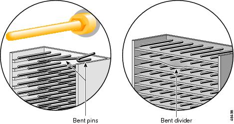
•![]() Inspect the backplane for bent pins or bent dividers between pin rows (see Figure 3-1).
Inspect the backplane for bent pins or bent dividers between pin rows (see Figure 3-1).
If the backplane has bent pins, do not install a card in that slot. Installing a card into a damaged backplane slot will damage the connector on the card.
Figure 3-1 Backplane Inspection Check Points
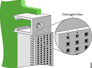
•![]() Inspect the card for damaged holes on the connector (see Figure 3-2).
Inspect the card for damaged holes on the connector (see Figure 3-2).
If the connector has damaged holes, do not install the card. Installing a card that has a damaged connector will damage the backplane. Return damaged cards to Cisco.
Figure 3-2 Damaged Connectors on the Card
Installing the RPM Front Card
Perform the following steps to install the RPM in the MGX 8850 chassis.
Step 1 ![]() Position the rear edge of the card over the appropriate slot card guide at the top and bottom of the cage.
Position the rear edge of the card over the appropriate slot card guide at the top and bottom of the cage.
Note ![]() Verify that the intended slot for the card is the correct slot before you install the card.
Verify that the intended slot for the card is the correct slot before you install the card.
Step 2 ![]() Carefully slide the RPM card all the way into the slot.
Carefully slide the RPM card all the way into the slot.
Step 3 ![]() Press both extractor levers until they snap into the vertical position.
Press both extractor levers until they snap into the vertical position.
Note ![]() The RPM should slide in and out with only slight friction on the adjacent board EMI gaskets. Do not use force. Investigate any binding.
The RPM should slide in and out with only slight friction on the adjacent board EMI gaskets. Do not use force. Investigate any binding.
Removing the RPM Card
Double-height front cards have a latch on the ejector at both the top and the bottom of the front panel.
Warning ![]() To prevent damage to the cards from static electricity, put on a wrist strap and connect it to any convenient metal contact on the system or card cage before you touch any cards.
To prevent damage to the cards from static electricity, put on a wrist strap and connect it to any convenient metal contact on the system or card cage before you touch any cards.
Figure 3-3 Front Card Extractor Latch
Perform the following steps to remove an RPM front card from the MGX 8850 chassis.
Step 1 ![]() Detach all cables from the card.
Detach all cables from the card.
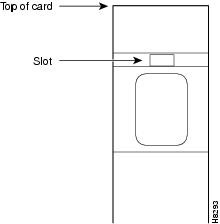
Step 2 ![]() Press the tip of a small, flat-head screwdriver into the slot of the extractor lever (see Figure 3-3); press until the latch springs open, to approximately 10°.
Press the tip of a small, flat-head screwdriver into the slot of the extractor lever (see Figure 3-3); press until the latch springs open, to approximately 10°.
Step 3 ![]() To separate the card from the backplane connector, pull the extractor lever(s) out.
To separate the card from the backplane connector, pull the extractor lever(s) out.
Step 4 ![]() Gently pull the RPM out along the guides. If it sticks, jiggle it gently.
Gently pull the RPM out along the guides. If it sticks, jiggle it gently.
Step 5 ![]() Carefully pull the card out of the card cage. Store it in an anti-static bag.
Carefully pull the card out of the card cage. Store it in an anti-static bag.
Note ![]() The RPM slides along plastic guides into the front of the MGX 8850 system (see Figure 3-4) and connects to the chassis midplane. When removing the RPM, you may feel some resistance as the midplane connector unseats.
The RPM slides along plastic guides into the front of the MGX 8850 system (see Figure 3-4) and connects to the chassis midplane. When removing the RPM, you may feel some resistance as the midplane connector unseats.
Figure 3-4 RPM Installed in the MGX 8850 Chassis (Front View)
Installing and Removing Back Cards in the MGX 8850 Midplane
The following sections describe how to install and remove the Ethernet, Fast Ethernet or FDDI (RPM/B only) back cards from the MGX 8850 midplane.
Installing the Back Cards
Use the following procedure to install the Ethernet, Fast Ethernet or FDDI (RPM/B only) back cards in the MGX 8850 midplane.
Note ![]() Ensure that the two extractor levers are in the "in" position. When the card is being inserted into the slot, the levers should be vertical along the line of the back card.
Ensure that the two extractor levers are in the "in" position. When the card is being inserted into the slot, the levers should be vertical along the line of the back card.
Step 1 ![]() Position the rear card guides over the appropriate slot (directly behind the RPM in the chassis) at the top and bottom of the card cage.
Position the rear card guides over the appropriate slot (directly behind the RPM in the chassis) at the top and bottom of the card cage.
There are two connectors each with 360 pins, for a total of 720 pins. The top and bottom connectors are mechanically identical.
Step 2 ![]() Push the back card firmly but gently into the slot and then all the way into the connectors on the midplane.
Push the back card firmly but gently into the slot and then all the way into the connectors on the midplane.
Note ![]() Correct alignment between connector pins and receptacles is extremely important. First, make sure all pins on the card are straight. Make sure the connector on the card is aligned with the midplane connector. Insert the card gently. It may be necessary to push the card slightly to one side to achieve alignment.
Correct alignment between connector pins and receptacles is extremely important. First, make sure all pins on the card are straight. Make sure the connector on the card is aligned with the midplane connector. Insert the card gently. It may be necessary to push the card slightly to one side to achieve alignment.
Step 3 ![]() Tighten the two captive screws on the back card faceplate.
Tighten the two captive screws on the back card faceplate.
Tighten the upper and lower screws to prevent misalignment of the card. Do not overtighten the screws. Tighten only enough to secure the card.
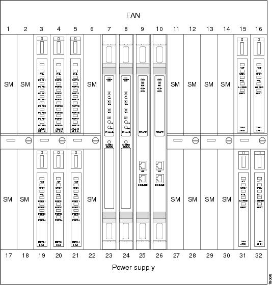
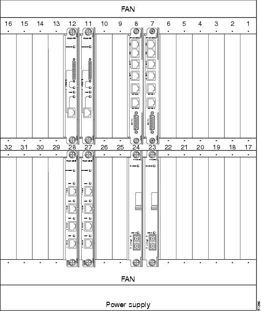
Back cards installed in an MGX 8850 chassis and connected to the midplane are illustrated in Figure 3-5.
Note ![]() Slots 7 and 8 are reserved for the PXM-45 cards occupying the full height of the chassis. You can see PXM-45-UI-S3 cards in the top slots and T3 cards in the bottom slots in Figure 3-5. The illustration shows RPMs in slots 9 and 10 occupying the full height of the chassis. You can see FE and 4E or 4E/B cards in the bottom slots.
Slots 7 and 8 are reserved for the PXM-45 cards occupying the full height of the chassis. You can see PXM-45-UI-S3 cards in the top slots and T3 cards in the bottom slots in Figure 3-5. The illustration shows RPMs in slots 9 and 10 occupying the full height of the chassis. You can see FE and 4E or 4E/B cards in the bottom slots.
FDDI back cards must be installed in the top slot of the RPM/B.
Removing the RPM Back Cards
Use the following procedure to remove the Ethernet or the Fast Ethernet back cards from the MGX 8850 midplane.
Step 1 ![]() Label and detach any cables connected to the back card.
Label and detach any cables connected to the back card.
Step 2 ![]() Use a flat screwdriver to remove the two retaining screws in the back card faceplate.
Use a flat screwdriver to remove the two retaining screws in the back card faceplate.
Step 3 ![]() Pull both extractor levers out to the horizontal position.
Pull both extractor levers out to the horizontal position.
This action will start the removal of the card.
Step 4 ![]() Gently pull the card out of the card cage.
Gently pull the card out of the card cage.
Figure 3-5 RPM Back Cards Connected to a MGX 8850 (Back View)
Connecting a Console Terminal or PC to the RPM Console Port
The RPM includes asynchronous serial console and auxiliary ports. These ports provide administrative access to the RPM either locally using a console terminal, or remotely using a modem.
Use the following procedure to connect a terminal (an ASCII terminal or a PC running terminal emulation software) to the console port on the RPM.
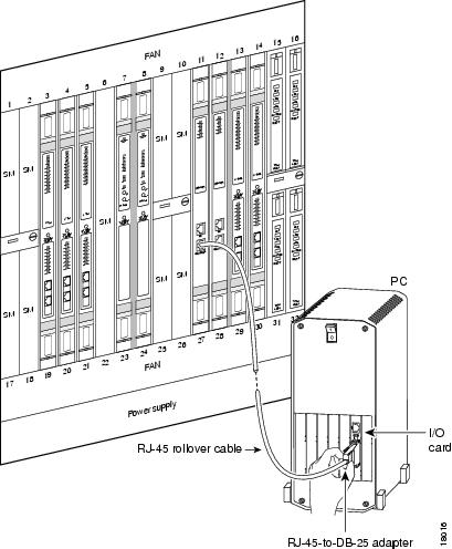
Step 1 ![]() Connect the terminal (see Figure 3-6) using the thin, flat, RJ-45-to-RJ-45 rollover cable (which looks like a telephone cable) and an RJ-45-to-DB-9 or RJ-45-to-DB-25 adapter (labeled "Terminal").
Connect the terminal (see Figure 3-6) using the thin, flat, RJ-45-to-RJ-45 rollover cable (which looks like a telephone cable) and an RJ-45-to-DB-9 or RJ-45-to-DB-25 adapter (labeled "Terminal").
For cable pinouts, see "Cable and Connector Specifications."
Step 2 ![]() Configure your terminal or PC terminal emulation software for 9600 baud, 8 data bits, no parity, and 2 stop bits.
Configure your terminal or PC terminal emulation software for 9600 baud, 8 data bits, no parity, and 2 stop bits.
Note ![]() The default parameters for the internal console port on the RPM are 9600 baud, 8 data bits, no parity and 2 stop bits.
The default parameters for the internal console port on the RPM are 9600 baud, 8 data bits, no parity and 2 stop bits.
Figure 3-6 Connecting a Console Terminal to the RPM Console Port
Connecting a Modem to the Auxiliary Port
Use the following procedure to connect a modem to the auxiliary port on the RPM for remote access.
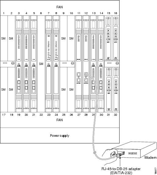
Step 1 ![]() Connect a modem (see Figure 3-7) to the auxiliary port (labelled "Aux") using the thin, flat, RJ-45-to-RJ-45 rollover cable, which looks like a telephone cable, with the RJ-45-to-DB-25 adapter (labeled "Modem").
Connect a modem (see Figure 3-7) to the auxiliary port (labelled "Aux") using the thin, flat, RJ-45-to-RJ-45 rollover cable, which looks like a telephone cable, with the RJ-45-to-DB-25 adapter (labeled "Modem").
Step 2 ![]() Make sure that the modem and the auxiliary port on the RPM are configured for the same transmission speed (38,400 baud is maximum) and hardware flow control.
Make sure that the modem and the auxiliary port on the RPM are configured for the same transmission speed (38,400 baud is maximum) and hardware flow control.
Figure 3-7 Connecting a Modem to the Auxiliary Port on the RPM
When the RPM is installed in the MGX 8850, make sure the system is powered on. Proceed to "Cabling the MGX RPM Back Cards."
Upgrading from an RPM/B Card to an RPM-PR Card
To replace an RPM/B card with an RPM-PR card, the PXM must be running MGX Software Release 1.1.34 or later, and the RPM must be running IOS release 12.2(4)T or later. Then perform the following procedure.
Step 1 ![]() Insert the RPM-PR in a test node.
Insert the RPM-PR in a test node.
Step 2 ![]() Copy the new RPM-PR boot image to the flash. Verify that the boot image is the first file in the flash.
Copy the new RPM-PR boot image to the flash. Verify that the boot image is the first file in the flash.
Step 3 ![]() Modify the configuration of the file to use the latest IOS image on the c: drive by entering the boot system c:<IOS_filename> command.
Modify the configuration of the file to use the latest IOS image on the c: drive by entering the boot system c:<IOS_filename> command.
Step 4 ![]() Enter the write memory command to save the configuration file in NVRAM.
Enter the write memory command to save the configuration file in NVRAM.
Step 5 ![]() Enter the show bootvar command to check the BOOT variable and to verify that the card us configured to boot from the latest image.
Enter the show bootvar command to check the BOOT variable and to verify that the card us configured to boot from the latest image.
Now the RPM-PR card is ready to replace an RPM/B card.
Step 6 ![]() Verify the following before inserting the RPM-PR in the node:
Verify the following before inserting the RPM-PR in the node:
•![]() PXM must be running a minimum firmware release of 1.1.34.
PXM must be running a minimum firmware release of 1.1.34.
•![]() PXM disk contains the latest IOS image specified for the RPM-PR.
PXM disk contains the latest IOS image specified for the RPM-PR.

 Feedback