Diagnosing Problems
The switch LEDs provide troubleshooting information about the switch. They show boot fast failures, port-connectivity problems, and overall switch performance. You can also get statistics from Device Manager, the CLI, or an SNMP workstation. See the Cisco IE 2000 Switch Software Configuration Guide , the Cisco IE 2000 Switch Command Reference on Cisco.com, or the documentation that came with your SNMP application for details.
Bad or Damaged Cable
Examine the cable for marginal damage or failure. A cable might be just good enough to connect at the physical layer, but it could corrupt packets as a result of subtle damage to the wiring or connectors. You can identify this problem because the port has many packet errors or it constantly flaps (loses and regains link).
- Exchange the cable with a known good cable.
- Look for broken or missing pins on cable connectors.
- Rule out any bad patch panel connections or media converters between the source and the destination. If possible, bypass the patch panel.
- Try the cable in another port to see if the problem follows the cable.
Link Status
Verify that both sides have a link. A broken wire or a shutdown port can cause one side to show a link even though the other side does not have a link.
A port LED that is on does not guarantee that the cable is functional. It might have encountered physical stress, causing it to function at a marginal level. If the port LED does not turn on:
- Connect the cable from the switch to a known good device.
- Make sure that both ends of the cable are connected to the correct ports.
- Verify that both devices have power.
- Verify that you are using the correct cable type.
- Look for loose connections. Sometimes a cable appears to be seated but is not. Disconnect the cable, and then reconnect it.
Interface Settings
Verify that the interface is not disabled or powered off. If an interface is manually shut down on either side of the link, it does not come up until you reenable the interface. Use the show interfaces privileged EXEC command to see if the interface is error-disabled, disabled, or shut down on either side of the connection. If needed, reenable the interface.
Ping End Device
Ping from the directly connected switch first, and then work your way back port by port, interface by interface, trunk by trunk, until you find the source of the connectivity issue. Make sure that each switch can identify the end device MAC address in its Content-Addressable Memory (CAM) table.
Spanning Tree Loops
STP loops can cause serious performance issues that look like port or interface problems.
A unidirectional link can cause loops. It occurs when the traffic sent by the switch is received by the neighbor, but notification that the traffic was received from the neighbor is not received by the switch. A broken cable, other cabling problems, or a port issue can cause this one-way communication.
You can enable UniDirectional Link Detection (UDLD) on the switch to help identify unidirectional link problems. For information about enabling UDLD on the switch, see the “Information About UDLD” section in the Cisco IE 2000 Switch Software Configuration Guide on Cisco.com.
Speed, Duplex, and Autonegotiation
Port statistics that show a large amount of alignment errors, frame check sequence (FCS), or late-collisions errors, a common issue when duplex and speed settings are mismatched between two devices.
To maximize switch performance and to ensure a link, follow one of these guidelines when changing the duplex or the speed settings.
- Let both ports autonegotiate both speed and duplex.
- Manually set the speed and duplex parameters for the interfaces on both ends of the connection.
- If a remote device does not autonegotiate, use the same duplex settings on the two ports. The speed parameter adjusts itself even if the connected port does not autonegotiate.
Autonegotiation and Network Interface Cards
Problems sometimes occur between the switch and third-party network interface cards (NICs). By default, the switch ports and interfaces autonegotiate. Laptops or other devices are commonly set to autonegotiate, yet sometimes issues occur.
ITo troubleshoot autonegotiation problems, try manually setting both sides of the connection to the same speed and duplex mode. If this does not solve the problem, there could be a problem with the firmware or software on the NIC. You might resolve this by upgrading the NIC driver to the latest version.
Cabling Distance
If the port statistics show excessive FCS, late-collision, or alignment errors, verify that the cable distance from the switch to the connected device meets the recommended guidelines.
Resetting the Switch
Resetting the switch deletes the configuration and reboots the switch.
Reasons why you might want to reset the switch to the factory default settings include:
- You installed the switch in your network and cannot connect to it because it is assigned an unknown IP address.
- You want to reset the password on the switch.

Note The Cisco iOS firmware is stored in the Flash memory on the device; the Cisco iOS firmware is not installed on the SD memory card.

Step 1 Press and hold the Express Setup button for 10 seconds or more. The switch reboots. The system LED turns green after the switch completes rebooting.
Step 2 Press the Express Setup button again for 3 seconds. A switch 10/100 Ethernet port blinks green.
The switch now behaves like a factory-default configured switch.
How to Recover Passwords
Password recovery is a feature that a system administrator can enable or disable. If password recovery is disabled, the only way to recover from a lost or forgotten password is to clear the switch configuration entirely. For this procedure, see the “Resetting the Switch” section.
The Cisco IE 2000 Switch Software Configuration Guide provides details about enabling and disabling the password recovery feature and the procedure for recovering passwords.
Troubleshooting Express Setup
This section provides troubleshooting tips for the initial switch configuration.
Finding the Switch Serial Number
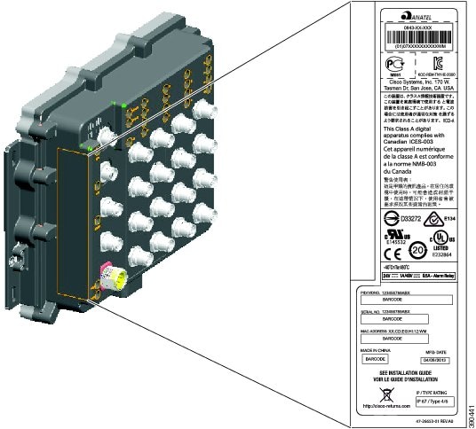
If you contact Cisco Technical Assistance, you need to know the serial number of your switch. The serial number is on the compliance label on the right-hand side of the switch. See Figure 4-1. You can also use the show version privileged EXEC command to obtain the switch serial number.
Figure 4-1 Serial Number Location for the Cisco IE 2000 IP67 Series Switches
 Feedback