Product Overview
This switch provides a rugged and secure switching infrastructure for harsh environments. It is suitable for industrial Ethernet applications, including factory automation, intelligent transportation systems (ITSs), substations, oil and gas installations, and other deployments in harsh environments.
You can connect this switch to office networking devices such as Cisco IP phones, Cisco Wireless Access Points, and other devices such as servers, routers, and other switches. In industrial environments, you can connect any Ethernet-enabled industrial communication device, including programmable logic controllers (PLCs), human-machine interfaces (HMIs), drives, sensors, video devices, traffic signal controllers, and intelligent electronic devices (IEDs).
This switch also has Power over Ethernet ports and is IP67 certified.
The switch is wall mounted and its components are designed to withstand extremes in temperature, vibration, and shock that are common in an industrial environment.

Note![]() Installation details are provided in the Switch Installation section.
Installation details are provided in the Switch Installation section.
Most of the documentation related to this product can be found at http://www.cisco.com/en/US/products/ps12451/tsd_products_support_series_home.html
Switch Models and Power Supply
Figure 1-1 Industrial Ethernet 2000 IP67 Series

Table 1-1 lists and describes the switches and power supply. All IP67 switches use the LAN Base Cisco iOS firmware.
Front Panel of the Switch
This section describes the front panel components. The following figures depict the components available on the various models in this product family. Not all models are illustrated.
Figure 1-2 Cisco IE 2000 IP67 Series Switch (16port with 8 PoE ports Model Shown) Front Panel View
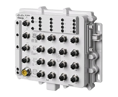
10/100BASE-T Downlink Ports
You can set the 10/100BASE-T downlink ports to operate at 10 or 100 Mb/s over IP standard M12 cabling. The ports can operate in full-duplex, half-duplex, autonegotiate (default), or never half-duplex mode.
A Never Half Duplex option for a port functions as the name implies, the link is never established at half duplex; it is either full-duplex or no link. Never Half Duplex avoids the unpredictable response times that in a CSMA/CD network can cause safety features to trip or interruptions that require restarting the process flow.

|
|
|
||
|
|
4 |
The 10/100BASE-T ports 1 to 4 on a 8 port switch and 10/100BASE-T ports 1 to 8 on a 16 port switch support PoE (IEEE802.3af) by default. Ports 1 to 4 on a 8 port switch or 1 to 8 on a 16 port switch can be configured to operate as PoE+ (IEEE802.3at) ports. The switch supports a total of 120W power on the PoE ports with any combination of PoE or PoE+ feature on ports 1 to 8. IEEE standards require that the PSE (switch) supports a maximum of 15400 mW per port for PoE ports and 30000 mW per port for PoE+ ports. To meet the maximum load requirement on the switch when operating with 8 PoE or 4 PoE+ ports, a power source rated at 54V, 160W should be used. The source power rating will be lower for configurations requiring lesser than 4 PoE+ or 8 PoE ports.
You can use the Device Manager or the sh power inline consumption default wattage command to change the configured power consumption values.
When the power requirement of a connected device is known and less than the maximum value for the class, the wattage can be set lower than the default IEEE classification. This setting overrides both the IEEE classification and power negotiation. For example, an IP phone that requires only 5 W but is in Class 0, which allows a maximum of 15.4 W. Configuring an override that reduces power on this port makes more power available to other ports. See the Cisco IE 2000 Switch Command Reference for more information. Class 0–3 is PoE. Class 4 is PoE+:
|
|
|
|---|---|
10/100/1000BASE-T Uplink Ports
The IEEE 802.3u 10/100/1000BASE-T uplink ports provide 10, 100 or 1000 Mb/s connectivity over IP standard M12 X Coded shielded cabling. The ports can operate in full-duplex, half-duplex, autonegotiate (default), or never half-duplex mode. The default setting is autonegotiate.
|
|
|
||
|
|
6 |
||
|
|
7 |
||
4 |
8 |
Power Connector
You connect the DC power to the switch through the front panel connector. The power connector labeling is on the panel. Torque power connection to 10in/lbs.
The switch can operate with a single power source or with dual power sources. When both power sources are operational, the switch draws power from the DC source with the higher voltage. If one of the two power sources fail, the other continues to power the switch.
Additional information regarding the power levels is available in the Power-over-Ethernet section of this chapter.

|
|
|
||
|
|
4 |
Alarm Connector
You connect the alarm signals to the switch through the alarm connector. The switch supports one alarm output relay.
The alarm output circuit is a relay with a normally open and a normally closed contact. The switch is configured to detect faults that are used to energize the relay coil and change the state on both of the relay contacts: normally open contacts close, and normally closed contacts open. The alarm output relay can be used to control an external alarm device, such as a bell or a light.

|
|
|
||
|
|
5 |
||
|
|
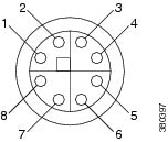
Console Management Port
You can connect the switch to a PC running Microsoft Windows or to a terminal server through the 5-pole A-coded console port and configure it by using the CLI. The baud rate and format of the console port is:
|
|
|
||
|
|
5 |
||
|
|
Note![]() For specified cable, use Molex part number: 120076-0628
For specified cable, use Molex part number: 120076-0628
LEDs
You can use the LEDs to monitor overall system status and power supply input and output status as well as port and alarm status.
Express Setup LED
The Express Setup LED displays the status of the initial setup for the initial configuration.
PoE Status LED
The PoE LED indicates the status of the PoE ports.

Port Status LEDs
Each 10/100BASE-T downlink port (identified by numbers 1-24, depending on the model) and 10/100/1000BASE-T uplink port (identified as GE-1 and GE-2) has a port status LED.
System LED
The System LED shows whether the device is receiving power and is functioning properly.
Alarm LEDs
Table 1-6 list the alarm LED colors and their meanings.
Power Status LEDs
The switch can operate with one or two DC power sources marked DC_A and DC_B. Each DC input has an associated LED that shows the status of the corresponding DC input. If power is present on the circuit, the LED is green. If power is not present, the LED color depends on the alarm configuration. If alarms are configured, the LED is red when power is not present; otherwise, the LED is off.
If the switch has dual power sources, the switch draws power from the power source with the higher voltage. If one of the DC sources fails, the alternate DC source powers the switch, and the corresponding power status LED is green. The power status for the failed DC source is either off or red, depending on the alarm configuration.
For information about the power LED colors and behaviors during the boot fast sequence, see the “LEDs” section.
Rear Panel
The rear panels of the switch and the IP67 power supply have 4 mounting ears for installation on wall.
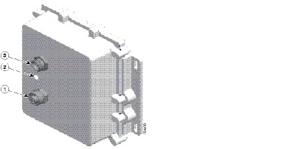
IP67 Power Supply
The switch is offered with an optional IP67 DC-DC power supply (PWR-IE160W-67-DC=). The IP67 DC-DC power supply can take 18 to 60Vdc input and provide a 54V, 160W DC output sufficient to run the IP67 ie2000 switch with up to 8 PoE ports (or 4 PoE+) ports. There are also non-IP67 power supplies compatible with the switch.
Note![]() The power supply (PWR-IE160W-67-DC=) is sold separately.
The power supply (PWR-IE160W-67-DC=) is sold separately.
Figure 1-8 displays the IP67 Power Supply.
Figure 1-8 Cisco IP67 Power Supply
1 |
3 |
||
2 |
 Feedback