- Release 15.4SY Supervisor Engine 6T Software Configuration Guide
- Preface
- Product Overview
- Command-Line Interfaces
- Smart Port Macros
- Virtual Switching Systems (VSS)
- Enhanced Fast Software Upgrade (eFSU)
- Fast Software Upgrades
- Stateful Switchover (SSO)
- Non-Stop Forwarding (NSF)
- RPR Supervisor Engine Redundancy
- Interface Configuration
- UniDirectional Link Detection (UDLD)
- Instant Access
- EnergyWise
- Power Management
- Environmental Monitoring
- Online Diagnostics
- Onboard Failure Logging (OBFL)
- Switch Fabric Functionality
- Cisco IP Phone Support
- Power over Ethernet
- Layer 2 LAN Port Configuration
- Flex Links
- EtherChannels
- IEEE 802.1ak MVRP and MRP
- VLAN Trunking Protocol (VTP)
- VLANs
- Private VLANs (PVLANs)
- Private Hosts
- IEEE 802.1Q Tunneling
- Layer 2 Protocol Tunneling
- Spanning Tree Protocols (STP, MST)
- Optional STP Features
- IP Unicast Layer 3 Switching
- Policy Based Routing (PBR)
- Layer 3 Interface Configuration
- Unidirectional Ethernet (UDE) and unidirectional link routing (UDLR)
- Multiprotocol Label Switching (MPLS)
- MPLS VPN Support
- Ethernet over MPLS (EoMPLS)
- L2VPN Advanced VPLS (A-VPLS)
- Ethernet Virtual Connections (EVC)
- Layer 2 over Multipoint GRE (L2omGRE)
- Campus Fabric
- IPv4 Multicast Layer 3 Features
- IPv4 Multicast IGMP Snooping
- IPv4 PIM Snooping
- IPv4 Multicast VLAN Registration (MVR)
- IPv4 IGMP Filtering
- IPv4 Router Guard
- IPv4 Multicast VPN Support
- IPv6 Multicast Layer 3 Features
- IPv6 MLD Snooping
- NetFlow Hardware Support
- System Event Archive (SEA)
- Backplane Platform Monitoring
- Local SPAN, RSPAN, and ERSPAN
- SNMP IfIndex Persistence
- Top-N Reports
- Layer 2 Traceroute Utility
- Mini Protocol Analyzer
- PFC QoS Guidelines and Restrictions
- PFC QoS Overview
- PFC QoS Classification, Marking, and Policing
- PFC QoS Policy Based Queueing
- PFC QoS Global and Interface Options
- AutoQoS
- MPLS QoS
- PFC QoS Statistics Data Export
- Cisco IOS ACL Support
- Cisco TrustSec (CTS)
- AutoSecure
- MAC Address-Based Traffic Blocking
- Port ACLs (PACLs)
- VLAN ACLs (VACLs)
- Policy-Based Forwarding (PBF)
- Denial of Service (DoS) Protection
- Control Plane Policing (CoPP)
- Dynamic Host Configuration Protocol (DHCP) Snooping
- IP Source Guard
- Dynamic ARP Inspection (DAI)
- Traffic Storm Control
- Unknown Unicast and Multicast Flood Control
- IEEE 802.1X Port-Based Authentication
- Configuring Web-Based Authentication
- Port Security
- Lawful Intercept
- Online Diagnostic Tests
Release 15.4SY Supervisor Engine 6T Software Configuration Guide
Bias-Free Language
The documentation set for this product strives to use bias-free language. For the purposes of this documentation set, bias-free is defined as language that does not imply discrimination based on age, disability, gender, racial identity, ethnic identity, sexual orientation, socioeconomic status, and intersectionality. Exceptions may be present in the documentation due to language that is hardcoded in the user interfaces of the product software, language used based on RFP documentation, or language that is used by a referenced third-party product. Learn more about how Cisco is using Inclusive Language.
- Updated:
- August 14, 2014
Chapter: MPLS VPN Support
MPLS VPN Support
- Prerequisites for MPLS VPN
- Restrictions for MPLS VPN
- Information About MPLS VPN Support
- How to Configure MPLS VPNs
- Configuration Example for MPLS VPNs

Note ●![]() For complete syntax and usage information for the commands used in this chapter, see these publications:
For complete syntax and usage information for the commands used in this chapter, see these publications:
http://www.cisco.com/en/US/products/ps11846/prod_command_reference_list.html
- Cisco IOS Release 15.4SY supports only Ethernet interfaces. Cisco IOS Release 15.4SY does not support any WAN features or commands.
http://www.cisco.com/en/US/products/hw/switches/ps708/tsd_products_support_series_home.html
Participate in the Technical Documentation Ideas forum
Prerequisites for MPLS VPN
Restrictions for MPLS VPN
- When configuring MPLS VPN, note that VPNs are recirculated when the number of VPNs is over 511.
- MPLS VPN supports these commands:
For information about these commands, see these publications:
http://www.cisco.com/en/US/products/ps11846/prod_command_reference_list.html
Cisco IOS Release 15.4SY supports only Ethernet interfaces. Cisco IOS Release 15.4SY does not support any WAN features or commands.
Information About MPLS VPN Support
The IP VPN feature for MPLS allows a Cisco IOS network to deploy scalable IP Layer 3 VPN backbone services to multiple sites deployed on a shared infrastructure while also providing the same access or security policies as a private network. VPN based on MPLS technology provides the benefits of routing isolation and security, as well as simplified routing and better scalability. See this publication for more information about MPLS VPNs:
http://www.cisco.com/en/US/docs/ios-xml/ios/mpls/config_library/15-sy/mp-15-sy-library.html
Figure 38-1 VPNs with MPLS Service Provider Backbone
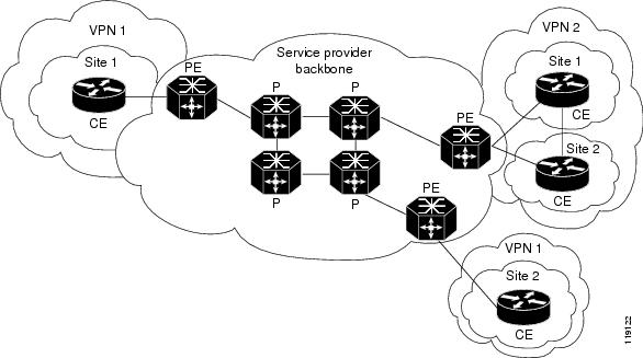
At the ingress PE, the PFC makes a forwarding decision based on the packet headers. The PFC contains a table that maps VLANs to VPNs. In the switch architecture, all physical ingress interfaces in the system are associated with a specific VPN. The PFC looks up the IP destination address in the CEF table but only against prefixes that are in the specific VPN. (The table entry points to a specific set of adjacencies and one is chosen as part of the load-balancing decision if multiple parallel paths exist.)
The table entry contains the information on the Layer 2 header that the packet needs, as well as the specific MPLS labels to be pushed onto the frame. The information to rewrite the packet goes back to the ingress module where it is rewritten and forwarded to the egress line interface.
VPN traffic is handled at the egress from the PE based upon the per-prefix labels or aggregate labels. If per-prefix labels are used, then each VPN prefix has a unique label association; this allows the PE to forward the packet to the final destination based upon a label lookup in the FIB.
Note![]() The PFC allocates only one aggregate label per VRF.
The PFC allocates only one aggregate label per VRF.
If aggregate labels are used for disposition in an egress PE, many prefixes on the multiple interfaces may be associated with the label. In this case, the PFC must perform an IP lookup to determine the final destination. The IP lookup may require recirculation.
How to Configure MPLS VPNs
For information on configuring MPLS VPN, see tis publication:
http://www.cisco.com/en/US/docs/ios-xml/ios/mpls/config_library/15-sy/mp-15-sy-library.html
Note![]() If you use a Layer 3 VLAN interface as the MPLS uplink through a Layer 2 port peering with another MPLS device, then you can use another Layer 3 VLAN interface as the VRF interface.
If you use a Layer 3 VLAN interface as the MPLS uplink through a Layer 2 port peering with another MPLS device, then you can use another Layer 3 VLAN interface as the VRF interface.
Configuration Example for MPLS VPNs
This sample configuration shows LAN CE-facing interfaces. MPLS switching configuration in Cisco IOS Release 15.4SY is identical to configuration in other releases.
 Feedback