- Release 15.4SY Supervisor Engine 2T Software Configuration Guide
- Preface
- Product Overview
- Command-Line Interfaces
- Smart Port Macros
- Virtual Switching Systems (VSS)
- Enhanced Fast Software Upgrade (eFSU)
- Fast Software Upgrades
- Stateful Switchover (SSO)
- Non-Stop Forwarding (NSF)
- RPR Supervisor Engine Redundancy
- Interface Configuration
- UniDirectional Link Detection (UDLD)
- Instant Access
- EnergyWise
- Power Management
- Environmental Monitoring
- Online Diagnostics
- Onboard Failure Logging (OBFL)
- Switch Fabric Functionality
- Cisco IP Phone Support
- Power over Ethernet
- Layer 2 LAN Port Configuration
- Flex Links
- EtherChannels
- IEEE 802.1ak MVRP and MRP
- VLAN Trunking Protocol (VTP)
- VLANs
- Private VLANs (PVLANs)
- Private Hosts
- IEEE 802.1Q Tunneling
- Layer 2 Protocol Tunneling
- Spanning Tree Protocols (STP, MST)
- Optional STP Features
- IP Unicast Layer 3 Switching
- Policy Based Routing (PBR)
- Layer 3 Interface Configuration
- Unidirectional Ethernet (UDE) and unidirectional link routing (UDLR)
- Multiprotocol Label Switching (MPLS)
- MPLS VPN Support
- Ethernet over MPLS (EoMPLS)
- L2VPN Advanced VPLS (A-VPLS)
- Ethernet Virtual Connections (EVC)
- Layer 2 over Multipoint GRE (L2omGRE)
- Campus Fabric
- IPv4 Multicast Layer 3 Features
- IPv4 Multicast IGMP Snooping
- IPv4 PIM Snooping
- IPv4 Multicast VLAN Registration (MVR)
- IPv4 IGMP Filtering
- IPv4 Router Guard
- IPv4 Multicast VPN Support
- IPv6 Multicast Layer 3 Features
- IPv6 MLD Snooping
- NetFlow Hardware Support
- Call Home
- System Event Archive (SEA)
- Backplane Platform Monitoring
- Local SPAN, RSPAN, and ERSPAN
- SNMP IfIndex Persistence
- Top-N Reports
- Layer 2 Traceroute Utility
- Mini Protocol Analyzer
- PFC QoS Guidelines and Restrictions
- PFC QoS Overview
- PFC QoS Classification, Marking, and Policing
- PFC QoS Policy Based Queueing
- PFC QoS Global and Interface Options
- AutoQoS
- MPLS QoS
- PFC QoS Statistics Data Export
- Cisco IOS ACL Support
- Cisco TrustSec (CTS)
- AutoSecure
- MAC Address-Based Traffic Blocking
- Port ACLs (PACLs)
- VLAN ACLs (VACLs)
- Policy-Based Forwarding (PBF)
- Denial of Service (DoS) Protection
- Control Plane Policing (CoPP)
- Dynamic Host Configuration Protocol (DHCP) Snooping
- IP Source Guard
- Dynamic ARP Inspection (DAI)
- Traffic Storm Control
- Unknown Unicast Flood Control
- IEEE 802.1X Port-Based Authentication
- Configuring Web-Based Authentication
- Port Security
- Lawful Intercept
Flex Links
- Prerequisites for Flex Links
- Restrictions for Flex Links
- Information About Flex Links
- Default Settings for Flex Links
- How to Configure Flex Links
- Monitoring Flex Links

Note ●![]() For complete syntax and usage information for the commands used in this chapter, see these publications:
For complete syntax and usage information for the commands used in this chapter, see these publications:
http://www.cisco.com/en/US/products/ps11846/prod_command_reference_list.html
- Cisco IOS Release 15.4SY supports only Ethernet interfaces. Cisco IOS Release 15.4SY does not support any WAN features or commands.
http://www.cisco.com/en/US/products/hw/switches/ps708/tsd_products_support_series_home.html
Participate in the Technical Documentation Ideas forum
Prerequisites for Flex Links
Restrictions for Flex Links
- You can configure only one Flex Links backup link for any active link, and it must be a different interface from the active interface.
- An interface can belong to only one Flex Links pair. An interface can be a backup link for only one active link. An active link cannot belong to another Flex Links pair.
- Neither of the links can be a port that belongs to an EtherChannel. However, you can configure two port channels (EtherChannel logical interfaces) as Flex Links, and you can configure a port channel and a physical interface as Flex Links, with either the port channel or the physical interface as the active link.
- A backup link does not have to be the same type as the active link (Fast Ethernet, Gigabit Ethernet, or port channel). However, you should configure both Flex Links with similar characteristics so that there are no loops or changes in operation if the standby link becomes active.
- STP is disabled on Flex Links ports. If STP is disabled on the switch, be sure that there are no Layer 2 loops in the network topology.
- Do not configure any STP features (for example, PortFast, BPDU Guard, and so forth) on Flex Links ports or the ports to which the links connect.
- Local administrative shut down or a link that starts forwarding again due to preemption is not considered a link failure. In those cases, the feature flushes the dynamic hosts and and does not move them.
- Static MAC addresses that are configured on the primary link are not moved to the standby link.
- Static MAC addresses configured on a flex links port are restored when it starts forwarding again.
Information About Flex Links
Flex Links are a pair of Layer 2 interfaces (ports or port channels), where one interface is configured to act as a backup to the other. Flex Links are typically configured in service-provider or enterprise networks where customers do not want to run STP. Flex Links provide link-level redundancy that is an alternative to Spanning Tree Protocol (STP). STP is automatically disabled on Flex Links interfaces.
Release 15.2SY supports a maximum of 16 Flex Links. Flex Links are supported only on Layer 2 ports and port channels, not on VLANs or on Layer 3 ports.
To configure the Flex Links feature, you configure one Layer 2 interface as the standby link for the link that you want to be primary. With Flex Links configured for a pair of interfaces, only one of the interfaces is in the linkup state and is forwarding traffic. If the primary link shuts down, the standby link starts forwarding traffic. When the inactive link comes back up, it goes into standby mode.
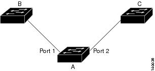
In Figure 23-1, ports 1 and 2 on switch A are connected to uplink switches B and C. Because they are configured as Flex Links, only one of the interfaces is forwarding traffic and the other one is in standby mode. If port 1 is the active link, it begins forwarding traffic between port 1 and switch B; the link between port 2 (the backup link) and switch C is not forwarding traffic. If port 1 goes down, port 2 comes up and starts forwarding traffic to switch C. When port 1 comes back up, it goes into standby mode and does not forward traffic; port 2 continues to forward traffic.
Figure 23-1 Flex Links Configuration Example

If a primary (forwarding) link goes down, a trap notifies the network management stations. If the standby link goes down, a trap notifies the users.When a primary link fails, the feature takes these actions:
- Detects the failure.
- Moves any dynamic unicast MAC addresses that are learned on the primary link to the standby link.
- Moves the standby link to a forwarding state.
- Transmits dummy multicast packets over the new active interface. The dummy multicast packet format is:
–![]() Destination: 01:00:0c:cd:cd:cd
Destination: 01:00:0c:cd:cd:cd
–![]() Source: MAC address of the hosts or ports on the newly active Flex Link port.
Source: MAC address of the hosts or ports on the newly active Flex Link port.
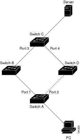
In Figure 23-2, ports 1 and 2 on switch A are connected to switches B and D through a Flex Link pair. Port 1 is forwarding traffic, and port 2 is in the blocking state. Traffic from the PC to the server is forwarded from port 1 to port 3. The MAC address of the PC has been learned on port 3 of switch C. Traffic from the server to the PC is forwarded from port 3 to port 1.
If port 1 shuts down, port 2 starts forwarding traffic. If there is no traffic from the PC to the server after failover to port 2, switch C does not learn the MAC address of the PC on port 4, and because of that, switch C keeps forwarding traffic from the server to the PC out of port 3. There is traffic loss from the server to the PC because port 1 is down. To alleviate this problem, the feature sends out a dummy multicast packet with the source MAC address of the PC over port 2. Switch C learns the PC MAC address on port 4 and start forwarding traffic from the server to the PC out of port 4. One dummy multicast packet is sent out for every MAC address.
Flex links interface preemption specifies one of the ports in a flex links pair as preferred for traffic forwarding. The preference can be unconditional or it can be based on bandwidth availability. See the “How to Configure Flex Links” section.
Figure 23-2 Flexlink Dummy Multicast Packets Example

Default Settings for Flex Links
How to Configure Flex Links
To configure Flex Links, perform this task:
This example shows how to configure an interface with a flex links backup interface and how to verify the configuration:
Monitoring Flex Links
To monitor the Flex Links configuration, perform this task:
http://www.cisco.com/en/US/products/hw/switches/ps708/tsd_products_support_series_home.html
Participate in the Technical Documentation Ideas forum
 Feedback