Installation and Configuration Note for Cisco Catalyst 4500 E-Series Supervisor Engine 9-E
Product Numbers: WS-X45-SUP9-E, WS-X45-SUP9-E=(Spare), WS-X45-SUP9-E/2(Redundant Supervisor)
This document describes the features of the Cisco Catalyst 4500 E-Series Supervisor Engine 9-E and provides information about how to correctly install and remove or replace the module.
|
Compatibility Information |
Description |
|---|---|
|
Chassis compatibility |
Cisco Catalyst 4500 E-Series Supervisor Engine 9-E is supported on the Catalyst 4503-E, Catalyst 4506-E, and Catalyst 4507R+E, Catalyst 4510R+E switch chassis. |
|
Minimum software requirements |
Cisco IOS XE Release 3.10.0E and ROMMON IOS Version 15.1(1r)SG14. For the latest software release requirements, refer to the Cisco IOS Release Notes for the Catalyst 4500-E Series Switches at this location:http://www.cisco.com/c/en/us/support/switches/catalyst-4500-series-switches/products-release-notes-list.html . |
|
Chassis slot restrictions |
|
|
Bandwidth per slot |
48 Gbps per slot—on all supported chassis. |
Statement 1071—Warning Definition
|
IMPORTANT SAFETY INSTRUCTIONS This warning symbol means danger. You are in a situation that could cause bodily injury. Before you work on any equipment, be aware of the hazards involved with electrical circuitry and be familiar with standard practices for preventing accidents. Use the statement number provided at the end of each warning to locate its translation in the translated safety warnings that accompanied this device. Statement 1071 SAVE THESE INSTRUCTIONS |
|
|
Waarschuwing |
BELANGRIJKE VEILIGHEIDSINSTRUCTIES Dit waarschuwingssymbool betekent gevaar. U verkeert in een situatie die lichamelijk letsel kan veroorzaken. Voordat u aan enige apparatuur gaat werken, dient u zich bewust te zijn van de bij elektrische schakelingen betrokken risico's en dient u op de hoogte te zijn van de standaard praktijken om ongelukken te voorkomen. Gebruik het nummer van de verklaring onderaan de waarschuwing als u een vertaling van de waarschuwing die bij het apparaat wordt geleverd, wilt raadplegen. BEWAAR DEZE INSTRUCTIES |
|
Varoitus |
TÄRKEITÄ TURVALLISUUSOHJEITA Tämä varoitusmerkki merkitsee vaaraa. Tilanne voi aiheuttaa ruumiillisia vammoja. Ennen kuin käsittelet laitteistoa, huomioi sähköpiirien käsittelemiseen liittyvät riskit ja tutustu onnettomuuksien yleisiin ehkäisytapoihin. Turvallisuusvaroitusten käännökset löytyvät laitteen mukana toimitettujen käännettyjen turvallisuusvaroitusten joukosta varoitusten lopussa näkyvien lausuntonumeroiden avulla. SÄILYTÄ NÄMÄ OHJEET |
|
Attention |
IMPORTANTES INFORMATIONS DE SÉCURITÉ Ce symbole d'avertissement indique un danger. Vous vous trouvez dans une situation pouvant entraîner des blessures ou des dommages corporels. Avant de travailler sur un équipement, soyez conscient des dangers liés aux circuits électriques et familiarisez-vous avec les procédures couramment utilisées pour éviter les accidents. Pour prendre connaissance des traductions des avertissements figurant dans les consignes de sécurité traduites qui accompagnent cet appareil, référez-vous au numéro de l'instruction situé à la fin de chaque avertissement. CONSERVEZ CES INFORMATIONS |
|
Warnung |
WICHTIGE SICHERHEITSHINWEISE Dieses Warnsymbol bedeutet Gefahr. Sie befinden sich in einer Situation, die zu Verletzungen führen kann. Machen Sie sich vor der Arbeit mit Geräten mit den Gefahren elektrischer Schaltungen und den üblichen Verfahren zur Vorbeugung vor Unfällen vertraut. Suchen Sie mit der am Ende jeder Warnung angegebenen Anweisungsnummer nach der jeweiligen Übersetzung in den übersetzten Sicherheitshinweisen, die zusammen mit diesem Gerät ausgeliefert wurden. BEWAHREN SIE DIESE HINWEISE GUT AUF. |
|
Avvertenza |
IMPORTANTI ISTRUZIONI SULLA SICUREZZA Questo simbolo di avvertenza indica un pericolo. La situazione potrebbe causare infortuni alle persone. Prima di intervenire su qualsiasi apparecchiatura, occorre essere al corrente dei pericoli relativi ai circuiti elettrici e conoscere le procedure standard per la prevenzione di incidenti. Utilizzare il numero di istruzione presente alla fine di ciascuna avvertenza per individuare le traduzioni delle avvertenze riportate in questo documento. CONSERVARE QUESTE ISTRUZIONI |
|
Advarsel |
VIKTIGE SIKKERHETSINSTRUKSJONER Dette advarselssymbolet betyr fare. Du er i en situasjon som kan føre til skade på person. Før du begynner å arbeide med noe av utstyret, må du være oppmerksom på farene forbundet med elektriske kretser, og kjenne til standardprosedyrer for å forhindre ulykker. Bruk nummeret i slutten av hver advarsel for å finne oversettelsen i de oversatte sikkerhetsadvarslene som fulgte med denne enheten. TA VARE PÅ DISSE INSTRUKSJONENE |
|
Aviso |
INSTRUÇÕES IMPORTANTES DE SEGURANÇA . Este símbolo de aviso significa perigo. Você está em uma situação que poderá ser causadora de lesões corporais. Antes de iniciar a utilização de qualquer equipamento, tenha conhecimento dos perigos envolvidos no manuseio de circuitos elétricos e familiarize-se com as práticas habituais de prevenção de acidentes. Utilize o número da instrução fornecido ao final de cada aviso para localizar sua tradução nos avisos de segurança traduzidos que acompanham este dispositivo GUARDE ESTAS INSTRUÇÕES |
|
¡Advertencia! |
INSTRUCCIONES IMPORTANTES DE SEGURIDAD Este símbolo de aviso indica peligro. Existe riesgo para su integridad física. Antes de manipular cualquier equipo, considere los riesgos de la corriente eléctrica y familiarícese con los procedimientos estándar de prevención de accidentes. Al final de cada advertencia encontrará el número que le ayudará a encontrar el texto traducido en el apartado de traducciones que acompaña a este dispositivo. GUARDE ESTAS INSTRUCCIONES |
|
Varning! |
VIKTIGA SÄKERHETSANVISNINGAR Denna varningssignal signalerar fara. Du befinner dig i en situation som kan leda till personskada. Innan du utför arbete på någon utrustning måste du vara medveten om farorna med elkretsar och känna till vanliga förfaranden för att förebygga olyckor. Använd det nummer som finns i slutet av varje varning för att hitta dess översättning i de översatta säkerhetsvarningar som medföljer denna anordning. SPARA DESSA ANVISNINGAR |
|
|
|
|
|
|
|
|
|
|
|


Cisco Catalyst 4500 E-Series Supervisor Engine 9-E Features
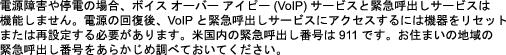
The following figure shows the front view of the supervisor engine, with the major features identified. See the corresponding callout number column in the table for a description of the feature
| Call Out |
Feature |
Description |
||
|---|---|---|---|---|
|
1 |
Model Number |
The supervior engine model number |
||
|
2 |
RESET switch (recessed) |
The RESET switch is used to reset and restart the switch.
|
||
|
3 |
UID switch and LED |
A combination push button switch and LED indicator. The blue LED can be turned on either by pressing the UID switch on the front panel or through software. The main purpose of the beacon LED is to enable identification from a remote location during configuration or troubleshooting. The ability to turn on/off the LED by pressing a switch allows you to walk to the other side of a fully populated rack and identify the switch. Pressing the blue beacon LED switch toggles the beacon LED on and off. |
||
|
4 |
USB Type A Host Port |
This USB port is a host port for an external USB disk drive. It supports USB version 2.0.
|
||
|
5 |
USB mini Type B Console Port |
This USB connector is used as a console port allowing attachment to PCs that are not equipped with an RS-232 interface. For more information about console ports, see Console Ports |
||
|
6 |
Console port (RJ-45 connector) |
This is a 10/100/1000 port that provides an RS-232 serial or console port for system management. For more information about console ports, see Console Ports |
||
|
7 |
10/100/1000 Ethernet Management Port (RJ-45 connector) |
The Ethernet management port is a Layer 3 host port to which you can connect a PC. By default, the Ethernet management port is enabled. You can use the Ethernet management port instead of the switch console port for network management. This port is not active while the switch is operating normally.
The port has a LINK LED to indicate port status. See Cisco Catalyst 4500 E-Series Supervisor Engine 9-E LEDs For more information about the management port, see Ethernet Management Port |
||
|
8 |
SECURE DIGITAL slot |
A standard Secure Data (SD) memory card interface is provided on the front panel The port has an LED that indicates if a card is inserted. See Cisco Catalyst 4500 E-Series Supervisor Engine 9-E LEDs |
||
|
9 |
1-Gigabit Ethernet (GE) or 10-GE uplink ports |
The supervisor engine has four 1-GE or 10-GE ports. These ports require either small form-factor pluggable (SFP) or SFP+ transceivers. Ports are numbered 1 to 4 and have individual uplink status LEDs. The ports also have ACTIVE LEDs that indicate the active port set. See Cisco Catalyst 4500 E-Series Supervisor Engine 9-E LEDs For more information about uplink ports, see Uplink Ports |
||
|
10 and 11 |
40-GE uplink ports |
The supervisor engine has two 40-GE ports. These ports use QSFP+ transceivers. Ports are numbered 1 and 2 and have individual LEDs that indicate uplink status. The ports also have individual ACTIVE LEDs that indicate the active port. See Cisco Catalyst 4500 E-Series Supervisor Engine 9-E LEDs For more information about uplink ports, see Uplink Ports |
For physical and environmental specifications of the Supervisor Engine 9-E, refer to data sheet at the following URL:https://www.cisco.com/c/en/us/products/collateral/switches/catalyst-4500-series-switches/nb-09-cat-4500e-sup-engine-ds-cte-en.html
Cisco Catalyst 4500 E-Series Supervisor Engine 9-E LEDs
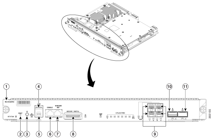
The following figure shows the front view of the supervisor engine, with the LEDs identified. See the corresponding callout number column in the table for a description of the LED.
|
Call Out |
LED |
LED Position or Color |
Meaning |
|---|---|---|---|
|
1 |
STATUS Indicates the status of the supervisor engine. |
Green |
All diagniostic tests have passed after correct image booting |
|
Orange |
System boot or a diagnostic test is in progress. This is the redundant supervisor engine (in redundant configurations). |
||
|
Red |
A diagnostic test failed. |
||
|
Off |
The supervisor engine is disabled or is not powered up. |
||
|
2 |
UID LED and switch combination |
Blue |
A combination push button switch and LED indicator. The blue LED can be turned on either by pressing the UID switch on the front panel or through software. The main purpose of the beacon LED is to enable identification from a remote location during configuration or troubleshooting. The ability to turn on/off the LED by pressing a switch allows you to walk to the other side of a fully populated rack and identify the switch. Pressing the blue beacon LED switch toggles the beacon LED on and off. |
|
3 |
DC STATUS The DC status LED indicates the current status of the wireless daughter card. |
Green |
Normal operation |
|
Blinking Green |
The daughter card is booting |
||
|
Blinking Orange |
The system is waiting for user input |
||
|
Orange |
A diagnostic test failed |
||
|
Off |
No power to the daughter card |
||
|
4 |
LINK Indicates the status of the 10/100/1000BASE-T Ethernet management port. |
Green |
The link is operational |
|
Off |
No signal is detected. |
||
|
5 |
SD Indicates the status of the secure digital port. |
Green |
SD card is inserted |
|
Off |
SD card has been removed, or the SD card is bad |
||
|
6 |
ACTIVE SUP The active supervisor engine LED indicates whether the supervisor engine is active or in standby mode in redundant supervisor engine configurations. |
Green |
Supervisor engine is active (in redundant supervisor engine configurations) |
|
Off |
Supervisor engine is in standby mode (in redundant supervisor engine configurations) |
||
|
7 |
UTILIZATION |
Green |
When the switch is operational, the eight CPU utilization LEDs indicate the current traffic load over the backplane as an approximate percentage value. Each LED lit green indicates approximately 12.5 percent of load. |
|
8 |
UPLINK ACTIVE Indicates if uplink ports 1 to 4 are active |
Green |
1-2 ACTIVE indicates ports 1 and 2 are active 3-4 ACTIVE indicates ports 3 and 4 are active |
|
Off |
Ports are not active |
||
|
9 |
UPLINK STATUS Indicates the status of uplink ports 1 to 4. |
Green |
The link is operational |
|
Orange |
The link is disabled by user |
||
|
Flashing Orange |
The power-on self-test indicates a faulty port |
||
|
Off |
No signal is detected or there is a link configuration failure |
||
|
10 |
UPLINKS ACTIVE Indicates if the QSFP+ uplink ports 1 and 2 are active |
Green |
Port is active |
|
Off |
Port is not active |
||
|
11 |
UPLINK STATUS Indicates the status of the QSFP+ uplink ports 1 and 2. |
Green |
The link is operational |
|
Orange |
The link is disabled by user |
||
|
Flashing Orange |
The power-on self-test indicates a faulty port |
||
|
Off |
No signal is detected or there is a link configuration failure |
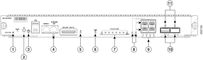
Removing and Installing the Supervisor Module
All Catalyst 4500E Series Switches support hot swapping, which lets you install, remove, replace, and rearrange supervisor engines and switching modules without powering the system off. When the system detects that a switching module has been installed or removed, it runs diagnostic and discovery routines automatically, acknowledges the presence or absence of the module, and resumes system operation with no operator intervention.
 Warning |
Only trained and qualified personnel should be allowed to install, replace, or service this equipment. Statement 1030 |
Warning |
Ultimate disposal of this product should be handled according to all national laws and regulations. Statement 1040 |
Required Tools
These tools are required to perform the installation or removal of :
-
Antistatic mat or foam pad to support the removed supervisor engine.
-
3/16-inch flat-blade screwdriver for the .
-
Your own ESD-prevention equipment or the disposable grounding wrist strap included with all upgrade kits, field-replaceable units (FRUs), and spares.
Removing the Supervisor Engine
Warning |
Hazardous voltage or energy is present on the backplane when the system is operating. Use caution when servicing. Statement 1034 |
Warning |
Invisible laser radiation may be emitted from disconnected fibers or connectors. Do not stare into beams or view directly with optical instruments. Statement 1051 |
 Caution |
To prevent ESD damage, handle supervisor engines by the carrier edges only. |
Before you begin
You will need a blank module filler plate if the module slot is to remain empty.
Procedure
| Step 1 |
Take the necessary precautions, to prevent ESD damage. Wear a grounded ESD wrist strap while handling the modules, and keep them in ESD-protective bags when they are not installed in a chassis. |
||
| Step 2 |
Disconnect any network interface cables attached to the ports on the supervisor engine that you intend to remove. |
||
| Step 3 |
If the module is equipped with removable optical transceivers, immediately install dust plugs into the transceiver’s optical bores. This prevents possible dust contamination, which can affect port performance. |
||
| Step 4 |
Loosen the two captive installation screws on either end of the supervisor engine faceplate. |
||
| Step 5 |
Grasp the left and right ejector levers at either end of the supervisor engine faceplate and simultaneously pivot the levers outward to disengage the supervisor engine from the backplane connector. |
||
| Step 6 |
Grasp the front panel of the supervisor engine with one hand and place your other hand under the carrier to support and guide it out of the slot. Do not touch the printed circuit boards or connector pins. |
||
| Step 7 |
Carefully slide the supervisor engine straight out of the slot, keeping your other hand under the carrier to guide it. |
||
| Step 8 |
Place the supervisor engine on an antistatic mat or in an antistatic bag, or immediately install the supervisor engine in another chassis slot. |
||
| Step 9 |
In a chassis configured with redundant supervisor engines, if the chassis slot is to remain empty, you must install a blank slot cover.
|
What to do next
Install the blank slot cover or a replacement supervisor engine.
Installing the Supervisor Engine
Warning |
Hazardous voltage or energy is present on the backplane when the system is operating. Use caution when servicing. Statement 1034 |
Caution |
To prevent ESD damage, handle supervisor module by the carrier edges only. |
Before you begin
-
Verify chassis compatibility and slot restrictions.
-
Catalyst 4503-E—Slot 1 only
-
Catalyst 4506-E—Slot 1 only
-
Catalyst 4507R+E—Slot 3 and slot 4 (redundant supervisor engines supported)
-
Catalyst 4510R+E—Slot 5 and slot 6 (redundant supervisor engines supported)
-
-
Verify that both the supervisor engines (in a redundant configuration) are of the same type.
Procedure
| Step 1 |
Take the necessary precautions, to prevent ESD damage. Wear a grounded ESD wrist strap while handling the modules, and keep them in ESD-protective bags when they are not installed in a chassis. |
||
| Step 2 |
Ensure that you have enough clearance to accommodate any interface equipment that you will connect directly to the supervisor module ports. |
||
| Step 3 |
Remove the existing module
|
||
| Step 4 |
Remove the new supervisor module from the shipping packaging, being careful to handle the module using only the module’s metal tray or the front panel. Do not touch the printed circuit board or the connector pins. |
||
| Step 5 |
Pivot the two module ejector levers out and away from the faceplate 
|
||
| Step 6 |
Grasp the switching module's front panel with one hand and place your other hand under the carrier to support the supervisor module. |
||
| Step 7 |
Position the new module in the slot. Make sure that you align the sides of the module carrier with the slot guides on each side of the chassis slot. |
||
| Step 8 |
Carefully slide the supervisor module into the slot. Pivot both ejector levers in simultaneously. When installed correctly
|
||
| Step 9 |
Use a screwdriver to tighten the two captive installation screws on the supervisor module. Do not over tighten the captive installation screws. |
||
| Step 10 |
Check the status of the module: |
What to do next
Install blank slot cover in empty slots, if any, to maintain consistent airflow through the switch chassis.
Module Interfaces
The supervisor module has the following interfaces or ports: USB ports, console port, management port, and uplink ports.
Warning |
To avoid electric shock, do not connect safety extra-low voltage (SELV) circuits to telephone-network voltage (TNV) circuits. LAN ports contain SELV circuits, and WAN ports contain TNV circuits. Some LAN and WAN ports both use RJ-45 connectors. Use caution when connecting cables. Statement 1021 |
Console Ports
The supervisor engine front panel provides two types of console ports:
-
USB Console Port—This is the USB mini Type B Console Port.
-
10/100/1000 or RJ45 Console Port—This console port allows you to access the switch either locally (through a console terminal) or remotely (through a modem). The console is an EIA/TIA-232 asynchronous, serial connection with hardware flow control and an RJ-45 connector.
Only one of the consoles is active at a time. When a USB host (PC) is plugged into the USB console port the hardware automatically switches over to use the USB console. Only a PC which has the necessary USB console device driver causes the USB console to become active. Plugging in a PC that does not have the USB console driver support does not cause a switchover. When the USB Cable is removed or the PC deactivates the USB connection, or a host is not detected on the USB console, the hardware automatically switches to the RJ45 console port.
The console port allows you to perform the following functions:
-
Configure the switch from the CLI
-
Monitor network statistics and errors
-
Configure SNMP agent parameters
Ethernet Management Port
The supervisor module provides a standard 10/100/1000 BASET Ethernet management port. When managing a switch, connect the PC to the Ethernet management port of a Cisco Catalyst 4500E Series switch supervisor engine.
The Ethernet management port can be used (in ROMMON mode only) to recover a switch software image that has been corrupted or destroyed due to a network catastrophe.
The specific implementation of Ethernet management port depends on the redundancy model you are applying.
The switch cannot route packets from the Ethernet management port to a network port, and from the network port to the Ethernet port. To obtain these, the Fa1 interface is automatically placed in a separate routing domain (or VRF domain), called mgmtVrf. (Observe the ip Vrf forwarding mgmtVrf line in the running configuration when you boot.)
Uplink Ports
The supervisor engine has four uplink ports that use small form-factor pluggable (SFP) transceivers or SFP+ transceivers and two uplink ports that use Quad Small Form-Factor Pluggable Plus (QSFP+) transceivers.
These ports can be used to provide additional port capacity for a fully configured switch or can reduce the need to use a chassis slot for a module. These ports use hot-swappable optical transceivers.
SFP and SFP+ Ports
Ports are numbered 1 to 4.
These ports can be configured with either SFP transceivers for 1-GE operations or SFP+ transceivers for 10-GE operations. 1 and 10-GE uplink ports operate in full-duplex mode only. Both transceivers use LC-type connectors (optical) or RJ-45 (copper). The SFP transceivers have LC connectors to interface with multimode fiber (MMF) cable and single-mode fiber (SMF) cable and RJ-45 connectors for the copper interfaces.
Each SFP module has an internal serial EEPROM that is encoded with security information. This encoding provides a way for Cisco to identify and validate that the SFP module meets the requirements for the device.
QSFP+ Ports
Ports are numbered 1 and 2.
These ports use QSFP+ transceivers for 40-GE operations. QSFP+ transceivers use LC, copper, or MPO-12 connectors.
The 40-GE QSFP+ transceiver module is a hot-swappable, parallel fiber-optical module with four independent optical transmit and receive channels. These channels terminate in a 40-GE QSFP+ transceiver.
 Note |
The QSFP+ ports do not support breakout cables. |
Installing Transceiver Modules and Cables
Use only Cisco modules on your Cisco device.
Supported Transceiver Media
For supported transceiver media types, refer to these documents on Cisco.com:
Transceiver Cabling and Installation
Each port must match the wave-length specifications on the other end of the cable, and the cable must not exceed the stipulated cable length. For cabling specifications and installation information, refer to these documents on Cisco.com:
Related Reference Installation Information
Obtaining Documentation and Submitting a Service Request
For information on obtaining documentation, submitting a service request, and gathering additional information, see the monthly What's New in Cisco Product Documentation, which also lists all new and revised Cisco technical documentation, at:
http://www.cisco.com/c/en/us/td/docs/general/whatsnew/whatsnew.html
Subscribe to the What's New in Cisco Product Documentation as a Really Simple Syndication (RSS) feed and set content to be delivered directly to your desktop using a reader application. The RSS feeds are a free service and Cisco currently supports RSS version 2.0.
 Feedback