- System Boot Verification
- Using LEDs to Identify Startup Problems
- System Messages
- Troubleshooting with Software
- Troubleshooting the Power Supply
- Troubleshooting the Fan Assembly
- Troubleshooting Backplane Modules
- Troubleshooting Switching Modules
- Troubleshooting Supervisor Engines
Troubleshooting
This chapter describes how to perform basic troubleshooting on the Catalyst 4500 E-series switch. Problems with the initial startup are often caused by a switching module that has become dislodged from the backplane or a power cord that is disconnected from the power supply.
Although temperature conditions above the maximum acceptable level rarely occur at initial startup, some environmental monitoring functions are included in this chapter because they also monitor power supply output voltages.

Note Information about troubleshooting software features and configuration problems is not discussed in this chapter.
More up to date information can be found in the release notes or Error Message Decoder tool. Information specific to your software release can be found in the software configuration guide for that release, or in the system message guide for your release. The following links may be useful in combination with this chapter:
-
Release notes
http://www.cisco.com/en/US/products/hw/switches/ps4324/prod_release_notes_list.html -
Error Message Decoder
http://www.cisco.com/cgi-bin/Support/Errordecoder/index.cgi -
Software configuration guide
http://www.cisco.com/en/US/products/hw/switches/ps4324/products_installation_and_configuration_guides_list.html -
System message guide
http://www.cisco.com/en/US/products/hw/switches/ps4324/products_system_message_guides_list.html
This chapter presented in the following sections:
- System Boot Verification
- Using LEDs to Identify Startup Problems
- System Messages
- Troubleshooting with Software
- Troubleshooting the Power Supply
- Troubleshooting the Fan Assembly
- Troubleshooting Backplane Modules
- Troubleshooting Switching Modules
- Troubleshooting Supervisor Engines
- Some Problems and Solutions
Note This chapter covers only the chassis component hardware aspects of troubleshooting. For software configuration issues, refer to the software configuration guide
http://www.cisco.com/en/US/products/hw/switches/ps4324/products_installation_and_configuration_guides_list.html
or command reference
http://www.cisco.com/en/US/products/hw/switches/ps4324/prod_command_reference_list.html
for your software release.
System Boot Verification
When the initial system boot is complete, verify the following:
Hook up a terminal and view the startup banner. Use an RJ-45-to-RJ-45 rollover cable to connect the console port to a PC with terminal emulation software set for 9600 baud, 8 data bits, no parity, and 1 stop bit. Watch for any system messages after startup.
The power supply’s LEDs should be green. Use the show environment Cisco IOS command to view power supply activity.
Listen for fan activity. The Fan tray LED should be green during operation. Use the show environment Cisco IOS command to view fan tray activity.
- That the supervisor engine and all switching modules are installed properly in their slots, and that each initialized without problems
If all of these conditions are met and the hardware installation is complete, refer to the software configuration guide and command reference publications for your switch so that you can troubleshoot the software.
If any of these conditions is not met, use the procedures in this chapter to isolate and, if possible, resolve the problem.
Using LEDs to Identify Startup Problems
The key to success when troubleshooting the system is to isolate the problem to a specific system component. Your first step is to compare what the system is doing to what it should be doing . All system states in the startup sequence are indicated by LEDs. By checking the LEDs, you can determine when and where the system failed in the startup sequence. If you have problems after the switch is on, refer to the following subsystem troubleshooting information and the configuration procedures in the software configuration guide for your switch.
After you connect the power cords to your Catalyst 4500 series switch, follow these steps to determine whether your system is operating properly:
Step 1 Check the power supply LEDs:
- The LED labeled GOOD should turn green when power is applied to the supply. The LED should remain on during normal system operation.
- If the LED labeled GOOD does not light, or if the LED labeled FAIL lights, see the “Troubleshooting the Power Supply” section.
Note If a power supply is installed and not connected to a power source, power supply LEDs indicate a failure.
Step 2 Listen for the system fan assembly. The system fan assembly should be operating whenever system power is on. If you do not hear it when the switch is on, see the “Troubleshooting the Fan Assembly” section.
Step 3 Check that the LEDs on the supervisor engine light as follows:
– It turns green when the module is operational (online).
– If the system software is unable to start up, this LED stays orange.
– If the LED labeled STATUS on the supervisor engine front panel is red or orange, connect a console to the management port and use the show environment command to check for possible problems.
- The Ethernet management port LED turns green when the module is operational (online) and a link is established with another network device. If no signal is detected, the LED labeled LINK turns off.
If there is a problem with the supervisor engine, try reseating the supervisor engine in the chassis and restarting the switch. For more troubleshooting information, see the “Troubleshooting Supervisor Engines” section.
Step 4 Verify that the LEDs labeled STATUS on each switching module are green when the supervisor engine completes initialization.
This LED indicates that the supervisor engine and switching modules are receiving power, have been recognized by the supervisor engine, and contain a valid Flash code version. However, this LED does not indicate the state of the individual interfaces on the switching modules. If an LED labeled STATUS is red or orange, try reseating the switching module or supervisor engine and restarting the switch. For more information, see the “Troubleshooting Switching Modules” section. If you determine that the switching module is not operating, contact Cisco TAC as described in the “Some Problems and Solutions” section.
Step 5 If the boot information and system banner are not displayed, verify that the terminal is set for 9600 baud, 8 data bits, no parity, and 1 stop bit and connected properly to the console port.
System Messages
System messages appear on the console if you have enabled console logging or appear in the syslog if you have enabled syslog. Many messages are for informational purposes only and do not indicate an error condition. Enter the
show logging
command to display the log messages. To better understand a specific system message, refer to the system message guide for your software release. Most messages are also documented in the Error Message Decoder tool at:
http://www.cisco.com/cgi-bin/Support/Errordecoder/index.cgi
System messages specific to the system components are mentioned in the corresponding sections that follow. If you see one of these messages, use the Decoder tool and follow the suggestion provided there.
Troubleshooting with Software
Many problems can be identified with CLI commands, and following sections will mention them as appropriate.
Certain problems can be due to not having the right software to support your hardware. For the most recent software release to get the current recommended version for a particular system component, please refer to the release notes at
http://www.cisco.com/en/US/products/hw/switches/ps4324/prod_release_notes_list.html
Troubleshooting the Power Supply
To help isolate a power subsystem problem, follow these steps:
Step 1 Check whether the power supply LED labeled GOOD is on or the LED labeled FAIL is on. (on the DC multi-input power supply, the LEDs are labeled INPUT 1, 2, or 3 or OUTPUT FAIL.)
Step 2 If the LED labeled GOOD is off or if the LED labeled FAIL is on, take the following steps:
- Ensure that the power supply is flush with the back of the chassis.
- Unplug the power cord, loosen and reinstall the power supply, tighten the captive installation screws, and then plug in the power cord.
Step 3 If the LED labeled GOOD remains off, there might be a problem with the AC source or the power cable. Connect the power cord to another power source if one is available. Verify that the source power is acceptable within the specifications of the power supply.
Step 4 If the LED labeled GOOD fails to light after you connect the power supply to a new power source, replace the power cord.
Note If this unit has more than one power cord, repeat Check whether the power supply LED labeled GOOD is on or the LED labeled FAIL is on. (on the DC multi-input power supply, the LEDs are labeled INPUT 1, 2, or 3 or OUTPUT FAIL.) through Step 4 for each power input.
Step 5 If the LED labeled GOOD still fails to light when the switch is connected to a different power source with a new power cord, the power supply is probably faulty. See the “System Messages and Power Problems” section. You may need to replace the power supply.
Step 6 If the LED labeled FAN OK fails to light when the switch is connected to a good power source with a known good power cord, there is a malfunction in the fan that cools the power supply. Replace the power supply.
Step 7 If a second power supply is available, install it in the second power supply bay.
Step 8 Check that the LED labeled GOOD is on for the additional power supply. Check that the LED labeled FAIL is off.
Step 9 If the LEDs are not on, repeat the previous procedure to troubleshoot the second power supply.
If you are unable to resolve the problem, or if you determine that either a power supply or backplane connector is faulty, contact Cisco Technical support for instructions.
System Messages and Power Problems
Check for system messages related to the power supply, and refer to the system message guide for your software release. You may need to add a power supply or upgrade to a larger one for your current configuration or verify that the switches are set properly on the power supply. Connect a terminal to the console port, and look for any of the following system messages (there may be others, depending on the software release):
C4K_IOSMODPORTMAN-4-INLINEPOWERSUPPLYBAD
C4K_IOSMODPORTMAN-4-INLINEPOWEROVERMAX
C4K_CHASSIS-2-INSUFFICIENTPOWERDETECTED
C4K_CHASSIS-2-INSUFFICIENTPOWERSHUTDOWN
C4K_CHASSIS-3-INSUFFICIENTPOWER
C4K_CHASSIS-3-INSUFFICIENTPOWERSUPPLIESDETECTED
C4K_CHASSIS-3-MIXINPOWERDETECTED
C4K_IOSMODPORTMAN-3-UNKNOWNPOWERSUPPLY
C4K_IOSMODPORTMAN-4-POWERSUPPLYBAD
C4K_IOSMODPORTMAN-4-POWERSUPPLYFANBAD
C4K_SUPERVISOR-3-POWERSUPPLYSTATUSREADFAILED
C4K_SUPERVISOR-3-POWERSUPPLYSEEPROMREADFAILED
C4K_SUPERVISOR-3-POWERSUPPLYSEEPROMINVALID
If you see any of these messages or other messages, go to the following location and enter the message text to find recommendations for your situation.
http://www.cisco.com/cgi-bin/Support/Errordecoder/index.cgi
Useful CLI Commands
You may also use the show environment status powersupply , show module all , and show power commands to monitor PS status, load, and activity.
If the show module command output shows a message that states "not enough power for module," check Appendix A, “Power Supply Specifications,” for the minimum power requirements for the power supply. There may be a problem with the power source itself.
Power Supply Mixing
The 1400 W DC multi-input supply can not be used with other power supply types, but other power supplies in this product line work with the other types during an upgrade. If you mix power supplies in a Catalyst 4500 series chassis, the switch detects the type of power supply in power supply bay 1 (PS1) and ignores the power supply in power supply bay 2 (PS2) while issuing system messages and showing the power supply in bay 2 as in the err-disable state in the output of the show power command. When the power supply in bay 1 is removed, the switch recognizes the power supply in bay 2, and you may then put a new matching power supply in bay 1. Both supplies should resume normal function.
Troubleshooting the Fan Assembly
Note All fans must be operating or a failure will occur.
Environmental problems may initially appear to be problems with the fan tray. To help isolate a fan assembly problem, follow these steps:
Step 1 Check the status LED on the fan tray.
- If the LED is off and the rest of the system is functioning, the fan tray is not getting power or is not seated correctly on the backplane.
- If the LED is green, the fans are operating normally. There may be conditions impairing fan performance, but they are minimal in impact.
- If the LED is red, one or more fans have failed.
Step 2 Connect a terminal and determine the fan tray status shown by the show environment status CLI command. The status and sensor columns should say good .
Step 3 Determine whether the airflow is restricted or if the ambient temperature in the room is too warm.
Step 4 Determine whether the power supply is functioning properly. See the “Troubleshooting the Power Supply” section.
Step 5 Verify that the fan assembly is properly seated in the backplane by loosening the captive installation screws, removing the fan assembly, and reinstalling it.
Step 7 Verify that all fans are operating. You should hear the fans at system start.
Step 8 If the system is still detecting a fan assembly failure, check for details using the CLI and contact the Cisco TAC for assistance.
System Messages and Fan Problems
Look for system messages reporting a temperature problem or problem with the fans. Individual messages may suggest different solutions. Connect a terminal to the console port, and look for any of the following system messages:
C4K_CHASSIS-2-INSUFFICIENTFANSDETECTED
C4K_CHASSIS-2-INSUFFICIENTFANSSHUTDOWN
C4K_IOSMODPORTMAN-4-CRITICALTEMP
C4K_IOSMODPORTMAN-4-FANTRAYBAD
C4K_IOSMODPORTMAN-4-FANTRAYPARTIALFAILURE
C4K_IOSMODPORTMAN-4-FANTRAYREMOVED
C4K_SUPERVISOR-3-FANTRAYREADFAILED
C4K_SUPERVISOR-3-FANTRAYSEEPROMREADFAILED
C4K_SUPERVISOR-3-FANTRAYSEEPROMINVALID
C4K_IOSMODPORTMAN-4-TEMPUNDERCRITICAL
C4K_CHASSIS-2-OVERHEATINGSHUTDOWN
If you see any of these messages or other messages related to fans, go to the following location and enter the message text to find recommendations for your situation.
http://www.cisco.com/cgi-bin/Support/Errordecoder/index.cgi
Troubleshooting Backplane Modules
The Cisco Catalyst 4500 E-series redundancy scheme uses removable redundancy modules (also called mux-buffers), on the passive backplane to switch traffic to the active supervisor engine. There is one redundancy module per switching module. Redundancy modules and a redundant clock ship standard with every Cisco Catalyst 4507R-E and 4510R-E chassis. Spare redundancy modules ( WS-X4590-E= ) and a clock module ( WS-X4K-CLOCK-E= ) are available for serviceability.
The following conditions indicate that you may need to replace the redundancy modules and clock module:
- The switch powers down and stays down for a few minutes to a few days for no clear reason.
- The output-fail LED on the power supplies are red and no power is delivered to the chassis. The other LEDs on the power supply are green.
- The Status LEDs on the switching modules and the supervisor engine are flashing green.
- CPU Utilization LEDs are flashing green or off.
If you observe these conditions, contact the Cisco TAC for assistance in ordering replacement redundancy modules and a clock.
Troubleshooting Switching Modules
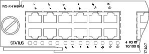
Each switching module has one LED labeled STATUS that provides information about the module and one numbered LED labeled LINK for each port on the module. Figure 5-1 shows the Gigabit Ethernet port and status LEDs. Figure 5-2 shows the 10/100BASE-T port LEDs. Table 5-1 describes the switching module LEDs and their expected behavior.
Figure 5-1 Gigabit Ethernet Port and Status LEDs
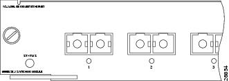
Figure 5-2 10/100BASE-T Port LEDs
Indicates the results of a series of self-tests and diagnostic tests performed by the switch. |
||
System boot, self-test diagnostics running, or the module is disabled. |
||
Port Status1 |
||
System Messages and Switching Modules
Connect a terminal to the console port, and look for any of the following system messages:
C4K_CHASSIS-3-LINECARDMUXBUFFERTOSUPALIGNMENTWRONG
C4K_CHASSIS-3-LINECARDNOTVALIDINSLOT
C4K_CHASSIS-3-MODULENOTSUPPORTHALF
C4K_IOSMODPORTMAN-4-INLINEPOWEROVERMAX
If you see any of these messages or other messages, go to the following location and enter the message text to find recommendations for your situation.
http://www.cisco.com/cgi-bin/Support/Errordecoder/index.cgi
Useful CLI Commands
Some problems can be solved by resetting the switching module. Use the hw-module module <n> reset command to reset a switching module, or remove and re-insert the switching module, which resets, restarts, and power cycles the switching module. The show module and show diagnostics online module commands can also provide information useful in solving problems with ports on individual modules.
Not all software versions support all switching modules. If you are having trouble with a module, refer to the software release notes to be sure that it is supported by your software.
Troubleshooting Supervisor Engines
This section only addresses problems with hardware. Problems with features or configuration are not covered here. Refer for your software configuration guide and release notes for information on configuring features or identifying known problems.
Table 5-2 describes the supervisor engine LEDs. Check the LEDs on your supervisor and compare them to the described LED behaviors.
The Supervisor Engine LED would turn amber or orange under the following conditions:
- Power supply failure (not the same as removal of power supply)
- Power supply fan failure
- Removal or failure of fan tray
- Mismatched power supplies in the chassis
System Messages and Supervisor Engines
Connect a terminal to the console port, and look for any of the following system messages:
C4K_CHASSIS-3-LINECARDMUXBUFFERTOSUPALIGNMENTWRONG
C4K_SUPERVISOR-3-MUXBUFFERREADSUPERVISORSELECTIONFAILED
C4K_CHASSIS-3-TEMPERATURESENSORREADFAILED
C4K_HW-3-X2IDENTIFICATIONFAILURE
C4K_HWACLMAN-4-CLASSIFCAMPARITYERROR
C4K_HWACLMAN-4-CLASSIFCAMREPLYPARITYERROR
C4K_HWACLMAN-4-CLASSIFCAMREQPARITYERROR
C4K_HWNETFLOWMAN-3-NETFLOWSTOPPED
C4K_HWNETFLOWMAN-4-FATALERRORINTERRUPTSEEN
C4K_HWNETFLOWMAN-4-NONFATALPARITYERRORINTERRUPTSEEN
C4K_IOSMODPORTMAN-4-NFLIDPROMINVALID
C4K_IOSMODPORTMAN-4-NFLMISMATCH
C4K_REDUNDANCY-2-HANDSHAKE_TIMEOUT
C4K_REDUNDANCY-2-POSTFAIL_RESET
C4K_REDUNDANCY-2-INCOMPATIBLE_SUPERVISORS
C4K_REDUNDANCY-2-IOS_VERSION_CHECK_FAIL
C4K_REDUNDANCY-2-IOS_VERSION_INCOMPATIBLE
C4K_REDUNDANCY-2-NON_SYMMETRICAL_REDUNDANT_SYSTEM
C4K_REDUNDANCY-2-POSTFAIL_RESET
C4K_REDUNDANCY-4-CONFIGSYNCFAIL
C4K_SUPERVISOR-2-SUPERVISORSEEPROMINVALID
C4K_SUPERVISOR-3-RETIMERDISABLEFAILED
C4K_SUPERVISOR-3-RETIMERINITFAILED
C4K_SUPERVISOR-3-SEEPROMREADFAILED
C4K_SUPERVISOR-4-INLINEVOLTAGEOUTOFRANGE
C4K_SUPERVISOR-7-SEEPROMWRITEFAILED
C4K_SWITCHMANAGER-3-SSOACTIVEPORTACKTIMEOUT
C4K_SYSMAN-2-POWERONSELFTESTFAIL
These system messages indicate a problem with the supervisor engine. Some problems will prevent a console connection and will not allow you to use messages in diagnosing a problem. If you are unable to establish a terminal connection and the STATUS LED is red, contact Cisco TAC immediately to order a replacement.
Problems with redundant supervisor systems are often due to mismatched active and standby supervisor engines. Redundancy requires that both supervisor engines be the same model, have the same amount of SDRAM memory and running the same Cisco IOS release. If one supervisor has a NetFlow service card, the other must as well.
Some problems with supervisor engines are due to backplane connections that are not fully seated. If removing and reinserting the supervisor engine and then restarting the switch does not solve the problem, you may need to call Cisco TAC and replace the supervisor engine.
Useful CLI Commands
Some problems can be solved by resetting the supervisor engine. Use the hw-module module <n> reset power-cycle command to reset a switching module, or remove and re-insert the switching module, which resets, restarts and power cycles the switching module. Pressing the reset button on the supervisor engine causes the software to reload, but does not power cycle the supervisor engine.
Note When you power-cycle or remove a supervisor engine in a redundant system the other supervisor engine becomes the active supervisor and the ports retain connectivity. In a non-redundant system, all of the switching modules lose connectivity until the supervisor engine is reinserted and completely restarted.
The show diagnostics power-on command may provide useful information for some supervisor engine problems.
Not all software versions support all supervisor engines. If you are having trouble with a supervisor engine, refer to the software release notes to be sure that it is supported by your software.
Standby Supervisor Engine Problems
If the standby supervisor engine module is not online or status indicates “other” or “faulty” in the output of the
show module
command or an amber status LED, create a console connection to the standby supervisor engine and verify that it is in ROMmon mode or in continuous reboot. If the standby supervisor engine is in either of these two states, refer to:
http://www.cisco.com/en/US/products/hw/switches/ps663/products_configuration_example09186a0080094ecf.shtml
Make sure that the supervisor engine module properly seats in the backplane connector and that you have completely screwed down the captive screws for the supervisor engine.
In order to determine whether the standby supervisor engine is faulty, enter the redundancy reload peer command from the active supervisor engine and through the console to the standby supervisor engine. Observe the bootup sequence in order to identify any hardware failures. Currently, the active supervisor engine cannot access the power-on diagnostics results of the standby supervisor engine.
Make sure that these configurations are synchronized between the active and redundant supervisor engines:
If a software upgrade is performed on both the active and standby supervisor engines, verify that both supervisor engines are running the same new software image. If the software images are not the same, upgrade the software image. Use the procedure in the software configuration guide for your release.
If the standby supervisor engine still does not come on line, create a service request with Cisco Technical Support. Use the log of the switch output that you collected from the previous troubleshooting steps.
Switch Self-reset
If the switch has reset or rebooted on its own, verify that the power source for the switch did not fail. If you use an uninterruptable power supply (UPS), make sure that the UPS does not have any problems.
The switch might have had a software crash. Enter the more crashinfo:data command to display the crash information including date and time of the last time that the switch crashed. To display the standby supervisor engine crash data, enter the more slavecrashinfo:data command. The crash data are not present if the switch has never crashed.
If the output indicates a software crash at the time that you suspect that the switch rebooted, the problem can be something other than a hardware failure. Contact Cisco Technical Support with the output of these commands:
If you are still unable to determine the problem, contact Cisco Technical Support.
Supervisor Ports Do Not Function
If you have dual supervisor engines in a Catalyst 4507R-E or a Catalyst 4510R-E chassis andsome uplink ports on the supervisor do not function, the system is functioning as designed, which is to have two uplinks operational at all times. The dual uplinks must also work when only one supervisor engine is present. This means that if only one supervisor engine is present and is in slot n, both ports n/1 and n/2 are functional. Also, if only one supervisor engine is present and is in slot n+1 , ports n+1/1 and N+1/2 are functional. When dual supervisor engines are present, only ports n/1 and n+1/1 are functional and n/2 andn+1/2 are not functional. For more information, refer to the redundancy chapter in the software configuration guide.
Packet Loss
If your system exhibits partial or full loss of network connectivity or packet loss, perform basic troubleshooting procedures to eliminate the common causes. The common causes include:
If you troubleshoot these common reasons and you are not able to narrow down the problem, follow the steps in this section and capture the output of commands at each step, then contact Cisco Technical Support for additional troubleshooting assistance.
Step 1 Enter the show platform software interface all command when you observe packet loss.
Step 2 Enter the show platform software interface all | include DroppedBadPackets command multiple times and look for increments in the DroppedBadPackets counter, as seen in this example:
These counters are only visible if they have a nonzero value, so if you enter the command and do not see any output, your switch does not exhibit the problem. Here is an example:
If you see increments in the TxCrcErrors or DroppedBadPackets counters, continue to Step 2.
Step 3 Enter the show platform cpu packet statistics command multiple times and look for increments in the VlanZeroBadCrc counter. Here is an example:
Step 4 If both Step 2 and Step 3 show symptoms of packet loss, enter the reload command to soft reset the switch, and observe the power-on self test (POST) results at system reset. Capture all the output as a text file.
This example shows a supervisor engine module diagnostic failure.
Step 1 If Step 4 results in a supervisor engine module diagnostic failure, pPower cycle the switch and observe the POST results at bootup.
Step 2 Enter the show diagnostics power-on command to verify the POST results from bootup and determine if diagnostics fail again. If diagnostics fail again, the problem is most likely hardware. Contact Cisco Technical Support for further assistance. If the supervisor engine passes the diagnostic tests without any failure after the power cycle in Step 4, perform these steps:
a. Collect the output from the show tech-support command.
b. Remove all power supplies from the box, and collect the serial numbers, Cisco part number, and manufacturer of the power supplies.
c. Contact Cisco Technical Support with the information that you collected.
Note If Cisco Technical Support did not assist with the troubleshoot procedure, you must provide the information in the order of these steps.
Module Not Online
Part or all of the module can fail to come online. You may have a module failure if you see a red status LED or if you see one of these statuses in the output of the show module command:
Make sure that the module is properly seated and that you have completely screwed down the module. If the module still does not come online, enter the hw-module slot slot number reset command. If the module still does not come online, try the module in a spare slot, swap the module with the slot of a module that works, or try the module in a different chassis.
If the status is “power-deny,” the switch does not have enough power available to power this module. Enter the show power command in order to confirm whether enough power is available. For more information, refer to the “Environmental Monitoring and Power Management” chapter in the software configuration guide for your software release.
If the status is “power-bad,” the switch detects a switching module but is unable to allocate power. This situation is possible if the supervisor engine cannot able to access the serial PROM (SPROM) contents on the module in order to determine the identification of the line card. Enter the show idprom module slot command to verify that the SPROM is readable. If the SPROM is not accessible, reset the module.
Enter the show diagnostics online module slot number command to identify hardware failures on the module. If the module still does not come online, create a service request with Cisco Technical Support in order to troubleshoot further. Use the log of the switch output that you collected in the above output and the troubleshooting steps that you performed.
Interface Problems
If you see an error mentioned in the output of the show interface command, the reason could be:
- A physical layer problem, such as a faulty cable or NIC
- A configuration problem, such as a speed and duplex mismatch
- A performance problem, such as an oversubscription
In order to understand and troubleshoot these problems, refer to
Troubleshooting Switch Port and Interface Problems
at:
http://www.cisco.com/en/US/products/hw/switches/ps708/products_tech_note09186a008015bfd6.shtml
Workstation Is Unable to Log In to the Network
If you observe that a workstation is unable to log into the network during startup or unable to obtain the DHCP address when you have powered up a client machine or rebooted, an initial connectivity delay that the switch introduced could be the problem. To verify this, check the following:
- Microsoft network client displays "No Domain Controllers Available".
- DHCP reports "No DHCP Servers Available."
- A Novell Internetwork Packet Exchange (IPX) network workstation does not have the Novell login screen upon bootup.
- An AppleTalk network client displays, "Access to your AppleTalk network has been interrupted. In order to reestablish your connection, open and close the AppleTalk control panel." The AppleTalk client chooser application can either fail to display a zone list or display an incomplete zone list.
- IBM Network stations can have one of these messages:
– NSB83619—Address resolution failed
– NSB83589—Failed to boot after 1 attempt
– NSB70519—Failed to connect to a server
The reason for these symptoms can be an interface delay that either Spanning Tree Protocol (STP), EtherChannel, trunking, or an autonegotiation delay causes.
NIC Compatibility Issues
You can have NIC compatibility or misconfiguration issues with the switch if you experience one of these symptoms:
- A server or client connection to the switch does not come up
- Autonegotiation issues
- Errors on the port
The reason for these symptoms can be a known NIC driver issue, speed and duplex mismatch, or autonegotiation or cabling problems. For more troubleshooting information, refer to:
http://www.cisco.com/een/US/products/hw/switches/ps708/products_tech_note09186a00800a7af0.shtm
If you still have issues after you review and follow the procedure in the document Troubleshooting Cisco Catalyst Switches to NIC Compatibility Issues , contact Cisco Technical Support for further assistance.
Interface Is in Errdisable
If the interface status is err-disable in the output of the show interface status command, some possible reasons include:
- Duplex mismatch
- Port channel misconfiguration
- Bridge protocol data unit (BPDU) guard violation
- UniDirectional Link Detection (UDLD) condition
- Late-collision detection
- Link-flap detection
- Security violation
- Port Aggregation Protocol (PAgP) flap
- Layer Two Tunneling Protocol (L2TP) guard
- DHCP snooping rate-limit
In order to troubleshoot these scenarios, refer to the specific feature information in the Catalyst 4500 Series Switch Cisco IOS Software Configuration Guide for your software release.
Faulty Supervisor Engine
If the supervisor engine STATUS LED is red, establish a console connection to the supervisor engine and enter the show diagnostics power-on command, if you can. If you are unable to get a console connection or the command output indicates a failure, contact Cisco Technical Support.
If the switch does not boot and fails self diagnostics during the boot sequence, capture the console output of the startup sequence then contact Cisco Technical Support.
If you do not see any hardware failure in the boot sequence or in the output of the show diagnostics power-on command, contact Cisco Technical Support.
Boot Problems
If the switch is in a continuous boot loop, is in ROMmon mode, or does not have a system image, there is mostly likely not a hardware problem. The supervisor engine operates in a continuous loop if you have not set the boot variable correctly and you have set the configuration register to 0x2102. For instructions on how to recover the supervisor engine, refer to the “Recovering from a Continuous Reboot” section of the document at this location:
http://www.cisco.com/en/US/products/hw/switches/ps663/products_configuration_example09186a0080094ecf.shtml
The supervisor engine goes into ROMmon mode or fails to boot when the system image is either corrupt or absent. For instructions on how to recover the supervisor engine, refer to the “Recovering from a Corrupt or Missing Image” section of the document at this location:
http://www.cisco.com/en/US/products/hw/switches/ps663/products_configuration_example09186a0080094ecf.shtml
The supervisor engines have onboard system Flash memory (bootflash), which should easily hold multiple system images. Therefore, have a backup image. In addition to the bootflash, the supervisor engine supports up to 128 MB of compact Flash in the slot0: device. The supervisor engine also provides for transfer via TFTP of the image from ROMmon mode, which enables faster recovery of absent or corrupt images.
Cannot Connect to a Switch Through the Console Port
Make sure you are using the correct type of cable. Make sure the terminal configuration matches the switch console port configuration—default console port settings are 9600 baud, 8 data bits, no parity, 1 stop bit. Make sure the cable pinouts are correct for your supervisor engine (refer to the hardware documentation for your supervisor engine).
Cannot communicate with another device, Cannot Telnet to the switch, Cannot communicate with a local or remote host
Step 1 Make sure the LINK LED for the port is green.
- Host-to-switch 10BASET connections and router-to-switch 10BASET or 100BASETX connections typically are made using a straight-through cable.
- Switch-to-switch connections typically are made using a rollover cable.
- For SC- or ST-type fiber connections, make sure transmit (Tx) on one end of the link connects to receive (Rx) on the other end of the link.
Step 3 Make sure the interface you are connecting to (sc0 or me1) is configured UP (use the show interface command to check).
Step 4 Make sure the IP address, subnet mask, and VLAN membership of the switch interface (sc0 or me1) is correct (use the show interface command).
Step 5 To prevent conflicts, make sure the me1 and sc0 interfaces are configured with IP addresses and subnet masks in different subnets (use the show interface command to check), or disable one of the interfaces using the set interface { sc0 | me1 } disable command.
Step 6 Make sure the host configuration (IP address, subnet mask, default gateway, speed, and duplex setting) is correct.
Step 7 If you cannot connect to the switch through the me1 interface, make sure the connected device is configured for half-duplex 10-Mbps operation.
Step 8 If the host is in the same subnet as the switch interface, make sure the switch interface and the switch port to which the host is connected are assigned to the same VLAN (use the show interface and show port commands to check).
Step 9 If the host is in a different subnet, make sure the default gateway (default route) on the switch is configured with the address of a router in the same subnet as the switch interface (use the show ip route command).
Step 10 Check the status of the port connection—should be “connected” (use the show port command).
Step 11 Check the spanning-tree state on the port (use the show spantree mod_num/port_num command)—if the port is in listening or learning mode, wait until the port is in forwarding mode and try to connect to the host again.
Step 12 Make sure the speed and duplex settings on the host and the appropriate switch ports are correct (use the show port command).
Step 13 If the connected device is an end station:
a. Enable spanning-tree PortFast on the port (use the set spantree portfast enable command)—PortFast places the port in forwarding mode immediately, bypassing listening and learning modes (do not use this feature for connections to non-end station devices).
b. Disable trunking on the port (use the set trunk mod_num/port_num off command).
c. Disable channeling on the port (use the set port channel port_list off command)—you must specify a valid port range with this command—you cannot specify a single port.
Step 14 Make sure the switch is learning the MAC address of the host (use the show cam dynamic command).
Step 15 If possible, try connecting to another port.
Cannot autonegotiate the port speed/duplex
Make sure autonegotiation is configured on both ends of the link (use the show port command)—you cannot configure settings manually on one end of the link and configure the other end of the link for autonegotiation. If autonegotiation fails when you connect a client NIC to the switch, check the NIC and drivers to make sure that autonegotiation is supported.
If autonegotiation is supported and properly configured but you still cannot connect, turn off autonegotiation and set the speed and duplex manually (use the set port speed and set port duplex commands).
Contacting the Cisco Technical Assistance Center
If you are unable to solve a startup problem after using the troubleshooting suggestions in this chapter, contact a Cisco TAC representative for assistance and further instructions.
Before you call, have the following information ready to help the Cisco TAC assist you as quickly as possible:
- Date you received the switch
- Chassis serial number
- Type of software and release number
- Maintenance agreement or warranty information
- Brief description of the problem
- Console captures related to your problem
- Brief explanation of the steps you have already taken to isolate and resolve the problem
See the “$paratext>” section for more information about contacting the TAC.
 Feedback