- Preface
- Using the Command-Line Interface
- Configuring Cisco IOS Configuration Engine
- Assigning the Switch IP Address and Default Gateway
- Managing Switch Stacks
- Clustering Switches
- Administering the System
- Configuring SDM Templates
- Configuring Stack Power
- Configuring Switch-Based Authentication
- Configuring IEEE 802.1x Port-Based Authentication
- Configuring MACsec Encryption
- Configuring Web-Based Authentication
- Configuring Cisco TrustSec
- Configuring Interface Characteristics
- Configuring VLANs
- Configuring VTP
- Configuring Voice VLANs
- Configuring Private VLANs
- Configuring IEEE 802.1Q and Layer 2 Protocol Tunneling
- Configuring Spanning Tree Protocol
- Configuring Multiple Spanning-Tree Protocol
- Configuring Optional Spanning-Tree Features
- Configuring Bidirection Forwarding Detection
- Configuring Resilient Ethernet Protocol
- Configuring Flex Links and the MAC Address-Table Move Update Feature
- Configuring DHCP
- Configuring IP Source Guard
- Configuring Dynamic ARP Inspection
- Configuring MLD Snooping
- Configuring the Cisco Discovery Protocol
- Configuring Port-Based Traffic Control
- Configuring LLDP, LLDP-MED, and Wired Location Service
- Configuring UniDirectional Link Detection
- Configuring SPAN and RSPAN
- Configuring RMON
- Configuring System Message Logging and Smart Logging
- Configuring Simple Network Management Protocol
- Configuring Embedded Event Manager
- Information about Network Security with ACLs
- Configuring QoS
- Configuring IPv6 ACL
- Configuring EtherChannels
- Configuring Link-State Tracking
- Configuring Telepresence E911 IP Phone Support
- Configuring IP Unicast Routing
- Configuring IPv6 Unicast Routing
- Implementing IPv6 Multicast
- Configuring HSRP and VRRP
- Configuring Service Level Agreements
- Configuring Enhanced Object Tracking
- Configuring Cache Services Using the Web Cache Communication Protocol
- Configuring MSDP
- Configuring Fallback Bridging
- Troubleshooting the Software Configuration
- Configuring Online Diagnostics
- Working with the Cisco IOS File System, Configuration Files, and Software Images
- Index
- Finding Feature Information
- Information About Configuring Interface Characteristics
- Interface Connections
- Interface Configuration Mode
- Interface Range Configuration Guidelines
- Interface Speed and Duplex Mode
- Speed and Duplex Configuration Guidelines
- IEEE 802.3x Flow Control
- Default Ethernet Interface Configuration
- Layer 3 Interfaces
- Cisco eXpandable Power System 2200
- Configuring Interfaces
- Configuring a Range of Interfaces
- Configuring and Using Interface Range Macros
- Configuring Ethernet Interfaces
- Configuring Layer 3 Interfaces
- Configuring SVI Autostate Exclude
- Configuring the Console Media Type
- Configuring the USB Inactivity Timeout
- How to Configure the XPS 2200
- Adding a Description to an Interface: Example
- Identifying Interfaces on a Stack-Capable Switch: Examples
- Configuring a Range of Interfaces: Examples
- Configuring and Using Interface Range Macros: Examples
- Setting Interface Speed and Duplex Mode: Example
- Configuring Layer 3 Interfaces: Example
- Configuring the Console Media Type: Example
- Configuring the USB Inactivity Timeout: Example
Configuring Interface Characteristics
Finding Feature Information
Your software release may not support all the features documented in this module. For the latest caveats and feature information, see Bug Search Tool and the release notes for your platform and software release. To find information about the features documented in this module, and to see a list of the releases in which each feature is supported, see the feature information table at the end of this module.
Use Cisco Feature Navigator to find information about platform support and Cisco software image support. To access Cisco Feature Navigator, go to http://www.cisco.com/go/cfn. An account on Cisco.com is not required.
Information About Configuring Interface Characteristics
- Interface Types
- Using the Switch USB Ports
- Interface Connections
- Interface Configuration Mode
- Interface Range Configuration Guidelines
- Interface Speed and Duplex Mode
- Speed and Duplex Configuration Guidelines
- IEEE 802.3x Flow Control
- Default Ethernet Interface Configuration
- Layer 3 Interfaces
- Cisco eXpandable Power System 2200
Interface Types
This section describes the different types of interfaces supported by the switch. The rest of the chapter describes configuration procedures for physical interface characteristics.
 Note | The stack ports on the rear of the stacking-capable switches are not Ethernet ports and cannot be configured. |
- Port-Based VLANs
- Switch Ports
- Routed Ports
- Switch Virtual Interfaces
- EtherChannel Port Groups
- 10-Gigabit Ethernet Interfaces
- Power over Ethernet Ports
Port-Based VLANs
A VLAN is a switched network that is logically segmented by function, team, or application, without regard to the physical location of the users. Packets received on a port are forwarded only to ports that belong to the same VLAN as the receiving port. Network devices in different VLANs cannot communicate with one another without a Layer 3 device to route traffic between the VLANs.
VLAN partitions provide hard firewalls for traffic in the VLAN, and each VLAN has its own MAC address table. A VLAN comes into existence when a local port is configured to be associated with the VLAN, when the VLAN Trunking Protocol (VTP) learns of its existence from a neighbor on a trunk, or when a user creates a VLAN. VLANs can be formed with ports across the stack.
To configure VLANs, use the vlan vlan-id global configuration command to enter VLAN configuration mode. The VLAN configurations for normal-range VLANs (VLAN IDs 1 to 1005) are saved in the VLAN database. If VTP is version 1 or 2, to configure extended-range VLANs (VLAN IDs 1006 to 4094), you must first set VTP mode to transparent. Extended-range VLANs created in transparent mode are not added to the VLAN database but are saved in the switch running configuration. With VTP version 3, you can create extended-range VLANs in client or server mode. These VLANs are saved in the VLAN database.
In a switch stack, the VLAN database is downloaded to all switches in a stack, and all switches in the stack build the same VLAN database. The running configuration and the saved configuration are the same for all switches in a stack.
Add ports to a VLAN by using the switchport interface configuration commands:
Switch Ports
Switch ports are Layer 2-only interfaces associated with a physical port. Switch ports belong to one or more VLANs. A switch port can be an access port or a trunk port. You can configure a port as an access port or trunk port or let the Dynamic Trunking Protocol (DTP) operate on a per-port basis to set the switchport mode by negotiating with the port on the other end of the link. switch ports are used for managing the physical interface and associated Layer 2 protocols and do not handle routing or bridging.
Configure switch ports by using the switchport interface configuration commands.
Access Ports
An access port belongs to and carries the traffic of only one VLAN (unless it is configured as a voice VLAN port). Traffic is received and sent in native formats with no VLAN tagging. Traffic arriving on an access port is assumed to belong to the VLAN assigned to the port. If an access port receives a tagged packet (Inter-Switch Link [ISL] or IEEE 802.1Q tagged), the packet is dropped, and the source address is not learned.
Two types of access ports are supported:
-
Static access ports are manually assigned to a VLAN (or through a RADIUS server for use with IEEE 802.1x.
-
VLAN membership of dynamic access ports is learned through incoming packets. By default, a dynamic access port is not a member of any VLAN, and forwarding to and from the port is enabled only when the VLAN membership of the port is discovered. Dynamic access ports on the switch are assigned to a VLAN by a VLAN Membership Policy Server (VMPS). The VMPS can be a Catalyst 6500 series switch; the switch cannot be a VMPS server.
You can also configure an access port with an attached Cisco IP Phone to use one VLAN for voice traffic and another VLAN for data traffic from a device attached to the phone.
Trunk Ports
A trunk port carries the traffic of multiple VLANs and by default is a member of all VLANs in the VLAN database. These trunk port types are supported:
-
In an ISL trunk port, all received packets are expected to be encapsulated with an ISL header, and all transmitted packets are sent with an ISL header. Native (non-tagged) frames received from an ISL trunk port are dropped.
-
An IEEE 802.1Q trunk port supports simultaneous tagged and untagged traffic. An IEEE 802.1Q trunk port is assigned a default port VLAN ID (PVID), and all untagged traffic travels on the port default PVID. All untagged traffic and tagged traffic with a NULL VLAN ID are assumed to belong to the port default PVID. A packet with a VLAN ID equal to the outgoing port default PVID is sent untagged. All other traffic is sent with a VLAN tag.
Although by default, a trunk port is a member of every VLAN known to the VTP, you can limit VLAN membership by configuring an allowed list of VLANs for each trunk port. The list of allowed VLANs does not affect any other port but the associated trunk port. By default, all possible VLANs (VLAN ID 1 to 4094) are in the allowed list. A trunk port can become a member of a VLAN only if VTP knows of the VLAN and if the VLAN is in the enabled state. If VTP learns of a new, enabled VLAN and the VLAN is in the allowed list for a trunk port, the trunk port automatically becomes a member of that VLAN and traffic is forwarded to and from the trunk port for that VLAN. If VTP learns of a new, enabled VLAN that is not in the allowed list for a trunk port, the port does not become a member of the VLAN, and no traffic for the VLAN is forwarded to or from the port.
Tunnel Ports
Tunnel ports are used in IEEE 802.1Q tunneling to segregate the traffic of customers in a service-provider network from other customers who are using the same VLAN number. You configure an asymmetric link from a tunnel port on a service-provider edge switch to an IEEE 802.1Q trunk port on the customer switch. Packets entering the tunnel port on the edge switch, already IEEE 802.1Q-tagged with the customer VLANs, are encapsulated with another layer of an IEEE 802.1Q tag (called the metro tag), containing a VLAN ID unique in the service-provider network, for each customer. The double-tagged packets go through the service-provider network keeping the original customer VLANs separate from those of other customers. At the outbound interface, also a tunnel port, the metro tag is removed, and the original VLAN numbers from the customer network are retrieved.
Tunnel ports cannot be trunk ports or access ports and must belong to a VLAN unique to each customer.
Routed Ports
A routed port is a physical port that acts like a port on a router; it does not have to be connected to a router. A routed port is not associated with a particular VLAN, as is an access port. A routed port behaves like a regular router interface, except that it does not support VLAN subinterfaces. Routed ports can be configured with a Layer 3 routing protocol. A routed port is a Layer 3 interface only and does not support Layer 2 protocols, such as DTP and STP.
Note | Routed ports are not supported on switches running theLAN Base image. However, with the LAN Base image, you can configure up to 16 static routes on SVIs. |
Configure routed ports by putting the interface into Layer 3 mode with the no switchport interface configuration command. Then assign an IP address to the port, enable routing, and assign routing protocol characteristics by using the ip routing and router protocol global configuration commands.
Note | Entering a no switchport interface configuration command shuts down the interface and then re-enables it, which might generate messages on the device to which the interface is connected. When you put an interface that is in Layer 2 mode into Layer 3 mode, the previous configuration information related to the affected interface might be lost. |
The number of routed ports that you can configure is not limited by software. However, the interrelationship between this number and the number of other features being configured might impact CPU performance because of hardware limitations.
Note | The IP Base image supports static routing and the Routing Information Protocol (RIP). The LAN Base image supports 16 user-configured static routes on SVIs. For full Layer 3 routing or for fallback bridging, you must enable the IP Services image on the standalone switch, or the active switch. |
Switch Virtual Interfaces
A switch virtual interface (SVI) represents a VLAN of switch ports as one interface to the routing or bridging function in the system. You can associate only one SVI with a VLAN. You configure an SVI for a VLAN only to route between VLANs or to provide IP host connectivity to the switch. By default, an SVI is created for the default VLAN (VLAN 1) to permit remote switch administration. Additional SVIs must be explicitly configured.
Note | You cannot delete interface VLAN 1. |
SVIs provide IP host connectivity only to the system. SVIs are created the first time that you enter the vlan interface configuration command for a VLAN interface. The VLAN corresponds to the VLAN tag associated with data frames on an ISL or IEEE 802.1Q encapsulated trunk or the VLAN ID configured for an access port. Configure a VLAN interface for each VLAN for which you want to route traffic, and assign it an IP address.
Although the switch stack or switch supports a total of 1005 VLANs and SVIs (255 if the switch is running the LAN Base image, the interrelationship between the number of SVIs and routed ports and the number of other features being configured might impact CPU performance because of hardware limitations.
When you create an SVI, it does not become active until it is associated with a physical port.
SVI Autostate Exclude
The line state of an SVI with multiple ports on a VLAN is in the up state when it meets these conditions:
-
The VLAN exists and is active in the VLAN database on the switch
-
The VLAN interface exists and is not administratively down.
-
At least one Layer 2 (access or trunk) port exists, has a link in the up state on this VLAN, and is in the spanning-tree forwarding state on the VLAN.
Note | The protocol link state for VLAN interfaces come up when the first switchport belonging to the corresponding VLAN link comes up and is in STP forwarding state. |
The default action, when a VLAN has multiple ports, is that the SVI goes down when all ports in the VLAN go down. You can use the SVI autostate exclude feature to configure a port so that it is not included in the SVI line-state up-or-down calculation. For example, if the only active port on the VLAN is a monitoring port, you might configure autostate exclude on that port so that the VLAN goes down when all other ports go down. When enabled on a port, autostate exclude applies to all VLANs that are enabled on that port.
The VLAN interface is brought up when one Layer 2 port in the VLAN has had time to converge (transition from STP listening-learning state to forwarding state). This prevents features such as routing protocols from using the VLAN interface as if it were fully operational and minimizes other problems, such as routing black holes.
EtherChannel Port Groups
EtherChannel port groups treat multiple switch ports as one switch port. These port groups act as a single logical port for high-bandwidth connections between switches or between switches and servers. An EtherChannel balances the traffic load across the links in the channel. If a link within the EtherChannel fails, traffic previously carried over the failed link changes to the remaining links. You can group multiple trunk ports into one logical trunk port, group multiple access ports into one logical access port, group multiple tunnel ports into one logical tunnel port, or group multiple routed ports into one logical routed port. Most protocols operate over either single ports or aggregated switch ports and do not recognize the physical ports within the port group. Exceptions are the DTP, the Cisco Discovery Protocol (CDP), and the Port Aggregation Protocol (PAgP), which operate only on physical ports.
When you configure an EtherChannel, you create a port-channel logical interface and assign an interface to the EtherChannel. For Layer 3 interfaces, you manually create the logical interface by using the interface port-channel global configuration command. Then you manually assign an interface to the EtherChannel by using the channel-group interface configuration command. For Layer 2 interfaces, use the channel-group interface configuration command to dynamically create the port-channel logical interface. This command binds the physical and logical ports together.
10-Gigabit Ethernet Interfaces
A 10-Gigabit Ethernet interface operates only in full-duplex mode. The interface can be configured as a switched or routed port.
The switch has a network module slot into which you can insert a 10-Gigabit Ethernet network module, a 1-Gigabit Ethernet network module, or a blank module.
A 10-Gigabit Ethernet interface operates only in full-duplex mode. The interface can be configured as a switched or routed port.
For more information about the Cisco TwinGig Converter Module, see the switch hardware installation guide and your transceiver module documentation.
Power over Ethernet Ports
A PoE-capable switch port automatically supplies power to one of these connected devices if the switch senses that there is no power on the circuit:
-
a Cisco pre-standard powered device (such as a Cisco IP Phone or a Cisco Aironet Access Point)
-
an IEEE 802.3af-compliant powered device
A powered device can receive redundant power when it is connected to a PoE switch port and to an AC power source. The device does not receive redundant power when it is only connected to the PoE port.
Using the Switch USB Ports
The switch has two USB ports on the front panel — a USB mini-Type B console port and a USB Type A port.
USB Mini-Type B Console Port
The switch has the following console ports:
Console output appears on devices connected to both ports, but console input is active on only one port at a time. By default, the USB connector takes precedence over the RJ-45 connector.
Note | Windows PCs require a driver for the USB port. See the hardware installation guide for driver installation instructions. |
Use the supplied USB Type A-to-USB mini-Type B cable to connect a PC or other device to the switch. The connected device must include a terminal emulation application. When the switch detects a valid USB connection to a powered-on device that supports host functionality (such as a PC), input from the RJ-45 console is immediately disabled, and input from the USB console is enabled. Removing the USB connection immediately reenables input from the RJ-45 console connection. An LED on the switch shows which console connection is in use.
Console Port Change Logs
At software startup, a log shows whether the USB or the RJ-45 console is active. Each switch in a stack issues this log. Every switch always first displays the RJ-45 media type.
In the sample output, Switch 1 has a connected USB console cable. Because the bootloader did not change to the USB console, the first log from Switch 1 shows the RJ-45 console. A short time later, the console changes and the USB console log appears. Switch 2 and Switch 3 have connected RJ-45 console cables.
switch-stack-1
*Mar  1 00:01:00.171: %USB_CONSOLE-6-MEDIA_RJ45: Console media-type is RJ45.
*Mar  1 00:01:00.431: %USB_CONSOLE-6-MEDIA_USB: Console media-type is USB.
switch-stack-2
*Mar  1 00:01:09.835: %USB_CONSOLE-6-MEDIA_RJ45: Console media-type is RJ45.

switch-stack-3
*Mar  1 00:01:10.523: %USB_CONSOLE-6-MEDIA_RJ45: Console media-type is RJ45.
When the USB cable is removed or the PC de-activates the USB connection, the hardware automatically changes to the RJ-45 console interface:
switch-stack-1
Mar  1 00:20:48.635: %USB_CONSOLE-6-MEDIA_RJ45: Console media-type is RJ45.
You can configure the console type to always be RJ-45, and you can configure an inactivity timeout for the USB connector.
USB Type A Port
The USB Type A port provides access to external USB flash devices, also known as thumb drives or USB keys. The port supports Cisco USB flash drives with capacities from 128 MB to 8 GB (USB devices with port densities of 128 MB, 256 MB, 1 GB, 4 GB, 8 GB are supported). You can use standard Cisco IOS command- line interface (CLI) commands to read, write, erase, and copy to or from the flash device. You can also configure the switch to boot from the USB flash drive.
Booting from the USB Flash Device
1.
enable
3.
boot system flash usbflash0:
image
5.
copy running-config
startup-config
DETAILED STEPS
Interface Connections
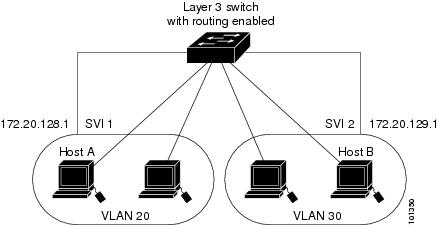
Devices within a single VLAN can communicate directly through any switch. Ports in different VLANs cannot exchange data without going through a routing device. With a standard Layer 2 switch, ports in different VLANs have to exchange information through a router. By using the switch with routing enabled, when you configure both VLAN 20 and VLAN 30 with an SVI to which an IP address is assigned, packets can be sent from Host A to Host B directly through the switch with no need for an external router.
When the IP Services image is running on the switch or the active switch, the switch uses two methods to forward traffic between interfaces: routing and fallback bridging. If the IP Base image is on the switch or the active switch, only basic routing (static routing and RIP) is supported. Whenever possible, to maintain high performance, forwarding is done by the switch hardware. However, only IPv4 packets with Ethernet II encapsulation are routed in hardware. Non-IP traffic and traffic with other encapsulation methods are fallback-bridged by hardware.
-
The routing function can be enabled on all SVIs and routed ports. The switch routes only IP traffic. When IP routing protocol parameters and address configuration are added to an SVI or routed port, any IP traffic received from these ports is routed.
-
Fallback bridging forwards traffic that the switch does not route or traffic belonging to a nonroutable protocol, such as DECnet. Fallback bridging connects multiple VLANs into one bridge domain by bridging between two or more SVIs or routed ports. When configuring fallback bridging, you assign SVIs or routed ports to bridge groups with each SVI or routed port assigned to only one bridge group. All interfaces in the same group belong to the same bridge domain.
Interface Configuration Mode
The switch supports these interface types:
-
Physical ports—switch ports and routed ports
-
VLANs—switch virtual interfaces
-
Port channels—EtherChannel interfaces
You can also configure a range of interfaces.
To configure a physical interface (port), specify the interface type, stack member number (only stacking-capable switches), module number, and switch port number, and enter interface configuration mode.
-
Type—Gigabit Ethernet (gigabitethernet or gi) for 10/100/1000 Mb/s Ethernet ports, 10-Gigabit Ethernet (tengigabitethernet or te) for 10,000 Mb/s, or small form-factor pluggable (SFP) module Gigabit Ethernet interfaces (gigabitethernet or gi).
-
Stack member number—The number that identifies the switch within the stack. The switch number range is 1 to 9 and is assigned the first time the switch initializes. The default switch number, before it is integrated into a switch stack, is 1. When a switch has been assigned a stack member number, it keeps that number until another is assigned to it.
You can use the switch port LEDs in Stack mode to identify the stack member number of a switch.
-
Module number—The module or slot number on the switch: switch (downlink) ports are 0, and uplink ports are 1.
-
Port number—The interface number on the switch. The 10/100/1000 port numbers always begin at 1, starting with the far left port when facing the front of the switch, for example, gigabitethernet1/0/1 or gigabitethernet1/0/8.
On a switch with 10/100/1000 ports and Cisco TwinGig Converter Modules in the 10-GigabitEthernet module slots, the port numbers restart with the 10-Gigabit Ethernet ports:tengigabitethernet1/0/1
On a switch with 10/100/1000 ports and Cisco dual SFP X2 converter modules in the 10-Gigabit Ethernet module slots, the SFP module ports are numbered consecutively following the 10/100/1000 interfaces. For example, if the switch has 24 10/100/1000 ports, the SFP module ports are gigabitethernet1/0/25 through gigabitethernet1/0/28.
You can identify physical interfaces by physically checking the interface location on the switch. You can also use the show privileged EXEC commands to display information about a specific interface or all the interfaces on the switch. The remainder of this chapter primarily provides physical interface configuration procedures.
These are examples of how to identify interfaces on a stacking-capable switch:
-
To configure 10/100/1000 port 4 on a standalone switch, enter this command:
Switch(config)# interface gigabitethernet1/0/4 -
To configure 10-Gigabit Ethernet port 1 on a standalone switch, enter this command:
Switch(config)# interface tengigabitethernet1/0/1 -
To configure 10-Gigabit Ethernet port on stack member 3, enter this command:
Switch(config)# interface tengigabitethernet3/0/1 -
To configure the first SFP module port on stack member 1 with 16 10/100/1000 ports, enter this command:
Switch(config)# interface gigabitethernet1/0/25
Interface Range Configuration Guidelines
When using the interface range global configuration command, note these guidelines
-
Valid entries for port-range:
- vlan vlan-ID - vlan-ID, where the VLAN ID is 1 to 4094.
-
gigabitethernet module/{first port} -{last port}, where the module is always 0.
-
gigabitethernet stack member/module{first port} -{last port}, where the module is always 0.
-
gigabitethernet module/{first port} -{last port}, where the module is always 0.
-
tengigabitethernet stack member/module{first port} -{last port}, where the module is always 0.
-
port-channelport -channel-number-port -channel-number , where the port channel number is 1 to 48.
Note
When you use the interface range command with port channels, the first and last port-channel number must be active port channels.
-
You must add a space between the first interface number and the hyphen when using the interface range command. For example, the command interface range gigabitethernet1/0/1 - 4 is a valid range; the command interface range gigabitethernet1/0/1-4 is not a valid range.
-
The interface range command only works with VLAN interfaces that have been configured with the interface vlan command. The show running-config privileged EXEC command displays the configured VLAN interfaces. VLAN interfaces not displayed by the show running-config command cannot be used with the interface range command.
-
All interfaces defined in a range must be the same type (all Gigabit Ethernet ports, all 10-Gigabit Ethernet ports, all EtherChannel ports, or all VLANs), but you can enter multiple ranges in a command.
If you enter multiple configuration commands while you are in interface-range mode, each command is executed as it is entered. The commands are not batched and executed after you exit interface-range mode. If you exit interface-range configuration mode while the commands are being executed, some commands might not be executed on all interfaces in the range. Wait until the command prompt reappears before exiting interface-range configuration mode.
Interface Speed and Duplex Mode
Ethernet interfaces on the switch operate at 10, 100, 1000, or 10,000 Mb/s and in either full- or half-duplex mode. In full-duplex mode, two stations can send and receive traffic at the same time. Normally, 10-Mb/s ports operate in half-duplex mode, which means that stations can either receive or send traffic.
Switch models include Gigabit Ethernet (10/100/1000-Mb/s) ports, 10-Gigabit Ethernet ports, and small form-factor pluggable (SFP) module slots supporting SFP modules.
Speed and Duplex Configuration Guidelines
When configuring an interface speed and duplex mode, note these guidelines:
-
The 10-Gigabit Ethernet ports do not support the speed and duplex features. These ports operate only at 10,000 Mb/s and in full-duplex mode.
-
Gigabit Ethernet (10/100/1000-Mb/s) ports support all speed options and all duplex options (auto, half, and full). However, Gigabit Ethernet ports operating at 1000 Mb/s do not support half-duplex mode.
- For SFP module ports, the speed and duplex CLI options change depending on the SFP module type:
-
If both ends of the line support autonegotiation, we highly recommend the default setting of auto negotiation.
-
If one interface supports autonegotiation and the other end does not, configure duplex and speed on both interfaces; do not use the auto setting on the supported side.
-
When STP is enabled and a port is reconfigured, the switch can take up to 30 seconds to check for loops. The port LED is amber while STP reconfigures.
 Caution | Changing the interface speed and duplex mode configuration might shut down and re-enable the interface during the reconfiguration. |
IEEE 802.3x Flow Control
Flow control enables connected Ethernet ports to control traffic rates during congestion by allowing congested nodes to pause link operation at the other end. If one port experiences congestion and cannot receive any more traffic, it notifies the other port by sending a pause frame to stop sending until the condition clears. Upon receipt of a pause frame, the sending device stops sending any data packets, which prevents any loss of data packets during the congestion period.
Note | The switch ports can receive, but not send, pause frames. |
You use the flowcontrol interface configuration command to set the interface’s ability to receive pause frames to on, off, or desired. The default state is off.
When set to desired, an interface can operate with an attached device that is required to send flow-control packets or with an attached device that is not required to but can send flow-control packets.
These rules apply to flow control settings on the device:
-
receive on (or desired): The port cannot send pause frames but can operate with an attached device that is required to or can send pause frames; the port can receive pause frames.
-
receive off: Flow control does not operate in either direction. In case of congestion, no indication is given to the link partner, and no pause frames are sent or received by either device.
Note | For details on the command settings and the resulting flow control resolution on local and remote ports, see the flowcontrol interface configuration command in the command reference for this release. |
Default Ethernet Interface Configuration
To configure Layer 2 parameters, if the interface is in Layer 3 mode, you must enter the switchport interface configuration command without any parameters to put the interface into Layer 2 mode. This shuts down the interface and then re-enables it, which might generate messages on the device to which the interface is connected. When you put an interface that is in Layer 3 mode into Layer 2 mode, the previous configuration information related to the affected interface might be lost, and the interface is returned to its default configuration.
|
Feature |
Default Setting |
||
|---|---|---|---|
|
Operating mode |
Layer 2 or switching mode (switchport command). |
||
|
Allowed VLAN range |
VLANs 1– 4094. |
||
|
Default VLAN (for access ports) |
VLAN 1 (Layer 2 interfaces only). |
||
|
Native VLAN (for IEEE 802.1Q trunks) |
VLAN 1 (Layer 2 interfaces only). |
||
|
VLAN trunking |
Switchport mode dynamic auto (supports DTP) (Layer 2 interfaces only). |
||
|
Port enable state |
All ports are enabled. |
||
|
Port description |
None defined. |
||
|
Speed |
Autonegotiate. (Not supported on the 10-Gigabit interfaces.) |
||
|
Duplex mode |
Autonegotiate. (Not supported on the 10-Gigabit interfaces.) |
||
|
Flow control |
Flow control is set to receive: off. It is always off for sent packets. |
||
|
EtherChannel (PAgP) |
Disabled on all Ethernet ports. |
||
|
Port blocking (unknown multicast and unknown unicast traffic) |
Disabled (not blocked) (Layer 2 interfaces only). |
||
|
Broadcast, multicast, and unicast storm control |
Disabled. |
||
|
Protected port |
Disabled (Layer 2 interfaces only). |
||
|
Port security |
Disabled (Layer 2 interfaces only). |
||
|
Port Fast |
Disabled. |
||
|
Auto-MDIX |
Enabled.
|
||
|
Power over Ethernet (PoE) |
Enabled (auto). |
Layer 3 Interfaces
Note | Layer 3 interfaces are not supported on switches running the LAN Base image. |
The switch supports these types of Layer 3 interfaces:
-
SVIs: You should configure SVIs for any VLANs for which you want to route traffic. SVIs are created when you enter a VLAN ID following the interface vlan global configuration command. To delete an SVI, use the no interface vlan global configuration command. You cannot delete interface VLAN 1.
Note
When you create an SVI, it does not become active until it is associated with a physical port.
When configuring SVIs, you can also configure SVI autostate exclude on a port in the SVI to exclude that port from being included in determining SVI line-state status.
-
Routed ports: Routed ports are physical ports configured to be in Layer 3 mode by using the no switchport interface configuration command.
-
Layer 3 EtherChannel ports: EtherChannel interfaces made up of routed ports.
A Layer 3 switch can have an IP address assigned to each routed port and SVI.
There is no defined limit to the number of SVIs and routed ports that can be configured in a switch or in a switch stack. However, the interrelationship between the number of SVIs and routed ports and the number of other features being configured might have an impact on CPU usage because of hardware limitations. If the switch is using its maximum hardware resources, attempts to create a routed port or SVI have these results:
-
If you try to create a new routed port, the switch generates a message that there are not enough resources to convert the interface to a routed port, and the interface remains as a switchport.
-
If you try to create an extended-range VLAN, an error message is generated, and the extended-range VLAN is rejected.
-
If the switch is notified by VLAN Trunking Protocol (VTP) of a new VLAN, it sends a message that there are not enough hardware resources available and shuts down the VLAN. The output of the show vlan user EXEC command shows the VLAN in a suspended state.
-
If the switch attempts to boot up with a configuration that has more VLANs and routed ports than hardware can support, the VLANs are created, but the routed ports are shut down, and the switch sends a message that this was due to insufficient hardware resources.
All Layer 3 interfaces require an IP address to route traffic. This procedure shows how to configure an interface as a Layer 3 interface and how to assign an IP address to an interface.
Note | If the physical port is in Layer 2 mode (the default), you must enter the no switchport interface configuration command to put the interface into Layer 3 mode. Entering a no switchport command disables and then re-enables the interface, which might generate messages on the device to which the interface is connected. Furthermore, when you put an interface that is in Layer 2 mode into Layer 3 mode, the previous configuration information related to the affected interface might be lost, and the interface is returned to its default configuration |
Cisco eXpandable Power System 2200
The Cisco eXpandable Power System (XPS) 2200 is a standalone power system that you can connect to the stacking-capable or nonstacking-capable switches. The XPS 2200 can provide backup power to connected devices that experience a power supply failure or, in power stack, it can supply additional power to the power stack budget.
The XPS 2200 power ports and internal power supplies can operate in redundant power supply (RPS) mode or stack power (SP) mode. Stack-power mode is used only on stacking-capable switches in a power stack. With no XPS, a power stack operates in ring topology with a maximum of four switches in the stack. If you merge two stacks, the total number of switches cannot exceed four. When an XPS is in the power stack, you can connect up to nine switches in the stack plus the XPS, providing power budgets to power stack members similar to stack-power ring topology operation.
All stacking-capable switches connected to an XPS on SP ports are part of the same power stack, and all power from the XPS and the switch is shared across all switches in the stack. Power sharing is the default mode, but the XPS supports the same stack power modes that are supported in a ring topology (strict and nonstrict power-sharing or redundant modes).
How to Configure Interface Characteristics
- Configuring Interfaces
- Configuring a Range of Interfaces
- Configuring and Using Interface Range Macros
- Configuring Ethernet Interfaces
- Configuring Layer 3 Interfaces
- Configuring SVI Autostate Exclude
- Configuring the Console Media Type
- Configuring the USB Inactivity Timeout
- How to Configure the XPS 2200
Configuring Interfaces
These general instructions apply to all interface configuration processes.
Configuring a Range of Interfaces
To configure multiple interfaces with the same configuration parameters, use the interface range global configuration command. When you enter the interface-range configuration mode, all command parameters that you enter are attributed to all interfaces within that range until you exit this mode.
1.
enable
2.
configure terminal
3.
interface range {port-range |
macro
macro_name}
4.
end
5.
show interfaces [interface-id]
6.
copy running-config
startup-config
DETAILED STEPS
| Command or Action | Purpose | |||
|---|---|---|---|---|
| Step 1 |
enable
Example:
Switch> enable
|
Enables privileged EXEC mode. Enter your password if prompted. | ||
| Step 2 | configure terminal
Example:
Switch# configure terminal
|
Enters global configuration mode. | ||
| Step 3 | interface range {port-range |
macro
macro_name}
Example:
Switch(config)# interface range macro
|
Specifies the range of interfaces (VLANs or physical ports) to be configured, and enter interface-range configuration mode.
| ||
| Step 4 | end
Example:
Switch(config)# end
|
Returns to privileged EXEC mode. | ||
| Step 5 | show interfaces [interface-id]
Example:
Switch# show interfaces
|
Verifies the configuration of the interfaces in the range. | ||
| Step 6 | copy running-config
startup-config
Example:
Switch# copy running-config startup-config
|
(Optional) Saves your entries in the configuration file. |
Configuring and Using Interface Range Macros
You can create an interface range macro to automatically select a range of interfaces for configuration. Before you can use the macro keyword in the interface range macro global configuration command string, you must use the define interface-range global configuration command to define the macro.
1.
enable
2.
configure terminal
3.
define interface-range
macro_name
interface-range
4.
interface range macro
macro_name
5.
end
6.
show running-config
|
include
define
7.
copy running-config
startup-config
DETAILED STEPS
| Command or Action | Purpose | |||
|---|---|---|---|---|
| Step 1 |
enable
Example:
Switch> enable
|
Enables privileged EXEC mode. Enter your password if prompted. | ||
| Step 2 | configure terminal
Example:
Switch# configure terminal
|
Enters global configuration mode. | ||
| Step 3 | define interface-range
macro_name
interface-range
Example:
Switch(config)# define interface-range enet_list gigabitethernet1/0/1 - 2
|
Defines the interface-range macro, and save it in NVRAM.
| ||
| Step 4 | interface range macro
macro_name
Example:
Switch(config)# interface range macro enet_list
|
Selects the interface range to be configured using the values saved in the interface-range macro called macro_name. You can now use the normal configuration commands to apply the configuration to all interfaces in the defined macro. | ||
| Step 5 | end
Example:
Switch(config)# end
|
Returns to privileged EXEC mode. | ||
| Step 6 | show running-config
|
include
define
Example:
Switch# show running-config | include define
|
Shows the defined interface range macro configuration. | ||
| Step 7 | copy running-config
startup-config
Example:
Switch# copy running-config startup-config
|
(Optional) Saves your entries in the configuration file. |
Configuring Ethernet Interfaces
- Setting the Interface Speed and Duplex Parameters
- Configuring IEEE 802.3x Flow Control
- Adding a Description for an Interface
Setting the Interface Speed and Duplex Parameters
1.
enable
2.
configure terminal
3.
interface
interface-id
4.
speed {10 |
100 |
1000 |
auto
[10 |
100 |
1000]
|
nonegotiate}
5.
duplex {auto |
full |
half}
6.
end
7.
show interfaces
interface-id
8.
copy
running-config
startup-config
9.
copy running-config
startup-config
DETAILED STEPS
| Command or Action | Purpose | |
|---|---|---|
| Step 1 |
enable
Example:
Switch> enable
|
Enables privileged EXEC mode. Enter your password if prompted. |
| Step 2 | configure terminal
Example:
Switch# configure terminal
|
Enters global configuration mode. |
| Step 3 | interface
interface-id
Example:
Switch(config)# interface gigabitethernet1/0/3
|
Specifies the physical interface to be configured, and enter interface configuration mode. |
| Step 4 | speed {10 |
100 |
1000 |
auto
[10 |
100 |
1000]
|
nonegotiate}
Example:
Switch(config-if)# speed 10
|
This command is not available on a 10-Gigabit Ethernet interface. Enter the appropriate speed parameter for the interface:
|
| Step 5 | duplex {auto |
full |
half}
Example:
Switch(config-if)# duplex half
|
This command is not available on a 10-Gigabit Ethernet interface. Enter the duplex parameter for the interface. Enable half-duplex mode (for interfaces operating only at 10 or 100 Mb/s). You cannot configure half-duplex mode for interfaces operating at 1000 Mb/s. You can configure the duplex setting when the speed is set to auto. |
| Step 6 | end
Example:
Switch(config-if)# end
|
Returns to privileged EXEC mode. |
| Step 7 | show interfaces
interface-id
Example:
Switch# show interfaces gigabitethernet1/0/3
|
Displays the interface speed and duplex mode configuration. |
| Step 8 | copy
running-config
startup-config
Example:
Switch# copy running-config startup-config
|
(Optional) Saves your entries in the configuration file. |
| Step 9 | copy running-config
startup-config
Example:
Switch# copy running-config startup-config
|
(Optional) Saves your entries in the configuration file. |
Configuring IEEE 802.3x Flow Control
1.
configure terminal
2.
interface
interface-id
3.
flowcontrol {receive} {on |
off |
desired}
4.
end
5.
show interfaces
interface-id
6.
copy running-config
startup-config
DETAILED STEPS
| Command or Action | Purpose | |
|---|---|---|
| Step 1 | configure terminal
Example:
Switch# configure terminal
|
Enters global configuration mode |
| Step 2 | interface
interface-id
Example:
Switch(config)# interface gigabitethernet1/0/1
|
Specifies the physical interface to be configured, and enter interface configuration mode. |
| Step 3 | flowcontrol {receive} {on |
off |
desired}
Example:
Switch(config-if)# flowcontrol receive on
|
Configures the flow control mode for the port. |
| Step 4 | end
Example:
Switch(config-if)# end
|
Returns to privileged EXEC mode. |
| Step 5 | show interfaces
interface-id
Example:
Switch# show interfaces gigabitethernet1/0/1
|
Verifies the interface flow control settings. |
| Step 6 | copy running-config
startup-config
Example:
Switch# copy running-config startup-config
|
(Optional) Saves your entries in the configuration file. |
Adding a Description for an Interface
1.
enable
2.
configure terminal
3.
interface
interface-id
4.
description
string
5.
end
6.
show interfaces
interface-id
description
7.
copy running-config
startup-config
DETAILED STEPS
| Command or Action | Purpose | |
|---|---|---|
| Step 1 |
enable
Example:
Switch> enable
|
Enables privileged EXEC mode. Enter your password if prompted. |
| Step 2 | configure terminal
Example:
Switch# configure terminal
|
Enters global configuration mode. |
| Step 3 | interface
interface-id
Example:
Switch(config)# interface gigabitethernet1/0/2
|
Specifies the interface for which you are adding a description, and enter interface configuration mode. |
| Step 4 | description
string
Example:
Switch(config-if)# description Connects to Marketing
|
Adds a description (up to 240 characters) for an interface. |
| Step 5 | end
Example:
Switch(config-if)# end
|
Returns to privileged EXEC mode. |
| Step 6 | show interfaces
interface-id
description
|
Verifies your entry. |
| Step 7 | copy running-config
startup-config
Example:
Switch# copy running-config startup-config
|
(Optional) Saves your entries in the configuration file. |
Configuring Layer 3 Interfaces
1.
enable
2.
configure terminal
3.
interface {gigabitethernet
interface-id} | {vlan
vlan-id} | {port-channel
port-channel-number}
4.
no switchport
5.
ip address
ip_address
subnet_mask
6.
no shutdown
7.
end
8.
show interfaces [interface-id]
9.
copy running-config
startup-config
DETAILED STEPS
| Command or Action | Purpose | |
|---|---|---|
| Step 1 |
enable
Example:
Switch> enable
|
Enables privileged EXEC mode. Enter your password if prompted. |
| Step 2 | configure terminal
Example:
Switch# configure terminal
|
Enters global configuration mode. |
| Step 3 | interface {gigabitethernet
interface-id} | {vlan
vlan-id} | {port-channel
port-channel-number}
Example:
Switch(config)# interface gigabitethernet1/0/2
|
Specifies the interface to be configured as a Layer 3 interface, and enter interface configuration mode. |
| Step 4 | no switchport
Example:
Switch(config-if)# no switchport
|
For physical ports only, enters Layer 3 mode. |
| Step 5 | ip address
ip_address
subnet_mask
Example:
Switch(config-if)# ip address 192.20.135.21 255.255.255.0
|
Configures the IP address and IP subnet. |
| Step 6 | no shutdown
Example:
Switch(config-if)# no shutdown
|
Enables the interface. |
| Step 7 | end
Example:
Switch(config-if)# end
|
Returns to privileged EXEC mode. |
| Step 8 | show interfaces [interface-id]
|
Verifies the configuration. |
| Step 9 | copy running-config
startup-config
Example:
Switch# copy running-config startup-config
|
(Optional) Saves your entries in the configuration file. |
Configuring SVI Autostate Exclude
1.
enable
2.
configure terminal
3.
interface
interface-id
4.
switchport autostate exclude
5.
end
6.
show running config interface
interface-id
7.
copy running-config
startup-config
DETAILED STEPS
| Command or Action | Purpose | |
|---|---|---|
| Step 1 |
enable
Example:
Switch> enable
|
Enables privileged EXEC mode. Enter your password if prompted. |
| Step 2 | configure terminal
Example:
Switch# configure terminal
|
Enters global configuration mode. |
| Step 3 | interface
interface-id
Example:
Switch(config)# interface gigabitethernet1/0/2
|
Specifies a Layer 2 interface (physical port or port channel), and enter interface configuration mode. |
| Step 4 | switchport autostate exclude
Example:
Switch(config-if)# switchport autostate exclude
|
Excludes the access or trunk port when defining the status of an SVI line state (up or down) |
| Step 5 | end
Example:
Switch(config-if)# end
|
Returns to privileged EXEC mode. |
| Step 6 | show running config interface
interface-id
|
(Optional) Shows the running configuration. Verifies the configuration. |
| Step 7 | copy running-config
startup-config
Example:
Switch# copy running-config startup-config
|
(Optional) Saves your entries in the configuration file. |
Configuring the Console Media Type
Follow these steps to set the console media type to RJ-45. If you configure the console as RJ-45, USB console operation is disabled, and input comes only through the RJ-45 connector.
This configuration applies to all switches in a stack.
1.
enable
3.
line
console 0
4.
media-type
rj45
6.
copy running-config
startup-config
DETAILED STEPS
| Command or Action | Purpose | |
|---|---|---|
| Step 1 |
enable
Example:
Switch> enable
|
Enables privileged EXEC mode. Enter your password if prompted. |
| Step 2 | configure
terminal
Example: Switch# configure terminal | |
| Step 3 | line
console 0
Example:
Switch(config)# line console 0
|
Configures the console and enters line configuration mode. |
| Step 4 | media-type
rj45
Example:
Switch(config-line)# media-type rj45
|
Configures the console media type to be only RJ-45 port. If you do not enter this command and both types are connected, the USB port is used by default. |
| Step 5 | end
Example: Switch(config)# end | |
| Step 6 | copy running-config
startup-config
Example:
Switch# copy running-config startup-config
|
(Optional) Saves your entries in the configuration file. |
Configuring the USB Inactivity Timeout
The configurable inactivity timeout reactivates the RJ-45 console port if the USB console port is activated but no input activity occurs on it for a specified time period. When the USB console port is deactivated due to a timeout, you can restore its operation by disconnecting and reconnecting the USB cable.
Note | The configured inactivity timeout applies to all switches in a stack. However, a timeout on one switch does not cause a timeout on other switches in the stack. |
1.
enable
3.
line
console 0
4.
usb-inactivity-timeout
timeout-minutes
5.
copy running-config
startup-config
DETAILED STEPS
| Command or Action | Purpose | |
|---|---|---|
| Step 1 |
enable
Example:
Switch> enable
|
Enables privileged EXEC mode. Enter your password if prompted. |
| Step 2 | configure
terminal
Example: Switch# configure terminal | |
| Step 3 | line
console 0
Example:
Switch(config)# line console 0
|
Configures the console and enters line configuration mode. |
| Step 4 | usb-inactivity-timeout
timeout-minutes
Example:
Switch(config-line)# usb-inactivity-timeout 30
|
Specify an inactivity timeout for the console port. The range is 1 to 240 minutes. The default is to have no timeout configured. |
| Step 5 | copy running-config
startup-config
Example:
Switch# copy running-config startup-config
|
(Optional) Saves your entries in the configuration file. |
How to Configure the XPS 2200
You can configure the XPS from any switch connected to an XPS port. If you enter XPS configuration commands on more than one switch, the last configuration applied takes effect. Only the switch and port name are saved in the switch configuration file.
Configuring System Names
1.
enable
3.
power xps
switch-number
name
{name |
serialnumber}
4.
power xps
switch-number
port
{name |
hostname |
serialnumber}
6.
show env xps system
7.
copy running-config
startup-config
DETAILED STEPS
| Command or Action | Purpose | |||
|---|---|---|---|---|
| Step 1 |
enable
Example:
Switch> enable
|
Enables privileged EXEC mode. Enter your password if prompted. | ||
| Step 2 | configure
terminal
| |||
| Step 3 | power xps
switch-number
name
{name |
serialnumber}
|
Configures a name for the XPS 2200 system. | ||
| Step 4 | power xps
switch-number
port
{name |
hostname |
serialnumber}
|
Configures a name for an XPS 2200 port connected to the switch. | ||
| Step 5 | end
| |||
| Step 6 | show env xps system
|
Verifies the configured name of the system and ports. | ||
| Step 7 | copy running-config
startup-config
Example:
Switch# copy running-config startup-config
|
(Optional) Saves your entries in the configuration file. |
Configuring XPS Ports
1.
enable
2.
power
xps
switch-number
port
{number |
connected}
mode
{disable |
enable}
3.
power xps
switch-number
port
{number |
connected}
role
{auto |
rps}
4.
power xps
switch-number
port
{number |
connected}
priority
port-priority
5.
show env xps port
DETAILED STEPS
| Command or Action | Purpose | |||||
|---|---|---|---|---|---|---|
| Step 1 |
enable
Example:
Switch> enable
|
Enables privileged EXEC mode. Enter your password if prompted. | ||||
| Step 2 |
power
xps
switch-number
port
{number |
connected}
mode
{disable |
enable}
|
| ||||
| Step 3 | power xps
switch-number
port
{number |
connected}
role
{auto |
rps}
|
| ||||
| Step 4 | power xps
switch-number
port
{number |
connected}
priority
port-priority
Example:
Switch
|
Sets the RPS priority of the port, where higher priority ports take precedence over low priority ports if multiple power supplies fail. This command takes effect only when the port mode is RPS. When the port mode is stack power, you set priority by using the stack power commands. | ||||
| Step 5 | show env xps port
|
Verifies the XPS configuration of the port. |
Configuring XPS Power Supplies
1.
enable
2.
power
xps
switch-number
supply
{A |
B}
mode
{rps |
sp}
3.
power xps
switch-number
supply
{A |
B}
{on |
off}
5.
show env xps power
DETAILED STEPS
| Command or Action | Purpose | |||
|---|---|---|---|---|
| Step 1 |
enable
Example:
Switch> enable
|
Enables privileged EXEC mode. Enter your password if prompted. | ||
| Step 2 |
power
xps
switch-number
supply
{A |
B}
mode
{rps |
sp}
|
Sets the XPS power supply mode.
| ||
| Step 3 | power xps
switch-number
supply
{A |
B}
{on |
off}
|
Sets the XPS power supply to be on or off. The default is for both power supplies to be on. | ||
| Step 4 | end
| |||
| Step 5 | show env xps power
|
Displays the status of the XPS power supplies. |
Monitoring Interface Characteristics
- Monitoring Interface Status
- Clearing and Resetting Interfaces and Counters
- Shutting Down and Restarting the Interface
Monitoring Interface Status
Commands entered at the privileged EXEC prompt display information about the interface, including the versions of the software and the hardware, the configuration, and statistics about the interfaces.
|
Command |
Purpose |
|---|---|
|
show env power switchswitch-number |
(Optional) Displays the status of the internal power supplies for each switch in the stack or for the specified switch. The range is 1 to 9, depending on the switch member numbers in the stack. |
|
show env rps |
Displays whether a redundant power system (RPS) is connected to the switch. |
|
show env rps detail |
(Optional) Displays the details about the RPSs that are connected to the switch or switch stack. |
|
show env rps switchswitch-number |
(Optional) Displays the RPSs that are connected to each switch in the stack or to the specified switch. The range is 1 to 9, depending on the switch member numbers in the stack. |
|
show interfaces interface-id status [err-disabled] |
Displays interface status or a list of interfaces in the error-disabled state. |
|
show interfaces [interface-id] switchport |
Displays administrative and operational status of switching (nonrouting) ports. You can use this command to find out if a port is in routing or in switching mode. |
|
show interfaces [interface-id] description |
Displays the description configured on an interface or all interfaces and the interface status. |
|
show ip interface [interface-id] |
Displays the usability status of all interfaces configured for IP routing or the specified interface. |
|
show interface [interface-id] stats |
Displays the input and output packets by the switching path for the interface. |
|
show interfaces interface-id |
(Optional) Displays speed and duplex on the interface. |
|
show interfaces transceiver dom-supported-list |
(Optional) Displays Digital Optical Monitoring (DOM) status on the connect SFP modules. |
|
show interfaces transceiver properties |
(Optional) Displays temperature, voltage, or amount of current on the interface. |
|
show interfaces [interface-id] [{transceiver properties | detail}] module number] |
Displays physical and operational status about an SFP module. |
|
show running-config interface [interface-id] |
Displays the running configuration in RAM for the interface. |
|
show version |
Displays the hardware configuration, software version, the names and sources of configuration files, and the boot images. |
|
show controllers ethernet-controller interface-id phy |
Displays the operational state of the auto-MDIX feature on the interface. |
|
show power inline interface-id |moduleswitch-number |
Displays PoE status for a switch or switch stack, for an interface, or for a specific switch in the stack. |
|
show power inline consumption |
Displays power consumption data. |
|
show power inline police |
Displays power policing data. |
Clearing and Resetting Interfaces and Counters
|
Command |
Purpose |
|---|---|
|
clear counters [interface-id] |
Clears interface counters. |
|
clear interface interface-id |
Resets the hardware logic on an interface. |
|
clear line [number | console 0 | vty number] |
Resets the hardware logic on an asynchronous serial line. |
Note | The clear counters privileged EXEC command does not clear counters retrieved by using Simple Network Management Protocol (SNMP), but only those seen with the show interface privileged EXEC command. |
Shutting Down and Restarting the Interface
Shutting down an interface disables all functions on the specified interface and marks the interface as unavailable on all monitoring command displays. This information is communicated to other network servers through all dynamic routing protocols. The interface is not mentioned in any routing updates.
1.
enable
2.
configure terminal
3.
interface {vlan
vlan-id} | {
gigabitethernetinterface-id} | {port-channel
port-channel-number}
4.
shutdown
5.
no shutdown
6.
end
DETAILED STEPS
| Command or Action | Purpose | |
|---|---|---|
| Step 1 |
enable
Example:
Switch> enable
|
Enables privileged EXEC mode. Enter your password if prompted. |
| Step 2 | configure terminal
Example:
Switch# configure terminal
|
Enters global configuration mode. |
| Step 3 | interface {vlan
vlan-id} | {
gigabitethernetinterface-id} | {port-channel
port-channel-number}
Example:
Switch(config)# interface gigabitethernet1/0/2
|
Selects the interface to be configured. |
| Step 4 | shutdown
Example:
Switch(config-if)# shutdown
|
Shuts down an interface. |
| Step 5 | no shutdown
Example:
Switch(config-if)# no shutdown
|
Restarts an interface. |
| Step 6 | end
Example:
Switch(config-if)# end
|
Returns to privileged EXEC mode. |
| Step 7 | show running-config
Example: Switch# show running-config |
Configuration Examples for Interface Characteristics
- Adding a Description to an Interface: Example
- Identifying Interfaces on a Stack-Capable Switch: Examples
- Configuring a Range of Interfaces: Examples
- Configuring and Using Interface Range Macros: Examples
- Setting Interface Speed and Duplex Mode: Example
- Configuring Layer 3 Interfaces: Example
- Configuring the Console Media Type: Example
- Configuring the USB Inactivity Timeout: Example
Adding a Description to an Interface: Example
Switch# configure terminal
Enter configuration commands, one per line. End with CNTRL/Z.
Switch(config)# interface gigabitethernet1/0/2
Switch(config-if)# description Connects to Marketing
Switch(config-if)# end
Switch# show interfaces gigabitethernet1/0/2 description
Interface Status         Protocol Description
Gi1/0/2   admin down     down     Connects to Marketing
Identifying Interfaces on a Stack-Capable Switch: Examples
To configure 10/100/1000 port 4 on a standalone switch, enter this command:
Switch(config)# interface gigabitethernet1/0/4
Configuring a Range of Interfaces: Examples
This example shows how to use the interface range global configuration command to set the speed to 100 Mb/s on ports 1 to 4 on switch 1:
Switch# configure terminal
Switch(config)# interface range gigabitethernet1/0/1 - 4
Switch(config-if-range)# speed 100
This example shows how to use a comma to add different interface type strings to the range to enable Gigabit Ethernet ports 1 to 3 and 10-Gigabit Ethernet ports 1 and 2 to receive flow-control pause frames:
Switch# configure terminal
Switch(config)# interface range gigabitethernet1/0/1 - 3 , tengigabitethernet1/0/1 - 2
Switch(config-if-range)# flowcontrol receive on
If you enter multiple configuration commands while you are in interface-range mode, each command is executed as it is entered. The commands are not batched and executed after you exit interface-range mode. If you exit interface-range configuration mode while the commands are being executed, some commands might not be executed on all interfaces in the range. Wait until the command prompt reappears before exiting interface-range configuration mode.
Configuring and Using Interface Range Macros: Examples
This example shows how to define an interface-range named enet_list to include ports 1 and 2 on switch 1 and to verify the macro configuration:
Switch# configure terminal
Switch(config)# define interface-range enet_list gigabitethernet1/0/1 - 2
Switch(config)# end
Switch# show running-config | include define
define interface-range enet_list GigabitEthernet1/0/1 - 2
This example shows how to create a multiple-interface macro named macro1:
Switch# configure terminal
Switch(config)# define interface-range macro1 gigabitethernet1/0/1 - 2, gigabitethernet1/0/5 - 7, tengigabitethernet1/0/1 -2
Switch(config)# end
This example shows how to enter interface-range configuration mode for the interface-range macro enet_list:
Switch# configure terminal
Switch(config)# interface range macro enet_list
Switch(config-if-range)#
This example shows how to delete the interface-range macro enet_list and to verify that it was deleted.
Switch# configure terminal
Switch(config)# no define interface-range enet_list
Switch(config)# end
Switch# show run | include define
Switch#
Setting Interface Speed and Duplex Mode: Example
This example shows how to set the interface speed to 100 Mb/s and the duplex mode to half on a 10/100/1000 Mb/s port:
Switch# configure terminal
Switch(config)# interface gigabitethernet1/0/3
Switch(config-if)# speed 10
Switch(config-if)# duplex half
This example shows how to set the interface speed to 100 Mb/s on a 10/100/1000 Mb/s port:
Switch# configure terminal
Switch(config)# interface gigabitethernet1/0/2
Switch(config-if)# speed 100
Configuring Layer 3 Interfaces: Example
Switch# configure terminal
Enter configuration commands, one per line.  End with CNTL/Z.
Switch(config)# interface gigabitethernet1/0/2
Switch(config-if)# no switchport
Switch(config-if)# ip address 192.20.135.21 255.255.255.0
Switch(config-if)# no shutdown
Configuring the Console Media Type: Example
This example disables the USB console media type and enables the RJ-45 console media type.
Switch# configure terminal
Switch(config)# line console 0
Switch(config-line)# media-type rj45
This configuration terminates any active USB console media type in the stack. A log shows that this termination has occurred. This example shows that the console on switch 1 reverted to RJ-45.
*Mar 1 00:25:36.860: %USB_CONSOLE-6-CONFIG_DISABLE: Console media-type USB disabled by system configuration, media-type reverted to RJ45.
At this point no switches in the stack allow a USB console to have input. A log entry shows when a console cable is attached. If a USB console cable is connected to switch 2, it is prevented from providing input.
*Mar 1 00:34:27.498: %USB_CONSOLE-6-CONFIG_DISALLOW: Console media-type USB is disallowed by system configuration, media-type remains RJ45. (switch-stk-2)
This example reverses the previous configuration and immediately activates any USB console that is connected.
Switch# configure terminal
Switch(config)# line console 0
Switch(config-line)# no media-type rj45
Configuring the USB Inactivity Timeout: Example
This example configures the inactivity timeout to 30 minutes:
Switch# configure terminal
Switch(config)# line console 0
Switch(config-line)# usb-inactivity-timeout 30
To disable the configuration, use these commands:
Switch# configure terminal
Switch(config)# line console 0
Switch(config-line)# no usb-inactivity-timeout
If there is no (input) activity on a USB console port for the configured number of minutes, the inactivity timeout setting applies to the RJ-45 port, and a log shows this occurrence:
*Mar 1 00:47:25.625: %USB_CONSOLE-6-INACTIVITY_DISABLE: Console media-type USB disabled due to inactivity, media-type reverted to RJ45.
At this point, the only way to reactivate the USB console port is to disconnect and reconnect the cable.
When the USB cable on the switch has been disconnected and reconnected, a log similar to this appears:
*Mar 1 00:48:28.640: %USB_CONSOLE-6-MEDIA_USB: Console media-type is USB.
Additional References
Error Message Decoder
| Description | Link |
|---|---|
|
To help you research and resolve system error messages in this release, use the Error Message Decoder tool. |
https://www.cisco.com/cgi-bin/Support/Errordecoder/index.cgi |
MIBs
| MIB | MIBs Link |
|---|---|
|
All supported MIBs for this release. |
To locate and download MIBs for selected platforms, Cisco IOS releases, and feature sets, use Cisco MIB Locator found at the following URL: |
Technical Assistance
| Description | Link |
|---|---|
|
The Cisco Support website provides extensive online resources, including documentation and tools for troubleshooting and resolving technical issues with Cisco products and technologies. To receive security and technical information about your products, you can subscribe to various services, such as the Product Alert Tool (accessed from Field Notices), the Cisco Technical Services Newsletter, and Really Simple Syndication (RSS) Feeds. Access to most tools on the Cisco Support website requires a Cisco.com user ID and password. |
Finding Feature Information
Your software release may not support all the features documented in this module. For the latest caveats and feature information, see Bug Search Tool and the release notes for your platform and software release. To find information about the features documented in this module, and to see a list of the releases in which each feature is supported, see the feature information table at the end of this module.
Use Cisco Feature Navigator to find information about platform support and Cisco software image support. To access Cisco Feature Navigator, go to http://www.cisco.com/go/cfn. An account on Cisco.com is not required.
Prerequisites for Ethernet Management Ports
When connecting a PC to the Ethernet management port, you must first assign an IP address.
Information about the Ethernet Management Port
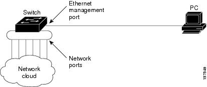
The Ethernet management port, also referred to as the Fa0 or fastethernet0 port, is a Layer 3 host port to which you can connect a PC. You can use the Ethernet management port instead of the switch console port for network management. When managing a switch stack, connect the PC to the Ethernet management port on a stack member.
- Ethernet Management Port Direct Connection to a Switch
- Ethernet Management Port Connection to Stack Switches using a Hub
- Ethernet Management Port and Routing
- Supported Features on the Ethernet Management Port
Ethernet Management Port Direct Connection to a Switch
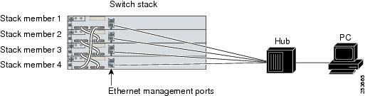
Ethernet Management Port Connection to Stack Switches using a Hub
In a stack with only stack switches, all the Ethernet management ports on the stack members are connected to a hub to which the PC is connected. The active link is from the Ethernet management port on the through the hub, to the PC. If the activeswitch fails and a new active switch is elected, the active link is now from the Ethernet management port on the new active switch to the PC.
In a mixed stack, the stack members are connected to the PC through the Ethernet management ports. The active link is from the active switch to the PC. If the active switch fails and the elected active switch is not switch 2, the active link can be from a stack member to the PC.
Ethernet Management Port and Routing
By default, the Ethernet management port is enabled. The switch cannot route packets from the Ethernet management port to a network port, and the reverse. Even though the Ethernet management port does not support routing, you may need to enable routing protocols on the port.
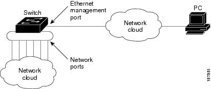
In the above figure , if the Ethernet management port and the network ports are associated with the same routing process, the routes are propagated as follows:
-
The routes from the Ethernet management port are propagated through the network ports to the network.
-
The routes from the network ports are propagated through the Ethernet management port to the network.
Because routing is not supported between the Ethernet management port and the network ports, traffic between these ports cannot be sent or received. If this happens, data packet loops occur between the ports, which disrupt the switch and network operation. To prevent the loops, configure route filters to avoid routes between the Ethernet management port and the network ports.
Supported Features on the Ethernet Management Port
The Ethernet management port supports these features:
-
Express Setup (only in switch stacks)
-
Network Assistant
-
Telnet with passwords
-
TFTP
-
Secure Shell (SSH)
-
DHCP-based autoconfiguration
-
SMNP (only the ENTITY-MIB and the IF-MIB)
-
IP ping
- Interface features
-
Cisco Discovery Protocol (CDP)
-
DHCP relay agent
-
IPv4 and IPv6 access control lists (ACLs)
-
Routing protocols
Caution | Before enabling a feature on the Ethernet management port, make sure that the feature is supported. If you try to configure an unsupported feature on the Ethernet Management port, the feature might not work properly, and the switch might fail. |
How to Configure the Ethernet Management Port
Disabling and Enabling the Ethernet Management Port
1.
configure
terminal
2.
interface
fastethernet0
3.
shutdown
4.
no shutdown
5.
exit
6.
show
interfaces fastethernet0
DETAILED STEPS
| Command or Action | Purpose | |
|---|---|---|
| Step 1 |
configure
terminal
Example: Switch# configure terminal
|
Enters global configuration mode. |
| Step 2 |
interface
fastethernet0
Example: Switch(config)# interface fastethernet0
|
Specifies the Ethernet management port in the CLI. |
| Step 3 | shutdown
Example: Switch(config-if)# shutdown
|
Disables the Ethernet management port. |
| Step 4 | no shutdown
Example: Switch(config-if)# no shutdown
|
Enables the Ethernet management port. |
| Step 5 |
exit
Example: Switch(config-if)# exit
|
Exits interface configuration mode. |
| Step 6 |
show
interfaces fastethernet0
Example: Switch# show interfaces fastethernet0
|
Displays the link status. To find out the link status to the PC, you can monitor the LED for the Ethernet management port. The LED is green (on) when the link is active, and the LED is off when the link is down. The LED is amber when there is a POST failure. |
TFTP and the Ethernet Management Port
Use TFTP to download or upload a configuration file to the boot loader.
|
Command |
Description |
|---|---|
|
arp [ ip_address ] |
Displays the currently cached address resolution protocol (ARP) table when this command is entered without the ip_address parameter. Enables ARP to associate a MAC address with the specified IP address when this command is entered with the ip_address parameter. |
|
mgmt_clr |
Clears the statistics for the Ethernet management port. |
|
mgmt_init |
Starts the Ethernet management port. |
|
mgmt_show |
Displays the statistics for the Ethernet management port. |
|
ping host_ip_address |
Sends ICMP ECHO_REQUEST packets to the specified network host. |
|
boot tftp : /file-url .. . |
Loads and boots an executable image from the TFTP server and enters the command-line interface. |
|
copy tftp: / source-file-url filesystem :/ destination-file-url |
Copies a Cisco IOS image from the TFTP server to the specified location. |
Additional References
Related Documents
| Related Topic | Document Title |
|---|---|
| Bootloader configuration |
Catalyst 3750-X and 3560-X Switches System Management Configuration Guide |
| Bootloader commands |
Catalyst 3750-X and 3560-X Switches System Management Command Reference Guide |
Error Message Decoder
| Description | Link |
|---|---|
|
To help you research and resolve system error messages in this release, use the Error Message Decoder tool. |
https://www.cisco.com/cgi-bin/Support/Errordecoder/index.cgi |
MIBs
| MIB | MIBs Link |
|---|---|
|
All supported MIBs for this release. |
To locate and download MIBs for selected platforms, Cisco IOS releases, and feature sets, use Cisco MIB Locator found at the following URL: |
Technical Assistance
| Description | Link |
|---|---|
|
The Cisco Support website provides extensive online resources, including documentation and tools for troubleshooting and resolving technical issues with Cisco products and technologies. To receive security and technical information about your products, you can subscribe to various services, such as the Product Alert Tool (accessed from Field Notices), the Cisco Technical Services Newsletter, and Really Simple Syndication (RSS) Feeds. Access to most tools on the Cisco Support website requires a Cisco.com user ID and password. |
Prerequisites for Auto-MDIX
To configure Layer 2 parameters, if the interface is in Layer 3 mode, you must enter the switchport interface configuration command without any parameters to put the interface into Layer 2 mode. This shuts down the interface and then re-enables it, which might generate messages on the device to which the interface is connected. When you put an interface that is in Layer 3 mode into Layer 2 mode, the previous configuration information related to the affected interface might be lost, and the interface is returned to its default configuration.
Automatic medium-dependent interface crossover (auto-MDIX) is enabled by default. When you enable auto-MDIX, you must also set the interface speed and duplex to auto so that the feature operates correctly.
Auto-MDIX is supported on all 10/100/1000-Mb/s and on 10/100/1000BASE-TX small form-factor pluggable (SFP)-module interfaces. It is not supported on 1000BASE-SX or -LX SFP module interfaces.
Restrictions for Auto-MDIX
The switch might not support a pre-standard powered device—such as Cisco IP phones and access points that do not fully support IEEE 802.3af—if that powered device is connected to the switch through a crossover cable. This is regardless of whether auto-MIDX is enabled on the switch port.
Information about Configuring Auto-MDIX
Auto-MDIX on an Interface
When automatic medium-dependent interface crossover (auto-MDIX) is enabled on an interface, the interface automatically detects the required cable connection type (straight through or crossover) and configures the connection appropriately. When connecting switches without the auto-MDIX feature, you must use straight-through cables to connect to devices such as servers, workstations, or routers and crossover cables to connect to other switches or repeaters. With auto-MDIX enabled, you can use either type of cable to connect to other devices, and the interface automatically corrects for any incorrect cabling. For more information about cabling requirements, see the hardware installation guide.
|
Local Side Auto-MDIX |
Remote Side Auto-MDIX |
With Correct Cabling |
With Incorrect Cabling |
|---|---|---|---|
|
On |
On |
Link up |
Link up |
|
On |
Off |
Link up |
Link up |
|
Off |
On |
Link up |
Link up |
|
Off |
Off |
Link up |
Link down |
How to Configure Auto-MDIX
Configuring Auto-MDIX on an Interface
1.
enable
2.
configure terminal
3.
interface
interface-id
4.
speed
auto
5.
duplex
auto
6.
mdix auto
7.
end
8.
show controllers ethernet-controllerinterface-idphy
9.
copy running-config
startup-config
DETAILED STEPS
| Command or Action | Purpose | |
|---|---|---|
| Step 1 |
enable
Example:
Switch> enable
|
Enables privileged EXEC mode. Enter your password if prompted. |
| Step 2 | configure terminal
Example: Switch# configure terminal |
Enters global configuration mode |
| Step 3 |
interface
interface-id
Example: Switch(config)# interface gigabitethernet1/0/1 |
Specifies the physical interface to be configured, and enter interface configuration mode. |
| Step 4 |
speed
auto
Example: Switch(config-if)# speed auto |
Configures the interface to autonegotiate speed with the connected device. |
| Step 5 |
duplex
auto
Example: Switch(config-if)# duplex auto |
Configures the interface to autonegotiate duplex mode with the connected device. |
| Step 6 | mdix auto
Example: Switch(config-if)# mdix auto |
Enables auto-MDIX on the interface. |
| Step 7 | end
Example: Switch(config-if)# end |
Returns to privileged EXEC mode. |
| Step 8 | show controllers ethernet-controllerinterface-idphy
|
Verifies the operational state of the auto-MDIX feature on the interface. |
| Step 9 | copy running-config
startup-config
Example:
Switch# copy running-config startup-config
|
(Optional) Saves your entries in the configuration file. |
Example for Configuring Auto-MDIX
This example shows how to enable auto-MDIX on a port:
		Switch# configure terminal
		Switch(config)# interface gigabitethernet1/0/1
		Switch(config-if)# speed auto
		Switch(config-if)# duplex auto
		Switch(config-if)# mdix auto
		Switch(config-if)# end
Additional References
Error Message Decoder
| Description | Link |
|---|---|
|
To help you research and resolve system error messages in this release, use the Error Message Decoder tool. |
https://www.cisco.com/cgi-bin/Support/Errordecoder/index.cgi |
MIBs
| MIB | MIBs Link |
|---|---|
|
All supported MIBs for this release. |
To locate and download MIBs for selected platforms, Cisco IOS releases, and feature sets, use Cisco MIB Locator found at the following URL: |
Technical Assistance
| Description | Link |
|---|---|
|
The Cisco Support website provides extensive online resources, including documentation and tools for troubleshooting and resolving technical issues with Cisco products and technologies. To receive security and technical information about your products, you can subscribe to various services, such as the Product Alert Tool (accessed from Field Notices), the Cisco Technical Services Newsletter, and Really Simple Syndication (RSS) Feeds. Access to most tools on the Cisco Support website requires a Cisco.com user ID and password. |
Finding Feature Information
Your software release may not support all the features documented in this module. For the latest caveats and feature information, see Bug Search Tool and the release notes for your platform and software release. To find information about the features documented in this module, and to see a list of the releases in which each feature is supported, see the feature information table at the end of this module.
Use Cisco Feature Navigator to find information about platform support and Cisco software image support. To access Cisco Feature Navigator, go to http://www.cisco.com/go/cfn. An account on Cisco.com is not required.
Information about PoE
Power over Ethernet Ports
A PoE-capable switch port automatically supplies power to one of these connected devices if the switch senses that there is no power on the circuit:
-
a Cisco pre-standard powered device (such as a Cisco IP Phone or a Cisco Aironet Access Point)
-
an IEEE 802.3af-compliant powered device
A powered device can receive redundant power when it is connected to a PoE switch port and to an AC power source. The device does not receive redundant power when it is only connected to the PoE port.
- Supported Protocols and Standards
- Powered-Device Detection and Initial Power Allocation
- Power Management Modes
- Budgeting Power for Devices Connected to a PoE Port
Supported Protocols and Standards
The switch uses these protocols and standards to support PoE:
-
CDP with power consumption—The powered device notifies the switch of the amount of power it is consuming. The switch does not reply to the power-consumption messages. The switch can only supply power to or remove power from the PoE port.
-
Cisco intelligent power management—The powered device and the switch negotiate through power-negotiation CDP messages for an agreed-upon power-consumption level. The negotiation allows a high-power Cisco powered device, which consumes more than 7 W, to operate at its highest power mode. The powered device first boots up in low-power mode, consumes less than 7 W, and negotiates to obtain enough power to operate in high-power mode. The device changes to high-power mode only when it receives confirmation from the switch.
High-power devices can operate in low-power mode on switches that do not support power-negotiation CDP.
Cisco intelligent power management is backward-compatible with CDP with power consumption; the switch responds according to the CDP message that it receives. CDP is not supported on third-party powered devices; therefore, the switch uses the IEEE classification to determine the power usage of the device.
-
IEEE 802.3af—The major features of this standard are powered-device discovery, power administration, disconnect detection, and optional powered-device power classification. For more information, see the standard.
-
IEEE 802.11n (pre-draft standard)—This standard allows you to increase the power on an enhanced PoE port up to 20W.
Powered-Device Detection and Initial Power Allocation
The switch detects a Cisco pre-standard or an IEEE-compliant powered device when the PoE-capable port is in the no-shutdown state, PoE is enabled (the default), and the connected device is not being powered by an AC adaptor.
After device detection, the switch determines the device power requirements based on its type:
-
The initial power allocation is the maximum amount of power that a powered device requires. The switch initially allocates this amount of power when it detects and powers the powered device. As the switch receives CDP messages from the powered device and as the powered device negotiates power levels with the switch through CDP power-negotiation messages, the initial power allocation might be adjusted.
-
The switch classifies the detected IEEE device within a power consumption class. Based on the available power in the power budget, the switch determines if a port can be powered. Table 1 lists these levels.
|
Class |
Maximum Power Level Required from the Switch |
|---|---|
|
0 (class status unknown) |
15.4 W |
|
1 |
4 W |
|
2 |
7 W |
|
3 |
15.4 W |
|
4 |
30 W (For IEEE 802.3at Type 2 powered devices) |
The switch monitors and tracks requests for power and grants power only when it is available. The switch tracks its power budget (the amount of power available on the switch for PoE). Theswitch performs power-accounting calculations when a port is granted or denied power to keep the power budget up to date.
After power is applied to the port, the switch uses CDP to determine the CDP-specific power consumption requirement of the connected Cisco powered devices, which is the amount of power to allocate based on the CDP messages. The switch adjusts the power budget accordingly. This does not apply to third-party PoE devices. The switch processes a request and either grants or denies power. If the request is granted, the switch updates the power budget. If the request is denied, the switch ensures that power to the port is turned off, generates a syslog message, and updates the LEDs. Powered devices can also negotiate with the switch for more power.
With PoE+, powered devices use IEEE 802.3at and LLDP power with media dependent interface (MDI) type, length, and value descriptions (TLVs), Power-via-MDI TLVs, for negotiating power up to 30 W. Cisco pre-standard devices and Cisco IEEE powered devices can use CDP or the IEEE 802.3at power-via-MDI power negotiation mechanism to request power levels up to 30 W.
Note | The initial allocation for Class 0, Class 3, and Class 4 powered devices is 15.4 W. When a device starts up and uses CDP or LLDP to send a request for more than 15.4 W, it can be allocated up to the maximum of 30 W. |
Note | The CDP-specific power consumption requirement is referred to as the actual power consumption requirement in the software configuration guides and command references. |
If the switch detects a fault caused by an undervoltage, overvoltage, overtemperature, oscillator-fault, or short-circuit condition, it turns off power to the port, generates a syslog message, and updates the power budget and LEDs.
The PoE feature operates the same whether or not the switch is a stack member. The power budget is per switch and independent of any other switch in the stack. Election of a new active switch does not affect PoE operation. The active switch keeps track of the PoE status for all switches and ports in the stack and includes the status in output displays.
The stacking-capable switch also supports StackPower, which allows the power supplies to share the load across multiple systems in a stack when you connect the switches with power stack cables. You can manage the power supplies of up to four stack members as a one large power supply.
Power Management Modes
The switch supports these PoE modes:
-
auto—The switch automatically detects if the connected device requires power. If the switch discovers a powered device connected to the port and if the switch has enough power, it grants power, updates the power budget, turns on power to the port on a first-come, first-served basis, and updates the LEDs. For LED information, see the hardware installation guide.
If the switch has enough power for all the powered devices, they all come up. If enough power is available for all powered devices connected to the switch, power is turned on to all devices. If there is not enough available PoE, or if a device is disconnected and reconnected while other devices are waiting for power, it cannot be determined which devices are granted or are denied power.
If granting power would exceed the system power budget, the switch denies power, ensures that power to the port is turned off, generates a syslog message, and updates the LEDs. After power has been denied, the switch periodically rechecks the power budget and continues to attempt to grant the request for power.
If a device being powered by the switch is then connected to wall power, the switch might continue to power the device. The switch might continue to report that it is still powering the device whether the device is being powered by the switch or receiving power from an AC power source.
If a powered device is removed, the switch automatically detects the disconnect and removes power from the port. You can connect a nonpowered device without damaging it.
You can specify the maximum wattage that is allowed on the port. If the IEEE class maximum wattage of the powered device is greater than the configured maximum value, the switch does not provide power to the port. If the switch powers a powered device, but the powered device later requests through CDP messages more than the configured maximum value, the switch removes power to the port. The power that was allocated to the powered device is reclaimed into the global power budget. If you do not specify a wattage, the switch delivers the maximum value. Use the auto setting on any PoE port. The auto mode is the default setting.
-
static—The switch pre-allocates power to the port (even when no powered device is connected) and guarantees that power will be available for the port. The switch allocates the port configured maximum wattage, and the amount is never adjusted through the IEEE class or by CDP messages from the powered device. Because power is pre-allocated, any powered device that uses less than or equal to the maximum wattage is guaranteed to be powered when it is connected to the static port. The port no longer participates in the first-come, first-served model.
However, if the powered-device IEEE class is greater than the maximum wattage, the switch does not supply power to it. If the switch learns through CDP messages that the powered device is consuming more than the maximum wattage, the switch shuts down the powered device.
If you do not specify a wattage, the switch pre-allocates the maximum value. The switch powers the port only if it discovers a powered device. Use the static setting on a high-priority interface.
-
never—The switch disables powered-device detection and never powers the PoE port even if an unpowered device is connected. Use this mode only when you want to make sure that power is never applied to a PoE-capable port, making the port a data-only port.
For most situations, the default configuration (auto mode) works well, providing plug-and-play operation. No further configuration is required. However, perform this task to configure a PoE port for a higher priority, to make it data only, or to specify a maximum wattage to disallow high-power powered devices on a port.
Stacking-capable switches also support StackPower, which allows switch power supplies to share the load across multiple systems in a stack by connecting up to four switches with power stack cables.
- Power Monitoring and Power Policing
- Maximum Power Allocation (Cutoff Power) on a PoE Port
- Power Consumption Values
Power Monitoring and Power Policing
When policing of the real-time power consumption is enabled, the switch takes action when a powered device consumes more power than the maximum amount allocated, also referred to as the cutoff-power value.
When PoE is enabled, the switch senses the real-time power consumption of the powered device. The switch monitors the real-time power consumption of the connected powered device; this is called power monitoring or power sensing. The switch also polices the power usage with the power policing feature.
Power monitoring is backward-compatible with Cisco intelligent power management and CDP-based power consumption. It works with these features to ensure that the PoE port can supply power to the powered device.
The switch senses the real-time power consumption of the connected device as follows:
-
The switch monitors the real-time power consumption on individual ports.
-
The switch records the power consumption, including peak power usage. The switch reports the information through the CISCO-POWER-ETHERNET-EXT-MIB.
-
If power policing is enabled, the switch polices power usage by comparing the real-time power consumption to the maximum power allocated to the device. The maximum power consumption is also referred to as the cutoff power on a PoE port.
If the device uses more than the maximum power allocation on the port, the switch can either turn off power to the port, or the switch can generate a syslog message and update the LEDs (the port LED is now blinking amber) while still providing power to the device based on the switch configuration. By default, power-usage policing is disabled on all PoE ports.
If error recovery from the PoE error-disabled state is enabled, the switch automatically takes the PoE port out of the error-disabled state after the specified amount of time.
If error recovery is disabled, you can manually re-enable the PoE port by using the shutdown and no shutdown interface configuration commands.
-
If policing is disabled, no action occurs when the powered device consumes more than the maximum power allocation on the PoE port, which could adversely affect the switch.
Maximum Power Allocation (Cutoff Power) on a PoE Port
When power policing is enabled, the switch determines one of the these values as the cutoff power on the PoE port in this order:
-
Manually when you set the user-defined power level that the switch budgets for the port by using the power inline consumption default wattage global or interface configuration command
-
Manually when you set the user-defined power level that limits the power allowed on the port by using the power inline auto max max-wattage or the power inline static max max-wattage interface configuration command
-
Automatically when the switch sets the power usage of the device by using CDP power negotiation or by the IEEE classification and LLDP power negotiation.
Use the first or second method in the previous list to manually configure the cutoff-power value by entering the power inline consumption default wattage or the power inline [auto | static max] max-wattage command.
If you do not manually configure the cutoff-power value, the switch automatically determines it by using CDP power negotiation or the device IEEE classification and LLDP power negotiation. If CDP or LLDP are not enabled, the default value of 30 W is applied. However without CDP or LLDP, the switch does not allow devices to consume more than 15.4 W of power because values from 15400 to 30000 mW are only allocated based on CDP or LLDP requests. If a powered device consumes more than 15.4 W without CDP or LLDP negotiation, the device might be in violation of the maximum current (Imax) limitation and might experience an Icut fault for drawing more current than the maximum. The port remains in the fault state for a time before attempting to power on again. If the port continuously draws more than 15.4 W, the cycle repeats.
Note | When a powered device connected to a PoE+ port restarts and sends a CDP or LLDP packet with a power TLV, the switch locks to the power-negotiation protocol of that first packet and does not respond to power requests from the other protocol. For example, if the switch is locked to CDP, it does not provide power to devices that send LLDP requests. If CDP is disabled after the switch has locked on it, the switch does not respond to LLDP power requests and can no longer power on any accessories. In this case, you should restart the powered device. |
Power Consumption Values
You can configure the initial power allocation and the maximum power allocation on a port. However, these values are only the configured values that determine when the switch should turn on or turn off power on the PoE port. The maximum power allocation is not the same as the actual power consumption of the powered device. The actual cutoff power value that the switch uses for power policing is not equal to the configured power value.
When power policing is enabled, the switch polices the power usage at the switch port, which is greater than the power consumption of the device. When you are manually set the maximum power allocation, you must consider the power loss over the cable from the switch port to the powered device. The cutoff power is the sum of the rated power consumption of the powered device and the worst-case power loss over the cable.
The actual amount of power consumed by a powered device on a PoE port is the cutoff-power value plus a calibration factor of 500 mW (0.5 W). The actual cutoff value is approximate and varies from the configured value by a percentage of the configured value. For example, if the configured cutoff power is 12 W, the actual cutoff-value is 11.4 W, which is 0.05% less than the configured value.
We recommend that you enable power policing when PoE is enabled on your switch. For example, if policing is disabled and you set the cutoff-power value by using the power inline auto max 6300 interface configuration command, the configured maximum power allocation on the PoE port is 6.3 W (6300 mW). The switch provides power to the connected devices on the port if the device needs up to 6.3 W. If the CDP-power negotiated value or the IEEE classification value exceeds the configured cutoff value, the switch does not provide power to the connected device. After the switch turns on power on the PoE port, the switch does not police the real-time power consumption of the device, and the device can consume more power than the maximum allocated amount, which could adversely affect the switch and the devices connected to the other PoE ports.
The stacking-capable switch also supports StackPower, which allows power supplies to share the load across multiple systems in a stack by connecting the switches with power stack cables. You can collectively manage the power supplies of up to four stack members as a one large power supply.
Budgeting Power for Devices Connected to a PoE Port
When Cisco powered devices are connected to PoE ports, the switch uses Cisco Discovery Protocol (CDP) to determine the CDP-specific power consumption of the devices, and the switch adjusts the power budget accordingly. This does not apply to IEEE third-party powered devices. For these devices, when the switch grants a power request, the switch adjusts the power budget according to the powered-device IEEE classification. If the powered device is a class 0 (class status unknown) or a class 3, the switch budgets 15,400 mW for the device, regardless of the CDP-specific amount of power needed. If the powered device reports a higher class than its CDP-specific consumption or does not support power classification (defaults to class 0), the switch can power fewer devices because it uses the IEEE class information to track the global power budget.
By using the power inline consumption wattage interface configuration command or the power inline consumption default wattage global configuration command, you can override the default power requirement specified by the IEEE classification. The difference between what is mandated by the IEEE classification and what is actually needed by the device is reclaimed into the global power budget for use by additional devices. You can then extend the switch power budget and use it more effectively.
Caution | You should carefully plan your switch power budget, enable the power monitoring feature, and make certain not to oversubscribe the power supply. |
Note | When you manually configure the power budget, you must also consider the power loss over the cable between the switch and the powered device. |
How to Configure PoE
- Configuring a Power Management Mode on a PoE Port
- Budgeting Power to All PoE ports
- Budgeting Power to a Specific PoE Port
- Configuring Power Policing
Configuring a Power Management Mode on a PoE Port
Note | When you make PoE configuration changes, the port being configured drops power. Depending on the new configuration, the state of the other PoE ports, and the state of the power budget, the port might not be powered up again. For example, port 1 is in the auto and on state, and you configure it for static mode. The switch removes power from port 1, detects the powered device, and repowers the port. If port 1 is in the auto and on state and you configure it with a maximum wattage of 10 W, the switch removes power from the port and then redetects the powered device. The switch repowers the port only if the powered device is a class 1, class 2, or a Cisco-only powered device. |
1.
enable
2.
configure terminal
3.
interface
interface-id
4.
power inline {auto [max
max-wattage] |
never
|
static
[max
max-wattage]}
5.
end
6.
show power inline
[interface-id |
module
switch-number]
7.
copy running-config
startup-config
DETAILED STEPS
| Command or Action | Purpose | |||
|---|---|---|---|---|
| Step 1 |
enable
Example:
Switch> enable
|
Enables privileged EXEC mode. Enter your password if prompted. | ||
| Step 2 | configure terminal
Example: Switch# configure terminal
|
Enters global configuration mode. | ||
| Step 3 | interface
interface-id
Example: Switch(config)# interface gigabitethernet2/0/1
|
Specifies the physical port to be configured, and enters interface configuration mode. | ||
| Step 4 | power inline {auto [max
max-wattage] |
never
|
static
[max
max-wattage]}
Example: Switch(config-if)# power inline auto
|
Configures the PoE mode on the port. The keywords have these meanings:
The switch allocates power to a port configured in static mode before it allocates power to a port configured in auto mode. | ||
| Step 5 | end
Example: Switch(config-if)# end
|
Returns to privileged EXEC mode. | ||
| Step 6 | show power inline
[interface-id |
module
switch-number]
Example: Switch# show power inline
|
Displays PoE status for a switch or a switch stack, for the specified interface, or for a specified stack member. The module switch-number keywords are supported only on stacking-capable switches. | ||
| Step 7 | copy running-config
startup-config
Example:
Switch# copy running-config startup-config
|
(Optional) Saves your entries in the configuration file. |
Budgeting Power to All PoE ports
1.
enable
2.
configure terminal
3.
no cdp run
4.
power inline consumption default
wattage
5.
end
6.
show power inline consumption default
7.
copy running-config
startup-config
DETAILED STEPS
| Command or Action | Purpose | |||
|---|---|---|---|---|
| Step 1 |
enable
Example:
Switch> enable
|
Enables privileged EXEC mode. Enter your password if prompted. | ||
| Step 2 | configure terminal
Example: Switch# configure terminal
|
Enters global configuration mode. | ||
| Step 3 | no cdp run
Example: Switch(config)# no cdp run
|
(Optional) Disables CDP. | ||
| Step 4 | power inline consumption default
wattage
Example: Switch(config)# power inline consumption default 5000
|
Configures the power consumption of powered devices connected to each PoE port. The range for each device is 4000 to 30000 mW (PoE+). The default is 30000 mW.
| ||
| Step 5 | end
Example: Switch(config)# end
|
Returns to privileged EXEC mode. | ||
| Step 6 | show power inline consumption default
Example: Switch# show power inline consumption default
|
Displays the power consumption status. | ||
| Step 7 | copy running-config
startup-config
Example:
Switch# copy running-config startup-config
|
(Optional) Saves your entries in the configuration file. |
Budgeting Power to a Specific PoE Port
1.
enable
2.
configure terminal
3.
no cdp run
4.
interface
interface-id
5.
power inline consumption
wattage
6.
end
7.
show power inline consumption
8.
copy running-config
startup-config
DETAILED STEPS
| Command or Action | Purpose | |
|---|---|---|
| Step 1 |
enable
Example:
Switch> enable
|
Enables privileged EXEC mode. Enter your password if prompted. |
| Step 2 | configure terminal
Example: Switch# configure terminal
|
Enters global configuration mode. |
| Step 3 | no cdp run
Example: Switch(config)# no cdp run
|
(Optional) Disables CDP. |
| Step 4 | interface
interface-id
Example: Switch(config)# interface gigabitethernet2/0/1
|
Specifies the physical port to be configured, and enter interface configuration mode. |
| Step 5 | power inline consumption
wattage
Example: Switch(config-if)# power inline consumption 5000
|
Configures the power consumption of a powered device connected to a PoE port on the switch. The range for each device is 4000 to 30000 mW (PoE+). The default is 30000 mW (PoE+). |
| Step 6 | end
Example: Switch(config-if)# end
|
Returns to privileged EXEC mode. |
| Step 7 | show power inline consumption
Example: Switch# show power inline consumption
|
Displays the power consumption data. |
| Step 8 | copy running-config
startup-config
Example:
Switch# copy running-config startup-config
|
(Optional) Saves your entries in the configuration file. |
Configuring Power Policing
By default, the switch monitors the real-time power consumption of connected powered devices. You can configure the switch to police the power usage. By default, policing is disabled.
1.
enable
2.
configure terminal
3.
interface
interface-id
4.
power inline police
[action{log |
errdisable}]
5.
exit
6.
Use one of the
following:
7.
exit
8.
Use one of the
following:
9.
copy running-config
startup-config
DETAILED STEPS
| Command or Action | Purpose | |||
|---|---|---|---|---|
| Step 1 |
enable
Example:
Switch> enable
|
Enables privileged EXEC mode. Enter your password if prompted. | ||
| Step 2 | configure terminal
Example: Switch# configure terminal
|
Enters global configuration mode. | ||
| Step 3 | interface
interface-id
Example: Switch(config)# interface gigabitethernet2/0/1
|
Specifies the physical port to be configured, and enter interface configuration mode. | ||
| Step 4 | power inline police
[action{log |
errdisable}]
Example: Switch(config-if)# power inline police
|
If the real-time power consumption exceeds the maximum power allocation on the port, configures the switch to take one of these actions:
If you do not enter the action log keywords, the default action shuts down the port and puts the port in the error-disabled state. | ||
| Step 5 | exit
Example: Switch(config-if)# exit
|
Returns to global configuration mode. | ||
| Step 6 | Use one of the
following:
Example: Switch(config)# errdisable detect cause inline-power
Switch(config)# errdisable recovery cause inline-power
Switch(config)# errdisable recovery interval 100
|
(Optional) Enables error recovery from the PoE error-disabled state, and configures the PoE recover mechanism variables. By default, the recovery interval is 300 seconds. For interval interval, specifies the time in seconds to recover from the error-disabled state. The range is 30 to 86400. | ||
| Step 7 | exit
Example: Switch(config)# exit
|
Returns to privileged EXEC mode. | ||
| Step 8 | Use one of the
following:
Example: Switch# show power inline police
Switch# show errdisable recovery
|
Displays the power monitoring status, and verify the error recovery settings. | ||
| Step 9 | copy running-config
startup-config
Example:
Switch# copy running-config startup-config
|
(Optional) Saves your entries in the configuration file. |
Configuration Examples for Configuring PoE
Budgeting Power: Example
this caution message appears:
%CAUTION: Interface Gi1/0/1: Misconfiguring the 'power inline  consumption/allocation' command may cause damage to the
switch and void your warranty. Take precaution not to oversubscribe the power supply. It is recommended to enable power
policing if the switch supports it. Refer to documentation.
Additional References
Error Message Decoder
| Description | Link |
|---|---|
|
To help you research and resolve system error messages in this release, use the Error Message Decoder tool. |
https://www.cisco.com/cgi-bin/Support/Errordecoder/index.cgi |
MIBs
| MIB | MIBs Link |
|---|---|
|
All supported MIBs for this release. |
To locate and download MIBs for selected platforms, Cisco IOS releases, and feature sets, use Cisco MIB Locator found at the following URL: |
Technical Assistance
| Description | Link |
|---|---|
|
The Cisco Support website provides extensive online resources, including documentation and tools for troubleshooting and resolving technical issues with Cisco products and technologies. To receive security and technical information about your products, you can subscribe to various services, such as the Product Alert Tool (accessed from Field Notices), the Cisco Technical Services Newsletter, and Really Simple Syndication (RSS) Feeds. Access to most tools on the Cisco Support website requires a Cisco.com user ID and password. |
Finding Feature Information
Your software release may not support all the features documented in this module. For the latest caveats and feature information, see Bug Search Tool and the release notes for your platform and software release. To find information about the features documented in this module, and to see a list of the releases in which each feature is supported, see the feature information table at the end of this module.
Use Cisco Feature Navigator to find information about platform support and Cisco software image support. To access Cisco Feature Navigator, go to http://www.cisco.com/go/cfn. An account on Cisco.com is not required.
Restrictions for System MTU
When configuring the system MTU values, follow these guidelines:
-
The switch does not support the MTU on a per-interface basis.
-
If you enter the system mtu bytes global configuration command, the command does not take effect on the switch. This command only affects the system MTU size on Fast Ethernet switch ports.
- The
system mtu,
system mtu
jumbo, and
system mtu
routing global configuration commands do not take effect in these
cases:
-
When you enter the system mtu command on a switch without Fast Ethernet ports
-
In a mixed stack when you enter the system mtu jumbo command for the Fast Ethernet ports on a member switch.
-
When you enter the system mtu routing command on a switch on which only Layer 2 ports are configured
Note
This command is not supported on switches running the LAN Base image.
-
-
When you use the system mtu bytes or system mtu jumbo bytes command to change the system MTU or system jumbo MTU size, you must reset the switch before the new configuration takes effect. The system mtu routing command does not require a switch reset to take effect.
The system MTU setting is saved in the switch environmental variable in NVRAM and becomes effective when the switch reloads. Unlike the system MTU routing configuration, the MTU settings you enter with the system mtu and system mtu jumbo commands are not saved in the switch Cisco IOS configuration file, even if you enter the copy running-config startup-config privileged EXEC command. Therefore, if you use TFTP to configure a new switch by using a backup configuration file and want the system MTU to be other than the default, you must explicitly configure the system mtu and system mtu jumbo settings on the new switch and then reload the switch.
Information about the MTU
The default maximum transmission unit (MTU) size for frames received and sent on all switch interfaces is 1500 bytes. You can change the MTU size to support switched jumbo frames on all Gigabit Ethernet and 10-Gigabit Ethernet interfaces and to support routed frames on all routed ports.
System MTU Values
The following MTU values can be configured:
-
System Jumbo MTU--This value applies to switched packets on the Gigabit Ethernet and 10-Gigabit Ethernet ports of the switch. Use the system mtu jumbo bytes global configuration command to specify the system jumbo MTU value.
-
System Routing MTU--This value applies only to routed packets on all routed ports of the switch or switch stack. Use the system mtu routing global configuration command to specify the system routing MTU value.
How to Configure System MTU
Configuring the System MTU
Follow these steps to change the MTU size for switchedand routed packets:
1.
enable
2.
configure terminal
3.
system mtu
bytes
4.
system mtu jumbo
bytes
5.
system mtu routing
bytes
6.
end
7.
copy
running-config startup-config
8.
reload
9.
show system mtu
DETAILED STEPS
| Command or Action | Purpose | |||
|---|---|---|---|---|
| Step 1 |
enable
Example:
Switch> enable
|
Enables privileged EXEC mode. Enter your password if prompted. | ||
| Step 2 | configure terminal
Example: Switch# configure terminal
|
Enters global configuration mode. | ||
| Step 3 | system mtu
bytes
Example: Switch(config)# system mtu 1900
|
(Optional) Changes the MTU size for all Fast Ethernet interfaces. The range is 1500 to 1998 bytes; the default is 1500 bytes. | ||
| Step 4 | system mtu jumbo
bytes
Example: Switch(config)# system mtu jumbo 7500
|
(Optional) Changes the MTU size for all Gigabit Ethernet and 10-Gigabit Ethernet interfaces.The range is 1500 to 9000 bytes; the default is 1500 bytes. | ||
| Step 5 | system mtu routing
bytes
Example: Switch(config)# system mtu routing 2000
|
(Optional) Changes the system MTU for routed ports. You can also set the maximum MTU to be advertised by the routing protocols that support the configured MTU size. The system routing MTU is the maximum MTU for routed packets and is also the maximum MTU that the switch advertises in routing updates for protocols such as OSPF.
| ||
| Step 6 | end
Example: Switch(config)# end
|
Returns to privileged EXEC mode. | ||
| Step 7 | copy
running-config startup-config
Example: Switch# copy running-config startup-config
|
Saves your entries in the configuration file. | ||
| Step 8 | reload
Example: Switch# reload
|
Reloads the operating system. | ||
| Step 9 | show system mtu
Example: Switch# show system mtu
|
Verifies your settings. |
Configuration Examples for System MTU
This example shows how to set the maximum packet size for a Gigabit Ethernet port to 7500 bytes:
Switch(config)# system mtu 1900
Switch(config)# system mtu jumbo 7500
Switch(config)# exit
If you enter a value that is outside the allowed range for the specific type of interface, the value is not accepted. This example shows the response when you try to set Gigabit Ethernet interfaces to an out-of-range number:
Switch(config)# system mtu jumbo 25000
                                   ^
% Invalid input detected at '^' marker.
This is an example of output from the show system mtu command:
Switch# show system mtu
Global Ethernet MTU is 1500 bytes.
Additional References for System MTU
Error Message Decoder
| Description | Link |
|---|---|
|
To help you research and resolve system error messages in this release, use the Error Message Decoder tool. |
https://www.cisco.com/cgi-bin/Support/Errordecoder/index.cgi |
MIBs
| MIB | MIBs Link |
|---|---|
|
All supported MIBs for this release. |
To locate and download MIBs for selected platforms, Cisco IOS releases, and feature sets, use Cisco MIB Locator found at the following URL: |
Technical Assistance
| Description | Link |
|---|---|
|
The Cisco Support website provides extensive online resources, including documentation and tools for troubleshooting and resolving technical issues with Cisco products and technologies. To receive security and technical information about your products, you can subscribe to various services, such as the Product Alert Tool (accessed from Field Notices), the Cisco Technical Services Newsletter, and Really Simple Syndication (RSS) Feeds. Access to most tools on the Cisco Support website requires a Cisco.com user ID and password. |
Finding Feature Information
Your software release may not support all the features documented in this module. For the latest caveats and feature information, see Bug Search Tool and the release notes for your platform and software release. To find information about the features documented in this module, and to see a list of the releases in which each feature is supported, see the feature information table at the end of this module.
Use Cisco Feature Navigator to find information about platform support and Cisco software image support. To access Cisco Feature Navigator, go to http://www.cisco.com/go/cfn. An account on Cisco.com is not required.
Information About Internal Power Supplies
See the switch installation guide for information about the power supplies.
Cisco RPS 2300 in a Mixed Stack Overview
In a mixed stack, one or more switches can be connected to a Cisco Redundant Power System 2300, also known as the RPS 2300. You can configure and manage an RPS 2300 connected to a stack member.
Note | The Catalyst 3750-X and 3560-X switches do not have RPS connectors. These switches can be connected to an XPS-2200 expandable power supply. The Catalyst 3750-X switch also has stack power connectors. |
Follow these guidelines when configuring the RSP-2300:
-
The RPS name is a 16-character-maximum string.
-
On a standalone switch, the RPS name applies to the connected RPS 2300.
-
In a switch stack, the RPS name applies to the RPS ports connected to the specified switch.
-
If you do not want the RPS 2300 to provide power to a switch, but do not want to disconnect the RPS cable between the switch and the RPS 2300, use thepower rpsswitch-number portport rps-port-idmode standby user EXEC command.
-
You can configure the priority of an RPS 2300 port from 1 to 6. Specifying a value of 1 assigns the port and its connected devices the highest priority and specifying a value of 6 assigns the port and its connected devices the lowest priority.
If multiple switches are connected to the RPS 2300 need power, the RPS 2300 provides power to the switches with the highest priority. If the RPS 2300 still has power available, it can then provide power to the switches with lower priorities.
How to Configure Internal Power Supplies
Configuring Internal Power Supply
You can use the power supply EXEC command to configure and manage the internal power supply on the switch. The switch does not support the no power supply EXEC command.
Follow these steps beginning in user EXEC mode:
1.
power
supply
switch_number
slot{A |
B} {
off
|
on
}
2.
show environment power
DETAILED STEPS
| Command or Action | Purpose | |||
|---|---|---|---|---|
| Step 1 |
power
supply
switch_number
slot{A |
B} {
off
|
on
}
Example:
Switch# power supply 1 slot A on
|
Sets the specified power supply to off or on by using one of these keywords:
By default, the switch power supply is on. | ||
| Step 2 | show environment power
Example:
Switch# show environment power
|
Verifies your settings. |
Configuring the Cisco RPS 2300 in a Mixed Stack
To configure and manage the RPS 2300, follow these steps beginning in user EXEC mode:
1.
power
rps
switch_number
name{
string |serialnumber}
2.
power rps
switch_number
portrps-port-id
mode{active|standby}
3.
power rps
switch_number
portrps-port-id
prioritypriority
4.
show env rps
5.
copy running-config
startup-config
DETAILED STEPS
| Command or Action | Purpose | |
|---|---|---|
| Step 1 |
power
rps
switch_number
name{
string |serialnumber}
|
Specifies the name of the RPS 2300 by using one of these keywords:
|
| Step 2 |
power rps
switch_number
portrps-port-id
mode{active|standby}
|
Specifies the mode of the RPS 2300 port. |
| Step 3 |
power rps
switch_number
portrps-port-id
prioritypriority
|
Sets the priority of the RPS 2300 port. The range is from 1 to 6, where 1 is the highest priority and 6 is the lowest priority. The default port priority is 6. |
| Step 4 |
show env rps
|
Verifies your settings. |
| Step 5 | copy running-config
startup-config
Example:
Switch# copy running-config startup-config
|
(Optional) Saves your entries in the configuration file. |
Monitoring Internal Power Supplies
|
Command |
Purpose |
|---|---|
|
show environment power [ all | switch switch_number ] |
(Optional) Displays the status of the internal power supplies for each switch in the stack or for the specified switch. The range is 1 to 9, depending on the switch member numbers in the stack. The switch keywords are available only on stacking-capable switches. |
Configuration Examples for Internal Power Supplies
This example shows how to set the power supply in slot A to off:
Switch# power supply 1 slot A off
Disabling Power supply A may result in a power loss to PoE devices and/or switches ... Continue? (yes/[no]): yes
Switch#
Jun 10 04:52:54.389: %PLATFORM_ENV-6-FRU_PS_OIR: FRU Power Supply 1 powered off
Jun 10 04:52:56.717: %PLATFORM_ENV-1-FAN_NOT_PRESENT: Fan is not present
Switch#
This example shows how to set the power supply in slot A to on:
Switch# power supply 1 slot A on
Jun 10 04:54:39.600: %PLATFORM_ENV-6-FRU_PS_OIR: FRU Power Supply 1 powered on
This example shows the output of the show env power command:
| Field | Description |
|---|---|
OK |
The power supply is present and power is good. |
Not Present |
No power supply is installed. |
No Input Power |
The power supply is present but there is no input power. |
Disabled |
The power supply and input power are present, but power supply is switched off by CLI. |
Not Responding |
The power supply is not recognizable or is faulty. |
Failure-Fan |
The power supply fan is faulty. |
Additional References
Error Message Decoder
| Description | Link |
|---|---|
|
To help you research and resolve system error messages in this release, use the Error Message Decoder tool. |
https://www.cisco.com/cgi-bin/Support/Errordecoder/index.cgi |
MIBs
| MIB | MIBs Link |
|---|---|
|
All supported MIBs for this release. |
To locate and download MIBs for selected platforms, Cisco IOS releases, and feature sets, use Cisco MIB Locator found at the following URL: |
Technical Assistance
| Description | Link |
|---|---|
|
The Cisco Support website provides extensive online resources, including documentation and tools for troubleshooting and resolving technical issues with Cisco products and technologies. To receive security and technical information about your products, you can subscribe to various services, such as the Product Alert Tool (accessed from Field Notices), the Cisco Technical Services Newsletter, and Really Simple Syndication (RSS) Feeds. Access to most tools on the Cisco Support website requires a Cisco.com user ID and password. |
 Feedback