Configuring Static Routing
Use static routes in environments where network traffic is predictable and where the network design is simple. Routers forward packets using either route information from route table entries that you manually configure or the route information that is calculated using dynamic routing algorithms. Static routing is the simplest form of routing, where you manually enter routes into a routing table.
Static routes define explicit paths between two routers, and cannot be automatically updated. You must manually reconfigure static routes when network changes occur.
This image is not available in preview/cisco.com
Procedure
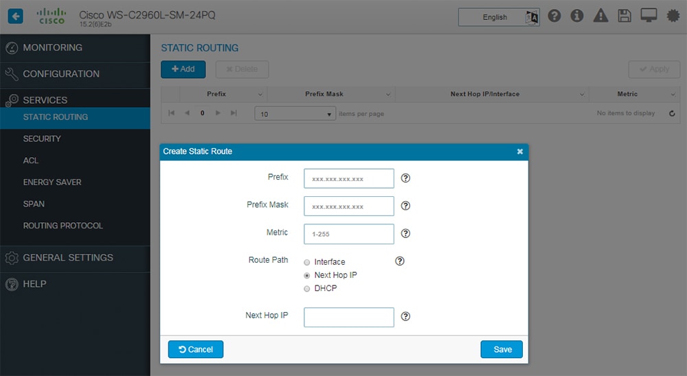
| Step 1 |
Choose Services > Static Routing, and click Add. |
| Step 2 |
In the Prefix and Prefix Mask fields, type the IP address and the subnet mask for the static route. |
| Step 3 |
In the Metric field, assign a metric, between 1 and 255, to the static route. When multiple paths to the same destination are available, the device uses the route with the lowest metric and adds the preferred route into the routing table. |
| Step 4 |
In the Route Path field, choose one of the following options:
The route is removed when the DHCP lease expires. Using DHCP to determine a route path eliminates the need to configure static routes to an outside interface and the configuration of a next-hop router. |
| Step 5 |
Click Save to save the static route. |
 Feedback