- Configuration Example for FIPS
- Configuration Examples for AAA
- Configuration Example for RADIUS
- Configuration Examples for TACACS+
- Configuration Example for SSH
- Configuration Example for SSH Passwordless File Copy
- Configuration Examples for PKI
- Configuration Examples for User Accounts and RBAC
- Configuration Example for 802.1X
- Configuration Example for NAC
- Configuration Examples for Cisco TrustSec
- Enabling Cisco TrustSec
- Configuring AAA for Cisco TrustSec on a Seed Cisco NX-OS Device
- Enabling Cisco TrustSec Authentication on an Interface
- Configuring Cisco TrustSec Authentication in Manual Mode
- Configuring Cisco TrustSec Role-Based Policy Enforcement for the default VRF
- Configuring Cisco TrustSec Role-Based Policy Enforcement for a Nondefault VRF
- Configuring Cisco TrustSec Role-Based Policy Enforcement for a VLAN
- Configuring IPv4 Address to SGACL SGT Mapping for the Default VRF
- Configuring IPv4 Address to SGACL SGT Mapping for a Nondefault VRF
- Configuring IPv4 Address to SGACL SGT Mapping for a VLAN
- Manually Configuring Cisco TrustSec SGACLs
- Manually Configuring SXP Peer Connections
- Configuration Examples for IP ACLs
- Configuration Example for MAC ACLs
- Configuration Example for VACLs
- Configuration Example for Port Security
- Configuration Examples for DHCP
- Configuration Examples for DAI
- Configuration Example for IP Source Guard
- Configuration Examples for Password Encryption
- Configuration Example for Keychain Management
- Configuration Example for Traffic Storm Control
- Configuration Examples for Unicast RPF
- Configuration Examples for CoPP
- Configuration Examples for Rate Limits
Security Configuration Examples
This chapter provides examples for configuring security features.
- Configuration Example for FIPS
- Configuration Examples for AAA
- Configuration Example for RADIUS
- Configuration Examples for TACACS+
- Configuration Example for SSH
- Configuration Example for SSH Passwordless File Copy
- Configuration Examples for PKI
- Configuration Examples for User Accounts and RBAC
- Configuration Example for 802.1X
- Configuration Example for NAC
- Configuration Examples for Cisco TrustSec
- Configuration Examples for IP ACLs
- Configuration Example for MAC ACLs
- Configuration Example for VACLs
- Configuration Example for Port Security
- Configuration Examples for DHCP
- Configuration Examples for DAI
- Configuration Example for IP Source Guard
- Configuration Examples for Password Encryption
- Configuration Example for Keychain Management
- Configuration Example for Traffic Storm Control
- Configuration Examples for Unicast RPF
- Configuration Examples for CoPP
- Configuration Examples for Rate Limits
Configuration Example for FIPS
The following example shows how to enable FIPS mode:
config terminal
fips mode enable
show fips status
exit
copy running-config startup-config
reload
Configuration Examples for AAA
The following example shows how to configure AAA:
aaa authentication login default group radius
aaa authentication login console group radius
aaa accounting default group radius
Configuration Example for RADIUS
The following example shows how to configure RADIUS:
radius-server key 7 "ToIkLhPpG"
radius-server host 10.10.1.1 key 7 "ShMoMhTl" authentication accounting
aaa group server radius RadServer
    server 10.10.1.1
Configuration Examples for TACACS+
The following example shows how to configure a TACACS+ server host and server group:
feature tacacs+
tacacs-server key 7 "ToIkLhPpG"
tacacs-server host 10.10.2.2 key 7 "ShMoMhTl"
aaa group server tacacs+ TacServer
    server 10.10.2.2
The following example shows how to configure and use command authorization verification:
switch# terminal verify-only
switch# show interface ethernet 7/2 brief
%Success
switch# terminal no verify-only
switch# show interface ethernet 7/2 brief

--------------------------------------------------------------------------------
Ethernet      VLAN   Type Mode   Status  Reason                   Speed     Port
Interface                                                                   Ch #
--------------------------------------------------------------------------------
Eth7/2        1      eth  access down    SFP not inserted           auto(D) --
The following example shows how to enable the cumulative privilege of roles, configure a secret password for privilege level 2, and configure user3 for privilege level 2 authorization:
switch# configure terminal
switch(config)# feature privilege
switch(config)# enable secret def456 priv-lvl 2
switch(config)# username user3 priv-lvl 2
switch(config)# show privilege
User name: user3
Current privilege level: -2
Feature privilege: Enabled
switch(config)# copy running-config startup-config
switch(config)# exit
The following example shows how to change user3 from the priv-2 role to the priv-15 role. After entering the enable 15 command, the user is prompted to enter the password that was configured by the administrator using the enable secret command. Privilege level 15 gives this user network-admin privileges under the enable mode.
User Access Verification
login: user3
Password: ******
Cisco Nexus Operating System (NX-OS) Software
TAC support: http://www.cisco.com/tac
Copyright ©) 2002-2009, Cisco Systems, Inc. All rights reserved.
The copyrights to certain works contained in this software are
owned by other third parties and used and distributed under
license. Certain components of this software are licensed under
the GNU General Public License (GPL) version 2.0 or the GNU
Lesser General Public License (LGPL) Version 2.1. A copy of each
such license is available at
http://www.opensource.org/licenses/gpl-2.0.php and
http://www.opensource.org/licenses/lgpl-2.1.php
switch#
switch# enable 15
Password: def456
Cisco Nexus Operating System (NX-OS) Software
TAC support: http://www.cisco.com/tac
Copyright ©) 2002-2009, Cisco Systems, Inc. All rights reserved.
The copyrights to certain works contained in this software are
owned by other third parties and used and distributed under
license. Certain components of this software are licensed under
the GNU General Public License (GPL) version 2.0 or the GNU
Lesser General Public License (LGPL) Version 2.1. A copy of each
such license is available at
http://www.opensource.org/licenses/gpl-2.0.php and
http://www.opensource.org/licenses/lgpl-2.1.php
switch-enable#
The following example shows how to permit all users with roles priv-5 and above to execute the pwd command:
switch# configure terminal
switch(config)# role name priv-5
switch(config-role)# rule 1 permit command pwd
The following example shows how to deny the show running-config command to all users with roles below priv-5. First, you must remove the permission to execute this command from the priv-0 role; then you must permit the command at role priv-5 so that users with roles priv-5 and above have permission to run the command.
switch# configure terminal
switch(config)# role name priv-0
switch(config-role)# rule 2 deny command show running-config
switch(config-role)# exit
switch(config)# role name priv-5
switch(config-role)# rule 3 permit command show running-config
switch(config-role)# exit
Configuration Example for SSH
The following example shows how to configure SSH with an OpenSSH key:
Configuration Example for SSH Passwordless File Copy
The following example shows how to copy files from a Cisco NX-OS device to a secure copy (SCP) or secure FTP (SFTP) server without a password:
Configuration Examples for PKI
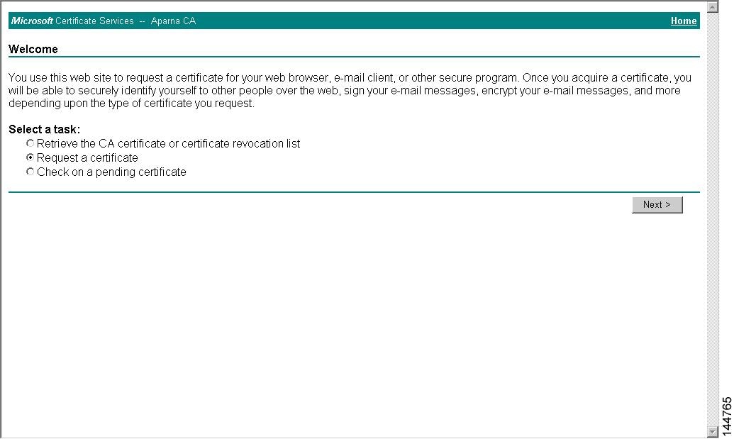
This section shows examples of the tasks that you can use to configure certificates and CRLs on Cisco NX-OS devices using a Microsoft Windows Certificate server.
 Note |
You can use any type of certificate server to generate digital certificates. You are not limited to using the Microsoft Windows Certificate server. |
- Configuring Certificates on a Cisco NX-OS Device
- Downloading a CA Certificate
- Requesting an Identity Certificate
- Revoking a Certificate
- Generating and Publishing the CRL
- Downloading the CRL
- Importing the CRL
Configuring Certificates on a Cisco NX-OS Device
To configure certificates on a Cisco NX-OS device, follow these steps:
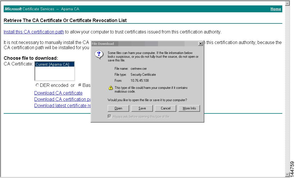
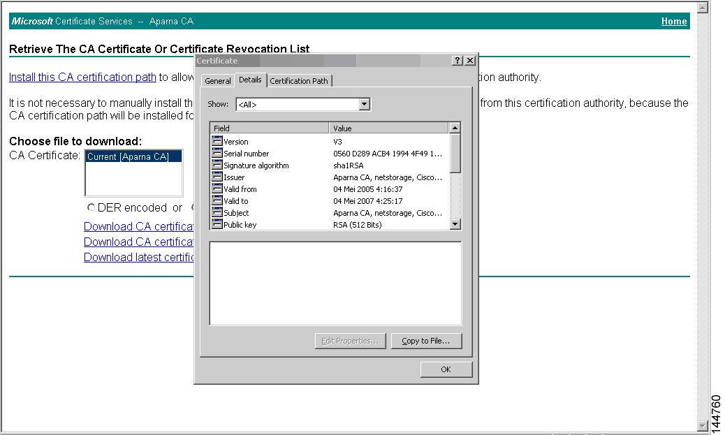
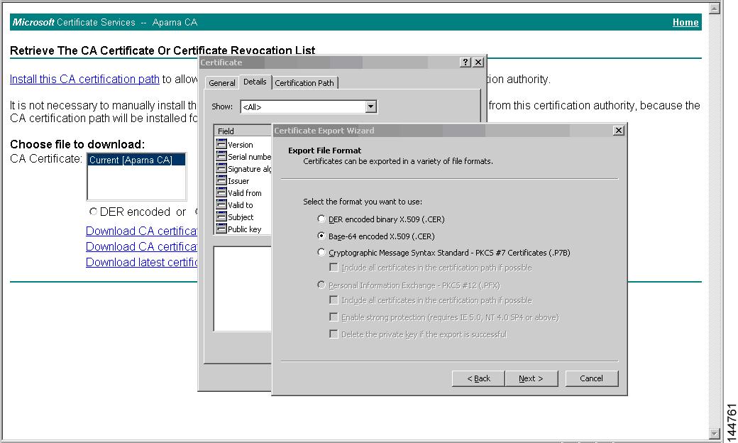
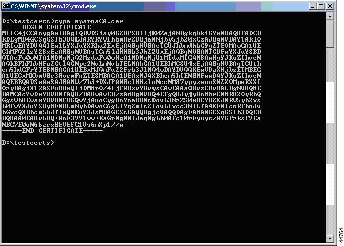
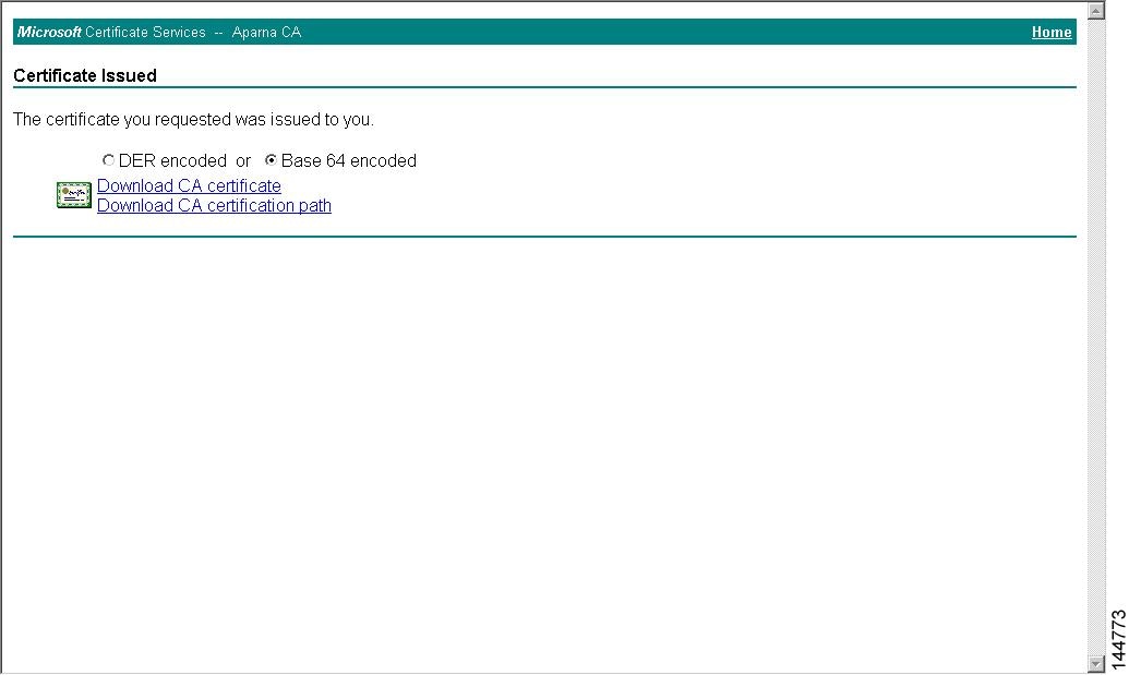
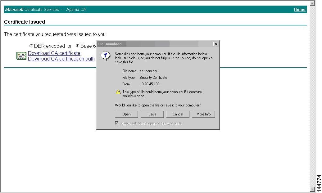
Downloading a CA Certificate
To download a CA certificate from the Microsoft Certificate Services web interface, follow these steps:


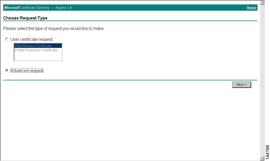
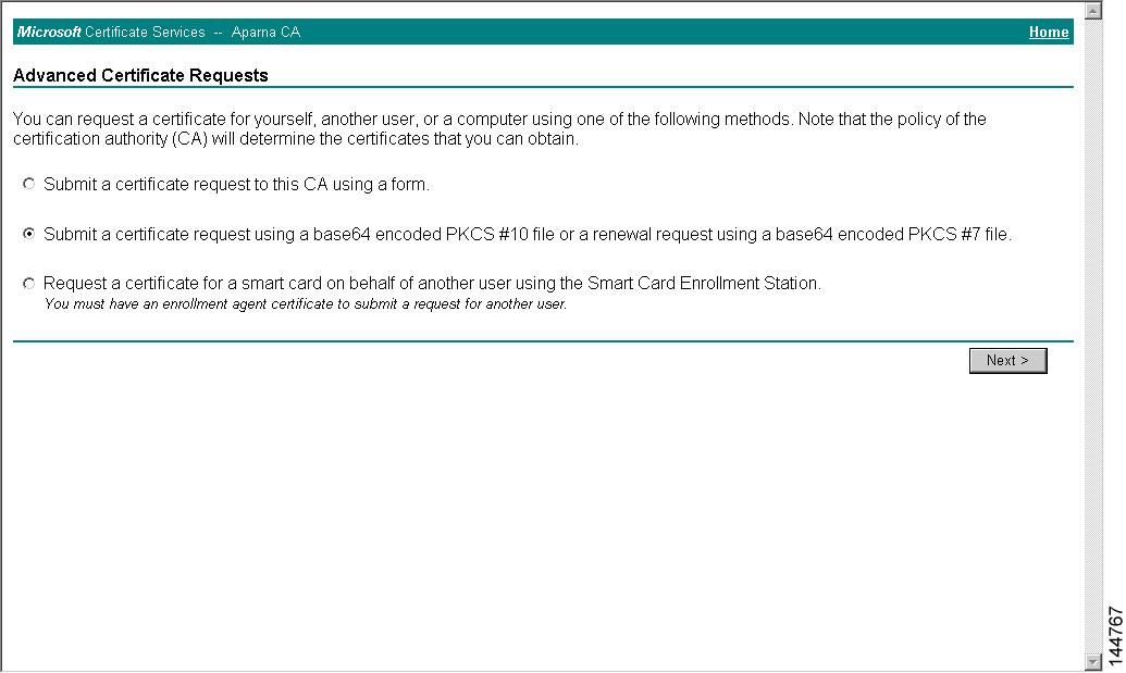
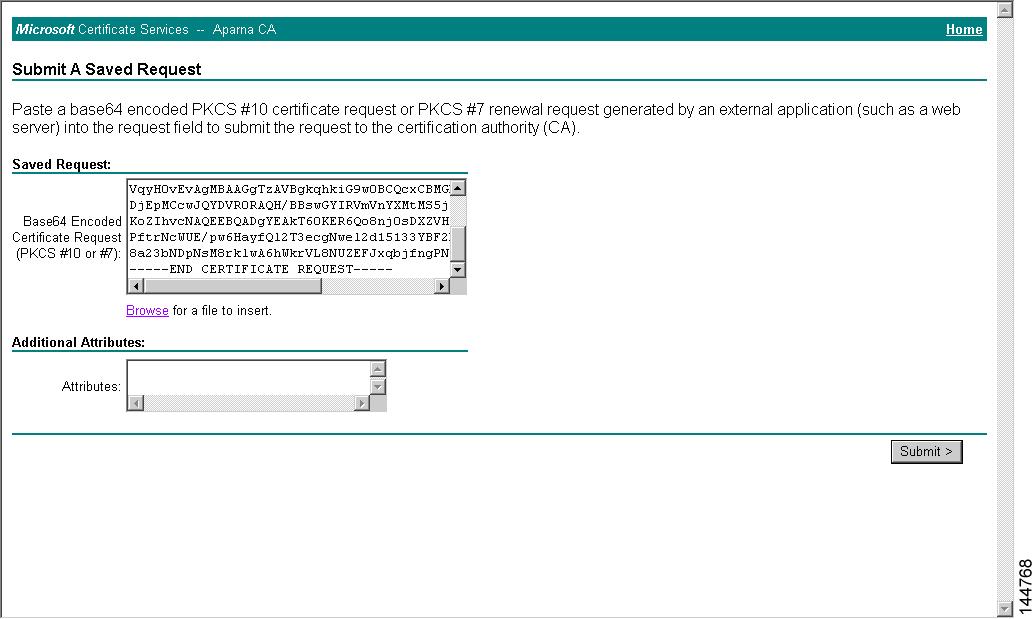
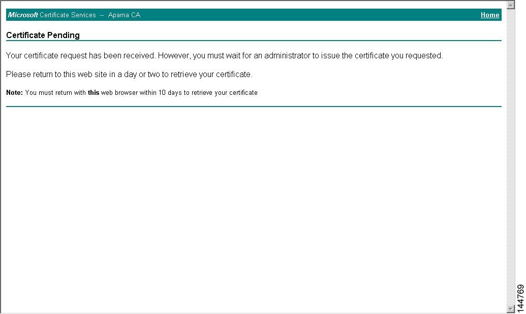
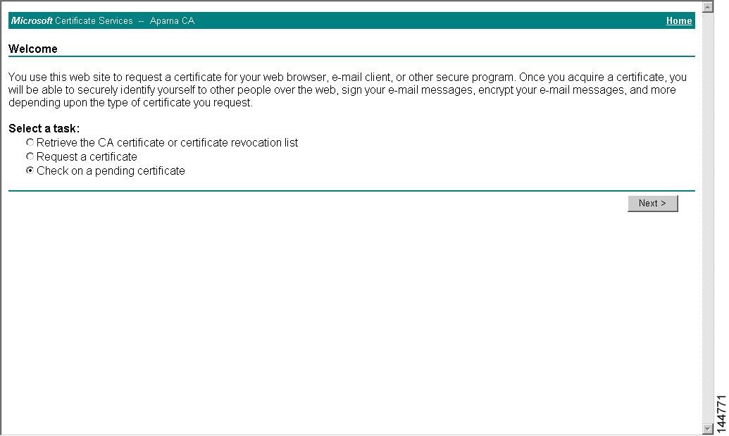
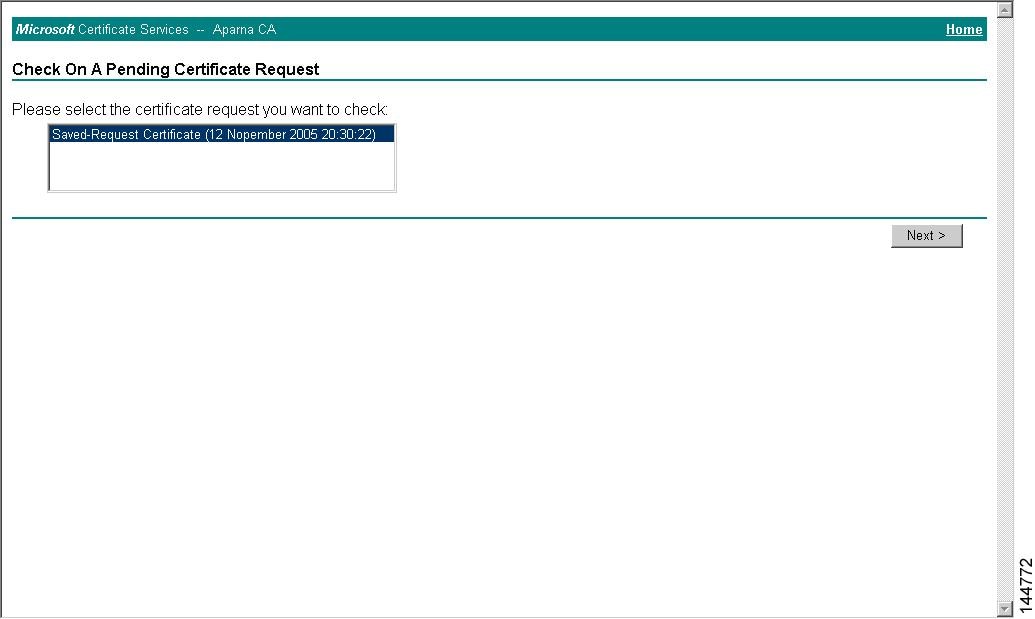
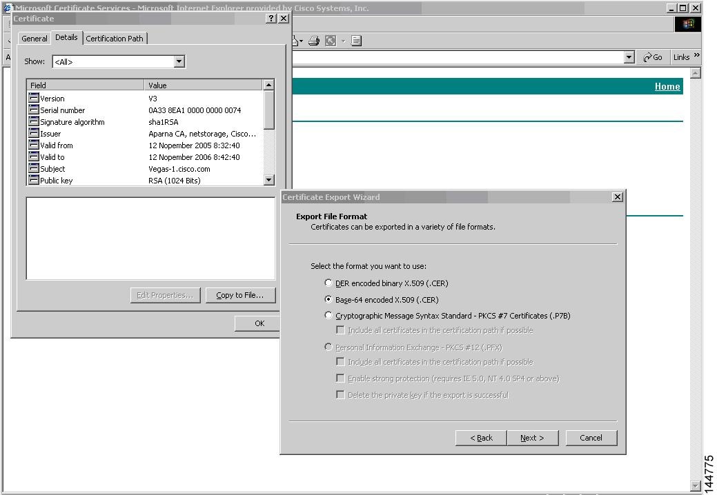
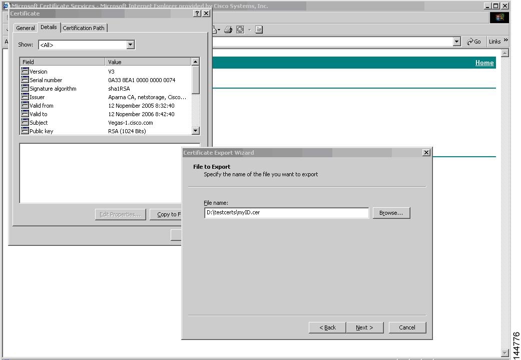
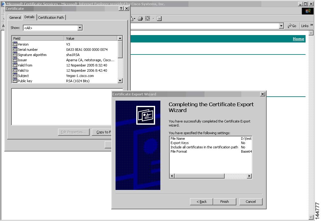
Requesting an Identity Certificate
To request an identify certificate from a Microsoft Certificate server using a PKCS#12 certificate signing request (CRS), follow these steps:
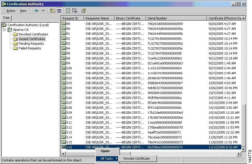
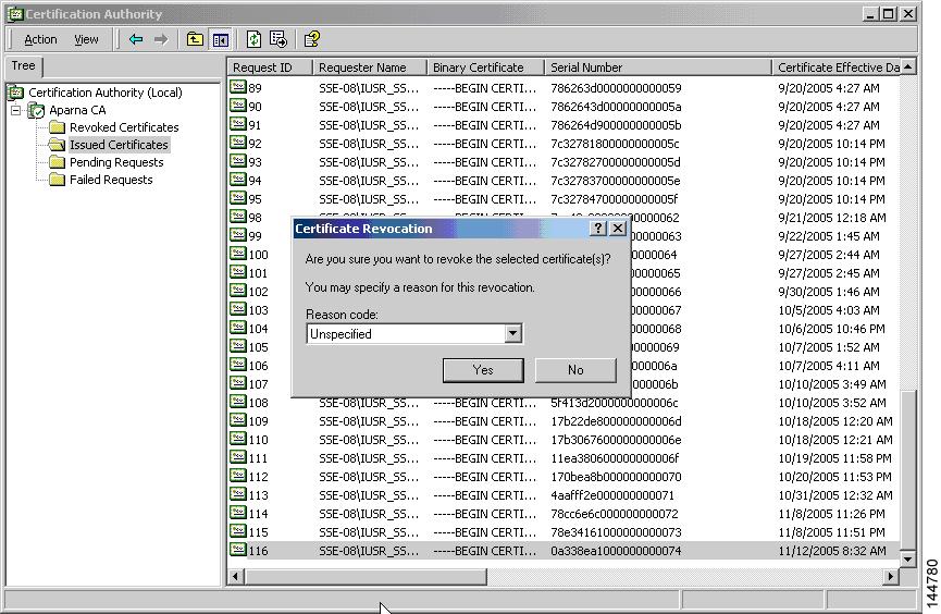
Revoking a Certificate
To revoke a certificate using the Microsoft CA administrator program, follow these steps:
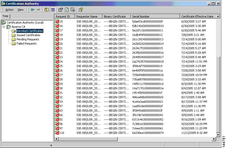
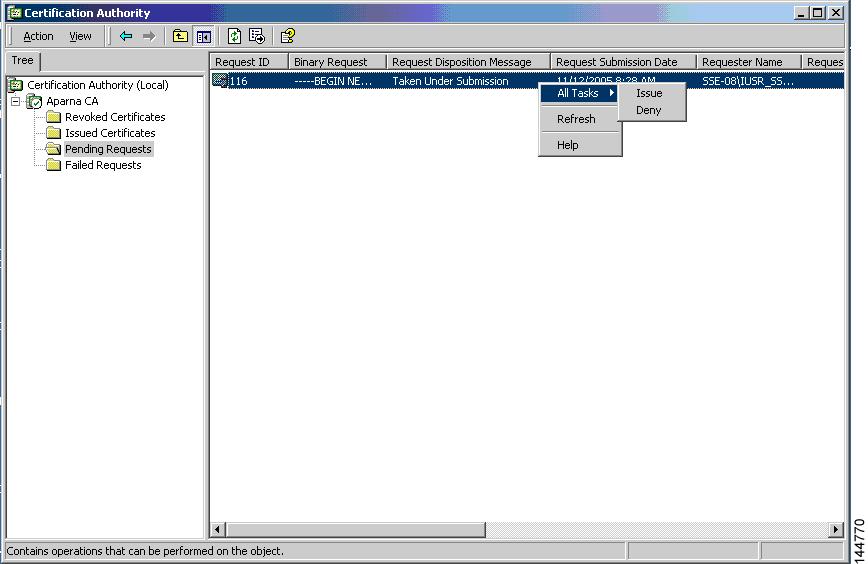
Generating and Publishing the CRL
To generate and publish the CRL using the Microsoft CA administrator program, follow these steps:
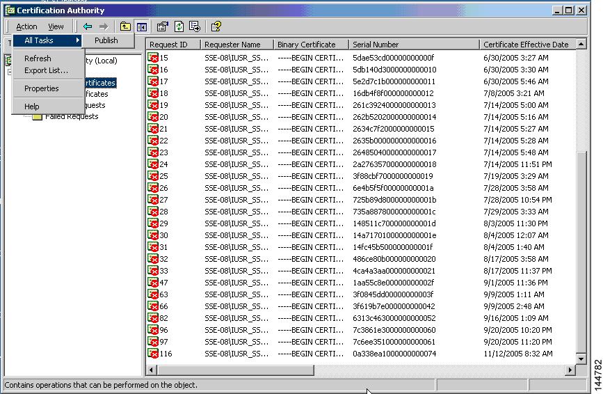
| Step 1 |
From the Certification Authority screen, choose Action > All Tasks > Publish.
 |
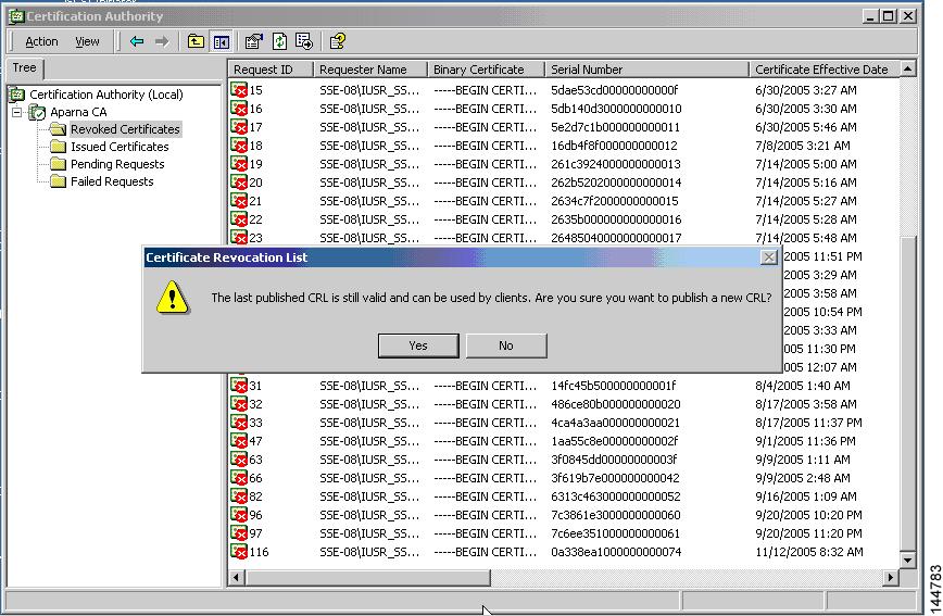
| Step 2 |
In the Certificate Revocation List dialog box, click Yes to publish the latest CRL.
 |
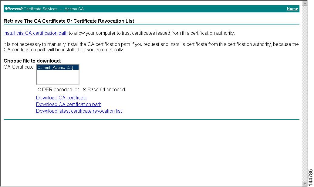
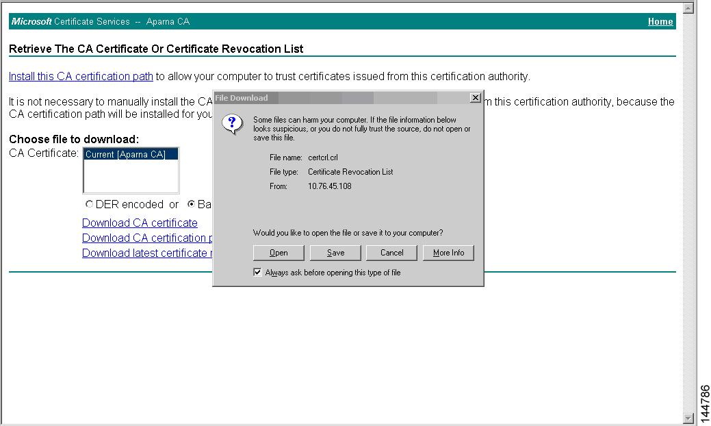
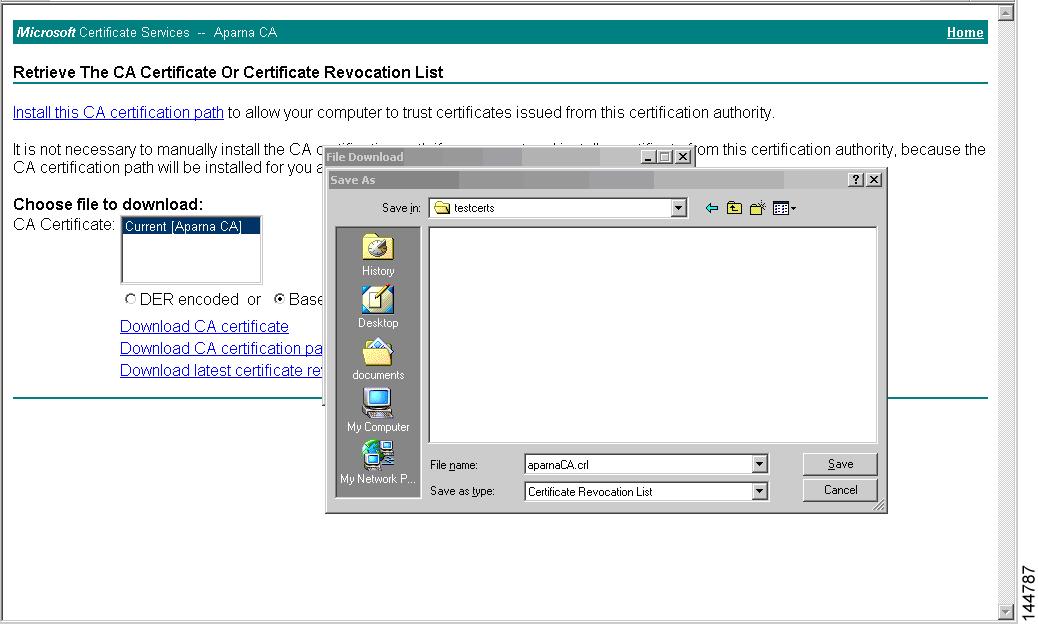
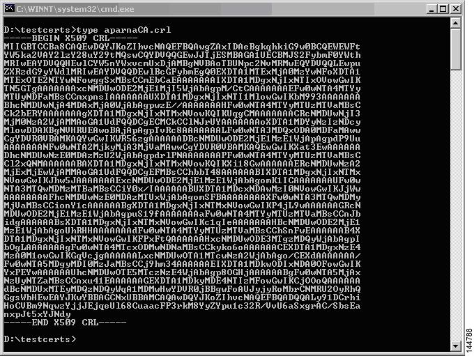
Downloading the CRL
To download the CRL from the Microsoft CA website, follow these steps:

Importing the CRL
To import the CRL to the trust point corresponding to the CA, follow these steps:
Configuration Examples for User Accounts and RBAC
The following example shows how to configure a user role:
role name User-role-A
  rule 3 permit read-write feature l2nac
  rule 2 permit read-write feature dot1x
  rule 1 deny command clear *
The following example shows how to create a user role that can configure an interface to enable and show HSRP and show GLBP:
role name iftest
	  rule 1 permit command config t; interface *; hsrp *
	  rule 2 permit read-write feature hsrp
	  rule 3 permit read feature glbp
In the above example, rule 1 allows you to configure HSRP on an interface, rule 2 allows you to configure the config hsrp commands and enable the exec-level show and debug commands for HSRP, and rule 3 allows you to enable the exec-level show and debug glbp commands.
The following example shows how to configure a user role that can configure only a specific interface:
role name Int_Eth2-3_only
  rule 1 permit command configure terminal; interface *
  interface policy deny
    permit interface Ethernet2/3
The following example shows how to configure a user role feature group:
role feature-group name Security-features
  feature radius
  feature tacacs
  feature dot1x
  feature aaa
  feature l2nac
  feature acl
  feature access-list
The following example shows how to configure a user account:
username user1 password A1s2D4f5 role User-role-A
Configuration Example for 802.1X
The following example shows how to configure 802.1X:
feature dot1x
aaa authentication dot1x default group rad2
interface Ethernet2/1
  dot1x port-control auto
Note |
Repeat the dot1x port-control auto command for all interfaces that require 802.1X authentication. |
Configuration Example for NAC
The following example shows how to configure NAC:
feature eou
aaa authentication eou default group radius
mac access-list macacl-01
  10 permit any any 0x100
interface Ethernet8/1
  mac access-group macacl-01
Configuration Examples for Cisco TrustSec
This section provides configuration examples for Cisco TrustSec.
- Enabling Cisco TrustSec
- Configuring AAA for Cisco TrustSec on a Seed Cisco NX-OS Device
- Enabling Cisco TrustSec Authentication on an Interface
- Configuring Cisco TrustSec Authentication in Manual Mode
- Configuring Cisco TrustSec Role-Based Policy Enforcement for the default VRF
- Configuring Cisco TrustSec Role-Based Policy Enforcement for a Nondefault VRF
- Configuring Cisco TrustSec Role-Based Policy Enforcement for a VLAN
- Configuring IPv4 Address to SGACL SGT Mapping for the Default VRF
- Configuring IPv4 Address to SGACL SGT Mapping for a Nondefault VRF
- Configuring IPv4 Address to SGACL SGT Mapping for a VLAN
- Manually Configuring Cisco TrustSec SGACLs
- Manually Configuring SXP Peer Connections
Enabling Cisco TrustSec
The following example shows how to enable Cisco TrustSec:
feature dot1x
feature cts
cts device-id device1 password Cisco321
Configuring AAA for Cisco TrustSec on a Seed Cisco NX-OS Device
The following example shows how to configure AAA for Cisco TrustSec on the seed Cisco NX-OS device:
radius-server host 10.10.1.1 key Cisco123 pac
aaa group server radius Rad1
  server 10.10.1.1
  use-vrf management
aaa authentication dot1x default group Rad1
aaa authorization cts default group Rad1
Enabling Cisco TrustSec Authentication on an Interface
The following example shows how to enable Cisco TrustSec authentication with a clear text password on an interface:
interface ethernet 2/1
  cts dot1x
  shutdown
  no shutdown
Configuring Cisco TrustSec Authentication in Manual Mode
The following example shows how to configure Cisco TrustSec authentication in manual mode static policy on an interface:
interface ethernet 2/1
  cts manual
    sap pmk abcdef modelist gmac
    policy static sgt 0x20
The following example shows how to configure Cisco TrustSec authentication in manual mode dynamic policy on an interface:
interface ethernet 2/2
  cts manual
    policy dynamic identity device2
Configuring Cisco TrustSec Role-Based Policy Enforcement for the default VRF
The following example shows how to enable Cisco TrustSec role-based policy enforcement for the default VRF:
cts role-based enforcement
Configuring Cisco TrustSec Role-Based Policy Enforcement for a Nondefault VRF
The following example shows how to enable Cisco TrustSec role-based policy enforcement for a nondefault VRF:
vrf context test
  cts role-based enforcement
Configuring Cisco TrustSec Role-Based Policy Enforcement for a VLAN
The following example shows how to enable Cisco TrustSec role-based policy enforcement for a VLAN:
vlan 10
  cts role-based enforcement
Configuring IPv4 Address to SGACL SGT Mapping for the Default VRF
The following example shows how to manually configure IPv4 address to SGACL SGT mapping for Cisco TrustSec role-based policies for the default VRF:
cts role-based sgt-map 10.1.1.1 20
Configuring IPv4 Address to SGACL SGT Mapping for a Nondefault VRF
The following example shows how to manually configure IPv4 address to SGACL SGT mapping for Cisco TrustSec role-based policies for a nondefault VRF:
vrf context test
  cts role-based sgt-map 30.1.1.1 30
Configuring IPv4 Address to SGACL SGT Mapping for a VLAN
The following example shows how to manually configure IPv4 address to SGACL SGT mapping for Cisco TrustSec role-based policies for a VLAN:
vlan 10
  cts role-based sgt-map 20.1.1.1 20
Manually Configuring Cisco TrustSec SGACLs
The following example shows how to manually configure Cisco TrustSec SGACLs:
cts role-based access-list abcd
  permit icmp
cts role-based sgt 10 dgt 20 access-list abcd
The following example shows how to enable RBACL logging:
cts role-based access-list RBACL1
deny tcp src eq 1111 dest eq 2222 log
cts role-based sgt 10 dgt 20 access-list RBACL1
cts role-based sgt-map 1.1.1.1 10
cts role-based sgt-map 1.1.1.2 20
%ACLLOG-6-ACLLOG_FLOW_INTERVAL: SGT: 10, Source IP: 1.1.1.1, Destination IP: 1.1.1.2, Source Port: 1111, Destination Port: 2222, Source Interface: Ethernet4/1, Protocol: tcp, Hit-count = 2
Note |
The ACLLOG syslog does not contain the destination group tag (DGT) information of the matched RBACL policy. You can find this information by looking up the IP-SGT mapping of the destination IP address in the log message and then entering the show cts role-based sgt-map command. |
The following example shows how to enable and display RBACL statistics:
cts role-based counters enable
show cts role-based counters sgt 10 dgt 20

RBACL policy counters enabled
sgt: 10 dgt: 20 [180]
rbacl test1:
deny tcp src eq 1111 dest eq 2222   [75]
deny tcp src eq 2222 dest eq 3333   [25]
rbacl test2:
deny udp src eq 1111 dest eq 2222   [30]
deny udp src eq 2222 dest eq 3333   [50]
Manually Configuring SXP Peer Connections
Figure 1. Example SXP Peer Connections
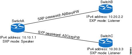
The following example shows how to configure the SXP peer connections on SwitchA:
feature cts
cts role-based enforcement
cts sxp enable
cts sxp connection peer 10.20.2.2 password required A2BsxpPW mode listener
cts sxp connection peer 10.30.3.3 password required A2CsxpPW mode listener
The following example shows how to configure the SXP peer connection on SwitchB:
feature cts
cts role-based enforcement
cts sxp enable
cts sxp connection peer 10.10.1.1 password required A2BsxpPW mode speaker
The following example shows how to configure the SXP peer connection on SwitchC:
feature cts
cts role-based enforcement
cts sxp enable
cts sxp connection peer 10.10.1.1 password required A2CsxpPW mode speaker
Configuration Examples for IP ACLs
The following example shows how to create an IPv4 ACL named acl-01 and apply it as a port ACL to Ethernet interface 2/1, which is a Layer 2 interface:
ip access-list acl-01
  permit ip 192.168.2.0/24 any
interface ethernet 2/1
  ip port access-group acl-01 in
The following example shows how to create an IPv6 ACL named acl-120 and apply it as a router ACL to Ethernet interface 2/3, which is a Layer 3 interface:
ipv6 access-list acl-120
  permit tcp 2001:0db8:85a3::/48 2001:0db8:be03:2112::/64
  permit udp 2001:0db8:85a3::/48 2001:0db8:be03:2112::/64
  permit tcp 2001:0db8:69f2::/48 2001:0db8:be03:2112::/64
  permit udp 2001:0db8:69f2::/48 2001:0db8:be03:2112::/64
interface ethernet 2/3
  ipv6 traffic-filter acl-120 in
The following example shows how to create a VTY ACL named single-source and apply it on input IP traffic over the VTY line. This ACL allows all TCP traffic through and drops all other IP traffic:
ip access-list single-source
		permit tcp 192.168.7.5/24 any
		exit
		line vty
		ip access-class single-source in
		show ip access-lists
The following example shows how to enable ACL capture in the default VDC and configure a destination for ACL capture packets:
hardware access-list capture
		monitor session 1 type acl-capture
		destination interface ethernet 2/1
		no shut
		exit
		show ip access-lists capture session 1
The following example shows how to enable a capture session for an ACL's access control entries (ACEs) and then apply the ACL to an interface:
ip access-list acl1
		permit tcp any any capture session 1
		exit
		interface ethernet 1/11
		ip access-group acl1 in
		no shut
		show running-config aclmgr
The following example shows how to apply an ACL with capture session access control entries (ACEs) to a VLAN:
vlan access-map acl-vlan-first
		match ip address acl-ipv4-first
		match mac address acl-mac-first
		action foward
		statistics per-entry
		vlan filter acl-vlan-first vlan-list 1
		show running-config vlan 1
The following example shows how to enable a capture session for the whole ACL and then apply the ACL to an interface:
ip access-list acl2
		capture session 2
		exit
		interface ethernet 7/1
		ip access-group acl1 in
		no shut
		show running-config aclmgr
Configuration Example for MAC ACLs
The following example shows how to create a MAC ACL named acl-mac-01 and apply it to Ethernet interface 2/1, which is a Layer 2 interface in this example:
mac access-list acl-mac-01
  permit 00c0.4f00.0000 0000.00ff.ffff any
interface ethernet 2/1
  mac port access-group acl-mac-01
Configuration Example for VACLs
The following example shows how to configure a VACL to forward traffic permitted by a MAC ACL named acl-mac-01 and how to apply the VACL to VLANs 50 through 82.
conf t
vlan access-map acl-mac-map
  match mac address acl-mac-01
  action forward
vlan filter acl-mac-map vlan-list 50-82
Configuration Example for Port Security
The following example shows a port security configuration for the Ethernet 2/1 interface with VLAN and interface maximums for secure addresses. In this example, the interface is a trunk port. Additionally, the violation action is set to Restrict.
feature port-security
interface Ethernet 2/1
  switchport
  switchport port-security
  switchport port-security maximum 10
  switchport port-security maximum 7 vlan 10
  switchport port-security maximum 3 vlan 20
  switchport port-security violation restrict
Configuration Examples for DHCP
This example shows how to enable DHCP snooping on two VLANs, with Option 82 support enabled and Ethernet interface 2/5 trusted because the DHCP server is connected to that interface:
feature dhcp
ip dhcp snooping
ip dhcp snooping info option

interface Ethernet 2/5
  ip dhcp snooping trust
ip dhcp snooping vlan 1
ip dhcp snooping vlan 50
This example shows how to enable the DHCP relay agent and configure the DHCP server IP address for Ethernet interface 2/3, where the DHCP server IP address is 10.132.7.120 and the DHCP server is in the VRF named red:
feature dhcp
ip dhcp snooping
ip dhcp relay
ip dhcp relay information option
ip dhcp relay information option vpn

interface Ethernet 2/3
  ip dhcp relay address 10.132.7.120 use-vrf red
This example shows how to enable and use the DHCP smart relay agent. In this example, the switch forwards the DHCP broadcast packets received on Ethernet interface 2/2 to the DHCP server (10.55.11.3), inserting 192.168.100.1 in the giaddr field. If the DHCP server has a pool configured for the 192.168.100.0/24 network, it responds. If the server does not respond, the switch sends two more requests using 192.168.100.1 in the giaddr field. If the switch still does not receive a response, it starts using 172.16.31.254 in the giaddr field instead.
feature dhcp
ip dhcp snooping
ip dhcp relay
ip dhcp smart-relay global

interface Ethernet 2/2
		ip address 192.168.100.1/24
		ip address 172.16.31.254/24 secondary
		ip dhcp relay address 10.55.11.3
Configuration Examples for DAI
Example 1 Two Devices Support DAI
These procedures show how to configure DAI when two devices support DAI.
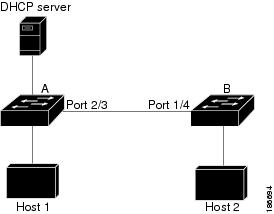
This figure shows the network configuration for this example. Host 1 is connected to device A, and Host 2 is connected to device B. Both devices are running DAI on VLAN 1 where the hosts are located. A DHCP server is connected to device A. Both hosts acquire their IP addresses from the same DHCP server. Device A has the bindings for Host 1 and Host 2, and device B has the binding for Host 2. Device A Ethernet interface 2/3 is connected to the device B Ethernet interface 1/4.
Figure 2. Two Devices Supporting DAI
DAI depends on the entries in the DHCP snooping binding database to verify IP-to-MAC address bindings in incoming ARP requests and ARP responses. Make sure to enable DHCP snooping to permit ARP packets that have dynamically-assigned IP addresses.
Configuring Device A
To enable DAI and configure Ethernet interface 2/3 on device A as trusted, follow these steps:
| Step 1 |
While logged into device A, verify the connection between device A and device B. Example: switchA# show cdp neighbors
Capability Codes: R - Router, T - Trans-Bridge, B - Source-Route-Bridge
S - Switch, H - Host, I - IGMP, r - Repeater,
V - VoIP-Phone, D - Remotely-Managed-Device,
s - Supports-STP-Dispute
Device ID Local Intrfce Hldtme Capability Platform Port ID
switchB Ethernet2/3 177 R S I WS-C2960-24TC Ethernet1/4
switchA#
|
| Step 2 |
Enable DAI on VLAN 1 and verify the configuration. Example: switchA# config t switchA(config)# ip arp inspection vlan 1 switchA(config)# show ip arp inspection vlan 1 Source Mac Validation : Disabled Destination Mac Validation : Disabled IP Address Validation : Disabled Vlan : 1 ----------- Configuration : Enabled Operation State : Active switchA(config)# |
| Step 3 |
Configure Ethernet interface 2/3 as trusted. Example: switchA(config)# interface ethernet 2/3 switchA(config-if)# ip arp inspection trust switchA(config-if)# exit switchA(config)# exit switchA# show ip arp inspection interface ethernet 2/3 Interface Trust State Rate (pps) Burst Interval ------------- ----------- ---------- -------------- Ethernet2/3 Trusted 15 5 |
| Step 4 |
Verify the bindings. Example: switchA# show ip dhcp snooping binding MacAddress IpAddress LeaseSec Type VLAN Interface ----------------- --------------- -------- ------------- ---- ------------- 00:60:0b:00:12:89 10.0.0.1 0 dhcp-snooping 1 Ethernet2/3 switchA# |
| Step 5 |
Check the statistics before and after DAI processes any packets. Example: switchA# show ip arp inspection statistics vlan 1 Vlan : 1 ----------- ARP Req Forwarded = 0 ARP Res Forwarded = 0 ARP Req Dropped = 0 ARP Res Dropped = 0 DHCP Drops = 0 DHCP Permits = 0 SMAC Fails-ARP Req = 0 SMAC Fails-ARP Res = 0 DMAC Fails-ARP Res = 0 IP Fails-ARP Req = 0 IP Fails-ARP Res = 0 switchA# If Host 1 sends out two ARP requests with an IP address of 10.0.0.1 and a MAC address of 0002.0002.0002, both requests are permitted, shown as follows: switchA# show ip arp inspection statistics vlan 1 Vlan : 1 ----------- ARP Req Forwarded = 2 ARP Res Forwarded = 0 ARP Req Dropped = 0 ARP Res Dropped = 0 DHCP Drops = 0 DHCP Permits = 2 SMAC Fails-ARP Req = 0 SMAC Fails-ARP Res = 0 DMAC Fails-ARP Res = 0 IP Fails-ARP Req = 0 IP Fails-ARP Res = 0 If Host 1 tries to send an ARP request with an IP address of 10.0.0.3, the packet is dropped and an error message is logged. 00:12:08: %SW_DAI-4-DHCP_SNOOPING_DENY: 2 Invalid ARPs (Req) on Ethernet2/3, vlan 1.([0002.0002.0002/10.0.0.3/0000.0000.0000/0.0.0.0/02:42:35 UTC Fri Jul 13 2008]) The statistics display as follows: switchA# show ip arp inspection statistics vlan 1 switchA# Vlan : 1 ----------- ARP Req Forwarded = 2 ARP Res Forwarded = 0 ARP Req Dropped = 2 ARP Res Dropped = 0 DHCP Drops = 2 DHCP Permits = 2 SMAC Fails-ARP Req = 0 SMAC Fails-ARP Res = 0 DMAC Fails-ARP Res = 0 IP Fails-ARP Req = 0 IP Fails-ARP Res = 0 switchA# |
Configuring Device B
To enable DAI and configure Ethernet interface 1/4 on device B as trusted, follow these steps:
| Step 1 |
While logged into device B, verify the connection between device B and device A. Example: switchB# show cdp neighbors
Capability Codes: R - Router, T - Trans-Bridge, B - Source-Route-Bridge
S - Switch, H - Host, I - IGMP, r - Repeater,
V - VoIP-Phone, D - Remotely-Managed-Device,
s - Supports-STP-Dispute
Device ID Local Intrfce Hldtme Capability Platform Port ID
switchA Ethernet1/4 120 R S I WS-C2960-24TC Ethernet2/3
switchB#
|
| Step 2 |
Enable DAI on VLAN 1, and verify the configuration. Example: switchB# config t switchB(config)# ip arp inspection vlan 1 switchB(config)# show ip arp inspection vlan 1 Source Mac Validation : Disabled Destination Mac Validation : Disabled IP Address Validation : Disabled Vlan : 1 ----------- Configuration : Enabled Operation State : Active switchB(config)# |
| Step 3 |
Configure Ethernet interface 1/4 as trusted. Example: switchB(config)# interface ethernet 1/4 switchB(config-if)# ip arp inspection trust switchB(config-if)# exit switchB(config)# exit switchB# show ip arp inspection interface ethernet 1/4 Interface Trust State Rate (pps) Burst Interval ------------- ----------- ---------- -------------- Ethernet1/4 Trusted 15 5 switchB# |
| Step 4 |
Verify the list of DHCP snooping bindings. Example: switchB# show ip dhcp snooping binding MacAddress IpAddress LeaseSec Type VLAN Interface ----------------- --------------- -------- ------------- ---- ------------- 00:01:00:01:00:01 10.0.0.2 4995 dhcp-snooping 1 Ethernet1/4 switchB# |
| Step 5 |
Check the statistics before and after DAI processes any packets. Example: switchB# show ip arp inspection statistics vlan 1 Vlan : 1 ----------- ARP Req Forwarded = 0 ARP Res Forwarded = 0 ARP Req Dropped = 0 ARP Res Dropped = 0 DHCP Drops = 0 DHCP Permits = 0 SMAC Fails-ARP Req = 0 SMAC Fails-ARP Res = 0 DMAC Fails-ARP Res = 0 IP Fails-ARP Req = 0 IP Fails-ARP Res = 0 switchB# If Host 2 sends out an ARP request with the IP address 10.0.0.2 and the MAC address 0001.0001.0001, the packet is forwarded and the statistics are updated. switchB# show ip arp inspection statistics vlan 1 Vlan : 1 ----------- ARP Req Forwarded = 1 ARP Res Forwarded = 0 ARP Req Dropped = 0 ARP Res Dropped = 0 DHCP Drops = 0 DHCP Permits = 1 SMAC Fails-ARP Req = 0 SMAC Fails-ARP Res = 0 DMAC Fails-ARP Res = 0 IP Fails-ARP Req = 0 IP Fails-ARP Res = 0 switchB# If Host 2 attempts to send an ARP request with the IP address 10.0.0.1, DAI drops the request and logs the following system message: 00:18:08: %SW_DAI-4-DHCP_SNOOPING_DENY: 1 Invalid ARPs (Req) on Ethernet1/4, vlan 1.([0001.0001.0001/10.0.0.1/0000.0000.0000/0.0.0.0/01:53:21 UTC Fri Jun 13 2008]) The statistics display as follows: switchB# show ip arp inspection statistics vlan 1 Vlan : 1 ----------- ARP Req Forwarded = 1 ARP Res Forwarded = 0 ARP Req Dropped = 1 ARP Res Dropped = 0 DHCP Drops = 1 DHCP Permits = 1 SMAC Fails-ARP Req = 0 SMAC Fails-ARP Res = 0 DMAC Fails-ARP Res = 0 IP Fails-ARP Req = 0 IP Fails-ARP Res = 0 switchB# |
Example 2 One Device Supports DAI
This procedure shows how to configure DAI when the second device involved in the network configuration does not support DAI or DHCP snooping.
Device B, shown in this figure does not support DAI or DHCP snooping; therefore, configuring Ethernet interface 2/3 on device A as trusted creates a security hole because both device A and Host 1 could be attacked by either device B or Host 2.
To prevent this possibility, you must configure Ethernet interface 2/3 on device A as untrusted. To permit ARP packets from Host 2, you must set up an ARP ACL and apply it to VLAN 1. If the IP address of Host 2 is not static, which would make it impossible to accurately configure the ARP ACL on device A, you must separate device A from device B at Layer 3 and use a router to route packets between them.
Figure 3. One Device Supporting DAI
| Step 1 |
Configure the access list to permit the IP address 10.0.0.1 and the MAC address 0001.0001.0001, and verify the configuration. Example: switchA# config t switchA(config)# arp access-list H2 switchA(config-arp-acl)# permit ip host 10.0.0.1 mac host 0001.0001.0001 switchA(config-arp-acl)# exit switchA(config)# show arp access-lists H2 ARP access list H2 10 permit ip host 1.1.1.1 mac host 0001.0001.0001 switchA(config)# |
||
| Step 2 |
Apply the ACL to VLAN 1, and verify the configuration. Example: switchA(config)# ip arp inspection filter H2 vlan 1 switchA(config)# show ip arp inspection vlan 1 Source Mac Validation : Disabled Destination Mac Validation : Disabled IP Address Validation : Disabled Vlan : 200 ----------- Configuration : Enabled Operation State : Active ACL Match/Static : H2 / No |
||
| Step 3 |
Configure Ethernet interface 2/3 as untrusted, and verify the configuration.
Example: switchA(config)# interface ethernet 2/3 switchA(config-if)# no ip arp inspection trust switchA(config-if)# exit switchA# show ip arp inspection interface ethernet 2/3 switchA# The show ip arp inspection interface command has no output because the interface has the default configuration, which includes an untrusted state. When Host 2 sends 5 ARP requests through Ethernet interface 2/3 on device A and a "get" is permitted by device A, the statistics are updated. switchA# show ip arp inspection statistics vlan 1 Vlan : 1 ----------- ARP Req Forwarded = 5 ARP Res Forwarded = 0 ARP Req Dropped = 0 ARP Res Dropped = 0 DHCP Drops = 0 DHCP Permits = 0 SMAC Fails-ARP Req = 0 SMAC Fails-ARP Res = 0 DMAC Fails-ARP Res = 0 IP Fails-ARP Req = 0 IP Fails-ARP Res = 0 switchA# |
Configuration Example for IP Source Guard
This example shows how to create a static IP source entry and then how to enable IP Source Guard on an interface.
ip source binding 10.5.22.17 001f.28bd.0013 vlan 100 interface ethernet 2/3
interface ethernet 2/3
  no shutdown
  ip verify source dhcp-snooping-vlan
Configuration Examples for Password Encryption
The following example shows how to create a master key, enable the AES password encryption feature, and configure a type-6 encrypted password for a TACACS+ application:
key config-key ascii
  New Master Key:
  Retype Master Key:
configure terminal
feature password encryption aes
show encryption service stat
		Encryption service is enabled.
  Master Encryption Key is configured.
  Type-6 encryption is being used.
feature tacacs+
tacacs-server key Cisco123
show running-config tacacs+
  feature tacacs+
  logging level tacacs 5
  tacacs-server key 6 "JDYkqyIFWeBvzpljSfWmRZrmRSRE8syxKlOSjP9RCCkFinZbJI3GD5c6rckJR/Qju2PKLmOewbheAA=="
Configuration Example for Keychain Management
This example shows how to configure a keychain named glbp keys. Each key text string is encrypted. Each key has longer accept lifetimes than send lifetimes, to help prevent lost communications by accidentally configuring a time in which there are no active keys.
key chain glbp-keys
  key 0
    key-string 7 zqdest
    accept-lifetime 00:00:00 Jun 01 2008 23:59:59 Sep 12 2008
    send-lifetime 00:00:00 Jun 01 2008 23:59:59 Aug 12 2008
  key 1
    key-string 7 uaeqdyito
    accept-lifetime 00:00:00 Aug 12 2008 23:59:59 Dec 12 2008
    send-lifetime 00:00:00 Sep 12 2008 23:59:59 Nov 12 2008
  key 2
    key-string 7 eekgsdyd
    accept-lifetime 00:00:00 Nov 12 2008 23:59:59 Mar 12 2009
    send-lifetime 00:00:00 Dec 12 2008 23:59:59 Feb 12 2009
Configuration Example for Traffic Storm Control
The following example shows how to configure traffic storm control:
interface Ethernet1/1
  storm-control broadcast level 40
  storm-control multicast level 40
  storm-control unicast level 40
Configuration Examples for Unicast RPF
The following example shows how to configure loose Unicast RFP for IPv4 packets:
interface Ethernet2/3
  ip address 172.23.231.240/23
  ip verify unicast source reachable-via any
The following example shows how to configure strict Unicast RFP for IPv4 packets:
interface Ethernet2/2
  ip address 172.23.231.240/23
  ip verify unicast source reachable-via rx
The following example shows how to configure loose Unicast RFP for IPv6 packets:
interface Ethernet2/1
  ipv6 address 2001:0DB8:c18:1::3/64
  ipv6 verify unicast source reachable-via any
The following example shows how to configure strict Unicast RFP for IPv6 packets:
interface Ethernet2/4
  ipv6 address 2001:0DB8:c18:1::3/64
  ipv6 verify unicast source reachable-via rx
Configuration Examples for CoPP
This section includes example CoPP configurations.
- CoPP Configuration Example
- Changing or Reapplying the Default CoPP Policy Using the Setup Utility
- Preventing CoPP Overflow by Splitting ICMP Pings and ARP Requests
CoPP Configuration Example
The following example shows how to configure CoPP using IP ACLs and MAC ACLs:
configure terminal
ip access-list copp-system-p-acl-igmp
permit igmp any 10.0.0.0/24

ip access-list copp-system-p-acl-msdp
permit tcp any any eq 639

mac access-list copp-system-p-acl-arp
permit any any 0x0806

ip access-list copp-system-p-acl-tacas
permit udp any any eq 49

ip access-list copp-system-p-acl-gre
permit 47 any any

ip access-list copp-system-p-acl-ntp
permit udp any 10.0.1.1/23 eq 123

ip access-list copp-system-p-acl-icmp
permit icmp any any

class-map type control-plane match-any copp-system-p-class-critical
match access-group name copp-system-p-acl-igmp
match access-group name copp-system-p-acl-msdp

class-map type control-plane match-any copp-system-p-class-important
match access-group name copp-system-p-acl-gre

class-map type control-plane match-any copp-system-p-class-normal
match access-group name copp-system-p-acl-icmp
match exception ip icmp redirect
match exception ip icmp unreachable
match exception ip option
match redirect arp-inspect
match redirect dhcp-snoop

policy-map type control-plane copp-system-p-policy

class copp-system-p-class-critical
police cir 2000 kbps bc 1500 bytes pir 3000 kbps be 1500 bytes conform
    transmit exceed transmit violate drop

class copp-system-p-class-important
police cir 1000 kbps bc 1500 bytes pir 1500 kbps be 1500 bytes conform
    transmit exceed transmit violate drop

class copp-system-p-class-normal
police cir 400 kbps bc 1500 bytes pir 600 kbps be 1500 bytes conform
    transmit exceed transmit violate drop

class class-default
police cir 200 kbps bc 1500 bytes pir 300 kbps be 1500 bytes conform
    transmit exceed transmit violate drop

control-plane
service-policy input copp-system-p-policy
Changing or Reapplying the Default CoPP Policy Using the Setup Utility
The following example shows how to change or reapply the default CoPP policy using the setup utility.
Note |
Beginning with Cisco NX-OS Release 5.2, you can change or reapply the default CoPP policy using the copp profile command. |
switch# setup

         ---- Basic System Configuration Dialog VDC: 1 ----

This setup utility will guide you through the basic configuration of
the system. Setup configures only enough connectivity for management
of the system.


*Note: setup is mainly used for configuring the system initially,
when no configuration is present. So setup always assumes system
defaults and not the current system configuration values.


Press Enter at anytime to skip a dialog. Use ctrl-c at anytime
to skip the remaining dialogs.

Would you like to enter the basic configuration dialog (yes/no): yes

Do you want to enforce secure password standard (yes/no)[y]: <CR>

  Create another login account (yes/no) [n]: n

  Configure read-only SNMP community string (yes/no) [n]: n

  Configure read-write SNMP community string (yes/no) [n]: n

  Enter the switch name : <CR>

  Enable license grace period? (yes/no) [n]: n

  Continue with Out-of-band (mgmt0) management configuration? (yes/no) [y]: n

  Configure the default gateway? (yes/no) [y]: n

  Configure advanced IP options? (yes/no) [n]: <CR>

  Enable the telnet service? (yes/no) [n]: y

  Enable the ssh service? (yes/no) [y]: <CR>

    Type of ssh key you would like to generate (dsa/rsa) : <CR>

  Configure the ntp server? (yes/no) [n]: n

  Configure default interface layer (L3/L2) [L3]: <CR>

  Configure default switchport interface state (shut/noshut) [shut]: <CR>

  Configure best practices CoPP profile (strict/moderate/lenient/skip) [strict]: strict

  Configure CMP processor on current sup (slot 6)? (yes/no) [y]: n

  Configure CMP processor on redundant sup (slot 5)? (yes/no) [y]: n

The following configuration will be applied:
  password strength-check
  no license grace-period
  no telnet server enable
  no system default switchport
  system default switchport shutdown
  policy-map type control-plane copp-system-p-policy

Would you like to edit the configuration? (yes/no) [n]: <CR>

Use this configuration and save it? (yes/no) [y]: y

switch#
Preventing CoPP Overflow by Splitting ICMP Pings and ARP Requests
Some servers use ICMP pings and ARP requests to the default gateway to verify that the active NIC still has access to the aggregation switch. As a result, if the CoPP values are exceeded, CoPP starts dropping traffic for all networks. One malfunctioning server can send out thousands of ICMP pings and ARP requests, causing all servers in one aggregation block to lose their active NIC and start swapping NICs.
If your server is configured as such, you can minimize the CoPP overflow by splitting the ICMP pings and ARP requests based on subnets or groups of subnets. Then if a server malfunctions and overflows CoPP, the supervisor answers the ICMP pings and ARP requests only on some subnetworks.
The last entry in the class map or policy map should identify all of the ICMP pings and ARP requests in the networks that are not specified. If these counters increase, it means that a new network was added that was not specified in the existing ACLs for ICMP and ARP. In this case, you would need to update the ACLs related to ICMP and ARP.
Note |
Per the default CoPP, ICMP pings fall under copp-system-p-class-monitoring, and ARP requests fall under copp-system-p-class-normal. |
The following example shows how to prevent CoPP overflow by splitting ICMP and ARP requests.
First, add the new ACLs that identify the networks you want to group together based on the findings of the investigations of the applications:
arp access-list copp-arp-1
statistics per-entry
10 permit ip 10.1.1.0 255.255.255.0 mac any
20 permit ip 10.1.2.0 255.255.255.0 mac any
30 permit ip 10.1.3.0 255.255.255.0 mac any
arp access-list copp-arp-2
statistics per-entry
10 permit ip 10.2.1.0 255.255.255.0 mac any
20 permit ip 10.2.2.0 255.255.255.0 mac any
30 permit ip 10.2.3.0 255.255.255.0 mac any
arp access-list copp-arp-3
statistics per-entry
10 permit ip 10.3.1.0 255.255.255.0 mac any
20 permit ip 10.3.2.0 255.255.255.0 mac any
30 permit ip 10.3.3.0 255.255.255.0 mac any
...
arp access-list copp-arp-10
10 permit ip any any mac any

ip access-list copp-icmp-1
statistics per-entry
10 permit icmp 10.2.1.0 255.255.255.0 any
20 permit icmp 10.2.2.0 255.255.255.0 any
30 permit icmp 10.2.3.0 255.255.255.0 any
ip access-list copp-icmp-2
statistics per-entry
10 permit icmp 10.3.1.0 255.255.255.0 any
10 permit icmp 10.3.2.0 255.255.255.0 any
10 permit icmp 10.3.3.0 255.255.255.0 any
ip access-list copp-icmp-3
statistics per-entry
10 permit icmp 10.4.1.0 255.255.255.0 any
10 permit icmp 10.4.2.0 255.255.255.0 any
10 permit icmp 10.4.3.0 255.255.255.0 any
...
ip access-list copp-icmp-10
10 permit icmp any any
Add these ACLs to the new class maps for CoPP:
class-map type control-plane match-any copp-cm-arp-1
	match access-group name copp-arp-1
class-map type control-plane match-any copp-cm-arp-2
	match access-group name copp-arp-2
class-map type control-plane match-any copp-cm-arp-3
	match access-group name copp-arp-3
...
class-map type control-plane match-any copp-cm-arp-10
	match access-group name copp-arp-10# class-map type control-plane match-any copp-cm-icmp-1
	match access-group name copp-icmp-1
class-map type control-plane match-any copp-cm-icmp-2
	match access-group name copp-icmp-2
class-map type control-plane match-any copp-cm-icmp-3
	match access-group name copp-icmp-3
...
class-map type control-plane match-any copp-cm-icmp-10
	match access-group name copp-icmp-10
Modify the CoPP policy map by adding new policies with the above created class maps:
policy-map type control-plane copp-system-p-policy
class copp-cm-icmp-1
      police cir X kbps bc X ms conform transmit violate drop
class copp-cm-icmp-2
      police cir X kbps bc X ms conform transmit violate drop
class copp-cm-icmp-3
      police cir X kbps bc X ms conform transmit violate drop
class copp-cm-icmp-4
      police cir X kbps bc X ms conform transmit violate drop
class copp-cm-icmp-10
      police cir X kbps bc X ms conform transmit violate drop
class copp-cm-arp-1
      police cir X kbps bc X ms conform transmit violate drop
class copp-cm-arp-2
      police cir X kbps bc X ms conform transmit violate drop
class copp-cm-arp-3
      police cir X kbps bc X ms conform transmit violate drop
class copp-cm-arp-4
      police cir X kbps bc X ms conform transmit violate drop
class copp-cm-arp-10
      police cir X kbps bc X ms conform transmit violate drop
Delete ICMP and ARP from the existing class maps:
class-map type control-plane match-any copp-system-p-class-normal
no match protocol arp

class-map type control-plane match-any copp-system-p-class-monitoring
no match access-grp name copp-system-p-acl-icmp
Configuration Examples for Rate Limits
The following example shows how to configure rate limits:
switch(config)#	hardware rate-limiter layer-3 control 20000
switch(config)# hardware rate-limiter copy 40000
The following example shows how to configure rate limits globally on the device for packets that reach the supervisor module:
switch(config)#	rate-limit cpu direction both pps 1000 action log
switch(config)# show system internal pktmgr internal control sw-rate-limit
inband pps global threshold 1000  outband pps global threshold 1000
 Feedback