Configuring QoS
This chapter provides details on the QoS features provided in all switches.
Quality of service (QoS) offers the following advantages:
- Provides relative bandwidth guarantee to application traffic.
- Controls latency experienced by application traffic.
- Prioritizes one application over another (for example, prioritizing transactional traffic over bulk traffic) through bandwidth and latency differentiation.
This chapter includes the following topics:
Information About QoS
QoS implementation in the Cisco MDS 9000 Family follows the differentiated services (DiffServ) model. The DiffServ standard is defined in RFCs 2474 and 2475. The Cisco MDS 9000 Family supports QoS for internally and externally generated control traffic. Within a switch, control traffic is sourced to the supervisor module and is treated as a high priority frame. By default, the QoS feature for certain critical control traffic is enabled. These critical control frames are assigned the highest (absolute) priority. A high priority status provides absolute priority over all other traffic and is assigned in the following cases:
- Internally generated time-critical control traffic (mostly Class F frames).
- Externally generated time-critical control traffic entering a switch in the Cisco MDS 9000 Family from a another vendor’s switch. High priority frames originating from other vendor switches are marked as high priority as they enter a switch in the Cisco MDS 9000 Family.
Quality of service (QoS) offers the following advantages:
- Provides relative bandwidth guarantee to application traffic.
- Controls latency experienced by application traffic.
Prioritizes one application over another (for example, prioritizing transactional traffic over bulk traffic) through bandwidth and latency differentiation.
Configuring QoS
This section includes the following topics:
Information About Control Traffic
The Cisco MDS 9000 Family supports QoS for internally and externally generated control traffic. Within a switch, control traffic is sourced to the supervisor module and is treated as a high priority frame. A high priority status provides absolute priority over all other traffic and is assigned in the following cases:
- Internally generated time-critical control traffic (mostly Class F frames).
- Externally generated time-critical control traffic entering a switch in the Cisco MDS 9000 Family from a another vendor’s switch. High priority frames originating from other vendor switches are marked as high priority as they enter a switch in the Cisco MDS 9000 Family.
Enabling or Disabling Control Traffic
By default, the QoS feature for certain critical control traffic is enabled. These critical control frames are assigned the highest (absolute) priority.
 Tip |
We do not recommend disabling this feature as all critical control traffic is automatically assigned the lowest priority once you issue this command. |
To enable or disable the high priority assignment for control traffic using Fabric Manager, follow these steps:
Procedure
| Step 1 |
Expand Switches , expand FC Services and then select QoS in the Physical Attributes pane. The QoS control traffic information is displayed in the Information pane. The Control tab is default. |
| Step 2 |
Select the switch on which you want to enable or disable control traffic. |
| Step 3 |
In the Command column, click the drop-down menu and select enable or disable . |
| Step 4 |
Click Apply Changes to save your changes . |
Information About Data Traffic
Data traffic can be prioritized in distinct levels of service differentiation: low, medium, or high priority. You can apply QoS to ensure that Fibre Channel data traffic for your latency-sensitive applications receive higher priority over throughput-intensive applications such as data warehousing. With a deficit weighted round robin (DWRR) scheduler you can ensure that high priority traffic is treated better than low priority traffic. Online transaction processing (OLTP), which is a low volume, latency sensitive application, requires quick access to requested information. For example, DWRR weights of 70:20:10 implies that the high priority queue is serviced at 7 times the rate of the low priority queue. This guarantees lower delays and higher bandwidths to high priority traffic if congestion sets in. A similar configuration in the second switch ensures the same traffic treatment in the other direction.
Online transaction processing (OLTP), which is a low volume, latency sensitive application, requires quick access to requested information. Backup processing application require high bandwidth but are not sensitive to latency. In a network that does not support service differentiation, all traffic is treated identically—they experience similar latency and are allocated similar bandwidths. The QoS feature in the Cisco MDS 9000 Family switches provides these guarantees.
Data traffic can be prioritized in distinct levels of service differentiation: low, medium, or high priority. You can apply QoS to ensure that Fibre Channel data traffic for your latency-sensitive applications receive higher priority over throughput-intensive applications such as data warehousing.
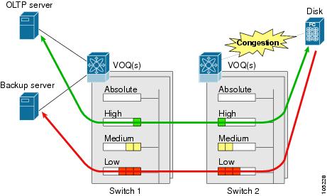
In this image, the OLTP traffic arriving at Switch 1 is marked with a high priority level of throughput classification (class map) and marking (policy map). Similarly, the backup traffic is marked with a low priority level. The traffic is sent to the corresponding priority queue within a virtual output queue (VOQ).
A deficit weighted round robin (DWRR) scheduler configured in the first switch ensures that high priority traffic is treated better than low priority traffic. For example, DWRR weights of 70:20:10 implies that the high priority queue is serviced at 7 times the rate of the low priority queue. This guarantees lower delays and higher bandwidths to high priority traffic if congestion sets in. A similar configuration in the second switch ensures the same traffic treatment in the other direction.
If the ISL is congested when the OLTP server sends a request, the request is queued in the high priority queue and is serviced almost immediately since the high priority queue is not congested. The scheduler assigns its priority over the backup traffic in the low priority queue.
 Note |
When the high priority queue does not have traffic flowing through, the low priority queue uses all the bandwidth and is not restricted to the configured value. |
A similar occurrence in Switch 2 sends a response to the transaction request. The round trip delay experienced by the OLTP server is independent of the volume of low priority traffic or the ISL congestion. The backup traffic uses the available ISL bandwidth when it is not used by the OLTP traffic.
Comparing VSAN Versus Zone-Based QoS
While you can configure both zone-based QoS and VSAN-based QoS configurations in the same switch, both configurations have significant differences. The following table highlights the differences between configuring QoS priorities based on VSANs versus zones.
|
VSAN-Based QoS |
Zone-Based QoS |
|---|---|
|
If you configure the active zone set on a given VSAN and also configure QoS parameters in any of the member zones, you cannot associate the policy map with the VSAN. |
You cannot activate a zone set on a VSAN that already has a policy map associated. |
|
If the same flow is present in two class maps associated to a policy map, the QoS value of the class map attached first takes effect. |
If the same flow is present in two zones in a given zone set with different QoS values, the higher QoS value is considered. |
|
— |
During a zone merge, if the Cisco NX-OS software detects a mismatch for the QoS parameter, the link is isolated. |
|
Takes effect only when QoS is enabled. |
Takes effect only when QoS is enabled. |
Configuring Data Traffic
To configure QoS using Fabric Manager, follow these steps:
Procedure
| Step 1 |
Enable the QoS feature. |
| Step 2 |
Create and define class maps. |
| Step 3 |
Define service policies. |
| Step 4 |
Apply the configuration. |
Information About Class Map Creation
Using the class map feature you can create and define traffic class with match criteria to identify traffic belonging to that class. The class map name is restricted to 63 alphanumeric characters and defaults to the match-all option. Flow-based traffic uses one of the following values:
- WWN—The source WWN or the destination WWN.
- Fibre Channel ID (FC ID) —The source ID (SID) or the destination ID (DID).
- Source interface—The ingress interface.
Use the class map feature to create and define a traffic class with match criteria to identify traffic belonging to that class. The class map name is restricted to 63 alphanumeric characters and defaults to the match-all option. Flow-based traffic uses one of the following values:
- WWN—The source WWN or the destination WWN.
- Fibre Channel ID (FC ID) —The source ID (SID) or the destination ID (DID). The possible values for mask are FFFFFF (the entire FC ID is used—this is the default), FFFF00 (only domain and area FC ID is used), or FF0000 (only domain FC ID is used).
Note |
An SID or DID of 0x000000 is not allowed. |
- Source interface—The ingress interface.
Tip |
The order of entries to be matched within a class map is not significant. |
Creating a Class Map
To create a class map, follow these steps:
Procedure
| Step 1 |
Expand Switches , expand FC Services and then select QoS in the Physical Attributes pane. The QoS information is displayed in the Information pane. The Control tab is the default. |
| Step 2 |
In the Class Maps tab, click Create Row to create a new class map. You see the Create Class Maps dialog box. |
| Step 3 |
Select the switches for the class map. |
| Step 4 |
Enter the source ID or the destination ID in the field. |
| Step 5 |
Enter a name for the class map. |
| Step 6 |
Select a Match mode. You can either match any or all criterion with one match statement from the class map configuration mode. |
| Step 7 |
Click Create to proceed with creating the class map. |
Information About Service Policy Definition
Service policies are specified using policy maps. Policy maps provide an ordered mapping of class maps to service levels. The order of the class maps within a policy map is important to determine the order in which the frame is compared to class maps. The first matching class map has the corresponding priority marked in the frame. You can specify multiple class maps within a policy map, and map a class map to a high, medium, or low service level. The default priority is low. Alternatively, you can map a class map to a differentiated services code point (DSCP). The DSCP is an indicator of the service level for a specified frame.
Service policies are specified using policy maps. Policy maps provide an ordered mapping of class maps to service levels. You can specify multiple class maps within a policy map, and map a class map to a high, medium, or low service level. The default priority is low. The policy map name is restricted to 63 alphanumeric characters.
As an alternative, you can map a class map to a differentiated services code point (DSCP).The DSCP is an indicator of the service level for a specified frame. The DSCP value ranges from 0 to 63, and the default is 0. A DSCP value of 46 is disallowed.
The order of the class maps within a policy map is important to determine the order in which the frame is compared to class maps. The first matching class map has the corresponding priority marked in the frame.
Note |
Refer to Implementing Quality of Service Policies with DSCP for further information on implementing QoS DSCP values. |
Note |
Class maps are processed in the order in which they are configured in each policy map. |
About Service Policy Enforcement
When you have configured a QoS data traffic policy, you must enforce the data traffic configuration by applying that policy to the required VSAN(s). If you do not apply the policy to a VSAN, the data traffic configuration is not enforced. You can only apply one policy map to a VSAN.
Note |
You can apply the same policy to a range of VSANs. |
About the DWRR Traffic Scheduler Queue
The DWRR scheduler services the queues in the ratio of the configured weights. Higher weights translate to proportionally higher bandwidth and lower latency. The default weights are 50 for the high queue, 30 for the medium queue, and 20 for the low queue. The Cisco NX-OS software supports four scheduling queues:
-
Strict priority queues are queues that are serviced in preference to other queues—it is always serviced if there is a frame queued in it regardless of the state of the other queues.
-
QoS assigns all other traffic to the DWRR scheduling high, medium, and low priority traffic queues.
The Cisco NX-OS software supports four scheduling queues:
-
Strict priority queues are queues that are serviced in preference to other queues—it is always serviced if there is a frame queued in it regardless of the state of the other queues.
-
QoS assigns all other traffic to the DWRR scheduling high, medium, and low priority traffic queues.
The DWRR scheduler services the queues in the ratio of the configured weights. Higher weights translate to proportionally higher bandwidth and lower latency. The default weights are 50 for the high queue, 30 for the medium queue, and 20 for the low queue. Decreasing order of queue weights is mandated to ensure the higher priority queues have a higher service level, though the ratio of the configured weights can vary (for example, one can configure 70:30:5 or 60:50:10 but not 50:70:10).
The following table describes the QoS behavior for Generation 1, Generation 2, and Generation 3 switching modules.
|
Source Module Type |
Destination Module Type |
QoS Behavior Description |
|---|---|---|
|
Generation 1 |
Generation 1 |
QoS behavior reflects the DWRR configuration for traffic coming in through a given port and queued to the same egress port. All the other traffic share equal bandwidth. |
|
Generation 1 |
Generation 2 or Generation 3 |
QoS behavior reflects the DWRR configuration for traffic coming in through a given port and queued to the same egress port. All the other streams share equal bandwidth. |
|
Generation 2 or Generation 3 |
Generation 1 |
Bandwidth partitioning is equal for all the traffic. |
|
Generation 2 or Generation 3 |
Generation 2 or Generation 3 |
QoS behavior reflects the DWRR weights configuration for all possible streams. |
Changing the Weight in a DWRR Queue
To change the weight in a DWRR queue using Fabric Manager, follow these steps:
Procedure
| Step 1 |
Expand Switches , expand FC Services and then select QoS in the Physical Attributes pane. The QoS control traffic information is displayed in the Information pane. The default is the Control tab. |
| Step 2 |
Click the DWRR tab. You see the queue status and weight. |
| Step 3 |
Select a switch and change the weight. |
| Step 4 |
Click the Apply Changes icon to save your changes. |
Limiting Ingress Port Rate Limiting
About Limiting Ingress Port Rate
A port rate limiting feature helps control the bandwidth for individual Fibre Channel ports. Port rate limiting is also referred to as ingress rate limiting because it controls ingress traffic into a Fibre Channel port. The feature controls traffic flow by limiting the number of frames that are transmitted out of the exit point on the MAC. Port rate limiting works on all Fibre Channel ports. The rate limit ranges from 1 to 100% and the default is 100%.
A port rate limiting feature helps control the bandwidth for individual Fibre Channel ports. Port rate limiting is also referred to as ingress rate limiting because it controls ingress traffic into a Fibre Channel port. The feature controls traffic flow by limiting the number of frames that are transmitted out of the exit point on the MAC. Port rate limiting works on all Fibre Channel ports. The rate limit ranges from 1 to 100% and the default is 100%.
Note |
Port rate limiting can only be configured on Cisco MDS 9100 Series switches, Cisco MDS 9216i switches, and MPS-14/2 modules. |
This feature can only be configured if the QoS feature is enabled and if this configuration is performed on a Cisco MDS 9100 series switch, Cisco MDS 9216i switch, or MPS-14/2 module.
To configure the port rate limiting value using Fabric Manager, follow these steps:
Procedure
| Step 1 |
Expand Switches , expand FC Services and then select QoS in the Physical Attributes pane. The QoS control traffic information is displayed in the Information pane. The default is the Control tab. |
| Step 2 |
Click the Rate Limit tab. |
| Step 3 |
Select the switch whose port rate limit you want to change. |
| Step 4 |
Enter the desired port rate limit in the Percent column. |
| Step 5 |
Click the Apply Changes icon to save your changes. |
 Feedback