Configuring IP Services
This chapter includes the following topics:
Information About IP Services
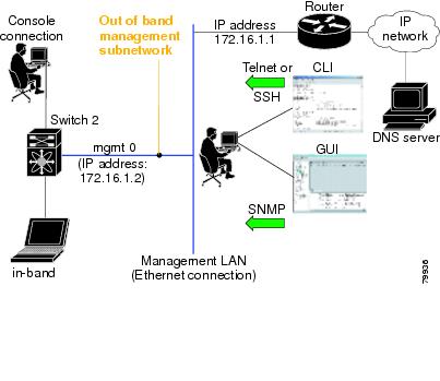
Cisco MDS 9000 Family switches can route IP traffic between Ethernet and Fibre Channel interfaces. The IP static routing feature is used to route traffic between VSANs. To do so, each VSAN must be in a different IP subnetwork. Each Cisco MDS 9000 Family switch provides the following services for network management systems (NMSs):
- IP forwarding on the out-of-band Ethernet interface (mgmt0) on the front panel of the supervisor modules.
- IP forwarding on in-band Fibre Channel interface using the IP over Fibre Channel (IPFC) function—IPFC specifies how IP frames can be transported over Fibre Channel using encapsulation techniques. IP frames are encapsulated into Fibre Channel frames so NMS information can cross the Fibre Channel network without using an overlay Ethernet network.
- IP routing (default routing and static routing)—If your configuration does not need an external router, you can configure a default route using static routing.
Switches are compliant with RFC 2338 standards for Virtual Router Redundancy Protocol (VRRP) features. VRRP is a restartable application that provides a redundant, alternate path to the gateway switch.
This section includes the following topics:
Traffic Management Services
In-band options are compliant with and use the RFC 2625 standards. An NMS host running the IP protocol over an Fibre Channel interface can access the switch using the IPFC functionality. If the NMS does not have a Fibre Channel HBA, in-band management can still be performed using one of the switches as an access point to the fabric as shown in Figure 1.
Management Interface Configuration
The management interface on the switch allows multiple simultaneous Telnet or SNMP sessions. You can remotely configure the switch through the management interface, but first you must configure IP version 4 (IPv4) parameters (IP address, subnet mask) or an IP version 6 (IPv6) address and prefix length so that the switch is reachable.
On director class switches, a single IP address is used to manage the switch. The active supervisor module's management (mgmt0) interface uses this IP address. The mgmt0 interface on the standby supervisor module remains in an inactive state and cannot be accessed until a switchover happens. After a switchover, the mgmt0 interface on the standby supervisor module becomes active and assumes the same IP address as the previously active supervisor module.
 Note |
The port on the Ethernet switch to which the MDS management interface is connected should be configured as a host port (also known as access port) instead of a switch port. Spanning tree configuration for that port (on the Ethernet switch) should disabled. This helps avoid the delay in the MDS management port coming up due to delay from Ethernet spanning tree processing that the Ethernet switch would run if enabled. |
Note |
Before you begin to configure the management interface manually, obtain the switch’s IP address and IP subnet mask. Also make sure the console cable is connected to the console port. |
About the Default Gateway
You can configure a default gateway IPv4 address on your Cisco MDS 9000 Family switch.
The default gateway IPv4 address should be configured along with the IPv4 static routing attributes (IP default network, destination prefix, and destination mask, and next hop address). If you configure the static route IP forwarding and the default-network details, these IPv4 addresses will be used regardless of the default-gateway being enabled or disabled.
The default gateway IPv4 address should be configured along with the IPv4 static routing attributes commands (IP default network, destination prefix, and destination mask, and next hop address).
 Tip |
If you configure the static route IP forwarding and the default-network details, these IPv4 addresses will be used regardless of the default-gateway being enabled or disabled. If these IP addresses are configured but not available, the switch will fall back to using the default gateway IP address, if you have configured it. Be sure to configure IP addresses for all entries in the switch. |
IPv4 Default Network Configuration
If you assign the IPv4 default network address, the switch considers routes to that network as the last resort. If the IPv4 default network address is not available, the switch uses the IPv4 default gateway address. For every network configured with the IPv4 default network address, the switch flags that route as a candidate default route, if the route is available.
Tip |
If you configure the static route IP forwarding and the default network details, these IPv4 addresses will be used regardless of the default gateway being enabled or disabled. If these IPv4 addresses are configured and not available, the switch will fall back to using the default gateway IPv4 address, if you have configured it. Be sure to configure IPv4 addresses for all entries in the switch if you are using IPv4. |
When the Ethernet interface is configured, the switch should point to the gateway router for the IP network. The host accesses the gateway using a gateway switch. This gateway switch is configured as the default gateway. The other switches in the fabric that are connected to the same VSAN as the gateway switch can also be connected through the gateway switch. Every interface connected to this VSAN should be configured with the VSAN IPv4 address of the gateway switch as shown in Figure 1
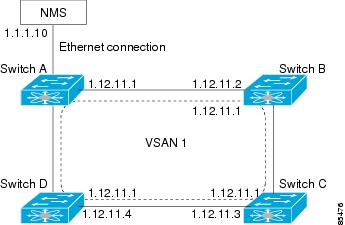
In the above figure, switch A has the IPv4 address 1.12.11.1, switch B has the IPv4 address 1.12.11.2, switch C has the IPv4 address 1.12.11.3, and switch D has the IPv4 address 1.12.11.4. Switch A is the gateway switch with the Ethernet connection. The NMS uses the IPv4 address 1.1.1.10 to connect to the gateway switch. Frames forwarded to any switch in the overlaid VSAN 1 are routed through the gateway switch. Configuring the gateway switch’s IPv4 address (1.12.11.1) in the other switches enable the gateway switch to forward the frame to the intended destination. Similarly, if a non-gateway switch in the VSAN forwards a frame to the Ethernet, the frame is routed through the gateway switch.
When forwarding is disabled (default), IP frames are not sent from one interface to another. In these cases, the software performs local IP routing between two switches using the in-band option for Fibre Channel traffic and the mgmt0 option for Ethernet traffic.
When a VSAN is created, a VSAN interface is not created automatically. You need to specifically create the interface.
IPFC
IPFC provides IP forwarding on in-band switch management over a Fibre Channel interface (rather than out-of-band using the Gigabit Ethernet mgmt 0 interface). You can be use IPFC to specify that IP frames can be transported over Fibre Channel using encapsulation techniques. IP frames are encapsulated into Fibre Channel frames so NMS information can cross the Fibre Channel network without using an overlay Ethernet network.
Once the VSAN interface is created, you can specify the IP address for that VSAN. You can assign an IPv4 address or an IPv6 address.
About IPv4 Static Routes
Static routing is a mechanism to configure IPv4 routes on the switch. You can configure more than one static route.
If a VSAN has multiple exit points, configure static routes to direct traffic to the appropriate gateway switch. IPv4 routing is disabled by default on any gateway switch between the out-of-band management interface and the default VSAN, or between directly connected VSANs.
If your network configuration does not need an external router, you can configure IPv4 static routing on your MDS switch.
About Overlay VSANs
VSANs enable deployment of larger SANs by overlaying multiple logical SANs, each running its own instance of fabric services, on a single large physical network. This partitioning of fabric services reduces network instability by containing fabric reconfiguration and error conditions within an individual VSAN. VSANs also provide the same isolation between individual VSANs as physically separated SANs. Traffic cannot cross VSAN boundaries and devices may not reside in more than one VSAN. Because each VSAN runs separate instances of fabric services, each VSAN has its own zone server and can be zoned in exactly the same way as SANs without VSAN capability.
About VRRP
Cisco MDS 9000 Family switches are compliant with RFC 2338 standards for Virtual Router Redundancy Protocol (VRRP) features. VRRP provides a redundant alternative path to the gateway switch, which has connectivity to the NMS. VRRP has the following features:
- VRRP is a restartable application.
- When a VRRP master fails, the VRRP backup takes over within three times the advertisement time.
- VRRP over Ethernet, VRRP over VSAN, and Fibre Channel functions are implemented as defined in RFC 2338 and the draft-ietf-vrrp-ipv6 specification.
- A virtual router is mapped to each VSAN and Ethernet interface with its unique virtual router IP, virtual router MAC, and VR ID.
- VR IDs can be reused in multiple VSANs with different virtual router IP mapping.
- Both IPv4 and IPv6 is supported.
- The management interface (mgmt 0) supports only one virtual router group. All other interfaces each support up to seven virtual router groups, including both IPv4 and IPv6 combined. Up to 255 virtual router groups can be assigned in each VSAN.
- VRRP security provides three options, including no authentication, simple text authentication, and MD5 authentication.
Note |
If you are using IPv6, you must either configure an IPv6 address on the interface or enable IPv6 on the interface. |
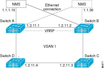
In Figure 1, switch A is the VRRP master and switch B is the VRRP backup switch. Both switches have an IP address to VRRP mapping configured. The other switches set switch A as the default gateway. If switch A fails, the other switches do not have to change the routing configurations as switch B automatically becomes the master and takes over the function of a gateway.
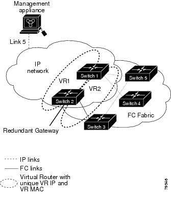
In Figure 2, the fabric example has two virtual router groups (VR1 and VR 2) because a virtual router cannot span across different types of interfaces. In both switch 1 and switch 2, the Ethernet interface is in VR 1 and the FC interface is in VR 2. Each virtual router is uniquely identified by the VSAN interface and the VR ID.
DNS Server Configuration
The DNS client on the switch communicates with the DNS server to perform the IP address-name server correspondence.
The DNS server may be dropped after two attempts because of one of the following reasons:
- The IP address or the switch name is wrongly configured.
- The DNS server is not reachable because external reasons (reasons beyond our control).
Note |
When accessing a Telnet host, if the DNS server is not reachable (for any reason) the switch login prompt may take a longer time to appear. If so, verify that the DNS server is accurately configured and reachable. |
Guidelines and Limitations
Follow these guidelines to configure IPFC:
- Create the VSAN to use for in-band management, if necessary.
- Configure an IPv4 address and subnet mask for the VSAN interface.
- Enable IPv4 routing.
- Verify connectivity.
Default Settings
Table 1 lists the default settings for DNS features.
|
Parameters |
Default |
|---|---|
|
Domain lookup |
Disabled |
|
Domain name |
Disabled |
|
Domains |
None |
|
Domain server |
None |
|
Maximum domain servers |
6 |
Table 2 lists the default settings for VRRP features.
|
Parameters |
Default |
|---|---|
|
Virtual router state |
Disabled |
|
Maximum groups per VSAN |
255 |
|
Maximum groups per Gigabit Ethernet port |
7 |
|
Priority preemption |
Disabled |
|
Virtual router priority |
100 for switch with secondary IP addresses 255 for switches with the primary IP address |
|
Priority interface state tracking |
Disabled |
|
Advertisement interval |
1 second for IPv4 100 centiseconds for IPv6 |
Configuring IP Services
This section includes the following topics:
Configuring Management Interface
To configure the mgmt0 Ethernet interface using Device Manager for IPv6, follow these steps:
Procedure
| Step 1 |
Select Interface > Mgmt > Mgmt0 . |
| Step 2 |
Enter the description. |
| Step 3 |
Select the administrative state of the interface. |
| Step 4 |
Check the CDP check box to enable CDP. |
| Step 5 |
Enter the IP address mask. |
| Step 6 |
Click Apply to apply the changes. |
Configuring the Default Gateway
To configure an IP route, follow these steps:
Procedure
| Step 1 |
Select Switches > Interfaces > Management, and select IP in the Physical Attributes pane. |
||
| Step 2 |
Click the Route tab in the information pane. You see the IP route window showing the switch name, destination, mask, gateway, metric, interface, and active status of each IP route. |
||
| Step 3 |
Click the Create Row icon to add a new IP route. |
||
| Step 4 |
Complete the fields in this window.
|
||
| Step 5 |
Click the Create icon. |
Configuring an IP route or identify the default gateway using Device Manager
To configure an IP route or identify the default gateway using Device Manager, follow these steps:
Procedure
| Step 1 |
Choose IP > Routes. You see the IP Routes window. |
||
| Step 2 |
Create a new IP route or identify the default gateway on a switch by clicking Create. |
||
| Step 3 |
Complete the fields in this window.
If you choose the CPP interface, the switch uses the input CPP-assigned IP address and mask to generate the IP route prefix. |
||
| Step 4 |
Click Create to add the IP route.
|
Configuring Overlay VSANs
To configure an overlay VSAN, follow these steps:
Procedure
| Step 1 |
Add the VSAN to the VSAN database on all switches in the fabric. |
| Step 2 |
Create a VSAN interface for the VSAN on all switches in the fabric. Any VSAN interface belonging to the VSAN has an IP address in the same subnet. Create a route to the IPFC cloud on the IP side. |
| Step 3 |
Configure a default route on every switch in the Fibre Channel fabric pointing to the switch that provides NMS access. |
| Step 4 |
Configure the default gateway (route) and the IPv4 address on switches that point to the NMS as shown in Figure 1. 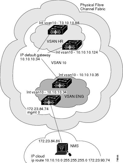
|
What to do next
Note |
To configure the management interface displayed in Figure 1, set the default gateway to an IPv4 address on the Ethernet network. |
The following procedure configures an overlay VSAN in one switch. This procedure must be repeated for each switch in the fabric.
Configuring Multiple VSANs
More than one VSAN can be used to segment the management network in multiple subnets. An active interface must be present on the switch for the VSAN interface to be enabled.
To configure multiple VSANs, follow these steps:
Procedure
| Step 1 |
Add the VSAN to the VSAN database on any switch in the fabric. |
| Step 2 |
Create a VSAN interface for the appropriate VSAN on any switch in the fabric. |
| Step 3 |
Assign an IP address on every VSAN interface on the same subnet as the corresponding VSAN. |
| Step 4 |
Define the multiple static routes on the Fibre Channel switches and the IP cloud as shown in Figure 41-6 . 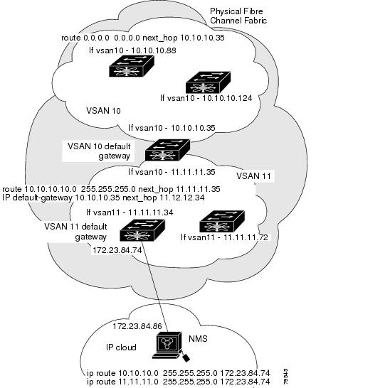
|
Configuring VRRP
This section describes how to configure VRRP and includes the following topics:
Adding and Deleting a Virtual Router
All VRRP configurations should be replicated across switches in a fabric that runs VRRP.
Note |
The total number of VRRP groups that you can configure on a Gigabit Ethernet port, including main interfaces and subinterfaces, cannot exceed seven. This limitation applies to both IPv4 and IPv6 groups. |
Virtual Router Initiation
By default, a virtual router is always disabled. VRRP can be configured only if this state is enabled. Be sure to configure at least one IP address, either IPv4 or IPv6, before attempting to enable a VR.
Adding Virtual Router IP Addresses
One virtual router IP address can be configured for a virtual router. If the configured IP address is the same as the interface IP address, this switch automatically owns the IP address. You can configure either an IPv4 address or an IPv6 address.
According to the VRRP specification, the master VRRP router drops the packets addressed to the virtual router's IP address because the virtual router is only intended as a next-hop router to forward packets. In MDS switches however, some applications require that packets addressed to virtual router's IP address be accepted and delivered to them. By using the secondary option to the virtual router IPv4 address, the VRRP router will accept these packets when it is the master.
To manage IP addresses for virtual routers from Device Manager, follow these steps:
Procedure
| Step 1 |
Choose IP > VRRP. You see the Operations tab of the VRRP dialog box. |
| Step 2 |
Click the IP Addresses tab on the VRRP dialog box. |
| Step 3 |
To create a new VRRP entry, click Create. You see the Create VRRP IP Addresses window. |
| Step 4 |
Complete the fields in this window to create a new VRRP IP address, and click OK or Apply. |
Setting the Priority for the Virtual Router
The valid range to assign a virtual router priority is 1 to 254 with 1 being the lowest priority and 254 being the highest priority. The default value is 100 for switches with secondary IP addresses and 255 for switches with the primary IP address.
Setting the Time Interval for Advertisement Packets
The valid time range for an advertisement packet on an interface using IPv4 is between 1 and 255 seconds. The default value is 1 (one) second. If the switch has the primary IP address, this time must be specified.
Configuring or Enabling Priority Preemption
You can enable a higher-priority backup virtual router to preempt the lower-priority master virtual router.
Note |
If the virtual IP address is also the IP address for the interface, then preemption is implicitly applied. |
Note |
The VRRP preemption is not supported on IP storage Gigabit Ethernet interfaces. |
Setting Virtual Router Authentication
VRRP security provides three options, including simple text authentication, MD5 authentication, and no authentication.
- Simple text authentication uses a unique, 1 to 8 character password that is used by all switches participating in the same virtual router. This password should be different from other security passwords.
- MD5 authentication uses a unique, 16 character key that is shared by all switches participating in the same virtual router. This secret key is shared by all switches in the same virtual router.
- No authentication is the default option.
You can configure the key using the authentication option in the VRRP submode and distribute it using the configuration file. The security parameter index (SPI) settings assigned in this option should be unique for each VSAN.
Note |
All VRRP configurations must be duplicated. |
Note |
VRRP router authentication does not apply to IPv6. |
Tracking the Interface Priority
Interface state tracking changes the priority of the virtual router based on the state of another interface in the switch. When the tracked interface is down, the priority reverts to the priority value for the virtual router (see the Setting the Priority for the Virtual Router). When the tracked interface is up, the priority of the virtual router is restored to the interface state tracking value. You can track the state of either a specified VSAN interface or the management interface (mgmt 0). The interface state tracking feature is disabled by default.
Note |
For interface state tracking to function, you must enable preemption on the interface. |
Field Descriptions for IP Services
This section describes the field descriptions.
IP Routes
|
Field |
Description |
|---|---|
|
Routing Enabled |
When this check box is enabled, the switch is acting as in IP router. |
|
Destination, Mask, Gateway |
The value that identifies the local interface through which the next hop of this route should be reached. |
|
Metric |
The primary routing metric for this route. |
|
Interface |
The local interface through which the next hop of this route should be reached. |
|
Active |
Indicates whether the route is active. |
IP Statistics ICMP
|
Field |
Description |
|---|---|
|
InParmProbs |
The number of ICMP Parameter Problem messages received. |
|
OutParmProbs |
The number of ICMP Parameter Problem messages sent. |
|
InSrcQuenchs |
The number of ICMP Source Quench messages received. |
|
InRedirects |
The number of ICMP Redirect messages received. |
|
InEchos |
The number of ICMP Echo (request) messages received. |
|
InEchoReps |
The number of ICMP Echo Reply messages received. |
|
InTimestamps |
The number of ICMP Timestamp (request) messages received. |
|
InTimestampReps |
The number of ICMP Timestamp Reply messages received. |
|
InAddrMasks |
The number of ICMP Address Mask Request messages received. |
|
InAddrMaskReps |
The number of ICMP Address Mask Reply messages received. |
|
InDestUnreachs |
The number of ICMP Destination Unreachable messages received. |
|
InTimeExcds |
The number of ICMP Time Exceeded messages received. |
|
OutSrcQuenchs |
The number of ICMP Source Quench messages sent. |
|
OutRedirects |
The number of ICMP Redirect messages sent. For a host, this value will always be N/A, since hosts do not send redirects. |
|
OutEchos |
The number of ICMP Echo (request) messages sent. |
|
OutEchoReps |
The number of ICMP Echo Reply messages sent. |
|
OutTimestamps |
The number of ICMP Timestamp (request) messages sent. |
|
OutTimestampReps |
The number of ICMP Timestamp Reply messages sent. |
|
OutAddrMasks |
The number of ICMP Address Mask Request messages sent. |
|
OutAddrMaskReps |
The number of ICMP Address Mask Reply messages sent. |
|
OutDestUnreachs |
The number of ICMP Destination Unreachable messages sent. |
|
OutTimeExcds |
The number of ICMP Time Exceeded messages sent. |
IP Statistics IP
|
Field |
Description |
|---|---|
|
InHdrErrors |
The number of input datagrams discarded due to errors in their IP headers, including bad checksums, version number mismatch, other format errors, time-to-live exceeded, errors discovered in processing their IP options, etc. |
|
InAddrErrors |
The number of input datagrams discarded because the IP address in their IP header's destination field was not a valid address to be received at this entity. For entities that are not IP routers, and do not forward datagrams, this counter includes datagrams discarded because the destination address was not a local address. |
|
InUnknownProtos |
The number of locally-addressed datagrams received successfully but discarded because of an unknown or unsupported protocol. |
|
InDiscards |
The number of input IP datagrams for which no problems were encountered to prevent their continued processing, but which were discarded (for example, for lack of buffer space). Note that this counter does not include any datagrams discarded while awaiting re-assembly. |
|
OutDiscards |
The number of output IP datagrams for which no problem was encountered to prevent their transmission to their destination, but which were discarded (for example, for lack of buffer space). Note that this counter would include datagrams counted in ipForwDatagrams if any such frames met this (discretionary) discard criterion. |
|
OutNoRoutes |
The number of IP datagrams discarded because no route could be found to transmit them to their destination. Note that this counter includes any frames counted in ipForwDatagrams which meet this no-route criterion. Note that this includes any datagrams which a host cannot route because all of its default routers are down. |
|
FragFails |
The number of IP datagrams that have been discarded because they needed to be fragmented at this entity but could not be, for example, because their Don't Fragment flag was set. |
|
ReasmFails |
The number of failures detected by the IP reassembly algorithm (for example, timed out, errors, etc). Note that this is not necessarily a count of discarded IP fragments since some algorithms (notably the algorithm in RFC 815) can lose track of the number of fragments by combining them as they are received. |
|
InReceives |
The total number of input datagrams received from interfaces, including those received in error. |
|
InDelivers |
The total number of input datagrams successfully delivered to IP user protocols (including ICMP). |
|
OutRequests |
The total number of IP datagrams which local IP user protocols (including ICMP) supplied to IP in requests for transmission. Note that this counter does not include any datagrams counted in ipForwDatagrams. |
|
ForwDatagrams |
The number of input datagrams for which this entity was not their final IP destination, as a result of which an attempt was made to find a route to forward them to that final destination. In entities which do not act as IP routers, this counter will include only those frames which were source-routed via this entity, and the Source-Route option processing was successful. |
|
FragOKs |
The number of IP datagrams that have been successfully fragmented at this entity. |
|
FragCreates |
The number of IP datagram fragments that have been generated as a result of fragmentation at this entity. |
|
ReasmReqds |
The number of IP fragments received which needed to be reassembled at this entity. |
|
ReasmOKs |
The number of IP datagrams successfully reassembled. |
IP Statistics SNMP
|
Field |
Description |
|---|---|
|
BadVersions |
The total number of SNMP messages which were delivered to the SNMP entity and were for an unsupported SNMP version. |
|
BadCommunityNames |
The total number of SNMP messages delivered to the SNMP entity which used a SNMP community name not known to said entity. |
|
BadCommunityUses |
The total number of SNMP messages delivered to the SNMP entity which represented an SNMP operation which was not allowed by the SNMP community named in the message. |
|
ASNParseErrs |
The total number of ASN.1 or BER errors encountered by the SNMP entity when decoding received SNMP messages. |
|
TooBigs |
The total number of SNMP PDUs which were delivered to the SNMP protocol entity and for which the value of the error-status field is tooBig. |
|
SilentDrops |
The total number of GetRequest-PDUs, GetNextRequest-PDUs, GetBulkRequest-PDUs, SetRequest-PDUs, and InformRequest-PDUs delivered to the SNMP entity which were silently dropped because the size of a reply containing an alternate Response-PDU with an empty variable-bindings field was greater than either a local constraint or the maximum message size associated with the originator of the request. |
|
ProxyDrops |
The total number of GetRequest-PDUs, GetNextRequest-PDUs, GetBulkRequest-PDUs, SetRequest-PDUs, and InformRequest-PDUs delivered to the SNMP entity which were silently dropped because the transmission of the (possibly translated) message to a proxy target failed in a manner (other than a timeout) such that no Response-PDU could be returned. |
|
NoSuchNames |
The total number of SNMP PDUs which were delivered to the SNMP protocol entity and for which the value of the error-status field is noSuchName. |
|
BadValues |
The total number of SNMP PDUs which were delivered to the SNMP protocol entity and for which the value of the error-status field is badValue. |
|
ReadOnlys |
The total number valid SNMP PDUs which were delivered to the SNMP protocol entity and for which the value of the error-status field is readOnly. It should be noted that it is a protocol error to generate an SNMP PDU which contains the value readOnly in the error-status field, as such this is provided as a means of detecting incorrect implementations of the SNMP. |
|
GenErrs |
The total number of SNMP PDUs which were delivered to the SNMP protocol entity and for which the value of the error-status field is genErr. |
|
Pkts |
The total number of messages delivered to the SNMP entity from the transport service. |
|
GetRequests |
The total number of SNMP Get-Request PDUs which have been accepted and processed by the SNMP protocol entity. |
|
GetNexts |
The total number of SNMP Get-Next PDUs which have been accepted and processed by the SNMP protocol entity. |
|
SetRequests |
The total number of SNMP Set-Request PDUs which have been accepted and processed by the SNMP protocol entity. |
|
OutTraps |
The total number of SNMP Trap PDUs which have been generated by the SNMP protocol entity. |
|
OutGetResponses |
The total number of SNMP Get-Response PDUs which have been generated by the SNMP protocol entity. |
|
OutPkts |
The total number of SNMP Messages which were passed from the SNMP protocol entity to the transport service. |
|
TotalReqVars |
The total number of MIB objects which have been retrieved successfully by the SNMP protocol entity as the result of receiving valid SNMP Get-Request and Get-Next PDUs. |
|
TotalSetVars |
The total number of MIB objects which have been altered successfully by the SNMP protocol entity as the result of receiving valid SNMP Set-Request PDUs. |
IP Statistics UDP
|
Field |
Description |
|---|---|
|
InErrors |
The number of received UDP datagrams that could not be delivered for reasons other than the lack of an application at the destination port. |
|
InDatagrams |
The total number of UDP datagrams delivered to UDP users. |
|
OutDatagrams |
The total number of UDP datagrams sent from this entity. |
|
NoPorts |
The total number of received UDP datagrams for which there was no application at the destination port. |
mgmt0 Statistics
|
Field |
Description |
|---|---|
|
InErrors |
Total number of received errors on the interface. |
|
OutErrors |
Total number of transmitted errors on the interface. |
|
InDiscards |
Total number of received discards on the interface. |
|
OutDiscards |
Total number of transmitted discards on the interface. |
|
RxBytes |
Total number of bytes received. |
|
TxBytes |
Total number of bytes transmitted. |
|
RxFrames |
Total number of frames received. |
|
TxFrames |
Total number of frames transmitted. |
TCP UDP TCP
|
Field |
Description |
|---|---|
|
State |
The state of this TCP connection. |
TCP UDP UDP
|
Field |
Description |
|---|---|
|
Port |
The local port number for this UDP listener. |
VRRP General
|
Field |
Description |
|---|---|
|
IP Address Type, VrId, Interface |
The IP address type (IPv4, IPv6, or DNS), the virtual router ID, and the interface. |
|
Admin |
The admin state of the virtual router (active or notInService). |
|
Oper |
The current state of the virtual router. There are three defined values:
|
|
Priority |
Specifies the priority to be used for the virtual router master election process. Higher values imply higher priority. A priority of 0 is sent by the master router to indicate that this router has ceased to participate in VRRP and a backup virtual router should transition to become a new master. A priority of 255 is used for the router that owns the associated IP address(es). |
|
AdvInterval |
The time interval, in seconds, between sending advertisement messages. Only the master router sends VRRP advertisements. |
|
PreemptMode |
Controls whether a higher priority virtual router will preempt a lower priority master. |
|
UpTime |
When this virtual router transitioned out of initialized. |
|
Version |
The VRRP version on which this VRRP instance is running. |
|
AcceptMode |
Controls whether a virtual router in Master state will accept packets addressed to the address owner's IPv6 address as its own if it is not the IPv6 address owner. If true, the virtual router in Master state will accept. If false, the virtual router in Master state will not accept. |
VRRP IP Addresses
|
Field |
Description |
|---|---|
|
Interface, VRRP ID, IP Address |
Interface, Virtual Router Redundancy Protocol ID, and associated IP address. |
VRRP Statistics
|
Field |
Description |
|---|---|
|
IP Address Type, VrId, Interface |
The IP address type (IPv4, IPv6, or DNS), the virtual router ID, and the interface. |
|
LastAdvRx |
The total number of VRRP advertisements received by this virtual router. |
|
Protocol Traffic MasterIpAddr |
The master router's real (primary) IP address. This is the IP address listed as the source in VRRP advertisement last received by this virtual router. |
|
Protocol Traffic BecomeMaster |
The total number of times that this virtual router's state has transitioned to MASTER. |
|
Priority 0 Rx |
The total number of VRRP frames received by the virtual router with a priority of 0. |
|
Priority 0Tx |
The total number of VRRP frames sent by the virtual router with a priority of 0. |
|
AuthErrors InvalidType |
The total number of frames received with an unknown authentication type. |
|
Other Errors dvIntervalErrors |
The total number of VRRP advertisement frames received for which the advertisement interval is different than the one configured for the local virtual router. |
|
Other Errors IpTtlErrors |
The total number of VRRP frames received by the virtual router with IP TTL (time-to-live) not equal to 255. |
|
Other Errors InvalidTypePktsRcvd |
The number of VRRP frames received by the virtual router with an invalid value in the type field. |
|
Other Errors AddressListErrors |
The total number of frames received for which the address list does not match the locally configured list for the virtual router. |
|
OtherErrors PacketLengthErrs |
The total number of frames received with a frame length less than the length of the VRRP header. |
|
RefreshRate |
The interval of time between refreshes. |
CDP General
|
Field |
Description |
|---|---|
|
Enable |
Whether the Cisco Discovery Protocol is currently running. Entries in CacheTable are deleted when CDP is disabled. |
|
MessageInterval |
The interval at which CDP messages are to be generated. The default value is 60 seconds. |
|
HoldTime |
The time for the receiving device holds CDP message. The default value is 180 seconds. |
|
LastChange |
When the cache table was last changed. |
CDP Neighbors
|
Field |
Description |
|---|---|
|
Switch |
The Internet address for this entity. |
|
Local Interface |
A unique value that identifies the interface on this FCIP device to which this link pertains. |
|
DeviceName |
The remote device's name. By convention, it is the device's fully qualified domain name. |
|
DeviceID |
The device ID string as reported in the most recent CDP message. |
|
DevicePlatform |
The version string as reported in the most recent CDP message. |
|
Interface |
The port ID string as reported in the most recent CDP message. |
|
IPAddress |
The (first) network-layer address of the device's SNMP-agent as reported in the address TLV of the most recently received CDP message. |
|
NativeVLAN |
The remote device's interface's native VLAN, as reported in the most recent CDP message. The value 0 indicates no native VLAN field (TLV) was reported in the most recent CDP message. |
|
PrimaryMgmtAddr |
Indicates the (first) network layer address at which the device will accept SNMP messages as reported in the most recently received CDP message. |
|
SecondaryMgmtAddr |
Indicates the alternate network layer address at which the device will accept SNMP messages as reported in the most recently received CDP message. |
iSNS Profiles
|
Field |
Description |
|---|---|
|
Addr |
The address of the iSNS server. |
|
Port |
The TCP port of the iSNS server. |
iSNS Servers
|
Field |
Description |
|---|---|
|
Name |
The name of the iSNS server. |
|
TcpPort |
The TCP port used for iSNS messages. If TCP is not supported by this server, the value is 0. |
|
Uptime |
The time the server has been active. |
|
ESI Non Response Threshold |
The number of ESI messages that will be sent without receiving a response before an entity is unregistered from the iSNS database. |
|
# Entities |
The number of entities registered in iSNS on the server. |
|
# Portals |
The number of portals registered in iSNS on the server. |
|
# Portal Groups |
The number of portal groups registered in iSNS on the server. |
|
# iSCSI Devices |
The number of iSCSI Nodes registered in iSNS on the server. |
iSNS Entities
|
Field |
Description |
|---|---|
|
Entity ID |
The iSNS entity identifier for the entity. |
|
Last Accessed |
The time the entity was last accessed. |
iSNS Cloud Discovery
|
Field |
Description |
|---|---|
|
AutoDiscovery |
Whether automatic cloud discovery is turned on or off. |
|
DiscoveryDelay |
Time duration between successive IP cloud discovery runs. |
|
Discovery |
The IP network discovery command to be executed.
|
|
CommandStatus |
The status of the license install / uninstall / update operation.
|
iSNS Clouds
|
Field |
Description |
|---|---|
|
Id |
The ID of the IP cloud. |
|
Switch WWN |
The WWN of the switch in this table. |
iSNS Cloud Interfaces
|
Field |
Description |
|---|---|
|
Name, Switch WWN, Interface, Address |
The name, switch WWN, interface, and address of the cloud. |
Monitor Dialog Controls
|
Field |
Description |
|---|---|
|
Line Chart |
Opens a new window with a line chart representation of the data. |
|
Area Chart |
Opens a new window with an area chart representation of the data. |
|
Bar Chart |
Opens a new window with a bar chart representation of the data. |
|
Pie Chart |
Opens a new window with a pie chart representation of the data. |
|
Reset Cumulative Counters |
Resets the counters to 0 if the Column Data display mode is set to Cumulative. |
|
Export to File |
Opens a standard Save dialog box. The data is saved as a .TXT file. |
|
|
Opens a standard Print dialog box. |
|
Update Frequency |
The interval at which the data is updated in the monitor dialog. |
|
Column Data |
Specifies the type of data that is displayed in the monitor dialog.
|
|
Elapsed |
The amount of time that has elapsed since the dialog was opened. You can reset this counter by clicking the Reset Cumulative Counters button, to gather a new set of cumulative data. |
iSNS Details iSCSI Nodes
|
Field |
Description |
|---|---|
|
Name |
The iSCSI name of the initiator or target associated with the storage node. |
|
Type |
The Node Type bit-map defining the functions of this iSCSI node, where 31 is a Target, 30 is an Initiator, 29 is a Control, and all others are reserved. |
|
Alias |
The Alias name of the iSCSI node. |
|
ScnBitmap |
The State Change Notification (SCN) bitmap for a node. |
|
WWN Token |
An optional globally unique 64-bit integer value that can be used to represent the world wide node name of the iSCSI device in a Fibre Channel fabric. |
|
AuthMethod |
The iSCSI authentication method enabled for this iSCSI node. |
iSNS Details Portals
|
Field |
Description |
|---|---|
|
Addr |
The Internet address for this portal. |
|
TcpPort |
The port number for this portal. |
|
SymName |
The optional Symbolic Name for this portal. |
|
EsiInterval |
The Entity Status Inquiry (ESI) Interval for this portal. |
|
TCP ESI |
The TCP port number used for ESI monitoring. |
|
TCP Scn |
The TCP port used to receive SCN messages from the iSNS server. |
|
SecurityInfo |
Security attribute settings for the portal as registered in the Portal Security Bitmap attribute. |
 Feedback